EP2952440A1 - Receiving body, holding device and composite receiving body - Google Patents
Receiving body, holding device and composite receiving body Download PDFInfo
- Publication number
- EP2952440A1 EP2952440A1 EP15166236.8A EP15166236A EP2952440A1 EP 2952440 A1 EP2952440 A1 EP 2952440A1 EP 15166236 A EP15166236 A EP 15166236A EP 2952440 A1 EP2952440 A1 EP 2952440A1
- Authority
- EP
- European Patent Office
- Prior art keywords
- receiving
- receiving body
- bodies
- space
- webs
- Prior art date
- Legal status (The legal status is an assumption and is not a legal conclusion. Google has not performed a legal analysis and makes no representation as to the accuracy of the status listed.)
- Granted
Links
Images


Classifications
-
- B—PERFORMING OPERATIONS; TRANSPORTING
- B65—CONVEYING; PACKING; STORING; HANDLING THIN OR FILAMENTARY MATERIAL
- B65D—CONTAINERS FOR STORAGE OR TRANSPORT OF ARTICLES OR MATERIALS, e.g. BAGS, BARRELS, BOTTLES, BOXES, CANS, CARTONS, CRATES, DRUMS, JARS, TANKS, HOPPERS, FORWARDING CONTAINERS; ACCESSORIES, CLOSURES, OR FITTINGS THEREFOR; PACKAGING ELEMENTS; PACKAGES
- B65D19/00—Pallets or like platforms, with or without side walls, for supporting loads to be lifted or lowered
- B65D19/0002—Platforms, i.e. load supporting devices without provision for handling by a forklift
-
- B—PERFORMING OPERATIONS; TRANSPORTING
- B65—CONVEYING; PACKING; STORING; HANDLING THIN OR FILAMENTARY MATERIAL
- B65D—CONTAINERS FOR STORAGE OR TRANSPORT OF ARTICLES OR MATERIALS, e.g. BAGS, BARRELS, BOTTLES, BOXES, CANS, CARTONS, CRATES, DRUMS, JARS, TANKS, HOPPERS, FORWARDING CONTAINERS; ACCESSORIES, CLOSURES, OR FITTINGS THEREFOR; PACKAGING ELEMENTS; PACKAGES
- B65D19/00—Pallets or like platforms, with or without side walls, for supporting loads to be lifted or lowered
- B65D19/38—Details or accessories
- B65D19/385—Frames, corner posts or pallet converters, e.g. for facilitating stacking of charged pallets
-
- B—PERFORMING OPERATIONS; TRANSPORTING
- B65—CONVEYING; PACKING; STORING; HANDLING THIN OR FILAMENTARY MATERIAL
- B65D—CONTAINERS FOR STORAGE OR TRANSPORT OF ARTICLES OR MATERIALS, e.g. BAGS, BARRELS, BOTTLES, BOXES, CANS, CARTONS, CRATES, DRUMS, JARS, TANKS, HOPPERS, FORWARDING CONTAINERS; ACCESSORIES, CLOSURES, OR FITTINGS THEREFOR; PACKAGING ELEMENTS; PACKAGES
- B65D19/00—Pallets or like platforms, with or without side walls, for supporting loads to be lifted or lowered
- B65D19/38—Details or accessories
- B65D19/44—Elements or devices for locating articles on platforms
-
- B—PERFORMING OPERATIONS; TRANSPORTING
- B65—CONVEYING; PACKING; STORING; HANDLING THIN OR FILAMENTARY MATERIAL
- B65D—CONTAINERS FOR STORAGE OR TRANSPORT OF ARTICLES OR MATERIALS, e.g. BAGS, BARRELS, BOTTLES, BOXES, CANS, CARTONS, CRATES, DRUMS, JARS, TANKS, HOPPERS, FORWARDING CONTAINERS; ACCESSORIES, CLOSURES, OR FITTINGS THEREFOR; PACKAGING ELEMENTS; PACKAGES
- B65D2519/00—Pallets or like platforms, with or without side walls, for supporting loads to be lifted or lowered
- B65D2519/00004—Details relating to pallets
- B65D2519/00009—Materials
- B65D2519/00014—Materials for the load supporting surface
- B65D2519/00024—Metal
-
- B—PERFORMING OPERATIONS; TRANSPORTING
- B65—CONVEYING; PACKING; STORING; HANDLING THIN OR FILAMENTARY MATERIAL
- B65D—CONTAINERS FOR STORAGE OR TRANSPORT OF ARTICLES OR MATERIALS, e.g. BAGS, BARRELS, BOTTLES, BOXES, CANS, CARTONS, CRATES, DRUMS, JARS, TANKS, HOPPERS, FORWARDING CONTAINERS; ACCESSORIES, CLOSURES, OR FITTINGS THEREFOR; PACKAGING ELEMENTS; PACKAGES
- B65D2519/00—Pallets or like platforms, with or without side walls, for supporting loads to be lifted or lowered
- B65D2519/00004—Details relating to pallets
- B65D2519/00009—Materials
- B65D2519/00049—Materials for the base surface
- B65D2519/00059—Metal
-
- B—PERFORMING OPERATIONS; TRANSPORTING
- B65—CONVEYING; PACKING; STORING; HANDLING THIN OR FILAMENTARY MATERIAL
- B65D—CONTAINERS FOR STORAGE OR TRANSPORT OF ARTICLES OR MATERIALS, e.g. BAGS, BARRELS, BOTTLES, BOXES, CANS, CARTONS, CRATES, DRUMS, JARS, TANKS, HOPPERS, FORWARDING CONTAINERS; ACCESSORIES, CLOSURES, OR FITTINGS THEREFOR; PACKAGING ELEMENTS; PACKAGES
- B65D2519/00—Pallets or like platforms, with or without side walls, for supporting loads to be lifted or lowered
- B65D2519/00004—Details relating to pallets
- B65D2519/00009—Materials
- B65D2519/00223—Materials for the corner elements or corner frames
- B65D2519/00233—Metal
-
- B—PERFORMING OPERATIONS; TRANSPORTING
- B65—CONVEYING; PACKING; STORING; HANDLING THIN OR FILAMENTARY MATERIAL
- B65D—CONTAINERS FOR STORAGE OR TRANSPORT OF ARTICLES OR MATERIALS, e.g. BAGS, BARRELS, BOTTLES, BOXES, CANS, CARTONS, CRATES, DRUMS, JARS, TANKS, HOPPERS, FORWARDING CONTAINERS; ACCESSORIES, CLOSURES, OR FITTINGS THEREFOR; PACKAGING ELEMENTS; PACKAGES
- B65D2519/00—Pallets or like platforms, with or without side walls, for supporting loads to be lifted or lowered
- B65D2519/00004—Details relating to pallets
- B65D2519/00258—Overall construction
- B65D2519/00283—Overall construction of the load supporting surface
- B65D2519/00288—Overall construction of the load supporting surface made of one piece
-
- B—PERFORMING OPERATIONS; TRANSPORTING
- B65—CONVEYING; PACKING; STORING; HANDLING THIN OR FILAMENTARY MATERIAL
- B65D—CONTAINERS FOR STORAGE OR TRANSPORT OF ARTICLES OR MATERIALS, e.g. BAGS, BARRELS, BOTTLES, BOXES, CANS, CARTONS, CRATES, DRUMS, JARS, TANKS, HOPPERS, FORWARDING CONTAINERS; ACCESSORIES, CLOSURES, OR FITTINGS THEREFOR; PACKAGING ELEMENTS; PACKAGES
- B65D2519/00—Pallets or like platforms, with or without side walls, for supporting loads to be lifted or lowered
- B65D2519/00004—Details relating to pallets
- B65D2519/00258—Overall construction
- B65D2519/00283—Overall construction of the load supporting surface
- B65D2519/00308—Overall construction of the load supporting surface grid type, e.g. perforated plate
-
- B—PERFORMING OPERATIONS; TRANSPORTING
- B65—CONVEYING; PACKING; STORING; HANDLING THIN OR FILAMENTARY MATERIAL
- B65D—CONTAINERS FOR STORAGE OR TRANSPORT OF ARTICLES OR MATERIALS, e.g. BAGS, BARRELS, BOTTLES, BOXES, CANS, CARTONS, CRATES, DRUMS, JARS, TANKS, HOPPERS, FORWARDING CONTAINERS; ACCESSORIES, CLOSURES, OR FITTINGS THEREFOR; PACKAGING ELEMENTS; PACKAGES
- B65D2519/00—Pallets or like platforms, with or without side walls, for supporting loads to be lifted or lowered
- B65D2519/00004—Details relating to pallets
- B65D2519/00547—Connections
- B65D2519/00671—Connections structures connecting corner posts to the pallet
- B65D2519/00676—Structures intended to be disassembled
-
- B—PERFORMING OPERATIONS; TRANSPORTING
- B65—CONVEYING; PACKING; STORING; HANDLING THIN OR FILAMENTARY MATERIAL
- B65D—CONTAINERS FOR STORAGE OR TRANSPORT OF ARTICLES OR MATERIALS, e.g. BAGS, BARRELS, BOTTLES, BOXES, CANS, CARTONS, CRATES, DRUMS, JARS, TANKS, HOPPERS, FORWARDING CONTAINERS; ACCESSORIES, CLOSURES, OR FITTINGS THEREFOR; PACKAGING ELEMENTS; PACKAGES
- B65D2519/00—Pallets or like platforms, with or without side walls, for supporting loads to be lifted or lowered
- B65D2519/00004—Details relating to pallets
- B65D2519/00736—Details
- B65D2519/0081—Elements or devices for locating articles
- B65D2519/00815—Elements or devices for locating articles on the pallet
-
- B—PERFORMING OPERATIONS; TRANSPORTING
- B65—CONVEYING; PACKING; STORING; HANDLING THIN OR FILAMENTARY MATERIAL
- B65D—CONTAINERS FOR STORAGE OR TRANSPORT OF ARTICLES OR MATERIALS, e.g. BAGS, BARRELS, BOTTLES, BOXES, CANS, CARTONS, CRATES, DRUMS, JARS, TANKS, HOPPERS, FORWARDING CONTAINERS; ACCESSORIES, CLOSURES, OR FITTINGS THEREFOR; PACKAGING ELEMENTS; PACKAGES
- B65D2519/00—Pallets or like platforms, with or without side walls, for supporting loads to be lifted or lowered
- B65D2519/00004—Details relating to pallets
- B65D2519/00736—Details
- B65D2519/00935—Details with special means for nesting or stacking
- B65D2519/00955—Details with special means for nesting or stacking stackable
- B65D2519/00965—Details with special means for nesting or stacking stackable when loaded
- B65D2519/0097—Details with special means for nesting or stacking stackable when loaded through corner posts
Definitions
- the invention relates to a device with a plurality of receiving bodies according to the preamble of claims 1, 6 and 13.
- Such devices have the task of various workpieces, such as screws, rotationally or non-rotationally symmetrical waves, tubes, pins or the like. To separate, to clean them after machining, to coat or to transport.
- baskets so-called receiving body are provided in particular by the plastics industry, in which the respective workpiece can be inserted or used.
- the isolated receiving body are einklippsbar in a grid plate or carrier plates.
- a plurality of receiving openings are incorporated, which identify two U-shaped incisions.
- On the side facing away from the bottom of the receiving body projecting retaining pillars are provided, which are adapted to the U-shaped notches of the receiving openings. Due to the structural design of the retaining pillars with a V-shaped outer contour of the receiving body can be reliably and non-rotatably secured to the grid plate or the support plate.
- the isolated receiving bodies are to be fastened separately to the grid plate or the carrier plate, so that a certain number of receiving bodies can be mounted on the respective grid plate or carrier plate.
- the assembly of a grid plate is thus costly and time consuming.
- the structural design of the retaining pillars has proved to be disadvantageous.
- a manufacturing-related parting plane - which specify the positive and negative shape - runs in the longitudinal direction of the receiving body, so that in a manufacturing process only arranged in series receiving body can be produced.
- EP 14 17 08 82 is a composite of at least four receiving body has become known, which are produced in an injection molding process.
- a cylindrical base is provided which is L-shaped or V-shaped in the longitudinal direction of the composite whereby a locking of the composite of receiving bodies on a support plate or a grid plate can be achieved.
- Such receiving body have proven to be a holding system for separating high-quality workpieces and are versatile, since the size of the receiving body can be adapted to the outer contour of the male workpiece.
- a plurality of receiving bodies can be produced in a uniform configuration.
- the disadvantage is that large and expensive molds have to be used in the production in an injection-molding process, and thus the costs of such receiving bodies are high.
- the use of the existing space on a support plate or grid plate is not optimal because interstices of adjacent receiving bodies are necessary for its attachment. However, these spaces are not available for receiving objects or workpieces, so that consequently these spaces on the support plate are partially unused and thus lost.
- At least one web is integrally formed or attached to the outer surface of the receiving body, that at least two adjacent arranged in a plane receiving body or its outwardly projecting webs form or include a receiving space in which an object is used or in that at least two receiving body adjacent to the support plate are arranged, that between the receiving bodies a receiving space is formed, by which the object is held stored so that the object is accessible only from a bottom opposite end face, or in that at least two of the receiving body is a one-piece Form assembly or that at least two of the receiving body by means of a connecting element form a unit that between the receiving bodies of this unit and / or that two adjacent units one or more holding spaces are formed by the Ge objects are stored in such a way, and that the objects are accessible only from the bottom opposite end, the available area on a carrier plate is optimally utilized and the manufacturing costs and assembly times are reduced, since the number of receivable objects is considerably increased without further Costs incurred for additional receiving body.
- each other arranged receiving body on the support plate form between at least two adjacent receiving bodies by the projecting from the lateral surface outwardly webs spatial boundaries that form a receiving space.
- a receiving body Due to numerous adjacent to each other arranged receiving body on the support plate form between at least two adjacent receiving bodies by the projecting from the lateral surface outwardly webs spatial boundaries that form a receiving space.
- the webs in cross-section L- or T-shaped.
- a shoulder is parallel and spaced from the bottom of the receiving body, through which the article is mounted at a distance from the carrier plate.
- the heel should also be arranged in a plane with the bottom of the receiving body or in a plane which is parallel and spaced from the ground, so that the objects in the space and in the receiving space are held in the same plane. The heel prevents the respective object from coming into contact with the carrier plate.
- the support plate is often formed from a hard and / or metallic material, so that, for example, a scratching of the objects during transport or even an electrochemical reaction during contact is prevented.
- a sock is formed on the side facing away from the bottom of the receiving body.
- the base on the receiving body serves to lock the receiving body to the support plate.
- the distance between the receiving body is therefore predetermined by the distance of the receiving openings in the carrier plate.
- the holding fingers include a receiving space through which an object is held such that it only from the opposite side of the ground in the receiving space can be used.
- On the receiving body paragraphs may preferably be integrally formed on the ground, is held by the object parallel and spaced from the support plate.
- a plurality of receiving body may be formed as a composite of receiving body or one or more parts.
- An advantage of the one-piece composite of receiving body is that this assembly is made in an injection molding process and the manufacturing cost and the assembly effort is reduced to a support plate with many receiving bodies. Receptacles can be provided between the receiving bodies, so that the available area on a carrier plate is utilized optimally.
- the composite of receiving bodies can also be formed from a plurality of isolated receiving bodies or one-piece composite of receiving bodies.
- connecting elements are arranged on the receiving body by means of which the receiving bodies can be fastened to one another in a form-fitting or non-positive manner.
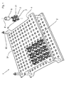
- FIG. 1 a first embodiment of a receiving body 2 is shown in a holding device 1.
- the holding device 1 consists of at least two stackable support platforms 4, which are supported by means of four spacers 32 which are arranged in the corner regions of the support plate 4 and fixed there, to each other.
- a plurality of receiving openings 31 are incorporated, in each of which a receiving body 2 is einklippsbar or inserted.
- the receiving body 2 is to be attached to the support plate 4 in a position-oriented manner and by this means isolated objects 5, for example screws, Nuts, tools or the like kept and stored for transport and processing purposes.
- the respective receiving body 2, and this is particularly in the FIGS. 2a and 2 B can be seen, consists essentially of a bottom 7, are attached to the four perpendicularly projecting from this holding finger 9.
- the retaining fingers 9 and the bottom 7 include an externally accessible space 13, in which the respective objects 5 can be inserted.
- one or more circumferential support ribs 14 may be provided, so that the retaining fingers 9 are mutually supported against each other and therefore can not bend inward or outward.
- each two webs 11 of two adjacent receiving body 2 are thus directed towards each other and form a receiving space 12 through which the article 5 is held stored such that the article 5 is accessible only from an opposite end of the bottom 7 through an insertion 17.
- the webs 11 of the receiving body 2 are L-shaped or T-shaped in cross section in the longitudinal direction 8, so that a plurality of projecting from the lateral surface 10 of the receiving body 2 paragraphs 15 are formed.
- the shoulder 15 is aligned in a plane parallel to and spaced from the bottom 7 and forms, together with the paragraphs 15 of the adjacent receiving body 2, a horizontal bearing for the article 5 in the receiving space 12, the four directed to the center of the receiving body 2 webs 11 and the heels 15 of which form a horizontal support for the object 5 in the space 13.
- the shoulders 15 may lie in a common plane with the floor 7 or in a plane parallel and spaced from the floor 7.
- the receiving body 2 and its retaining fingers 9 and the webs 11 are dimensioned such that the space formed by the one or more retaining fingers 9 13 is geometrically identical to the receiving space 12 formed.
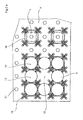
- FIG. 3 a second embodiment of a receiving body 2 is shown in a holding device 1.
- a plurality of receiving openings 31 is incorporated, in each of which a receiving body 2 is einklippsbar.
- two opposing slots 33 are provided in each case, which cooperate with the receiving body 2 and act as an anti-rotation.
- From the bottom 7 of the receiving body 2 are perpendicular to and parallel to the longitudinal axis 8 from holding fingers 9, which are connected by annular support ribs 14 together and together with the holding fingers 9 form an insertion 17.
- the holding fingers 9 and the bottom 7 enclose the space 13, which is accessible only from an end face opposite the bottom 7, the insertion opening 17 for positioning the object 5.
- On the outside of the lateral surface 10 four webs 11 are integrally formed over the circumference in a uniform angular pitch.
- the webs 11 of four adjacent receiving bodies 2 form a receiving space 12, which is formed around the center 21 of the four receiving body 2.
- the webs 11 of the four arranged in a square receiving body 2 are aligned with each other and have in the longitudinal axis 8 on an L-shaped or T-shaped cross-sectional shape. As a result, a shoulder 15 is formed, is held by an object 5 spaced from the support plate 4.
- FIG. 3a From the FIG. 3a is a development of the receiving body 2 according to FIG. 3 refer to.
- Four retaining fingers 9 are perpendicular from the bottom 7 aligned to the longitudinal axis 8 and form together with the bottom 7 a space 13.
- the support ribs 14 together with the holding fingers 9 an insertion opening 17 through which the object 5 can be inserted into the space 13.
- On the lateral surface 10 a plurality of outwardly projecting into the space 13 paragraphs 15 are formed, which are arranged in a plane parallel and spaced from the plane of the bottom 7.
- receiving bodies 2 arranged adjacently in a plane on the carrier plate 4 form a receiving space 12 whose center 21 corresponds to the geometric center of the four receiving bodies 2.
- the object 5 inserted into the receiving space 12 is held horizontally by the holding fingers 9 and the supporting ribs 14, respectively, and horizontally supported by the shoulders 15 facing each other.
- the receiving space 12 is geometrically identical to the space 13 formed by the holding fingers 9.
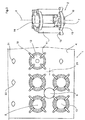
- FIG. 4 Shown is a receiving body composite 3, which is made in one piece from four receiving bodies 2 in an injection molding process.
- the respective receiving body composite 3 consists essentially of four interconnected receiving bodies 2, at the bottom 7, and in contrast to the region from which the retaining fingers 9 protrude, a base 16 is formed, through which the receiving body composite 3 on the support plate 4 and in Interaction with the receiving openings 31 can be fixed.
- projecting webs 11 are respectively formed on the lateral surface 10 of the receiving body 2 from the lateral surface. In the longitudinal direction 8, the webs 11 in cross-section L- or T-shaped, so that paragraphs 15 are formed.
- a receiving space 13 is formed, through which the article 5 is held stored such that this exclusively from the bottom 7 opposite end face is accessible through an insertion opening 17.
- the receiving body composite 3 may be integrally formed with the support plate 4 as a molded part. Also, a receiving body composite 3 may be formed from a plurality of receiving bodies 2, which are positively or non-positively connected by a connecting element 19. Such a development of the receiving body composite is the FIG. 4a refer to.
- the connecting elements 19 are arranged on the shoulders 15 such that a plurality of receiving bodies 2 or isolatedachi redesignunde 3 form a composite receiving body composite 3.
- Such a receiving body composite 3 may have one or more pedestals 16, by which the receiving body composite 3 is fixed to the support plate 4.
- the receiving body composite 3 may be formed from a composite of at least two receiving bodies 2 arranged in pairs. A receiving body composite 3 with four or more receiving bodies 2 has proved to be advantageous.
- FIG. 5 the arrangement of the receiving body composite 3 can be seen.
- the arranged on the support plate 4 receiving body composites 3 are aligned with each other so that the webs 11 of the respective receiving body 2 of the receiving body composite 3 and theracanalysisverbunde 3 form one or more receiving spaces 12.
- the geometric dimensions of the spaces 13 formed by the holding fingers 9 of the receiving body 2 are identical to the geometric dimensions of the receiving spaces 12 formed.
- FIGS. 6a and 6b Different bases are to be taken as locking devices or torsion-fuses, which cooperate with the receiving openings 31 of the support plate 4.
- the FIG. 6a are three receiving body 2 can be seen, each having different types of base 16.
- the base 16 may be formed as a thread 25, as a clip connection 26 or as Einrastfuß 27, through which the receiving body is attached to the support plate.
- the receiving openings 31 of the support plate 4 are arranged adjacent to each other in the embodiments such that four receiving openings 31 form a square.
- the receiving body 2 and the receiving body composite 3 can therefore be arranged adjacent to each other in pairs or in a square arrangement. Further geometric patterns, in particular an isosceles triangle, a rectangle or the like, for the arrangement of the receiving openings 31 or the receiving body 2 or the receiving body composite 3 to form further receiving spaces 12 are possible.
- the respectively formed receiving spaces 12 may also have different geometric dimensions than the spaces 13. This is particularly advantageous if articles 5 with different geometric dimensions in the respective receiving spaces 12 and spaces 13 should be used.
- the paragraphs 15 of the webs 11 may be arranged in different spaced planes parallel to the bottom 7 in order to vary the height of the spaces 13 and the receiving spaces 12.
- the paragraphs 15, which protrude from the lateral surface 10 of the receiving body 12 and the receiving body composite 3, can also be designed as around the receiving body 2 and the receiving body composite 3 circumferential annular shoulder 15.
- the heel 15 thus formed may be disposed in the plane of the floor 7 or be parallel to and spaced from the floor 7 in a plane. A position-oriented fixation on the support plate 4 is thus not required.
Abstract
Bei einem Aufnahmekörper Aufnahmekörper (2) zur Halterung eines Gegenstandes (5), beispielsweise eines Werkstückes, bestehend aus einem Boden (7) und aus mindestens einem an diesem angebrachten und von diesem senkrecht in eine Richtung abstehenden Haltefinger (9), der oder die gemeinsam mit dem Boden (7) einen Raum (13) einschließen, der von einer dem Boden (7) gegenüberliegenden Stirnseite von außen zur Positionierung des Gegenstandes (5) zugänglich ist, soll dieser in einer beliebigen Ausgestaltung der Außen- und Innenkontur in einem Spritzgussverfahren herstellbar sein. Dies wird dadurch erreicht, dass mindestens ein Steg (11) an der äußeren Mantelfläche (10) des Aufnahmekörpers (2) angeformt oder angebracht ist, dass mindestens zwei in einer Ebene benachbart angeordnete Aufnahmekörper (2) bzw. deren nach außen abstehenden Stege (11) einen Aufnahmeraum (12) bilden oder einschließen, in den ein Gegenstand (5) einsetzbar ist.In a receiving body receiving body (2) for holding an object (5), for example, a workpiece, consisting of a bottom (7) and at least one attached thereto and perpendicular from this in one direction projecting retaining fingers (9), the or together with the bottom (7) include a space (13) which is accessible from an opposite end of the bottom (7) from the outside for positioning of the article (5), this is to be produced in an arbitrary embodiment of the outer and inner contour in an injection molding process be. This is achieved in that at least one web (11) on the outer lateral surface (10) of the receiving body (2) is formed or attached, that at least two adjacent in a plane receiving body (2) or their outwardly projecting webs (11 ) form or enclose a receiving space (12) into which an article (5) can be inserted.
Description
Die Erfindung bezieht sich auf eine Vorrichtung mit einer Vielzahl von Aufnahmekörpern nach dem Oberbegriff der Patentansprüche 1, 6 und 13.The invention relates to a device with a plurality of receiving bodies according to the preamble of
Derartige Vorrichtungen haben die Aufgabe, diverse Werkstücke, beispielsweise Schrauben, rotations- oder nichtrotationssymmetrische Wellen, Rohre, Zapfen oder dgl., zu vereinzeln, um diese nach der spanabhebenden Bearbeitung zu reinigen, zu beschichten oder zu transportieren. Zu diesem Zweck werden insbesondere von der Kunststoffindustrie Körbe sogenannte Aufnahmekörper zur Verfügung gestellt, in die das jeweilige Werkstück einlegbar oder einsetzbar ist.Such devices have the task of various workpieces, such as screws, rotationally or non-rotationally symmetrical waves, tubes, pins or the like. To separate, to clean them after machining, to coat or to transport. For this purpose, baskets so-called receiving body are provided in particular by the plastics industry, in which the respective workpiece can be inserted or used.
Aus der
Nachteiliger Weise sind die vereinzelten Aufnahmekörper separat an das Gitterblech oder die Trägerplatte zu befestigen, so dass eine bestimmte Anzahl von Aufnahmekörpern an dem jeweiligen Gitterblech oder Trägerplatte montierbar ist. Die Bestückung eines Gitterbleches ist somit kostenintensiv und zeitaufwändig. Des Weiteren hat sich die konstruktive Gestaltung der Haltepfeiler als nachteilig erwiesen. Eine herstellungsbedingte Trennebene - die die positive und negative Form vorgeben - verläuft in der Längsrichtung des Aufnahmekörpers, so dass in einem Herstellungsprozess nur in Reihe angeordnete Aufnahmekörper herstellbar sind.Disadvantageously, the isolated receiving bodies are to be fastened separately to the grid plate or the carrier plate, so that a certain number of receiving bodies can be mounted on the respective grid plate or carrier plate. The assembly of a grid plate is thus costly and time consuming. Furthermore, the structural design of the retaining pillars has proved to be disadvantageous. A manufacturing-related parting plane - which specify the positive and negative shape - runs in the longitudinal direction of the receiving body, so that in a manufacturing process only arranged in series receiving body can be produced.
Durch die
Derartige Aufnahmekörper haben sich als Haltesystem zur Vereinzelung von hochwertigen Werkstücken bewährt und sind vielseitig einsetzbar, da die Größe des Aufnahmekörpers an die Außenkontur des aufzunehmenden Werkstückes angepasst werden kann. Eine Vielzahl von Aufnahmekörpern kann in einer einheitlichen Ausgestaltung hergestellt werden. Nachteilig ist jedoch, dass in der Herstellung in einem Spitzgussverfahren große und aufwändige Formen verwendet werden müssen und somit die Kosten solcher Aufnahmekörper hoch anzusetzen sind. Des Weiteren ist die Nutzung des vorhandenen Raumes auf einer Trägerplatte oder Gitterplatte nicht optimal, da Zwischenräume von benachbarten Aufnahmekörpern zu dessen Befestigung notwendig sind. Diese Zwischenräume jedoch sind zur Aufnahme von Gegenständen oder Werkstücken nicht nutzbar, so dass folglich diese Zwischenräume auf der Trägerplatte teilweise ungenutzt und somit verloren sind.Such receiving body have proven to be a holding system for separating high-quality workpieces and are versatile, since the size of the receiving body can be adapted to the outer contour of the male workpiece. A plurality of receiving bodies can be produced in a uniform configuration. The disadvantage, however, is that large and expensive molds have to be used in the production in an injection-molding process, and thus the costs of such receiving bodies are high. Furthermore, the use of the existing space on a support plate or grid plate is not optimal because interstices of adjacent receiving bodies are necessary for its attachment. However, these spaces are not available for receiving objects or workpieces, so that consequently these spaces on the support plate are partially unused and thus lost.
Es ist daher Aufgabe der Erfindung, den eingangs genannten Aufnahmekörper bzw. Aufnahmekörperverbund derart weiterzubilden, dass dieser in einer beliebigen Anzahl und nahezu beliebigen räumlichen Ausdehnung in einem Kunststoffspitzgussverfahrenschritt herstellbar ist, und dass die verfügbare Lagerfläche auf einer Trägerplatte optimal ausgenutzt ist und gleichzeitig der Aufnahmekörper zuverlässig und verdrehsicher in einer oder mehreren Aufnahmeöffnungen, die in einem Gitterblech oder einer Trägerplatte eingearbeitet sind, arretierbar ist, um sowohl die Herstellung als auch die Montagekosten zu reduzieren.It is therefore an object of the invention to develop the above-mentioned receiving body or receiving body composite such that it can be produced in any number and almost any spatial extent in a Kunststoffspitzgussverfahrenschritt, and that the available storage space is optimally utilized on a support plate and at the same time the receiving body reliable and secured against rotation in one or more receiving openings, which are incorporated in a grid plate or a carrier plate, can be locked in order to reduce both the production and the installation costs.
Diese Aufgabe ist erfindungsgemäß durch die Merkmale des kennzeichnenden Teils der Patentansprüche 1, 6 und 13 gelöst.This object is achieved by the features of the characterizing part of
Weitere vorteilhafte Weiterbildungen der Erfindung ergeben sich aus den Unteransprüchen.Further advantageous developments of the invention will become apparent from the dependent claims.
Dadurch, dass mindestens ein Steg an der äußeren Mantelfläche des Aufnahmekörpers angeformt oder angebracht ist, dass mindestens zwei in einer Ebene benachbart angeordnete Aufnahmekörper bzw. deren nach außen abstehenden Stege einen Aufnahmeraum bilden oder einschließen, in den ein Gegenstand einsetzbar ist oder dadurch, dass mindestens zwei Aufnahmekörper benachbart an der Trägerplatte angeordnet sind, dass zwischen den Aufnahmekörpern ein Aufnahmeraum gebildet ist, durch den der Gegenstand derart gelagert gehalten ist, dass der Gegenstand ausschließlich von einer dem Boden gegenüberliegenden Stirnseite zugänglich ist, oder dadurch, dass mindestens zwei der Aufnahmekörper eine einstückige Baueinheit bilden oder dass mindestens zwei der Aufnahmekörper mittels eines Verbindungselementes eine Baueinheit bilden, dass zwischen den Aufnahmekörpern dieser Baueinheit und/oder dass durch zwei benachbarte Baueinheiten ein oder mehrere Halteräume gebildet sind, durch die die Gegenstände derart gelagert gehalten sind, und dass die Gegenstände ausschließlich von einer dem Boden gegenüberliegenden Stirnseite zugänglich sind, ist die verfügbare Fläche auf einer Trägerplatte optimal ausgenutzt und die Herstellungskosten sowie Montagezeiten sind reduziert, da die Anzahl der aufnehmbaren Gegenstände erheblich erhöht ist, ohne dass weitere Herstellungskosten für zusätzliche Aufnahmekörper anfallen.Characterized in that at least one web is integrally formed or attached to the outer surface of the receiving body, that at least two adjacent arranged in a plane receiving body or its outwardly projecting webs form or include a receiving space in which an object is used or in that at least two receiving body adjacent to the support plate are arranged, that between the receiving bodies a receiving space is formed, by which the object is held stored so that the object is accessible only from a bottom opposite end face, or in that at least two of the receiving body is a one-piece Form assembly or that at least two of the receiving body by means of a connecting element form a unit that between the receiving bodies of this unit and / or that two adjacent units one or more holding spaces are formed by the Ge objects are stored in such a way, and that the objects are accessible only from the bottom opposite end, the available area on a carrier plate is optimally utilized and the manufacturing costs and assembly times are reduced, since the number of receivable objects is considerably increased without further Costs incurred for additional receiving body.
Aufgrund zahlreicher benachbart zueinander angeordneter Aufnahmekörper auf der Trägerplatte bilden sich zwischen mindestens zwei benachbarten Aufnahmekörpern durch die von der Mantelfläche nach außen abstehenden Stege räumliche Begrenzungen, die einen Aufnahmeraum bilden. Somit können nicht nur vereinzelte Gegenstände in einem Raum der durch einen Aufnahmekörper gebildet ist eingesetzt sein, sondern auch Gegenstände in die Aufnahmeräume zwischen mehreren Aufnahmekörper.Due to numerous adjacent to each other arranged receiving body on the support plate form between at least two adjacent receiving bodies by the projecting from the lateral surface outwardly webs spatial boundaries that form a receiving space. Thus, not only isolated objects in a space formed by a receiving body can be used, but also objects in the receiving spaces between several receiving body.
Dabei ist es besonders vorteilhaft, wenn vier der von der Mantelfläche des Aufnahmekörpers nach außen abstehenden Stege gleichmäßig über den Umfang verteilt sind und im Querschnitt X-förmig ausgestaltet sind. Somit sind zwei Stege zweier benachbarter Aufnahmekörper zueinander ausgerichtet, und bilden einen zusätzlichen Aufnahmeraum, in den ein Gegenstand eingesetzt werden kann. Dadurch ist zudem erreicht, dass durch vier in einem Rechteck angeordneten Aufnahmekörper insgesamt neun Gegenstände in den jeweils vier Räumen und fünf Aufnahmeräumen gelagert gehalten werden können. Somit können auf einer Trägerplatte mit sieben mal neun Reihen anstatt bisher 63 Gegenstände nunmehr 221 Gegenstände gelagert gehalten sein.It is particularly advantageous if four of the lateral surface of the receiving body outwardly projecting webs are distributed uniformly over the circumference and are configured in cross-section X-shaped. Thus, two webs of two adjacent receiving body aligned with each other, and form an additional receiving space into which an object can be inserted. As a result, it is also achieved that a total of nine items can be stored in the four rooms and five receiving spaces by four receiving bodies arranged in a rectangle. Thus, 221 objects can now be stored on a support plate with seven times nine rows instead of 63 items so far.
Weiterhin ist es besonders vorteilhaft die Stege im Querschnitt L- oder T-förmig auszugestalten. Dadurch ist nämlich ein Absatz parallel und beabstandet zu dem Boden des Aufnahmekörpers gebildet, durch den der Gegenstand beabstandet zu der Trägerplatte gelagert ist. Der Absatz sollte darüber hinaus in einer Ebene mit dem Boden des Aufnahmekörpers oder in einer Ebene angeordnet sein, die parallel und beabstandet zu dem Boden ausgerichtet ist, so dass die Gegenstände in dem Raum und in dem Aufnahmeraum in der gleichen Ebene gehalten sind. Der Absatz verhindert, dass der jeweilige Gegenstand nicht in Kontakt mit der Trägerplatte kommt. Die Trägerplatte ist oftmals aus einen harten und/oder metallischen Werkstoff gebildet, so dass beispielsweise ein Verkratzen der Gegenstände beim Transport oder auch eine elektrochemische Reaktion bei einem Kontakt verhindert ist.Furthermore, it is particularly advantageous to design the webs in cross-section L- or T-shaped. As a result, a shoulder is parallel and spaced from the bottom of the receiving body, through which the article is mounted at a distance from the carrier plate. The heel should also be arranged in a plane with the bottom of the receiving body or in a plane which is parallel and spaced from the ground, so that the objects in the space and in the receiving space are held in the same plane. The heel prevents the respective object from coming into contact with the carrier plate. The support plate is often formed from a hard and / or metallic material, so that, for example, a scratching of the objects during transport or even an electrochemical reaction during contact is prevented.
Auf der von dem Boden abgewandten Seite des Aufnahmekörpers ist ein Socken angeformt. Der Sockel am Aufnahmekörper dient der Arretierung des Aufnahmekörpers an der Trägerplatte. Der Abstand zwischen den Aufnahmekörper ist demnach durch den Abstand der Aufnahmeöffnungen in der Trägerplatte vorgegeben. Unter bestimmten geometrischen Voraussetzungen ist es demnach vorteilhaft, das drei oder vier Aufnahmekörper derart auf der Trägerplatte angeordnet sind, dass die Haltefinger einen Aufnahmeraum einschließen, durch den ein Gegenstand derart gehalten ist, dass dieser nur von der dem Boden gegenüberliegenden Seite in den Aufnahmeraum eingesetzt werden kann. An dem Aufnahmekörper können vorzugsweise am Boden Absätze angeformt sein, durch der Gegenstand parallel und beabstandet zu der Trägerplatte gehalten ist.On the side facing away from the bottom of the receiving body a sock is formed. The base on the receiving body serves to lock the receiving body to the support plate. The distance between the receiving body is therefore predetermined by the distance of the receiving openings in the carrier plate. Under certain geometrical conditions, it is therefore advantageous that three or four receiving body are arranged on the support plate, that the holding fingers include a receiving space through which an object is held such that it only from the opposite side of the ground in the receiving space can be used. On the receiving body paragraphs may preferably be integrally formed on the ground, is held by the object parallel and spaced from the support plate.
Darüber hinaus können mehrere Aufnahmekörper als ein Verbund von Aufnahmekörper ein oder mehrteilig ausgebildet sein. Vorteilhaft bei dem einstückigen Verbund von Aufnahmekörper ist, dass diese Baueinheit in einem Spritzgussverfahren hergestellt ist und der Fertigungsaufwand sowie der Montageaufwand auf einer Trägerplatte mit vielen Aufnahmekörpern reduziert ist. Zwischen den Aufnahmeköpern können Aufnahmeräume vorgesehen sein, so dass die verfügbare Fläche auf einer Trägerplatte bestmöglich ausgenutzt ist.In addition, a plurality of receiving body may be formed as a composite of receiving body or one or more parts. An advantage of the one-piece composite of receiving body is that this assembly is made in an injection molding process and the manufacturing cost and the assembly effort is reduced to a support plate with many receiving bodies. Receptacles can be provided between the receiving bodies, so that the available area on a carrier plate is utilized optimally.
Der Verbund von Aufnahmekörpern ist auch aus mehreren vereinzelten Aufnahmekörpern oder einstückigen Verbund von Aufnahmekörpern bildbar. An den Aufnahmekörper sind hierzu Verbindungselemente angeordnet durch diese die Aufnahmekörper miteinander form- oder kraftschlüssig aneinander befestigbar sind.The composite of receiving bodies can also be formed from a plurality of isolated receiving bodies or one-piece composite of receiving bodies. For this purpose, connecting elements are arranged on the receiving body by means of which the receiving bodies can be fastened to one another in a form-fitting or non-positive manner.
In der Zeichnung sind Haltevorrichtungen mit zwei erfindungsgemäßen Ausführungsbeispielen eines Aufnahmekörpers sowie ein Ausführungsbeispiel eines Aufnahmekörperverbundes dargestellt, die nachfolgend näher erläutert sind. Im Einzelnen zeigt:
Figur 1- ein erstes Ausführungsbeispiel eines Aufnahmekörpers in einer Haltvorrichtung, bestehend aus zwei Gitter- oder Trägerplatten in die jeweils eine Vielzahl von Aufnahmeöffnungen eingearbeitet sind, um in diesen jeweils einen Aufnahmekörper abzustützen, in den ein Gegenstand eingesetzt ist, in perspektivischer Ansicht,
- Figur 2a
- eine vergrößerte Darstellung der Aufnahmevorrichtung gemäß
Figur 1 - Figur 2b
- eine vergrößerte Darstellung der Aufnahmevorrichtung gemäß
Figur 1 Figur 3- eine zweites Ausführungsbeispiel eines Aufnahmekörpers in einer Haltevorrichtung gemäß
Figur 1 - Figur 3a
- eine Weiterbildung des Aufnahmekörpers gemäß
Figur 3 Figur 4- ein Ausführungsbeispiel eines Aufnahmekörperverbundes in einer Haltevorrichtung, bestehend aus zwei Gitter- oder Trägerplatten, in denen eine Vielzahl von Aufnahmeöffnungen eingearbeitet sind, um in diesen den Aufnahmekörperverbund abzustützen, in denen ein oder mehrere Gegenstände eingesetzt sind, in perspektivischer Ansicht,
- Figur 4a
- eine Weiterbildung des Aufnahmekörperverbundes gemäß
Figur 4 Figur 5- eine vergrößerte Darstellung des Aufnahmekörperverbundes gemäß
Figur 4 - Figur 6a
- den Aufnahmekörper gemäß
Figur 1 - Figur 6b
- den Verbund der Aufnahmekörper gemäß
Figur 5
- FIG. 1
- a first embodiment of a receiving body in a holding device, consisting of two grid or carrier plates in each of which a plurality of receiving openings are incorporated to support in each of these a receiving body in which an object is inserted, in perspective view,
- FIG. 2a
- an enlarged view of the receiving device according to
FIG. 1 on a carrier plate with a plurality of receiving bodies, which form receiving spaces, in perspective view, - FIG. 2b
- an enlarged view of the receiving device according to
FIG. 1 on a carrier plate, in plan view, - FIG. 3
- a second embodiment of a receiving body in a holding device according to
FIG. 1 . - FIG. 3a
- a development of the receiving body according to
FIG. 3 . - FIG. 4
- an embodiment of a receiving body composite in a holding device consisting of two grid or carrier plates in which a plurality of receiving openings are incorporated to support in this the receiving body composite in which one or more objects are used, in perspective view,
- FIG. 4a
- a development of the receiving body group according to
FIG. 4 , in perspective view, - FIG. 5
- an enlarged view of the receiving body composite according to
FIG. 4 , in plan view, - FIG. 6a
- the receiving body according to
FIG. 1 along a section through the center and three differently shaped sockets as a locking device and - FIG. 6b
- the composite of the receiving body according to
FIG. 5 along a cutting line through the center.
In
Der jeweilige Aufnahmekörper 2, und dies ist insbesondere in den
An der jeweiligen Mantelfläche 10 des Aufnahmekörpers 2 sind über den Umfang gleichmäßig im Abstand von 90° vier Stege 11 angeformt. Die im Querschnitt X-förmig ausgebildeten Stege 11 sind dabei derart an dem Aufnahmekörper 2 angeordnet, dass drei von vier Stegen 11 aus dem Aufnahmekörper 2 herausstehen und der vierte Steg 11 auf den Mittelpunkt des Aufnahmekörpers 2 gerichtet ist. Mehrere Aufnahmekörper 2 sind auf der Trägerplatte 4 in parallel zueinander und ausgerichteten Reihen äquidistant beabstandet angeordnet. Jeweils zwei Stege 11 zweier benachbarter Aufnahmekörper 2 sind somit zueinander gerichtet und bilden einen Aufnahmeraum 12, durch den der Gegenstand 5 derart gelagert gehalten ist, dass der Gegenstand 5 ausschließlich von einer dem Boden 7 gegenüberliegenden Stirnseite durch eine Einsetzöffnung 17 zugänglich ist.At the respective lateral surface 10 of the receiving
Die Stege 11 des Aufnahmekörpers 2 sind im Querschnitt in der Längsrichtung 8 L-oder T-förmig ausgestaltet, so dass mehrere von der Mantelfläche 10 des Aufnahmekörpers 2 abstehende Absätze 15 gebildet sind. Der Absatz 15 ist in einer Ebene parallel und beabstandet zu dem Boden 7 ausgerichtet und bildet zusammen mit den Absätzen 15 der benachbarten Aufnahmekörper 2 eine horizontale Lagerung für den Gegenstand 5 in dem Aufnahmeraum 12. Die vier auf den Mittelpunkt des Aufnahmekörpers 2 gerichteten Stege 11 bzw. deren Absätze 15 bilden eine horizontale Lagerung für den Gegenstand 5 in dem Raum 13. Die Absätze 15 können in einer gemeinsamen Ebene mit dem Boden 7 oder in einer Ebene, die parallel und beabstandet zu dem Boden 7 angeordnet ist, liegen.The
Bei gegebenem Abstand der Aufnahmeöffnungen 31 in der Trägerplatte 4 sind die Aufnahmekörper 2 bzw. deren Haltefinger 9 und die Stege 11 derart zu bemessen, dass der durch die oder den Haltefinger 9 gebildete Raum 13 geometrisch identisch ist mit dem gebildeten Aufnahmeraum 12.At a given distance of the receiving
Dadurch ist erreicht, dass durch vier auf einer Trägerplatte 4 angeordnete Aufnahmekörper fünf Aufnahmeräume 12 gebildet sind, so dass in diesen Verbund von Aufnahmekörpern insgesamt neun geometrisch identische Aufnahmeräume 12 entstehen, ohne dass hierfür zusätzliche Herstellungskosten anfallen. Bei einer typischen Trägerplatte mit 9 x 7 Reihen, folglich 63 Aufnahmeöffnungen 31, sind somit 158 Aufnahmeräume 12 gebildet. Demnach können auf einer derartigen Trägerplatte 4 insgesamt 221 Gegenstände eingesetzt werden.It is thereby achieved that five receiving
In der
Von dem Boden 7 des Aufnahmekörpers 2 stehen senkrecht parallel und beabstandet zu der Längsachse 8 Haltefinger 9 ab, die durch ringförmige Stützrippen 14 miteinander verbunden sind und gemeinsam mit den Haltefingern 9 eine Einsetzöffnung 17 bilden. Die Haltefinger 9 und der Boden 7 schließen den Raum 13 ein, der ausschließlich von einer dem Boden 7 gegenüberliegenden Stirnseite, der Einsetzöffnung 17 zur Positionierung des Gegenstandes 5 zugänglich ist. An der Außenseite der Mantelfläche 10 sind über dem Umfang in gleichmäßiger Winkelteilung vier Stege 11 angeformt. Die Stege 11 von vier benachbarten Aufnahmekörpern 2 bilden einen Aufnahmeraum 12, der um den Mittelpunkt 21 der vier Aufnahmekörper 2 gebildet ist. Die Stege 11 der vier in einem Quadrat angeordneten Aufnahmekörper 2 sind zueinander ausgerichtet und weisen in der Längsachse 8 eine L- oder T-förmige Querschnittsform auf. Dadurch ist ein Absatz 15 gebildet, durch den ein Gegenstand 5 beabstandet zu der Trägerplatte 4 gelagert gehalten ist.From the
Aus der
Vier in einer Ebene auf der Trägerplatte 4 benachbart angeordnete Aufnahmekörper 2 bilden einen Aufnahmeraum 12, dessen Mittelpunkt 21 dem geometrischen Mittelpunkt der vier Aufnahmekörper 2 entspricht. Der in den Aufnahmeraum 12 eingesetzte Gegenstand 5 ist durch die Haltefinger 9 bzw. die Stützrippen 14 seitlich und in der horizontalen durch die aufeinander zugewandten Absätze 15 horizontal gelagert gehalten.Four receiving
Vier in einem Quadrat auf einer Trägerplatte 4 angeordneten Aufnahmeköpern 2 bilden oder schließen jeweils einen Aufnahmeraum 12 ein. Der Aufnahmeraum 12 ist dabei geometrisch identisch mit dem durch die Haltefinger 9 gebildete Raum 13.Four arranged in a square on a
Ein weiteres Ausführungsbeispiel ist der
Der Aufnahmekörperverbund 3 kann mit der Trägerplatte 4 einstückig als Spitzgussteil ausgebildet sein. Auch kann ein Aufnahmekörperverbund 3 aus einer Vielzahl von Aufnahmekörpern 2 gebildet sein, die durch ein Verbindungselement 19 miteinander form- oder kraftschlüssig verbunden sind. Eine derartige Weiterbildung des Aufnahmekörperverbundes ist der
Ein derartiger Aufnahmekörperverbund 3 kann ein oder mehrere Sockel 16 aufweisen, durch die der Aufnahmekörperverbund 3 an der Trägerplatte 4 fixiert ist. Der Aufnahmekörperverbund 3 kann aus einem Verbund von mindestens zwei paarweise angeordneten Aufnahmekörpern 2 gebildet sein. Ein Aufnahmekörperverbund 3 mit vier oder mehreren Aufnahmekörpern 2 hat sich als vorteilhaft erwiesen.Such a receiving
Insbesondere der
Den
Die Aufnahmeöffnungen 31 der Trägerplatte 4 sind in den Ausführungsbeispielen derart zueinander benachbart angeordnet, dass vier Aufnahmeöffnungen 31 ein Quadrat bilden. Die Aufnahmekörper 2 und auch der Aufnahmekörperverbund 3 können demnach paarweise oder in quadratischer Anordnung zueinander benachbart angeordnet sein. Weitere geometrische Muster, insbesondere ein gleichschenkliges Dreieck, ein Rechteck oder dergleichen, zur Anordnung der Aufnahmeöffnungen 31 bzw. der Aufnahmekörper 2 oder des Aufnahmekörperverbundes 3 zur Bildung weiterer Aufnahmeräume 12 sind möglich.The receiving
Die jeweils gebildeten Aufnahmeräume 12 können auch andere geometrischen Abmessungen als die Räume 13 aufweisen. Dies ist insbesondere dann vorteilhaft, wenn Gegenstände 5 mit unterschiedlichen geometrischen Abmessungen in die jeweiligen Aufnahmeräume 12 und Räume 13 einsetzbar seien sollen. Dabei können auch die Absätze 15 der Stege 11 in unterschiedliche beabstandeten Ebenen parallel zum Boden 7 angeordnet sein, um die Höhe der Räume 13 und der Aufnahmeräume 12 zu variieren.The respectively formed receiving
Die Absätze 15, die aus der Mantelfläche 10 des Aufnahmekörpers 12 bzw. des Aufnahmekörperverbundes 3 herausstehen, können auch als um den Aufnahmekörper 2 bzw. den Aufnahmekörperverbundes 3 umlaufender ringförmiger Absatz 15 ausgebildet sein. Der derart gebildete Absatz 15 kann in der Ebene des Bodens 7 angeordnet sein oder in einer Ebene parallel und beabstandet zu dem Boden 7 sein. Eine lageorientlerte Fixierung an der Trägerplatte 4 ist somit nicht erforderlich.The
Die unterschiedlichen Ausführungsbeispiele einer erfindungsgemäßen Ausführung eines Aufnahmekörpers 2, bzw. einer Haltevorrichtung 1 und eines Aufnahmekörperverbundes 3 können miteinander kombiniert werdenThe different embodiments of an inventive embodiment of a receiving
Claims (17)
dadurch gekennzeichnet,
dass mindestens ein Steg (11) an der äußeren Mantelfläche (10) des Aufnahmekörpers (2) angeformt oder angebracht ist, dass mindestens zwei in einer Ebene benachbart angeordnete Aufnahmekörper (2) bzw. deren nach außen abstehenden Stege (11) einen Aufnahmeraum (12) bilden oder einschließen, in den ein Gegenstand (5) einsetzbar ist.Receiving body (2) for holding an object (5), for example a workpiece, consisting of a bottom (7) and at least one attached thereto and perpendicularly projecting in one direction retaining fingers (9), the or together with the ground (7) include a space (13) accessible from outside the bottom (7) from the outside for positioning the article (5),
characterized,
in that at least two receiving bodies (2) arranged adjacently in a plane or their outwardly projecting webs (11) have at least one web (11) on the outer lateral surface (10) of the receiving body (2), or formed, a receiving space (12 ) in which an article (5) can be inserted.
dadurch gekennzeichnet,
dass die Stege (11) des Aufnahmekörpers (2) im Querschnitt in Längsrichtung (8) L- oder T-förmig ausgestaltet sind, dass ein von der Mantelfläche (10) des Aufnahmekörpers (2) abstehender Absatz (15) gebildet ist, und dass der Absatz (15) in der Ebene des Bodens (7) oder in einer Ebene, die parallel und beabstandet zu dem Boden (7) ist, ausgerichtet ist.Receiving body (2) according to claim 1
characterized,
that the webs (11) of the receiving body (2) in cross-section in the longitudinal direction (8) L- or T-shaped are configured such that a from the outer surface (10) of the receiving body (2) projecting shoulder (15) is formed, and that the step (15) is aligned in the plane of the floor (7) or in a plane parallel and spaced from the floor (7).
dadurch gekennzeichnet,
dass die Stege (11) des Aufnahmekörpers (2) im Querschnitt T-, I-, Y, oder X-förmig ausgebildet sind.Receiving body (2) according to one of the preceding claims
characterized,
in that the webs (11) of the receiving body (2) are T-shaped, I-shaped, Y-shaped or X-shaped in cross-section.
dadurch gekennzeichnet,
dass der Aufnahmekörper (2) aus ein oder mehreren Haltefingern (9) gebildet ist, und dass zwei benachbarte Haltefinger (9) durch eine Stützrippe (14) miteinander verbunden sind.Receiving body (2) according to one of the preceding claims
characterized,
in that the receiving body (2) is formed from one or more retaining fingers (9), and that two adjacent retaining fingers (9) are interconnected by a supporting rib (14).
dadurch gekennzeichnet,
dass die Stege (11) des Aufnahmekörpers (2) an der Mantelfläche (10) über den Umfang gleichmäßig verteilt sind, vorzugsweise in einer Winkelteilung von 90° oder 120° um den Mittelpunkt (21) des Aufnahmekörpers (2).Receiving body (2) according to one of the preceding claims
characterized,
that the webs (11) of the receiving body (2) on the lateral surface (10) are distributed uniformly over the circumference, preferably in an angular pitch of 90 ° or 120 ° about the center (21) of the receiving body (2).
dadurch gekennzeichnet,
dass mindestens zwei Aufnahmekörper (2) benachbart an der Trägerplatte (4) angeordnet sind, dass zwischen den Aufnahmekörpern (2) ein Aufnahmeraum (12) gebildet ist, durch den der Gegenstand (5) derart gelagert gehalten ist, dass der Gegenstand (5) ausschließlich von einer dem Boden (7) gegenüberliegenden Stirnseite zugänglich ist.Holding device (1) for isolated objects (5) for their processing and transport, consisting of a plurality of receiving bodies (2), in particular of receiving bodies (2) according to one of claims 1 to 5, wherein the respective Receiving body (2) from a bottom (7) and at least one attached thereto and projecting perpendicularly from this in one direction retaining finger (9) is formed, which together with the bottom (7) includes a space (13), of a the bottom (7) opposite end face from the outside for positioning of the object (5) is accessible and formed on the end facing away from the space (13) molded or attached base (16) through which the respective receiving body (2) on a support plate (4 ) is lockable,
characterized,
in that at least two receiving bodies (2) are arranged adjacent to the carrier plate (4), that a receiving space (12) is formed between the receiving bodies (2), by which the article (5) is held in such a manner that the article (5) is accessible only from a bottom (7) opposite end face.
dadurch gekennzeichnet,
dass der jeweilige Aufnahmeraum (12) eine Einsetzöffnung (17) aufweist, die in der gleichen Ebene der jeweils benachbarten Aufnahmekörper (2) liegt, und dass durch die Einsetzöffnung (17) der Gegenstand (5) in den Aufnahmeraum (12) einsetzbar ist.Holding device (1) according to claim 6
characterized,
in that the respective receiving space (12) has an insertion opening (17) which lies in the same plane of the respectively adjacent receiving body (2), and that the object (5) can be inserted into the receiving space (12) through the insertion opening (17).
dadurch gekennzeichnet,
dass die jeweilige Innenkontur des Aufnahmeraums (12) geometrisch identisch mit der Innenkontur des durch die Haltefinger (9) des Aufnahmekörpers (2) eingeschlossen Raumes (13) ist.Holding device (1) according to claim 6 or 7
characterized,
that the respective inner contour of the receiving space (12) geometrically identical to the inner contour of by the retaining fingers (9) of the receiving body (2) enclosed space (13).
dadurch gekennzeichnet,
dass ein oder mehrere Stege (11) an der äußeren Mantelfläche (10) des Aufnahmekörpers (2) angeformt sind, und dass die Stege (11) zweier benachbarter Aufnahmekörper (2) von einen gemeinsamen Mittelpunkt (21) den identischen Abstand aufweisen und diesem zugeordnet sind.Holding device (1) according to one of claims 6 to 8
characterized,
in that one or more webs (11) are integrally formed on the outer lateral surface (10) of the receiving body (2), and that the webs (11) of two adjacent receiving bodies (2) have the identical spacing from and assigned to a common center (21) are.
dadurch gekennzeichnet,
dass in die Trägerplatte (4) Aufnahmeöffnungen (31) eingebracht sind, dass die Aufnahmeöffnungen (31) reihenweise und äquidistant zueinander angeordnet sind und dass mehrere Reihen von Aufnahmeöffnungen (31) parallel und zueinander ausgerichtet verlaufen, oder dass drei benachbarte Aufnahmeöffnungen (31) in zwei unterschiedlichen Reihen ein gleichschenkliges Dreieck bilden.Holding device (1) according to one of claims 6 to 9
characterized,
that receiving openings (31) are introduced into the carrier plate (4), that the receiving openings (31) are arranged in rows and equidistant from one another and that a plurality of rows of receiving openings (31) are parallel and aligned, or that three adjacent receiving openings (31) are in two different rows form an isosceles triangle.
dadurch gekennzeichnet,
dass die Aufnahmekörper (2) jeweils mindestens einen Absatz (15) aufweisen, und dass der Gegenstand (5) in dem Aufnahmeraum (12) durch die Absätze (15) beabstandet zu der Trägerplatte (4) gehalten ist.Holding device (1) according to one of claims 6 to 10
characterized,
in that the receiving bodies (2) each have at least one shoulder (15), and in that the article (5) is held in the receiving space (12) at a distance from the carrier plate (4) by the shoulders (15).
dadurch gekennzeichnet,
dass an dem jeweiligen Absatz (15) des Aufnahmekörpers (2) ein Zentrierfinger angeordnet ist und dass die Zentrierfinger mehrerer benachbarter Aufnahmekörper (2) für den Gegenstand (5) eine Zentrierung bilden.Holding device (1) according to one of claims 6 to 11
characterized,
in that a centering finger is arranged on the respective shoulder (15) of the receiving body (2) and that the centering fingers of a plurality of adjacent receiving bodies (2) form a centering for the object (5).
dadurch gekennzeichnet,
dass mindestens zwei der Aufnahmekörper (2) eine einstückige Baueinheit bilden oder dass mindestens zwei der Aufnahmekörper (2) mittels eines Verbindungselementes (19) eine Baueinheit bilden, dass zwischen den Aufnahmekörpern (2) dieser Baueinheit und/oder dass durch zwei benachbarte Baueinheiten ein oder mehrere Halteräume (20) gebildet sind, durch die die Gegenstände (5) derart gelagert gehalten sind, und dass die Gegenstände (5) ausschließlich von einer dem Boden (7) gegenüberliegenden Stirnseite zugänglich sind.Receiving body assembly (3), in particular formed from a plurality of receiving bodies (2) according to one of claims 1 to 5, for the transport of objects (2) position-oriented with at least one mounting base (16) on a support plate (4) can be fastened and locked,
characterized,
that at least two of the receiving bodies (2) form an integral unit or that at least two of the receiving body (2) by means of a connecting element (19) form a structural unit, that between the receiving bodies (2) of this unit and / or that by two adjacent units one or a plurality of retaining spaces (20) are formed, by which the objects (5) are held in such a manner, and that the objects (5) are accessible only from a bottom (7) opposite end face.
dadurch gekennzeichnet,
dass an der äußeren Mantelfläche (10) der Aufnahmekörper (2) ein oder mehrere Stege (11) angeordnet sind, und/oder dass die Stege (11) zweier benachbarter Aufnahmekörper (2) miteinander verbunden sind.Receiving body assembly (3) according to claim 13,
characterized,
in that one or more webs (11) are arranged on the outer lateral surface (10) of the receiving body (2), and / or that the webs (11) of two adjacent receiving bodies (2) are connected to one another.
dadurch gekennzeichnet,
dass an der äußeren Mantelfläche (10) der Aufnahmekörper (2) ein oder mehrere Absätze (15) angeordnet sind, und/oder dass die Absätze (15) zweier benachbarter Aufnahmekörper (2) miteinander verbunden sind.Receiving body assembly (3) according to claim 13 or 14,
characterized,
in that one or more shoulders (15) are arranged on the outer lateral surface (10) of the receiving body (2), and / or that the shoulders (15) of two adjacent receiving bodies (2) are connected to one another.
dadurch gekennzeichnet,
dass das Verbindungselement (19) jeweils zwei oder mehrere Aufnahmekörper (2) bzw. Aufnahmekörperverbunde (3) mit einer formschlüssigen Wirkverbindung verbindet.Receiving body assembly (3) according to one of claims 13 to 15,
characterized,
that the connecting element (19) in each case connects two or more receiving bodies (2) or receiving body composites (3) with a form-locking operative connection.
dadurch gekennzeichnet,
dass der Verbund von Aufnahmekörper (2) und die Trägerplatte (4) einstückig sind.Receiving body assembly (3) according to one of claims 13 to 16
characterized,
that the composite of receiving body (2) and the support plate (4) are integral.
Priority Applications (1)
| Application Number | Priority Date | Filing Date | Title |
|---|---|---|---|
| EP15166236.8A EP2952440B1 (en) | 2014-06-03 | 2015-05-04 | Receiving body, holding device comprising receiving bodies and device comprising groups of receiving bodies |
Applications Claiming Priority (2)
| Application Number | Priority Date | Filing Date | Title |
|---|---|---|---|
| EP14170882.6A EP2952439B1 (en) | 2014-06-03 | 2014-06-03 | Carrier assembly |
| EP15166236.8A EP2952440B1 (en) | 2014-06-03 | 2015-05-04 | Receiving body, holding device comprising receiving bodies and device comprising groups of receiving bodies |
Publications (2)
| Publication Number | Publication Date |
|---|---|
| EP2952440A1 true EP2952440A1 (en) | 2015-12-09 |
| EP2952440B1 EP2952440B1 (en) | 2017-07-19 |
Family
ID=50884717
Family Applications (2)
| Application Number | Title | Priority Date | Filing Date |
|---|---|---|---|
| EP14170882.6A Active EP2952439B1 (en) | 2014-06-03 | 2014-06-03 | Carrier assembly |
| EP15166236.8A Active EP2952440B1 (en) | 2014-06-03 | 2015-05-04 | Receiving body, holding device comprising receiving bodies and device comprising groups of receiving bodies |
Family Applications Before (1)
| Application Number | Title | Priority Date | Filing Date |
|---|---|---|---|
| EP14170882.6A Active EP2952439B1 (en) | 2014-06-03 | 2014-06-03 | Carrier assembly |
Country Status (1)
| Country | Link |
|---|---|
| EP (2) | EP2952439B1 (en) |
Cited By (6)
| Publication number | Priority date | Publication date | Assignee | Title |
|---|---|---|---|---|
| CN109367968A (en) * | 2018-12-05 | 2019-02-22 | 盐城远大金属科技有限公司 | A kind of cam special tooling |
| USD945735S1 (en) | 2019-05-15 | 2022-03-08 | Chep Technology Pty Limited | Part for a pallet |
| USD949509S1 (en) | 2019-05-15 | 2022-04-19 | Chep Technology Pty Limited | Part for a pallet |
| USD951580S1 (en) | 2019-05-15 | 2022-05-10 | Chep Technology Pty Limited | Part for a pallet |
| US11542062B2 (en) | 2017-11-16 | 2023-01-03 | Chep Technology Pty Limited | Pallet with support modules |
| WO2023104979A1 (en) * | 2021-12-08 | 2023-06-15 | Zell Systemtechnik Gmbh | Workpiece support |
Families Citing this family (3)
| Publication number | Priority date | Publication date | Assignee | Title |
|---|---|---|---|---|
| IT201700087388A1 (en) | 2017-07-28 | 2019-01-28 | Ferremi Luca S R L A Socio Unico | PIECE HOLDER SYSTEM FOR INDUSTRIAL USE |
| SG11202011105VA (en) * | 2018-05-08 | 2020-12-30 | Choon Sen David Lam | A divider and divider plate |
| DE102019135183A1 (en) * | 2019-12-19 | 2021-06-24 | Oerlikon Surface Solutions Ag, Pfäffikon | Holding system for holding substrates |
Citations (7)
| Publication number | Priority date | Publication date | Assignee | Title |
|---|---|---|---|---|
| FR1365477A (en) * | 1963-05-22 | 1964-07-03 | Vitherm | Advanced bottle rack |
| US5660279A (en) * | 1992-07-29 | 1997-08-26 | Rehrig Pacific Company, Inc. | Stackable low depth bottle case |
| DE202012103711U1 (en) * | 2012-09-27 | 2012-11-15 | Ingo Zell | Support plate of a workpiece carrier system and workpiece carrier system |
| EP2570234A1 (en) * | 2011-09-13 | 2013-03-20 | Alwa GmbH Konstruktion & Formenbau | Carrier |
| EP2687454A1 (en) * | 2012-07-17 | 2014-01-22 | ALWA GmbH & Co. KG Konstruktion & Formenbau | Device for stacking at least two carrier plates |
| DE102012020591A1 (en) * | 2012-10-22 | 2014-04-24 | Fischer-Draht Gmbh | Workpiece carrier e.g. pallet used in industrial sectors for storage of workpiece, has workpiece receiving portion that is held on mounting interface of base portion, by pivoting rotary latch of locking device below base portion |
| EP2810887A1 (en) * | 2013-06-05 | 2014-12-10 | ALWA GmbH & Co. KG Konstruktion & Formenbau | Device for receiving and holding objects and transport device |
-
2014
- 2014-06-03 EP EP14170882.6A patent/EP2952439B1/en active Active
-
2015
- 2015-05-04 EP EP15166236.8A patent/EP2952440B1/en active Active
Patent Citations (8)
| Publication number | Priority date | Publication date | Assignee | Title |
|---|---|---|---|---|
| FR1365477A (en) * | 1963-05-22 | 1964-07-03 | Vitherm | Advanced bottle rack |
| US5660279A (en) * | 1992-07-29 | 1997-08-26 | Rehrig Pacific Company, Inc. | Stackable low depth bottle case |
| EP2570234A1 (en) * | 2011-09-13 | 2013-03-20 | Alwa GmbH Konstruktion & Formenbau | Carrier |
| EP2570234B1 (en) | 2011-09-13 | 2013-11-20 | ALWA GmbH & Co. KG Konstruktion & Formenbau | Carrier |
| EP2687454A1 (en) * | 2012-07-17 | 2014-01-22 | ALWA GmbH & Co. KG Konstruktion & Formenbau | Device for stacking at least two carrier plates |
| DE202012103711U1 (en) * | 2012-09-27 | 2012-11-15 | Ingo Zell | Support plate of a workpiece carrier system and workpiece carrier system |
| DE102012020591A1 (en) * | 2012-10-22 | 2014-04-24 | Fischer-Draht Gmbh | Workpiece carrier e.g. pallet used in industrial sectors for storage of workpiece, has workpiece receiving portion that is held on mounting interface of base portion, by pivoting rotary latch of locking device below base portion |
| EP2810887A1 (en) * | 2013-06-05 | 2014-12-10 | ALWA GmbH & Co. KG Konstruktion & Formenbau | Device for receiving and holding objects and transport device |
Cited By (7)
| Publication number | Priority date | Publication date | Assignee | Title |
|---|---|---|---|---|
| US11542062B2 (en) | 2017-11-16 | 2023-01-03 | Chep Technology Pty Limited | Pallet with support modules |
| US11912462B2 (en) | 2017-11-16 | 2024-02-27 | Chep Technology Pty Limited | Support module |
| CN109367968A (en) * | 2018-12-05 | 2019-02-22 | 盐城远大金属科技有限公司 | A kind of cam special tooling |
| USD945735S1 (en) | 2019-05-15 | 2022-03-08 | Chep Technology Pty Limited | Part for a pallet |
| USD949509S1 (en) | 2019-05-15 | 2022-04-19 | Chep Technology Pty Limited | Part for a pallet |
| USD951580S1 (en) | 2019-05-15 | 2022-05-10 | Chep Technology Pty Limited | Part for a pallet |
| WO2023104979A1 (en) * | 2021-12-08 | 2023-06-15 | Zell Systemtechnik Gmbh | Workpiece support |
Also Published As
| Publication number | Publication date |
|---|---|
| EP2952440B1 (en) | 2017-07-19 |
| EP2952439B1 (en) | 2016-08-24 |
| EP2952439A1 (en) | 2015-12-09 |
Similar Documents
| Publication | Publication Date | Title |
|---|---|---|
| EP2952440B1 (en) | Receiving body, holding device comprising receiving bodies and device comprising groups of receiving bodies | |
| DE112012007163B4 (en) | palette | |
| EP3480128B1 (en) | Device for holding and locking objects and corresponding support frame | |
| EP2860126B1 (en) | Device for holding objects and corresponding connecting device | |
| EP2570234B1 (en) | Carrier | |
| EP2965998B1 (en) | Support plate | |
| EP3330196B1 (en) | Device for receiving objects and corresponding connector | |
| EP2860127B1 (en) | Device for holding objects and corresponding connecting device | |
| EP2546528A1 (en) | Wall ring for an axial ventilator | |
| EP2810887A1 (en) | Device for receiving and holding objects and transport device | |
| DE19521575C2 (en) | Wafer basket in a wafer holder box | |
| DE102014213634A1 (en) | Plastic comb cage and process for its production | |
| EP2687454A1 (en) | Device for stacking at least two carrier plates | |
| DE102007014850B4 (en) | production line | |
| DE202014102215U1 (en) | Modular workpiece carrier | |
| DE102012218637A1 (en) | Transport packaging for an annular bearing part | |
| EP1760680B1 (en) | Identification plate | |
| EP0517281B1 (en) | Fastening sleeve for the mounting on a threaded bolt | |
| EP3608246B1 (en) | Device for mounting objects | |
| DE202019102947U1 (en) | Container plate for holding and upright transport of a container | |
| DE10055323C1 (en) | Three-dimensional structure, e.g. to make furniture, has plastics grid plates that are connected together by arrangement of sleeves and pins with clawed ends | |
| EP2486827A1 (en) | Spring element | |
| WO2023104981A1 (en) | Carrier plate | |
| DE102016125153B3 (en) | Chassis and hollow profile insertion plug | |
| EP3103594B1 (en) | Tool case |
Legal Events
| Date | Code | Title | Description |
|---|---|---|---|
| PUAI | Public reference made under article 153(3) epc to a published international application that has entered the european phase |
Free format text: ORIGINAL CODE: 0009012 |
|
| AK | Designated contracting states |
Kind code of ref document: A1 Designated state(s): AL AT BE BG CH CY CZ DE DK EE ES FI FR GB GR HR HU IE IS IT LI LT LU LV MC MK MT NL NO PL PT RO RS SE SI SK SM TR |
|
| AX | Request for extension of the european patent |
Extension state: BA ME |
|
| RIN1 | Information on inventor provided before grant (corrected) |
Inventor name: WASMEIER, ALBERT |
|
| 17P | Request for examination filed |
Effective date: 20160502 |
|
| RBV | Designated contracting states (corrected) |
Designated state(s): AL AT BE BG CH CY CZ DE DK EE ES FI FR GB GR HR HU IE IS IT LI LT LU LV MC MK MT NL NO PL PT RO RS SE SI SK SM TR |
|
| 17Q | First examination report despatched |
Effective date: 20160922 |
|
| GRAP | Despatch of communication of intention to grant a patent |
Free format text: ORIGINAL CODE: EPIDOSNIGR1 |
|
| RIC1 | Information provided on ipc code assigned before grant |
Ipc: B23Q 7/14 20060101ALN20170126BHEP Ipc: B65D 19/44 20060101AFI20170126BHEP Ipc: B65D 19/38 20060101ALN20170126BHEP |
|
| RIC1 | Information provided on ipc code assigned before grant |
Ipc: B65D 19/38 20060101ALN20170202BHEP Ipc: B65D 19/44 20060101AFI20170202BHEP Ipc: B23Q 7/14 20060101ALN20170202BHEP |
|
| INTG | Intention to grant announced |
Effective date: 20170217 |
|
| GRAS | Grant fee paid |
Free format text: ORIGINAL CODE: EPIDOSNIGR3 |
|
| GRAA | (expected) grant |
Free format text: ORIGINAL CODE: 0009210 |
|
| AK | Designated contracting states |
Kind code of ref document: B1 Designated state(s): AL AT BE BG CH CY CZ DE DK EE ES FI FR GB GR HR HU IE IS IT LI LT LU LV MC MK MT NL NO PL PT RO RS SE SI SK SM TR |
|
| REG | Reference to a national code |
Ref country code: GB Ref legal event code: FG4D Free format text: NOT ENGLISH |
|
| REG | Reference to a national code |
Ref country code: CH Ref legal event code: EP |
|
| REG | Reference to a national code |
Ref country code: IE Ref legal event code: FG4D Free format text: LANGUAGE OF EP DOCUMENT: GERMAN |
|
| REG | Reference to a national code |
Ref country code: AT Ref legal event code: REF Ref document number: 910144 Country of ref document: AT Kind code of ref document: T Effective date: 20170815 |
|
| REG | Reference to a national code |
Ref country code: DE Ref legal event code: R096 Ref document number: 502015001457 Country of ref document: DE |
|
| REG | Reference to a national code |
Ref country code: NL Ref legal event code: MP Effective date: 20170719 |
|
| REG | Reference to a national code |
Ref country code: LT Ref legal event code: MG4D |
|
| PG25 | Lapsed in a contracting state [announced via postgrant information from national office to epo] |
Ref country code: NL Free format text: LAPSE BECAUSE OF FAILURE TO SUBMIT A TRANSLATION OF THE DESCRIPTION OR TO PAY THE FEE WITHIN THE PRESCRIBED TIME-LIMIT Effective date: 20170719 Ref country code: HR Free format text: LAPSE BECAUSE OF FAILURE TO SUBMIT A TRANSLATION OF THE DESCRIPTION OR TO PAY THE FEE WITHIN THE PRESCRIBED TIME-LIMIT Effective date: 20170719 Ref country code: SE Free format text: LAPSE BECAUSE OF FAILURE TO SUBMIT A TRANSLATION OF THE DESCRIPTION OR TO PAY THE FEE WITHIN THE PRESCRIBED TIME-LIMIT Effective date: 20170719 Ref country code: LT Free format text: LAPSE BECAUSE OF FAILURE TO SUBMIT A TRANSLATION OF THE DESCRIPTION OR TO PAY THE FEE WITHIN THE PRESCRIBED TIME-LIMIT Effective date: 20170719 Ref country code: NO Free format text: LAPSE BECAUSE OF FAILURE TO SUBMIT A TRANSLATION OF THE DESCRIPTION OR TO PAY THE FEE WITHIN THE PRESCRIBED TIME-LIMIT Effective date: 20171019 Ref country code: FI Free format text: LAPSE BECAUSE OF FAILURE TO SUBMIT A TRANSLATION OF THE DESCRIPTION OR TO PAY THE FEE WITHIN THE PRESCRIBED TIME-LIMIT Effective date: 20170719 |
|
| PG25 | Lapsed in a contracting state [announced via postgrant information from national office to epo] |
Ref country code: RS Free format text: LAPSE BECAUSE OF FAILURE TO SUBMIT A TRANSLATION OF THE DESCRIPTION OR TO PAY THE FEE WITHIN THE PRESCRIBED TIME-LIMIT Effective date: 20170719 Ref country code: BG Free format text: LAPSE BECAUSE OF FAILURE TO SUBMIT A TRANSLATION OF THE DESCRIPTION OR TO PAY THE FEE WITHIN THE PRESCRIBED TIME-LIMIT Effective date: 20171019 Ref country code: LV Free format text: LAPSE BECAUSE OF FAILURE TO SUBMIT A TRANSLATION OF THE DESCRIPTION OR TO PAY THE FEE WITHIN THE PRESCRIBED TIME-LIMIT Effective date: 20170719 Ref country code: ES Free format text: LAPSE BECAUSE OF FAILURE TO SUBMIT A TRANSLATION OF THE DESCRIPTION OR TO PAY THE FEE WITHIN THE PRESCRIBED TIME-LIMIT Effective date: 20170719 Ref country code: IS Free format text: LAPSE BECAUSE OF FAILURE TO SUBMIT A TRANSLATION OF THE DESCRIPTION OR TO PAY THE FEE WITHIN THE PRESCRIBED TIME-LIMIT Effective date: 20171119 Ref country code: GR Free format text: LAPSE BECAUSE OF FAILURE TO SUBMIT A TRANSLATION OF THE DESCRIPTION OR TO PAY THE FEE WITHIN THE PRESCRIBED TIME-LIMIT Effective date: 20171020 Ref country code: PL Free format text: LAPSE BECAUSE OF FAILURE TO SUBMIT A TRANSLATION OF THE DESCRIPTION OR TO PAY THE FEE WITHIN THE PRESCRIBED TIME-LIMIT Effective date: 20170719 |
|
| REG | Reference to a national code |
Ref country code: DE Ref legal event code: R097 Ref document number: 502015001457 Country of ref document: DE |
|
| PG25 | Lapsed in a contracting state [announced via postgrant information from national office to epo] |
Ref country code: DK Free format text: LAPSE BECAUSE OF FAILURE TO SUBMIT A TRANSLATION OF THE DESCRIPTION OR TO PAY THE FEE WITHIN THE PRESCRIBED TIME-LIMIT Effective date: 20170719 Ref country code: RO Free format text: LAPSE BECAUSE OF FAILURE TO SUBMIT A TRANSLATION OF THE DESCRIPTION OR TO PAY THE FEE WITHIN THE PRESCRIBED TIME-LIMIT Effective date: 20170719 Ref country code: CZ Free format text: LAPSE BECAUSE OF FAILURE TO SUBMIT A TRANSLATION OF THE DESCRIPTION OR TO PAY THE FEE WITHIN THE PRESCRIBED TIME-LIMIT Effective date: 20170719 |
|
| REG | Reference to a national code |
Ref country code: FR Ref legal event code: PLFP Year of fee payment: 4 |
|
| PLBE | No opposition filed within time limit |
Free format text: ORIGINAL CODE: 0009261 |
|
| STAA | Information on the status of an ep patent application or granted ep patent |
Free format text: STATUS: NO OPPOSITION FILED WITHIN TIME LIMIT |
|
| PG25 | Lapsed in a contracting state [announced via postgrant information from national office to epo] |
Ref country code: EE Free format text: LAPSE BECAUSE OF FAILURE TO SUBMIT A TRANSLATION OF THE DESCRIPTION OR TO PAY THE FEE WITHIN THE PRESCRIBED TIME-LIMIT Effective date: 20170719 Ref country code: SM Free format text: LAPSE BECAUSE OF FAILURE TO SUBMIT A TRANSLATION OF THE DESCRIPTION OR TO PAY THE FEE WITHIN THE PRESCRIBED TIME-LIMIT Effective date: 20170719 Ref country code: SK Free format text: LAPSE BECAUSE OF FAILURE TO SUBMIT A TRANSLATION OF THE DESCRIPTION OR TO PAY THE FEE WITHIN THE PRESCRIBED TIME-LIMIT Effective date: 20170719 |
|
| 26N | No opposition filed |
Effective date: 20180420 |
|
| PG25 | Lapsed in a contracting state [announced via postgrant information from national office to epo] |
Ref country code: SI Free format text: LAPSE BECAUSE OF FAILURE TO SUBMIT A TRANSLATION OF THE DESCRIPTION OR TO PAY THE FEE WITHIN THE PRESCRIBED TIME-LIMIT Effective date: 20170719 |
|
| PG25 | Lapsed in a contracting state [announced via postgrant information from national office to epo] |
Ref country code: MT Free format text: LAPSE BECAUSE OF FAILURE TO SUBMIT A TRANSLATION OF THE DESCRIPTION OR TO PAY THE FEE WITHIN THE PRESCRIBED TIME-LIMIT Effective date: 20170719 |
|
| REG | Reference to a national code |
Ref country code: CH Ref legal event code: PL |
|
| REG | Reference to a national code |
Ref country code: BE Ref legal event code: MM Effective date: 20180531 |
|
| PG25 | Lapsed in a contracting state [announced via postgrant information from national office to epo] |
Ref country code: MC Free format text: LAPSE BECAUSE OF FAILURE TO SUBMIT A TRANSLATION OF THE DESCRIPTION OR TO PAY THE FEE WITHIN THE PRESCRIBED TIME-LIMIT Effective date: 20170719 |
|
| REG | Reference to a national code |
Ref country code: IE Ref legal event code: MM4A |
|
| PG25 | Lapsed in a contracting state [announced via postgrant information from national office to epo] |
Ref country code: LI Free format text: LAPSE BECAUSE OF NON-PAYMENT OF DUE FEES Effective date: 20180531 Ref country code: CH Free format text: LAPSE BECAUSE OF NON-PAYMENT OF DUE FEES Effective date: 20180531 |
|
| PG25 | Lapsed in a contracting state [announced via postgrant information from national office to epo] |
Ref country code: LU Free format text: LAPSE BECAUSE OF NON-PAYMENT OF DUE FEES Effective date: 20180504 |
|
| PG25 | Lapsed in a contracting state [announced via postgrant information from national office to epo] |
Ref country code: IE Free format text: LAPSE BECAUSE OF NON-PAYMENT OF DUE FEES Effective date: 20180504 |
|
| PG25 | Lapsed in a contracting state [announced via postgrant information from national office to epo] |
Ref country code: BE Free format text: LAPSE BECAUSE OF NON-PAYMENT OF DUE FEES Effective date: 20180531 |
|
| PGFP | Annual fee paid to national office [announced via postgrant information from national office to epo] |
Ref country code: FR Payment date: 20190521 Year of fee payment: 5 |
|
| GBPC | Gb: european patent ceased through non-payment of renewal fee |
Effective date: 20190504 |
|
| PG25 | Lapsed in a contracting state [announced via postgrant information from national office to epo] |
Ref country code: TR Free format text: LAPSE BECAUSE OF FAILURE TO SUBMIT A TRANSLATION OF THE DESCRIPTION OR TO PAY THE FEE WITHIN THE PRESCRIBED TIME-LIMIT Effective date: 20170719 |
|
| PG25 | Lapsed in a contracting state [announced via postgrant information from national office to epo] |
Ref country code: GB Free format text: LAPSE BECAUSE OF NON-PAYMENT OF DUE FEES Effective date: 20190504 |
|
| PG25 | Lapsed in a contracting state [announced via postgrant information from national office to epo] |
Ref country code: PT Free format text: LAPSE BECAUSE OF FAILURE TO SUBMIT A TRANSLATION OF THE DESCRIPTION OR TO PAY THE FEE WITHIN THE PRESCRIBED TIME-LIMIT Effective date: 20170719 |
|
| PG25 | Lapsed in a contracting state [announced via postgrant information from national office to epo] |
Ref country code: MK Free format text: LAPSE BECAUSE OF NON-PAYMENT OF DUE FEES Effective date: 20170719 Ref country code: CY Free format text: LAPSE BECAUSE OF FAILURE TO SUBMIT A TRANSLATION OF THE DESCRIPTION OR TO PAY THE FEE WITHIN THE PRESCRIBED TIME-LIMIT Effective date: 20170719 Ref country code: HU Free format text: LAPSE BECAUSE OF FAILURE TO SUBMIT A TRANSLATION OF THE DESCRIPTION OR TO PAY THE FEE WITHIN THE PRESCRIBED TIME-LIMIT; INVALID AB INITIO Effective date: 20150504 |
|
| PG25 | Lapsed in a contracting state [announced via postgrant information from national office to epo] |
Ref country code: AL Free format text: LAPSE BECAUSE OF FAILURE TO SUBMIT A TRANSLATION OF THE DESCRIPTION OR TO PAY THE FEE WITHIN THE PRESCRIBED TIME-LIMIT Effective date: 20170719 |
|
| PG25 | Lapsed in a contracting state [announced via postgrant information from national office to epo] |
Ref country code: FR Free format text: LAPSE BECAUSE OF NON-PAYMENT OF DUE FEES Effective date: 20200531 |
|
| REG | Reference to a national code |
Ref country code: AT Ref legal event code: MM01 Ref document number: 910144 Country of ref document: AT Kind code of ref document: T Effective date: 20200504 |
|
| PG25 | Lapsed in a contracting state [announced via postgrant information from national office to epo] |
Ref country code: AT Free format text: LAPSE BECAUSE OF NON-PAYMENT OF DUE FEES Effective date: 20200504 |
|
| REG | Reference to a national code |
Ref country code: DE Ref legal event code: R082 Ref document number: 502015001457 Country of ref document: DE Representative=s name: GEITZ PATENTANWAELTE PARTG MBB, DE Ref country code: DE Ref legal event code: R082 Ref document number: 502015001457 Country of ref document: DE Representative=s name: GEITZ TRUCKENMUELLER LUCHT CHRIST PATENTANWAEL, DE |
|
| P01 | Opt-out of the competence of the unified patent court (upc) registered |
Effective date: 20230512 |
|
| PGFP | Annual fee paid to national office [announced via postgrant information from national office to epo] |
Ref country code: IT Payment date: 20230531 Year of fee payment: 9 Ref country code: DE Payment date: 20230519 Year of fee payment: 9 |