EP2952368A2 - Attelage - Google Patents
Attelage Download PDFInfo
- Publication number
- EP2952368A2 EP2952368A2 EP15169694.5A EP15169694A EP2952368A2 EP 2952368 A2 EP2952368 A2 EP 2952368A2 EP 15169694 A EP15169694 A EP 15169694A EP 2952368 A2 EP2952368 A2 EP 2952368A2
- Authority
- EP
- European Patent Office
- Prior art keywords
- socket
- trailer coupling
- coupling according
- housing
- housing sleeve
- Prior art date
- Legal status (The legal status is an assumption and is not a legal conclusion. Google has not performed a legal analysis and makes no representation as to the accuracy of the status listed.)
- Granted
Links
Images


Classifications
-
- B—PERFORMING OPERATIONS; TRANSPORTING
- B60—VEHICLES IN GENERAL
- B60D—VEHICLE CONNECTIONS
- B60D1/00—Traction couplings; Hitches; Draw-gear; Towing devices
- B60D1/48—Traction couplings; Hitches; Draw-gear; Towing devices characterised by the mounting
- B60D1/54—Traction couplings; Hitches; Draw-gear; Towing devices characterised by the mounting collapsible or retractable when not in use, e.g. hide-away hitches
-
- B—PERFORMING OPERATIONS; TRANSPORTING
- B60—VEHICLES IN GENERAL
- B60D—VEHICLE CONNECTIONS
- B60D1/00—Traction couplings; Hitches; Draw-gear; Towing devices
- B60D1/01—Traction couplings or hitches characterised by their type
- B60D1/06—Ball-and-socket hitches, e.g. constructional details, auxiliary devices, their arrangement on the vehicle
- B60D1/065—Ball-and-socket hitches, e.g. constructional details, auxiliary devices, their arrangement on the vehicle characterised by the hitch mechanism
-
- B—PERFORMING OPERATIONS; TRANSPORTING
- B60—VEHICLES IN GENERAL
- B60D—VEHICLE CONNECTIONS
- B60D1/00—Traction couplings; Hitches; Draw-gear; Towing devices
- B60D1/48—Traction couplings; Hitches; Draw-gear; Towing devices characterised by the mounting
- B60D1/485—Traction couplings; Hitches; Draw-gear; Towing devices characterised by the mounting mounted by means of transversal members attached to the frame of a vehicle
-
- B—PERFORMING OPERATIONS; TRANSPORTING
- B60—VEHICLES IN GENERAL
- B60D—VEHICLE CONNECTIONS
- B60D1/00—Traction couplings; Hitches; Draw-gear; Towing devices
- B60D1/48—Traction couplings; Hitches; Draw-gear; Towing devices characterised by the mounting
- B60D1/56—Traction couplings; Hitches; Draw-gear; Towing devices characterised by the mounting securing to the vehicle bumper
-
- B—PERFORMING OPERATIONS; TRANSPORTING
- B60—VEHICLES IN GENERAL
- B60D—VEHICLE CONNECTIONS
- B60D1/00—Traction couplings; Hitches; Draw-gear; Towing devices
- B60D1/58—Auxiliary devices
- B60D1/62—Auxiliary devices involving supply lines, electric circuits, or the like
- B60D1/64—Couplings or joints therefor
-
- H—ELECTRICITY
- H01—ELECTRIC ELEMENTS
- H01R—ELECTRICALLY-CONDUCTIVE CONNECTIONS; STRUCTURAL ASSOCIATIONS OF A PLURALITY OF MUTUALLY-INSULATED ELECTRICAL CONNECTING ELEMENTS; COUPLING DEVICES; CURRENT COLLECTORS
- H01R33/00—Coupling devices specially adapted for supporting apparatus and having one part acting as a holder providing support and electrical connection via a counterpart which is structurally associated with the apparatus, e.g. lamp holders; Separate parts thereof
- H01R33/945—Holders with built-in electrical component
-
- B—PERFORMING OPERATIONS; TRANSPORTING
- B60—VEHICLES IN GENERAL
- B60D—VEHICLE CONNECTIONS
- B60D1/00—Traction couplings; Hitches; Draw-gear; Towing devices
- B60D1/48—Traction couplings; Hitches; Draw-gear; Towing devices characterised by the mounting
- B60D1/54—Traction couplings; Hitches; Draw-gear; Towing devices characterised by the mounting collapsible or retractable when not in use, e.g. hide-away hitches
- B60D2001/542—Traction couplings; Hitches; Draw-gear; Towing devices characterised by the mounting collapsible or retractable when not in use, e.g. hide-away hitches characterised by the number of pivot axis
- B60D2001/544—Traction couplings; Hitches; Draw-gear; Towing devices characterised by the mounting collapsible or retractable when not in use, e.g. hide-away hitches characterised by the number of pivot axis one pivot axis
Definitions
- the invention relates to a towing hitch comprising a coupling ball bearing and a socket receptacle for a socket for supplying power to the coupling ball engaging units having ball neck, wherein the socket has a socket housing with a housing sleeve which is provided with an insertion and wherein the insertion opening through an the housing sleeve pivotally mounted lid is closed.
- units that engage the hitch ball are either towing hitches of trailers to understand attacking the hitch ball, so that on the hitch ball articulated to the trailer is made, or there are load carriers, such as bicycle carriers that engage the hitch ball and be mounted on this, the entire load carrier is supported only by the coupling ball and the ball neck.
- a sensor is provided in the ball neck or in the coupling ball, so that a sensor connecting line must also run in the region of the receiving channel.
- the solution according to the invention provides that the receiving channel has a recess for receiving a sensor connecting line.
- another advantageous solution provides, alternatively or additionally, for the sensor connection line to be guided along an outer surface of the holding element, so that, for example, it is possible to connect the sensor connection line between the outer surface of the holder Retaining element and the receiving channel, in particular the recess in the receiving channel to lead.
- the holding element such that it has a guide for the sensor connection line, in particular a channel as a guide for the sensor connection line, so that the sensor connection line can run in the guide or the channel of the holding element.
- the guide or the channel of the holding element lies outside the outer surface of the holding element, so that, for example, the guide or the channel can also be arranged so that they are arranged in the recess of the receiving channel.
- the housing cover provides a convenient way to provide a connector for the connector cable.
- This connector could be designed so that it lies loosely in the housing cover.
- a particularly advantageous solution provides, however, that the connector is fixed to the housing cover, in particular releasably fixed.
- Another advantageous solution provides that in the housing cover, a connector element of a connector for the sensor connection line is integrated.
- a receiving space for an electrical or electronic circuit is provided in the housing cover.
- Such an electronic circuit can be used in many ways.
- This electronic circuit could be, for example, an electronic circuit associated with a sensor or a trailer coupling control element or trailer coupling monitoring elements or cooperating with it.
- the electronic circuit can also include additional, for example, from the side of the housing cover operated switching elements or arranged on the housing cover, in particular integrated in the housing cover display elements.
- the housing cover has a receiving space for an electronic circuit connected to the sensor connection line, so that this electronic circuit can be, for example, an evaluation circuit or control circuit for a sensor system connected to the sensor connection line.
- an advantageous solution provides that the sensor connection line is guided to a sensor system associated with the ball neck.
- Such a sensor system may for example be a kink angle sensor which is integrated into the coupling ball or the ball neck, in particular a region of the ball neck adjoining the coupling ball.
- such a sensor system may also be a load sensor which is integrated in the coupling ball or in the ball neck.
- Such a load sensor may for example be designed as a support load sensor, which detects only the vertical load acting on the coupling ball and / or the ball neck.
- such a sensor can also be designed as the load of the coupling ball and / or the ball neck total detecting sensor which detects not only the support load, but also all other, acting on the coupling ball and / or ball neck forces.
- the socket receptacle has a receiving channel in which the housing sleeve hineinerstreckt starting from a first side of the socket receptacle, that the housing sleeve rests against the first side of the socket receptacle with a contact surface and that the housing sleeve is fixed to the socket receptacle by a starting from a second side of the socket receptacle mounted holding element, which is supported on the socket receptacle and is connected to the housing sleeve by a latching connection.
- the advantage of the solution according to the invention is the fact that there is a simple way to fix the housing sleeve to the socket receptacle without - as usual - the socket housing is connected by screws with the socket receptacle.
- the solution according to the invention with the provision of a latching connection still has the advantage that the latching connection can be designed so that it can adapt to different versions of the socket receptacle with conventional tolerances.
- the receiving channel may for example have recesses in which the holding element is supported.
- an advantageous solution provides that the holding element is supported on a conically widening wall portion of the receiving channel.
- the conically widening wall region is embodied such that it widens in the direction of the second side of the socket receptacle, so that a retaining element inserted into the receiving channel from the second side can be supported on the conical wall region narrowing in the direction of the first side ,
- the holding element is supported by a support flange on one side of the socket receptacle opposite the first side.
- the socket is fixed in rotation in the socket receptacle.
- housing sleeve is fixed in a rotationally fixed manner, for example by positive-locking elements in the housing receptacle.
- a particularly advantageous solution provides that the holding element is fixed against rotation on the socket receptacle by form-locking elements.
- a non-rotatable fixing of the holding element has the advantage that thereby there is the possibility, on the one hand the holding element, in the area usually a cable guide, clearly and rotationally fixed, on the other hand there is the possibility to vary the orientation of the housing sleeve relative to the holding element.
- the holding element has a form-locking element, which forms a non-rotatable positive connection with a positive locking element of the socket receptacle.
- interlocking elements could be formed, for example, as toothings and counter toothings or as any non-rotationally symmetrical structures which are designed to correspond with each other.
- a particularly favorable solution provides that the socket receptacle has a form-fitting element extending from the second side of the socket receptacle into the receiving channel hineinertiernde bag.
- the holding element has a body engaging in the pocket, so that the form-locking elements are formed by the body and the pocket.
- the positive-locking elements extend parallel to a mounting direction of the retaining element, so that the positive-locking elements engage with one another by placing the retaining element.
- an advantageous solution provides that the holding element and the housing sleeve in at least one rotational position, preferably in different rotational positions, relative to one another are rotatably connected to each other.
- Such form-fitting elements could be, for example, radial toothing, which engage with each other.
- Particularly suitable is a solution in which at least one of the interlocking elements is arranged at a plurality of angular positions about the central axis on the housing sleeve and / or the holding element, in which the each other positive engagement element engages, so that even by the plurality of angular positions of the one positive locking element is possible to bring the other positive engagement element with the one of the positive locking elements in one of these angular positions in engagement.
- the form-fitting elements for the rotationally fixed fixing of the housing sleeve and the retaining element extend parallel to each other to Aufsetzraum.
- the latching connection has a latching region extending in the attachment direction and that the latching connection is effective within this latching region, regardless of the position in which the latching connection is made.
- the socket receptacle With such a snap connection, the possibility is created to mount the socket in the socket receptacle tolerance insensitive, that is, the socket receptacle can be made with significant tolerances, in particular significant tolerances in terms of the distance of the first page from the second page and / or the training of Receiving channels and that nevertheless always reliable simple and safe installation of the socket is possible because the latching connection is positionally independent effect within the latching range, so that, for example, a varying distance of the first side of the second side and / or a varying diameter of the receiving channel by different Positioning of the retaining element relative to the housing sleeve and thus can be compensated by different distances pushing the retaining element in the mounting direction.
- Such a position-independent latching region can preferably be realized in that the holding element can be latched to the housing sleeve in that either the housing sleeve or the holding element has a latching toothing with a series of latching teeth extending parallel to the mounting direction and the holding element or the housing sleeve is counter-toothed with at least one latching tooth have in the sequence of locking teeth engaging ratchet teeth.
- the holding element is formed as part of a housing cover for completing the housing sleeve on a side opposite the insertion opening side, in particular a rear opening of the housing sleeve.
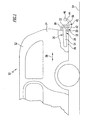
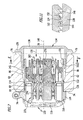
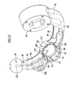
- FIG. 1 illustrated and designated as a whole by 10 motor vehicle comprises a motor vehicle body 12, which carries a bumper unit 16 at a rear portion 14. Covered by the bumper unit 16 Rear side 18 of the rear portion 14 and the bumper unit 16 is a cross member 22 of a coupling support unit 20 is provided which is fixed by side support 24 at the rear portion 14 of the vehicle body 12 characterized in that the side support 24 extend parallel to a longitudinal direction 26 of the vehicle body 12 and in lateral areas 28 of the rear portion 14 are fixed thereto.
- the coupling support unit 20 is further provided with a designated as a whole by 30 bearing unit whose bearing base 32 is fixedly connected to the cross member 22.
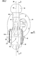
- the bearing assembly 30 further includes a bearing member, generally designated 34, which is connected to a first end 42 of a ball neck, generally designated 40, extending from the first end 42 to a second end 44 and a second end 44 thereof carries as a whole with 46 designated coupling ball.
- the bearing member 34 may be a bearing member fixedly connected to the bearing base 32 or detachably mountable to the bearing base 32.
- the bearing element 34 may be a pivot bearing element, which is pivotable about a pivot axis designated 36 relative to the bearing base 32, so that the ball neck 40 of the in Fig. 2 working position A shown by solid lines in a rest position R shown in dashed lines is pivotable, in which the ball neck 40 extends from the bearing base 32 transversely to the longitudinal direction 26 of the vehicle body 12 and thus along the cross member 22.
- the ball neck 40 runs in the rest position R shown in dashed lines transversely to a vertical longitudinal center plane 38 of the motor vehicle body 12 and also the coupling support unit 20, wherein the vertical longitudinal center plane 38 thus also runs parallel to the longitudinal direction 26.
- pivot axis 36 preferably extends transversely to the longitudinal center plane 38, but inclined relative to the vertical longitudinal center plane 38 by an angle, wherein the angle is less than 70 ° and more than 20 °.
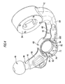
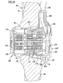
- FIG Fig. 3 An embodiment of such a ball neck 40 is enlarged in FIG Fig. 3 illustrated, wherein the ball neck 40 is integrally formed on the bearing element 34 and the bearing element 34 is formed in this case as a pivot bearing member for pivotable mounting to the bearing base 32.
- this carries at its second end 44 a ball stud 48 having a cylindrical to a central axis 50 extending lateral surface which extends at a radial distance about the central axis 50, which is smaller than a radius of the coupling ball 46th
- a housing receptacle 60 which is integrally integrated into the ball neck 40 and in the form of an annular body 62 which is located between a ball neck portion 64 which extends from the first end 42 of the ball neck 40 to the annular body 62 and a second ball neck portion 66, which extends from the annular body 62 to the second end 44 of the ball neck.
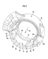
- the ring body 62 of the housing receptacle 60 encloses a receiving channel of the housing receptacle 60, designated as a whole by 72, which extends from a first end face 74 of the annular body 62 to a second end face 76 of the annular body 62 and forms a central axis 78 which runs transversely to the longitudinal center plane 38 , while it may be inclined relative to the longitudinal center plane 38 by an acute angle, but preferably but perpendicular to the longitudinal center plane 38 extends.
- the receiving channel 72 is formed by a channel inner wall 82 enclosing this, which has a substantially cylindrical to the central axis 78 extending and rotating around the central axis 78 wall portion 84 following the first end face 74 and extending from the wall portion 84 and up to the second end face 76 has conically widening wall region 86, which thus at the transition to the second end face 76 at a greater radial distance from the central axis 78 extends as close to the cylindrical wall portion 84th
- the receiving channel 72 is provided with positive locking elements 92, which are formed as widening radially relative to the conical wall portion 86 pockets 94 which extend from the cylindrical wall portion 84 in the direction of the second end face 76 and lying in the end face 76 pocket openings 96 , so that the pockets 94 are accessible via the pocket openings 96 lying in the second end face 76.
- a cable guide trough 102 running in the first ball neck section 64 opens into the conical wall region 86 and has an opening 104 which opens into the conical wall region 86 and adjoins the second end face 76.
- the cable guide channel 102 is set back both with respect to the second end face 76 and a surface 68 of the first ball neck section 64.
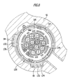
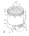
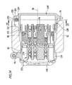
- socket receptacle 60 As in the Fig. 3 and 6 to 10 is shown, in the socket receptacle 60 as a whole with 110 designated outlet used, which has a designated as a whole with 112 socket housing, which engages in the socket receptacle 60.
- the socket housing 112 in turn comprises a housing sleeve 114, which is provided with an insertion opening 116.
- the insertion opening 116 can be closed by a cover 118, which is mounted on the housing sleeve 114 so as to be pivotable about a pivot axis 124 with a cover hinge designated as a whole by 122.
- the cover hinge 122 is integrally formed on a subsequent to the insertion opening 116 collar 126 which forms an engageable with the first end face 74 of the socket receptacle 60 bearing surface 128 with which the socket housing 112 in the mounted position against the socket receptacle 60 and against movement in Direction of the second end face 76 is fixed.
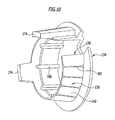
- the housing sleeve 114 extends from the insertion opening 116 to a rear opening 132, which can be opened by a housing cover 134.
- the housing cover 134 engages over the rear opening 132 with a cover body 136, to which a retaining ring 138 is integrally formed, which surrounds the housing sleeve 114 on an outer circumferential side 142.
- the housing sleeve 114 To connect the housing cover 134 with the housing sleeve 114, the housing sleeve 114 on its outer peripheral side 142 near the rear opening 132 latching teeth 144, which have parallel to a central axis 146 of the socket housing 112 a plurality of successive ratchet teeth 148.
- pairs of opposing locking teeth 144 with respect to the arrangement of their locking teeth 148 are identical, wherein the locking teeth 148 of different pairs in the direction of the central axis 146 may be offset from each other to allow in the direction of the central axis 146 an even finer positioning of the retaining ring 138 to the housing sleeve , as by the distance of the ratchet teeth 144th is given, namely the fact that the latching takes place in each case by at least a pair of opposing locking teeth 144, while another pair or other pairs do not contribute in this position for locking.
- locking teeth 148 engages, as in Fig. 11 shown, formed on the retaining ring 138 counter-teeth 152 a, which has at least one locking tooth 154, but may also have other locking teeth 154 may have.
- the locking teeth 144 and the counter teeth 152 are formed so that when pushing the retaining ring 138 in a Aufsetzcardi 156, which is parallel to the central axis 146, the two teeth 144 and 152 interlock and secure each other, preferably inseparable, lock.
- the placement of the housing cover 134 in the Aufsetzcardi 156 takes place until the retaining ring 138 rests against the socket receptacle 60, so that thereby the entire socket 110 is securely held against movement in the direction of the central axis 78 of the receiving channel 72 to the socket 60, on the one hand the contact surface 128 rests against the first end face 74 of the socket receptacle 60 and, on the other hand, the retaining ring 138 is supported on the socket receptacle 60.
- the support of the retaining ring 138 on the socket receptacle 60 can be effected by a radially over the retaining ring 138 protruding support flange 158 which can rest on the second end face 76 and the retaining ring 138 secures against movement in the direction of the first end face 74.
- the retaining ring 138 being provided with a conically extending outer surface 162, which faces the wall region 86 running conically with respect to the central axis 78, and in particular has the same cone angle as the conically extending wall portion 86, so that by placing the retaining ring 138 on the housing sleeve 114, a centering of the housing sleeve 114 due to the voltage applied to the conical wall portion 86 conical outer surface 162 and a support against movement of the retaining ring 138 in the direction the first end face 74 takes place.
- the outer surface 162 may be provided with outwardly projecting scraping ribs 163, which ensure an even better fit fit and contribute to tolerance compensation.
- a radial centering of the housing sleeve 114 also takes place through the cylindrical wall region 84 of the channel inner wall 82 in the region in a region adjoining the collar 126, so that a secure fixation of the socket housing 112 in the socket receptacle 60 takes place.
- the locking teeth 144 has a plurality of locking teeth 148 and the counter teeth 152 can thus be latched in one of the plurality of locking teeth 148 corresponding plurality of locking positions with the locking teeth 144, thus allowing, when placing the retaining ring 138 with the housing cover 134th and shifting the same in the direction of placement 156 to compensate dimensional tolerances in the region of the annular body 62, which arise in a production of the annular body 62 as a forged part.
- the positioning by the wedge body 174 can still be made more resistant to tolerances that the wedge body 174 are provided with outwardly projecting scratch ribs 175.
- housing sleeve 114 is provided in an end portion 182 carrying the locking teeth 144 with slots 184 running parallel to the central axis 146, in which webs 186 formed on the retaining ring 138 and projecting radially in the direction of the central axis 146 engage.
- the slots 184 are arranged around the central axis 146 at equal angular intervals and the corresponding webs 186 also arranged at equal angular intervals, so that the possibility exists, the housing sleeve 114 positively locked in different rotational positions relative to the retaining ring 138 rotatably and thereby different rotational positions of the housing sleeve 114 relative to the retaining ring 138 pretend.
- the second ball neck portion 66 and / or the coupling ball 46 a sensor system associated with 202, to which a sensor connecting line 204 is guided, passing through a ball neck portion 66, the ball stud 48 and optionally the coupling ball 46 passing through channel 206 which also opens into the receiving channel 72 of the socket receptacle 60, so that the sensor connection line 204 is to continue within the receiving channel 72.
- Such a sensor system 202 is for example a kink angle sensor for detecting a bending angle between the ball neck 40 and a towbar provided on a tow ball coupling and / or a sensor system for detecting acting on the coupling ball 46 and / or the ball neck 40 forces.
- a step-shaped recess 212 is provided, which extends from a relative to the channel inner wall 82 recessed opening portion 214 of the channel 206 in the receiving channel 72 up to the cable guide groove 102, in particular on a side facing away from the form-locking elements 92 side of the conical wall portion 86 extends.
- FIG. 14 and 15 shows the sensor connection line 204 to protect the same on the retaining ring 138 'guided in that in the region of the support flange 158, which faces the stepped recess 212, to the support flange 158 a parallel to the outer surface 162 of the retaining ring 138 extending support web 222 is arranged, the at a distance from the outer surface 162 of the retaining ring 138 ', so that between the support web 222 and the retaining ring 138', a U-shaped channel 224 is formed, in which the sensor connection line 204 inserted and through which the connecting line 204 is guided, so that against protected mechanical effects in the retaining ring 138 ', led from the mouth region 214 to the cable guide trough 102, run.
- connection line 204 coming from the sensor system 202 is introduced from the opening area 214 "into the housing cover 134" by the retaining ring 138 and secured by means of a plug connection 232 fixed to the housing cover 134 ", preferably the cover body 136 of the housing cover 134" in the wiring harness 108 connected to the power outlet 106 sensor line 234 connected so that the power outlet cable 106 comprehensive harness 108 can be equipped in advance with the sensor line 234, which then within the housing cover 134 "via the connector 232 with the coming from the sensor system 202 sensor connection line 204th can be connected.
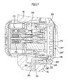
- FIG Fig. 17 In a fifth embodiment of a trailer coupling according to the invention, shown in FIG Fig. 17 , those parts which are identical to those of the preceding embodiment are provided with the same reference numerals, so that with respect to the description of the same reference may be made in full to the comments on the preceding embodiments, in particular the first embodiment.
- the housing cover 134 "'so formed that it is still provided with an electronic sensor system 202 associated circuit 242, for example, an evaluation circuit for the sensor system 202, wherein the circuit 242 preferably on an inside of the Cover body 136 '' in a receiving space 238 of the housing cover 134 '' is arranged and held.
- a connector housing 244 is formed in which plug contact units 246 are arranged, in which pins 248 of the sensor connection line 204 can be inserted, so that a connection between the sensor connection line 204 with the circuit 242 via a connector 252 produced is, from which the connector housing 244 and the plug-in contact units 246 in the housing cover 234 '' are integrated.
- the housing sleeve 114 "" itself provided with a cover 262, the cover 262, for example, with a holding portion 264 in the housing sleeve 114 "" engages and thereby either by positive engagement or by others Mounting options, such as bonding, with the housing sleeve 114 "" is connected.
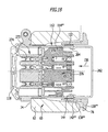
- FIG Fig. 19 is analogous to in Fig. 14 and 15 illustrated third embodiment of the retaining ring 138 ""'with the support web 222 ""', so that the channel 224 ""'forms, in which the sensor connection line 204 through the retaining ring 138 ""' out of the mouth portion 214 to the cable guide trough 102 can be.
- a contact carrier 272 is provided in the socket 110 within the socket housing 112, in which plug contacts 274 are provided which can be connected to a plug-in plug 110 in the socket.
- the plug contacts 274 are in turn contacted by a designated as a whole with 276 contact plug, which in turn has contact elements 278, which are connected on the one hand with the plug contacts 274 in the inserted state of the contact plug 276 and on the other hand connected to individual wires 282 of the socket supply line 106.
Landscapes
- Engineering & Computer Science (AREA)
- Transportation (AREA)
- Mechanical Engineering (AREA)
- Details Of Connecting Devices For Male And Female Coupling (AREA)
- Agricultural Machines (AREA)
Applications Claiming Priority (1)
| Application Number | Priority Date | Filing Date | Title |
|---|---|---|---|
| DE102014108071.8A DE102014108071A1 (de) | 2014-06-06 | 2014-06-06 | Anhängekupplung |
Publications (3)
| Publication Number | Publication Date |
|---|---|
| EP2952368A2 true EP2952368A2 (fr) | 2015-12-09 |
| EP2952368A3 EP2952368A3 (fr) | 2016-04-27 |
| EP2952368B1 EP2952368B1 (fr) | 2019-04-24 |
Family
ID=53365789
Family Applications (2)
| Application Number | Title | Priority Date | Filing Date |
|---|---|---|---|
| EP15169689.5A Active EP2952367B1 (fr) | 2014-06-06 | 2015-05-28 | Attelage |
| EP15169694.5A Active EP2952368B1 (fr) | 2014-06-06 | 2015-05-28 | Attelage |
Family Applications Before (1)
| Application Number | Title | Priority Date | Filing Date |
|---|---|---|---|
| EP15169689.5A Active EP2952367B1 (fr) | 2014-06-06 | 2015-05-28 | Attelage |
Country Status (3)
| Country | Link |
|---|---|
| US (1) | US9744822B2 (fr) |
| EP (2) | EP2952367B1 (fr) |
| DE (1) | DE102014108071A1 (fr) |
Cited By (4)
| Publication number | Priority date | Publication date | Assignee | Title |
|---|---|---|---|---|
| EP3456554A1 (fr) * | 2017-09-14 | 2019-03-20 | ACPS Automotive GmbH | Attelage de remorque |
| EP3819138A1 (fr) | 2019-11-11 | 2021-05-12 | ACPS Automotive GmbH | Unité d'installation |
| EP3456555B1 (fr) | 2017-09-14 | 2021-05-26 | ACPS Automotive GmbH | Attelage de remorque |
| US20210370731A1 (en) * | 2020-05-27 | 2021-12-02 | ACPS Automotive GmbH | Trailer device |
Families Citing this family (10)
| Publication number | Priority date | Publication date | Assignee | Title |
|---|---|---|---|---|
| DE102014118879A1 (de) * | 2014-12-17 | 2016-06-23 | Scambia Holdings Cyprus Limited | Anhängekupplung |
| DE102015112741A1 (de) † | 2015-08-03 | 2017-02-09 | Scambia Holdings Cyprus Limited | Anhängekupplung |
| DE102016110460A1 (de) * | 2016-03-23 | 2017-09-28 | Westfalia-Automotive Gmbh | Tragelement mit einem Sensor |
| DE102016119393A1 (de) * | 2016-10-07 | 2018-04-12 | Westfalia-Automotive Gmbh | Anhängekupplung mit einer Anschlussvorrichtung |
| DE102017102504A1 (de) * | 2017-02-08 | 2018-08-09 | Bosal Acps Holding 2 B.V. | Anhängekupplung |
| DE102017109488A1 (de) * | 2017-05-03 | 2018-11-08 | ACPS Automotive GmbH | An einem Heckbereich eines Kraftfahrzeugs montierbare Halteeinrichtung |
| EP3806248A1 (fr) * | 2019-10-08 | 2021-04-14 | Plastimat GmbH | Prise électrique destinée au raccordement électrique d'une remorque à un véhicule automobile |
| DE102020125607A1 (de) | 2020-09-30 | 2022-03-31 | ACPS Automotive GmbH | Einbaueinheit |
| DE102020128532A1 (de) * | 2020-10-29 | 2022-05-05 | ACPS Automotive GmbH | Einbaueinheit |
| DE102022106033A1 (de) * | 2022-03-15 | 2023-09-21 | Westfalia-Automotive Gmbh | Betriebsgerät zum Betreiben einer Anhängekupplung |
Family Cites Families (15)
| Publication number | Priority date | Publication date | Assignee | Title |
|---|---|---|---|---|
| DE29825216U1 (de) * | 1997-04-14 | 2006-04-27 | Oris Fahrzeugteile Hans Riehle Gmbh | Kontakteinheit und Anhängekupplung für Kraftfahrzeuge mit einer Kontakteinheit |
| DE19715469C2 (de) * | 1997-04-14 | 1999-11-18 | Oris Fahrzeugteile Riehle H | Anhängekupplung für Kraftfahrzeuge |
| DE29800542U1 (de) * | 1998-01-07 | 1998-03-26 | Jaeger Erich Gmbh & Co Kg | Steckdose für mehrpolige Steckvorrichtungen |
| DE29807409U1 (de) * | 1998-01-07 | 1998-06-25 | Jaeger Erich Gmbh & Co Kg | Steckdose für mehrpolige Steckvorrichtungen |
| EP1006624A3 (fr) * | 1998-12-01 | 2002-06-05 | ERICH JAEGER GmbH & Co. KG | Prise pour connexions électriques |
| DE10144254A1 (de) * | 2001-09-03 | 2003-04-03 | Oris Fahrzeugteile Riehle H | Anhängekupplung |
| DE20204423U1 (de) * | 2002-03-20 | 2002-07-04 | Jaeger Erich Gmbh & Co Kg | Steckdose für elektrische Steckverbindungen |
| DE102006035261A1 (de) * | 2006-07-29 | 2008-01-31 | Scambia Industrial Developments Aktiengesellschaft | Anhängekupplung |
| DE202007013022U1 (de) * | 2007-09-17 | 2007-11-15 | Plastimat Gmbh | Steckdose für eine mehrpolige Steckvorrichtung |
| DE202009005591U1 (de) * | 2009-04-14 | 2009-06-18 | Plastimat Gmbh | Steckdose für eine mehrpolige Steckvorrichtung |
| DE102009046180A1 (de) * | 2009-10-29 | 2011-05-05 | Scambia Industrial Developments Aktiengesellschaft | Anhängekupplung |
| DE202010004439U1 (de) * | 2010-03-29 | 2011-08-11 | Scambia Industrial Developments Aktiengesellschaft | Betätigungseinrichtung |
| DE102010029414A1 (de) * | 2010-05-27 | 2011-12-01 | Scambia Industrial Developments Aktiengesellschaft | Anhängekupplung |
| DE102010049614A1 (de) * | 2010-10-26 | 2012-04-26 | Westfalia-Automotive Gmbh | Anhängekupplung mit einem Sensor |
| DE102011053506A1 (de) * | 2011-09-12 | 2013-03-14 | Scambia Holdings Cyprus Ltd. | Anhängekupplung |
-
2014
- 2014-06-06 DE DE102014108071.8A patent/DE102014108071A1/de not_active Ceased
-
2015
- 2015-05-28 EP EP15169689.5A patent/EP2952367B1/fr active Active
- 2015-05-28 EP EP15169694.5A patent/EP2952368B1/fr active Active
- 2015-06-05 US US14/731,975 patent/US9744822B2/en active Active
Non-Patent Citations (1)
| Title |
|---|
| None |
Cited By (8)
| Publication number | Priority date | Publication date | Assignee | Title |
|---|---|---|---|---|
| EP3456554A1 (fr) * | 2017-09-14 | 2019-03-20 | ACPS Automotive GmbH | Attelage de remorque |
| EP3456554B1 (fr) | 2017-09-14 | 2021-03-10 | ACPS Automotive GmbH | Attelage de remorque |
| EP3456555B1 (fr) | 2017-09-14 | 2021-05-26 | ACPS Automotive GmbH | Attelage de remorque |
| EP3819138A1 (fr) | 2019-11-11 | 2021-05-12 | ACPS Automotive GmbH | Unité d'installation |
| DE102019130312A1 (de) * | 2019-11-11 | 2021-05-12 | ACPS Automotive GmbH | Einbaueinheit |
| US11577563B2 (en) | 2019-11-11 | 2023-02-14 | ACPS Automotive GmbH | Installation unit with latching elements for carrier unit mounted on a motor vehicle |
| US20210370731A1 (en) * | 2020-05-27 | 2021-12-02 | ACPS Automotive GmbH | Trailer device |
| US11707954B2 (en) * | 2020-05-27 | 2023-07-25 | ACPS Automotive GmbH | Trailer device |
Also Published As
| Publication number | Publication date |
|---|---|
| US20150352915A1 (en) | 2015-12-10 |
| US9744822B2 (en) | 2017-08-29 |
| EP2952367A1 (fr) | 2015-12-09 |
| EP2952368B1 (fr) | 2019-04-24 |
| DE102014108071A1 (de) | 2015-12-17 |
| EP2952367B1 (fr) | 2020-01-01 |
| EP2952368A3 (fr) | 2016-04-27 |
Similar Documents
| Publication | Publication Date | Title |
|---|---|---|
| EP2952368B1 (fr) | Attelage | |
| EP2367235B1 (fr) | Prise destinée à la liaison avec une douille | |
| DE4433704C2 (de) | Steckbuchse | |
| DE102007038693B4 (de) | Verbindungsvorrichtung für einen Steckverbinder | |
| LU93308B1 (de) | Steckverbinderteil, insbesondere zum Übertragen eines Ladestroms zum Aufladen eines Elektrofahrzeugs | |
| EP3374234B1 (fr) | Système de fixation | |
| DE102016121847B4 (de) | Steckverbinderteil und Verfahren zum Montieren eines Steckverbinderteils | |
| EP1257448B1 (fr) | Dispositif de rechauffement d'un liquide dans un systeme de conduite | |
| EP3456555A1 (fr) | Attelage de remorque | |
| EP2913208B1 (fr) | Attelage doté d'une unité de contact de véhicule | |
| DE102006053477C5 (de) | Steckdose | |
| EP3127725B2 (fr) | Attelage | |
| EP1587175B1 (fr) | Connecteur pour cable transmettant des signaux | |
| EP2208646B1 (fr) | Boîtier de raccordement destiné à être installé dans une carrosserie de véhicule | |
| DE4301506A1 (de) | Steckdose für eine Steckverbindung für den elektrischen Anschluß von Kraftfahrzeuganhängern an Kraftfahrzeugen | |
| EP2829422B1 (fr) | Système d'attelage pour véhicules automobiles | |
| EP2538507B1 (fr) | Adaptateur de barre collectrice | |
| DE102017204908A1 (de) | Sensorachslagereinheit zum Lagern einer Zugachse | |
| WO1990010323A1 (fr) | Passe-cable a connecteur electrique a fiche | |
| DE202010018012U1 (de) | Befestigungsanordnung für Kabelführungen | |
| DE202005011694U1 (de) | Stecker für eine elektrische Steckverbindung | |
| EP3456553B1 (fr) | Attelage de remorque | |
| DE29825216U1 (de) | Kontakteinheit und Anhängekupplung für Kraftfahrzeuge mit einer Kontakteinheit | |
| EP2428403A2 (fr) | Couplage pour un système de support de charge doté d'une unité de contact | |
| DE102009050932A1 (de) | Anhängerkupplungseinrichtung für einen Kraftwagen |
Legal Events
| Date | Code | Title | Description |
|---|---|---|---|
| PUAI | Public reference made under article 153(3) epc to a published international application that has entered the european phase |
Free format text: ORIGINAL CODE: 0009012 |
|
| AK | Designated contracting states |
Kind code of ref document: A2 Designated state(s): AL AT BE BG CH CY CZ DE DK EE ES FI FR GB GR HR HU IE IS IT LI LT LU LV MC MK MT NL NO PL PT RO RS SE SI SK SM TR |
|
| AX | Request for extension of the european patent |
Extension state: BA ME |
|
| PUAL | Search report despatched |
Free format text: ORIGINAL CODE: 0009013 |
|
| AK | Designated contracting states |
Kind code of ref document: A3 Designated state(s): AL AT BE BG CH CY CZ DE DK EE ES FI FR GB GR HR HU IE IS IT LI LT LU LV MC MK MT NL NO PL PT RO RS SE SI SK SM TR |
|
| AX | Request for extension of the european patent |
Extension state: BA ME |
|
| RIC1 | Information provided on ipc code assigned before grant |
Ipc: B60D 1/06 20060101AFI20160323BHEP Ipc: B60D 1/54 20060101ALI20160323BHEP Ipc: B60D 1/48 20060101ALI20160323BHEP Ipc: B60D 1/64 20060101ALI20160323BHEP Ipc: B60D 1/56 20060101ALI20160323BHEP Ipc: H01R 33/945 20060101ALI20160323BHEP |
|
| 17P | Request for examination filed |
Effective date: 20160915 |
|
| RBV | Designated contracting states (corrected) |
Designated state(s): AL AT BE BG CH CY CZ DE DK EE ES FI FR GB GR HR HU IE IS IT LI LT LU LV MC MK MT NL NO PL PT RO RS SE SI SK SM TR |
|
| RAP1 | Party data changed (applicant data changed or rights of an application transferred) |
Owner name: BOSAL ACPS HOLDING 2 B.V. |
|
| GRAP | Despatch of communication of intention to grant a patent |
Free format text: ORIGINAL CODE: EPIDOSNIGR1 |
|
| STAA | Information on the status of an ep patent application or granted ep patent |
Free format text: STATUS: GRANT OF PATENT IS INTENDED |
|
| INTG | Intention to grant announced |
Effective date: 20181116 |
|
| GRAS | Grant fee paid |
Free format text: ORIGINAL CODE: EPIDOSNIGR3 |
|
| GRAA | (expected) grant |
Free format text: ORIGINAL CODE: 0009210 |
|
| STAA | Information on the status of an ep patent application or granted ep patent |
Free format text: STATUS: THE PATENT HAS BEEN GRANTED |
|
| AK | Designated contracting states |
Kind code of ref document: B1 Designated state(s): AL AT BE BG CH CY CZ DE DK EE ES FI FR GB GR HR HU IE IS IT LI LT LU LV MC MK MT NL NO PL PT RO RS SE SI SK SM TR |
|
| REG | Reference to a national code |
Ref country code: GB Ref legal event code: FG4D Free format text: NOT ENGLISH |
|
| REG | Reference to a national code |
Ref country code: CH Ref legal event code: EP |
|
| REG | Reference to a national code |
Ref country code: AT Ref legal event code: REF Ref document number: 1123705 Country of ref document: AT Kind code of ref document: T Effective date: 20190515 Ref country code: IE Ref legal event code: FG4D Free format text: LANGUAGE OF EP DOCUMENT: GERMAN |
|
| REG | Reference to a national code |
Ref country code: DE Ref legal event code: R096 Ref document number: 502015008775 Country of ref document: DE |
|
| REG | Reference to a national code |
Ref country code: NL Ref legal event code: MP Effective date: 20190424 |
|
| REG | Reference to a national code |
Ref country code: LT Ref legal event code: MG4D |
|
| PG25 | Lapsed in a contracting state [announced via postgrant information from national office to epo] |
Ref country code: NL Free format text: LAPSE BECAUSE OF FAILURE TO SUBMIT A TRANSLATION OF THE DESCRIPTION OR TO PAY THE FEE WITHIN THE PRESCRIBED TIME-LIMIT Effective date: 20190424 |
|
| RAP2 | Party data changed (patent owner data changed or rights of a patent transferred) |
Owner name: ACPS AUTOMOTIVE GMBH |
|
| PG25 | Lapsed in a contracting state [announced via postgrant information from national office to epo] |
Ref country code: ES Free format text: LAPSE BECAUSE OF FAILURE TO SUBMIT A TRANSLATION OF THE DESCRIPTION OR TO PAY THE FEE WITHIN THE PRESCRIBED TIME-LIMIT Effective date: 20190424 Ref country code: HR Free format text: LAPSE BECAUSE OF FAILURE TO SUBMIT A TRANSLATION OF THE DESCRIPTION OR TO PAY THE FEE WITHIN THE PRESCRIBED TIME-LIMIT Effective date: 20190424 Ref country code: FI Free format text: LAPSE BECAUSE OF FAILURE TO SUBMIT A TRANSLATION OF THE DESCRIPTION OR TO PAY THE FEE WITHIN THE PRESCRIBED TIME-LIMIT Effective date: 20190424 Ref country code: LT Free format text: LAPSE BECAUSE OF FAILURE TO SUBMIT A TRANSLATION OF THE DESCRIPTION OR TO PAY THE FEE WITHIN THE PRESCRIBED TIME-LIMIT Effective date: 20190424 Ref country code: NO Free format text: LAPSE BECAUSE OF FAILURE TO SUBMIT A TRANSLATION OF THE DESCRIPTION OR TO PAY THE FEE WITHIN THE PRESCRIBED TIME-LIMIT Effective date: 20190724 Ref country code: PT Free format text: LAPSE BECAUSE OF FAILURE TO SUBMIT A TRANSLATION OF THE DESCRIPTION OR TO PAY THE FEE WITHIN THE PRESCRIBED TIME-LIMIT Effective date: 20190824 Ref country code: SE Free format text: LAPSE BECAUSE OF FAILURE TO SUBMIT A TRANSLATION OF THE DESCRIPTION OR TO PAY THE FEE WITHIN THE PRESCRIBED TIME-LIMIT Effective date: 20190424 Ref country code: AL Free format text: LAPSE BECAUSE OF FAILURE TO SUBMIT A TRANSLATION OF THE DESCRIPTION OR TO PAY THE FEE WITHIN THE PRESCRIBED TIME-LIMIT Effective date: 20190424 |
|
| PG25 | Lapsed in a contracting state [announced via postgrant information from national office to epo] |
Ref country code: LV Free format text: LAPSE BECAUSE OF FAILURE TO SUBMIT A TRANSLATION OF THE DESCRIPTION OR TO PAY THE FEE WITHIN THE PRESCRIBED TIME-LIMIT Effective date: 20190424 Ref country code: PL Free format text: LAPSE BECAUSE OF FAILURE TO SUBMIT A TRANSLATION OF THE DESCRIPTION OR TO PAY THE FEE WITHIN THE PRESCRIBED TIME-LIMIT Effective date: 20190424 Ref country code: BG Free format text: LAPSE BECAUSE OF FAILURE TO SUBMIT A TRANSLATION OF THE DESCRIPTION OR TO PAY THE FEE WITHIN THE PRESCRIBED TIME-LIMIT Effective date: 20190724 Ref country code: GR Free format text: LAPSE BECAUSE OF FAILURE TO SUBMIT A TRANSLATION OF THE DESCRIPTION OR TO PAY THE FEE WITHIN THE PRESCRIBED TIME-LIMIT Effective date: 20190725 Ref country code: RS Free format text: LAPSE BECAUSE OF FAILURE TO SUBMIT A TRANSLATION OF THE DESCRIPTION OR TO PAY THE FEE WITHIN THE PRESCRIBED TIME-LIMIT Effective date: 20190424 |
|
| REG | Reference to a national code |
Ref country code: CH Ref legal event code: PL |
|
| PG25 | Lapsed in a contracting state [announced via postgrant information from national office to epo] |
Ref country code: IS Free format text: LAPSE BECAUSE OF FAILURE TO SUBMIT A TRANSLATION OF THE DESCRIPTION OR TO PAY THE FEE WITHIN THE PRESCRIBED TIME-LIMIT Effective date: 20190824 |
|
| REG | Reference to a national code |
Ref country code: DE Ref legal event code: R097 Ref document number: 502015008775 Country of ref document: DE |
|
| PG25 | Lapsed in a contracting state [announced via postgrant information from national office to epo] |
Ref country code: CH Free format text: LAPSE BECAUSE OF NON-PAYMENT OF DUE FEES Effective date: 20190531 Ref country code: MC Free format text: LAPSE BECAUSE OF FAILURE TO SUBMIT A TRANSLATION OF THE DESCRIPTION OR TO PAY THE FEE WITHIN THE PRESCRIBED TIME-LIMIT Effective date: 20190424 Ref country code: RO Free format text: LAPSE BECAUSE OF FAILURE TO SUBMIT A TRANSLATION OF THE DESCRIPTION OR TO PAY THE FEE WITHIN THE PRESCRIBED TIME-LIMIT Effective date: 20190424 Ref country code: LI Free format text: LAPSE BECAUSE OF NON-PAYMENT OF DUE FEES Effective date: 20190531 Ref country code: CZ Free format text: LAPSE BECAUSE OF FAILURE TO SUBMIT A TRANSLATION OF THE DESCRIPTION OR TO PAY THE FEE WITHIN THE PRESCRIBED TIME-LIMIT Effective date: 20190424 Ref country code: EE Free format text: LAPSE BECAUSE OF FAILURE TO SUBMIT A TRANSLATION OF THE DESCRIPTION OR TO PAY THE FEE WITHIN THE PRESCRIBED TIME-LIMIT Effective date: 20190424 Ref country code: SK Free format text: LAPSE BECAUSE OF FAILURE TO SUBMIT A TRANSLATION OF THE DESCRIPTION OR TO PAY THE FEE WITHIN THE PRESCRIBED TIME-LIMIT Effective date: 20190424 Ref country code: DK Free format text: LAPSE BECAUSE OF FAILURE TO SUBMIT A TRANSLATION OF THE DESCRIPTION OR TO PAY THE FEE WITHIN THE PRESCRIBED TIME-LIMIT Effective date: 20190424 |
|
| REG | Reference to a national code |
Ref country code: BE Ref legal event code: MM Effective date: 20190531 |
|
| PG25 | Lapsed in a contracting state [announced via postgrant information from national office to epo] |
Ref country code: IT Free format text: LAPSE BECAUSE OF FAILURE TO SUBMIT A TRANSLATION OF THE DESCRIPTION OR TO PAY THE FEE WITHIN THE PRESCRIBED TIME-LIMIT Effective date: 20190424 Ref country code: SM Free format text: LAPSE BECAUSE OF FAILURE TO SUBMIT A TRANSLATION OF THE DESCRIPTION OR TO PAY THE FEE WITHIN THE PRESCRIBED TIME-LIMIT Effective date: 20190424 Ref country code: LU Free format text: LAPSE BECAUSE OF NON-PAYMENT OF DUE FEES Effective date: 20190528 |
|
| PLBE | No opposition filed within time limit |
Free format text: ORIGINAL CODE: 0009261 |
|
| STAA | Information on the status of an ep patent application or granted ep patent |
Free format text: STATUS: NO OPPOSITION FILED WITHIN TIME LIMIT |
|
| PG25 | Lapsed in a contracting state [announced via postgrant information from national office to epo] |
Ref country code: TR Free format text: LAPSE BECAUSE OF FAILURE TO SUBMIT A TRANSLATION OF THE DESCRIPTION OR TO PAY THE FEE WITHIN THE PRESCRIBED TIME-LIMIT Effective date: 20190424 |
|
| 26N | No opposition filed |
Effective date: 20200127 |
|
| PG25 | Lapsed in a contracting state [announced via postgrant information from national office to epo] |
Ref country code: IE Free format text: LAPSE BECAUSE OF NON-PAYMENT OF DUE FEES Effective date: 20190528 |
|
| PG25 | Lapsed in a contracting state [announced via postgrant information from national office to epo] |
Ref country code: SI Free format text: LAPSE BECAUSE OF FAILURE TO SUBMIT A TRANSLATION OF THE DESCRIPTION OR TO PAY THE FEE WITHIN THE PRESCRIBED TIME-LIMIT Effective date: 20190424 Ref country code: BE Free format text: LAPSE BECAUSE OF NON-PAYMENT OF DUE FEES Effective date: 20190531 |
|
| REG | Reference to a national code |
Ref country code: DE Ref legal event code: R082 Ref document number: 502015008775 Country of ref document: DE Representative=s name: HOEGER, STELLRECHT & PARTNER PATENTANWAELTE MB, DE Ref country code: DE Ref legal event code: R081 Ref document number: 502015008775 Country of ref document: DE Owner name: ACPS AUTOMOTIVE GMBH, DE Free format text: FORMER OWNER: BOSAL ACPS HOLDING 2 B.V., VIANEN, NL |
|
| PG25 | Lapsed in a contracting state [announced via postgrant information from national office to epo] |
Ref country code: CY Free format text: LAPSE BECAUSE OF FAILURE TO SUBMIT A TRANSLATION OF THE DESCRIPTION OR TO PAY THE FEE WITHIN THE PRESCRIBED TIME-LIMIT Effective date: 20190424 |
|
| REG | Reference to a national code |
Ref country code: AT Ref legal event code: MM01 Ref document number: 1123705 Country of ref document: AT Kind code of ref document: T Effective date: 20200528 |
|
| PG25 | Lapsed in a contracting state [announced via postgrant information from national office to epo] |
Ref country code: HU Free format text: LAPSE BECAUSE OF FAILURE TO SUBMIT A TRANSLATION OF THE DESCRIPTION OR TO PAY THE FEE WITHIN THE PRESCRIBED TIME-LIMIT; INVALID AB INITIO Effective date: 20150528 Ref country code: MT Free format text: LAPSE BECAUSE OF FAILURE TO SUBMIT A TRANSLATION OF THE DESCRIPTION OR TO PAY THE FEE WITHIN THE PRESCRIBED TIME-LIMIT Effective date: 20190424 |
|
| PG25 | Lapsed in a contracting state [announced via postgrant information from national office to epo] |
Ref country code: AT Free format text: LAPSE BECAUSE OF NON-PAYMENT OF DUE FEES Effective date: 20200528 |
|
| REG | Reference to a national code |
Ref country code: GB Ref legal event code: 732E Free format text: REGISTERED BETWEEN 20220224 AND 20220302 |
|
| PG25 | Lapsed in a contracting state [announced via postgrant information from national office to epo] |
Ref country code: MK Free format text: LAPSE BECAUSE OF FAILURE TO SUBMIT A TRANSLATION OF THE DESCRIPTION OR TO PAY THE FEE WITHIN THE PRESCRIBED TIME-LIMIT Effective date: 20190424 |
|
| REG | Reference to a national code |
Ref country code: DE Ref legal event code: R081 Ref document number: 502015008775 Country of ref document: DE Owner name: ACPS AUTOMOTIVE GMBH, DE Free format text: FORMER OWNER: ACPS AUTOMOTIVE GMBH, 71706 MARKGROENINGEN, DE |
|
| P01 | Opt-out of the competence of the unified patent court (upc) registered |
Effective date: 20230517 |
|
| PGFP | Annual fee paid to national office [announced via postgrant information from national office to epo] |
Ref country code: FR Payment date: 20230526 Year of fee payment: 9 Ref country code: DE Payment date: 20230519 Year of fee payment: 9 |
|
| PGFP | Annual fee paid to national office [announced via postgrant information from national office to epo] |
Ref country code: GB Payment date: 20230524 Year of fee payment: 9 |