EP2952064B1 - Automatische gruppierung über licht und ton - Google Patents
Automatische gruppierung über licht und ton Download PDFInfo
- Publication number
- EP2952064B1 EP2952064B1 EP14705216.1A EP14705216A EP2952064B1 EP 2952064 B1 EP2952064 B1 EP 2952064B1 EP 14705216 A EP14705216 A EP 14705216A EP 2952064 B1 EP2952064 B1 EP 2952064B1
- Authority
- EP
- European Patent Office
- Prior art keywords
- light
- light source
- signal
- received
- sound
- Prior art date
- Legal status (The legal status is an assumption and is not a legal conclusion. Google has not performed a legal analysis and makes no representation as to the accuracy of the status listed.)
- Active
Links
Images


Classifications
-
- H—ELECTRICITY
- H05—ELECTRIC TECHNIQUES NOT OTHERWISE PROVIDED FOR
- H05B—ELECTRIC HEATING; ELECTRIC LIGHT SOURCES NOT OTHERWISE PROVIDED FOR; CIRCUIT ARRANGEMENTS FOR ELECTRIC LIGHT SOURCES, IN GENERAL
- H05B47/00—Circuit arrangements for operating light sources in general, i.e. where the type of light source is not relevant
- H05B47/10—Controlling the light source
- H05B47/105—Controlling the light source in response to determined parameters
- H05B47/115—Controlling the light source in response to determined parameters by determining the presence or movement of objects or living beings
- H05B47/12—Controlling the light source in response to determined parameters by determining the presence or movement of objects or living beings by detecting audible sound
-
- H—ELECTRICITY
- H05—ELECTRIC TECHNIQUES NOT OTHERWISE PROVIDED FOR
- H05B—ELECTRIC HEATING; ELECTRIC LIGHT SOURCES NOT OTHERWISE PROVIDED FOR; CIRCUIT ARRANGEMENTS FOR ELECTRIC LIGHT SOURCES, IN GENERAL
- H05B47/00—Circuit arrangements for operating light sources in general, i.e. where the type of light source is not relevant
- H05B47/10—Controlling the light source
- H05B47/175—Controlling the light source by remote control
- H05B47/198—Grouping of control procedures or address assignation to light sources
- H05B47/199—Commissioning of light sources
-
- H—ELECTRICITY
- H05—ELECTRIC TECHNIQUES NOT OTHERWISE PROVIDED FOR
- H05B—ELECTRIC HEATING; ELECTRIC LIGHT SOURCES NOT OTHERWISE PROVIDED FOR; CIRCUIT ARRANGEMENTS FOR ELECTRIC LIGHT SOURCES, IN GENERAL
- H05B47/00—Circuit arrangements for operating light sources in general, i.e. where the type of light source is not relevant
- H05B47/10—Controlling the light source
- H05B47/175—Controlling the light source by remote control
- H05B47/196—Controlling the light source by remote control characterised by user interface arrangements
Definitions
- Embodiments of the present invention relate generally to the field of illumination systems, and, more specifically, to systems and methods for automatic grouping of multiple light sources within such illumination systems.
- Commissioning is a key activity in the deployment of current lighting systems.
- commissioning refers to the process of configuring a lighting system that takes place after the components of the system, such as e.g. light sources, sensors and wall switches, are installed in a structure and connected to power and, if necessary, to a data network.
- light sources that are to be controlled together are grouped and assigned to appropriate sensors and wall switches.
- a lighting group is identified as all the light sources, and possibly also the associated sensors and switches, within a room. Often times, this grouping and assignment is done manually, e.g. by a commissioning technician.
- the US 2007/160373 A1 discloses a method and system of distributed illumination and sensing, the system including devices, each device including an emitter to emit at least one of light and sound, a sensor to receive an indirect emission, and a controller to determine the existence and/or relative location of at least one of the other devices in response to the indirect emission.
- One object of the invention is to provide a system and method that allow automatic grouping of light sources in a room or a sub-section of a room.
- the proposed method is applicable to illumination systems comprising at least a first light source and a second light source and comprises the steps of the first light source emitting a first light signal and a first sound signal, using an intensity of the first light signal as received by a second light source and an intensity of the first sound signal as received by the second light source to determine a value of a grouping function, and assigning the first light source and the second light source to the same group of light sources when the determined value of the grouping function satisfies one or more pre-determined conditions.
- the term "light signal” refers to an optical wave of any frequency, such as e.g. visible light, infrared (IR), or ultraviolet, even though in practice visible or IR light is envisioned to be the most used.
- the term “sound signal” refers to an acoustic wave of any frequency, even though in practice ultrasound is envisioned to be the most used.
- grouping function in the present context is used to describe any function that takes as inputs at least the intensities of the light and the sound signals emitted by the first light source as measured by the second light source (further inputs are possible) and produces as an output one or more numeric values which may be evaluated against certain pre-determined conditions providing an indication whether or not the first and second light sources should be assigned to the same group.
- Embodiments of the present invention are based on several realizations. First of all, they are based on the realization that sound can be used for grouping of light sources. Because sound signals are attenuated by glass, the problem of a glass wall described in the background section of the present application could be overcome with sound-based grouping. Embodiments of the present invention are further based on recognition that grouping based on the use of sound alone would be prone to other problems. For example, in situations where the rooms are separated by mobile office partitions that do not extend all the way up to the ceiling, as if e.g. done in so-called "cubicle" office spaces, sound would be attenuated significantly less, leading to problems with correct grouping of light sources.
- Embodiments described herein advantageously utilize both light and sound measurements in order to group light sources, where the positive aspects of both solutions are exploited and used to complement one another. Comparing the intensities of the light and sound signals emitted by a first light source to one another, as detected by a second light source, by a way of using an appropriate function, referred to herein as a "grouping function", allows assessing whether the first and second light sources are physically located within the same room as well as making conclusions regarding the proximity of the first and second light sources. Consequently, a determination could be made whether or not the first and second light sources should be assigned to the same group in a manner that yields improved results over the prior art solutions.
- An additional advantage of such a solution is that it would require very little investment in upgrading the light sources in use now days because such light sources are already typically equipped not only with light receivers and transmitters but also with sound receivers and transmitters used for sunlight integration and presence detection.
- the grouping function may be dependent on a ratio between the intensity of the first light signal as received by the second light source and the intensity of the first sound signal as received by the second light source, or a derivative thereof, and the pre-determined condition for grouping could then comprise that the determined ratio is within a pre-determined range.
- the grouping function may be dependent on a difference between the intensity of the first light signal as received by the second light source and the intensity of the first sound signal as received by the second light source, or a derivative thereof.
- the method may further comprise obtaining an intensity of the first light signal as emitted by the first light source and an intensity of the first sound signal as emitted by the first sound source, determining a path loss of the first light signal as the difference between the intensity of the first light signal as emitted by the first light source and the intensity of the first light signal as received by the second light source, determining a path loss of the first sound signal as the difference between the intensity of the first sound signal as emitted by the first sound source and the intensity of the first sound signal as received by the second light source, and determining the value of the grouping function as the difference between the path loss of the first light signal and the path loss of the first sound signal, wherein the one or more predetermined conditions comprises the difference between the path loss of the first light signal and the path loss of the first sound signal being
- the method further includes the step of determining a difference between the time when the first light signal is received by the second light source and the time when the first sound signal is received by the second light source.
- a difference between the time of receipt of one signal and the time of receipt of another signal is sometimes referred to as a "time of flight” (TOF).
- TOF refers to the time delay between receipt of a light signal emitted by one light source and a sound signal emitted by the same light source.
- This embodiment is based on the recognition that the specific combination of light and sound measurements, as opposed to a combination of any other communication means, can obtain very accurate measurements of the TOF because due to the vastly different speeds of light and sound it is possible to accurately measure the time delay of the sound signal in comparison with the light signal.
- the device processing the measured time difference needs to have knowledge of the time difference in when the light and sound signals were emitted by the emitting light source.
- the processing device could be provided with information that the light sources are configured to emit the light and sound signals simultaneously or with a certain pre-determined delay between the emission of the light signal and the emission of the sound signal. Once that is known, the TOF allows making various conclusions based on how long it takes a signal to travel a certain distance through a medium.
- the first light source and the second light source may be assigned to the same group of light sources not only when the ratio between the received intensities of the light and sound signals is within the pre-determined range, but also when the determined difference between the time when the light signal is received and the time when the associated sound signal is received is below a pre-determined value.
- Such an embodiment allows using the TOF of the first sound signal, measured against the first light signal, as a further criterion for assigning the first and second light sources to the same group. In this manner, it is possible to differentiate between a group of light sources clustered in one area of a single room and a group of light sources in another area of the same room. This embodiment may be particular beneficial for large rooms, such as e.g.
- first and second light sources would be assigned to the same group when the distance between them is relatively small (e.g. both light sources are in the front of the auditorium), but would not be assigned to the same group when the distance between them is relatively large (e.g. one light source is in the front of the auditorium while the other one is in the back of the auditorium).
- the TOF may be used to normalize the detected intensity values. Namely, the intensity of the first light signal as received by the second light source and the intensity of the first sound signal as received by the second light source may be normalized to the determined difference between the time when the first light signal is received and the time when the associated sound signal is received, e.g. prior to determining the ratio between the intensities or prior to comparing the received intensities to some threshold values in order to make the grouping decision.
- This embodiment allows taking proper account of the possible different rates of decrease in the strengths of light and sound signals as a function of the distance travelled by the signals.
- the intensity of the first light signal as received by the second light source could be normalized to an intensity of the first light signal as emitted by the first light source and the intensity of the first sound signal as received by the second light source could be normalized to an intensity of the first sound signal as emitted by the first light source, e.g. prior to determining the ratio.
- This embodiment provides a manner alternative to that of using TOF for taking proper account of the possible different rates of decrease in the strengths of light and sound signals as a function of the distance travelled by the signals.
- the intensities of the first light and sound signals as emitted by the first light source may be pre-programmed (i.e., known ahead of time) to the device carrying out the present methods.
- the emitting intensities may be encoded into one or both of the first light and sound signals in any of the manners known in the art.
- the emitting intensities of both first light and sound signals may be encoded into the first light signal using a so-called coded light (CL) technique.
- CL coded light
- the first light source and the second light source may be assigned to the same group of light sources based on additional information.
- additional information e.g. to location of windows or projectors in a room, or any other information that may be useful in making the decision on whether or not the first and second light sources should be assigned to the same group.
- additional information may either be provided to the device carrying out the present methods as a part of the commissioning/grouping procedure or pre-stored in the device.
- the method may further comprise establishing that the first light source and the second light source should not be assigned to the same group of light sources when the intensity of the first light signal as received by the second light source is below a predetermined light intensity value and/or when the intensity of the first sound signal as received by the second light source is below a predetermined sound intensity value.
- the method may further comprise obtaining an intensity of the first light signal as received by a third light source and an intensity of the first sound signal as received by the third light source to determine a further value of the grouping function and assigning the third light source to the same group of light sources as the first light source and the second light source when the difference between the determined value of the grouping function and the determined further value of the grouping function is less than a predetermined threshold.
- At least one of the first light signal or the first sound signal may comprise information indicative of the identity of the first light source and/or information indicative of the identity of the group to which the first light source is to be assigned. Similar to encoding the information regarding emitting intensities of the signals, this kind of information may also be encoded into one or both of the first light and sound signals in any of the manners known in the art, such as e.g. using CL.
- a control unit comprising a receiver (i.e., any kind of appropriate receiving means) configured for obtaining the intensity of the first light signal as received by the second light source and the intensity of the first sound signal as received by the second light source, and a processing unit configured for performing the steps of using the obtained intensity of the first light signal as received by the second light source and the obtained intensity of the first sound signal as received by the second light source to determine a value of a grouping function, and assigning the second light source and a first light source having emitted the first light signal and the first sound signal to the same group of light sources when the determined value of the grouping function satisfies one or more pre-determined conditions.
- a receiver i.e., any kind of appropriate receiving means
- a processing unit configured for performing the steps of using the obtained intensity of the first light signal as received by the second light source and the obtained intensity of the first sound signal as received by the second light source to determine a value of a grouping function, and assigning the second light source and a first light source having
- the processing unit may be implemented in hardware, in software, or as a hybrid solution having both hardware and software components.
- a control unit may be implemented, for example, in a remote control for controlling the illumination system or included in another unit such as a computer, a smartphone, a switch, or a sensor device which then may be used for automatic commissioning of the illumination system.
- the receiver of the control unit could further be configured for obtaining an intensity of the first light signal as received by a third light source and an intensity of the first sound signal as received by the third light source
- the processing unit could further be configured for using the intensity of the first light signal as received by the third light source and the intensity of the first sound signal as received by the third light source to determine the value of the grouping function and assigning the first light source and the third light source to the same group of light sources when the determined value of the grouping function satisfies one or more pre-determined conditions.
- the grouping function could be dependent on a ratio between the intensity of the first light signal as received by the third light source and the intensity of the first sound signal as received by the third light source, and a pre-determined condition would comprise the ratio being within a pre-determined range.
- control unit could further include a triggering unit (i.e., any kind of appropriate triggering means) configured for providing a trigger to the first light source for emitting the first light signal and the first sound signal and/or providing a trigger to the second light source for receiving the first light and sound signals and determining the intensities of the first light and sound signals.
- a triggering unit i.e., any kind of appropriate triggering means configured for providing a trigger to the first light source for emitting the first light signal and the first sound signal and/or providing a trigger to the second light source for receiving the first light and sound signals and determining the intensities of the first light and sound signals.
- the triggering unit may further be configured for providing a trigger to a fourth light source for emitting a fourth light signal and a fourth sound signal and/or providing a trigger to one or more of the first light source and the second light source for receiving the fourth light and sound signals and determining the intensities of the fourth light and sound signals.
- the commissioning procedure for the light sources may be centrally managed by the control unit.
- the trigger for the first light source ant the trigger for the fourth light source may be provided sequentially, ensuring that when one light source is emitting light and sound signals to be measured by the other light sources, the other light sources are not emitting their light and sound signals (i.e., the other light sources are "silent"), which simplifies detection and differentiation of the various signals and decoding of data which may be encoded in them.
- the processing unit configured for carrying out the methods described herein the methods could be included within one or more of the individual light sources within the illumination system.
- the second light source could comprise a light receiver (i.e., any kind of appropriate light receiving means) configured for receiving the first light signal and determining the intensity of the received signal, a sound receiver (i.e., any kind of appropriate sound receiving means) configured for receiving the first sound signal and determining the intensity of the received signal, and the processing unit configured for performing the steps of the methods described herein.
- such a light source could further include a light emitter (i.e., any kind of appropriate light emitting means) and a sound emitter (i.e., any kind of appropriate sound emitting means) configured for emitting a second light signal and a second sound signal, respectively.
- a light emitter i.e., any kind of appropriate light emitting means
- a sound emitter i.e., any kind of appropriate sound emitting means configured for emitting a second light signal and a second sound signal, respectively.
- a computer program for carrying out the methods described herein, as well as a computer readable storage-medium (CRM) storing the computer program are provided.
- a computer program may, for example, be downloaded (updated) to the existing control units (e.g. to the existing optical receivers, remote controls, smartphones, or tablet computers) and light sources, or be stored upon manufacturing of these devices.
- the CRM comprises a non-transitory CRM
- Fig. 1 illustrates an exemplary structure 100, separated by a wall 110, e.g. a glass wall, into rooms 120 and 130.
- a wall 110 e.g. a glass wall
- teachings provided herein are equally applicable to the wall 110 in a form of a wall partition (e.g. a partition starting at the floor of the structure 100 but not extending all the way up to the ceiling of the structure, or a partition where there is only a half of the complete wall in the horizontal direction) as well as to situations where there is no wall at all but the light sources in the "rooms" 120 and 130 should still be grouped into different groups because e.g. those groups of light sources are located far enough from one another.
- the wall 110 could be any kind of separator between the rooms or sub-section of a room, as long as such separator can result in differences of received sound and/or light intensities and/or in a difference in the measured TOF, as described in greater detail below.
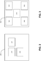
- the illumination system 140 comprises eleven light sources 150 (five light sources - in room 120, and six light sources - in room 130).
- the illumination system 140 could comprise any number of light sources 150 equal to or greater than two, which light sources could be placed at different places within the structure.
- the light sources 150 may comprise any suitable sources of light such as e.g. high/low pressure gas discharge sources, laser diodes, inorganic/organic light emitting diodes, incandescent sources, or halogen sources.
- the light output provided by the light sources 150 contribute to the total illumination provided by the illumination system 140 for illuminating at least parts of the structure 100.
- one object of the present invention is to group the light sources 150 in each room in distinct groups automatically.
- the general idea behind the automatic grouping process can be seen as involving three basic steps: measurement, grouping, and assignment.
- the measurement step at least one light source emits a light signal and a sound signal that can be detected by other light sources.
- the light sources receiving the signals can determine the strength at which the signal was received (i.e., "received intensity") and can, optionally, identify the source of the signals (i.e., which light source sent the signals). Since sound signals are analyzed, glass walls or wall partitions can be detected by e.g. ultrasound by virtue of their acoustic blocking properties.
- all of the light sources could be configured to emit a light signal and a sound signal to be measured by other light sources. Once all of the emitted light and sound signals have been detected, each light source will have a list of other light sources from which they can receive signals as well as the intensities of the received signals. The grouping step may then begin. There are various approaches that can be used to group light sources, based on the received signal strength readings. In general, by clustering the light sources according to the readings evaluated in view of certain pre-determined conditions, a picture builds up of light sources that could form part of the same group and light sources that seem to not belong to the same group.
- the assignment step may take place where light sources that form a group are assigned a shared group identity by which they can be addressed by switches and other control hardware.
- Such a grouping process typically would take place as a part of a commissioning phase, carried out e.g. during the initial installation of the illumination system, but may also be carried out at other times, and perhaps for a smaller area, when an update is required.
- the general idea of grouping described above may be implemented in various manners.
- the present description differentiates between so-called “centralized” and “de-centralized” implementations.
- a central controller such as e.g. a control unit 200 shown in Fig.2 , which controller can, by its nature, form a global picture of the complete illumination system.
- the operation is performed in distributed fashion by the systems components themselves (mainly, by the light sources themselves - e.g. light sources 150 configured to be as a light source 300 shown in Fig. 3 ), where only a limited view of the entire illumination system is available to each of the individual components.
- the central control unit plays a limited role or no role at all.
- the de-centralized implementation may be particularly useful in some installations because the distributed nature of the processing means that it is highly scalable. Therefore, despite potential difficulties associated with this implementation, this may be a preferred approach in many installations in practice.
- the processing unit 210 is the common element between the centralized implementation using the control unit 200 and the de-centralized implementation using the light sources such as the light source 300. Therefore, unless explicitly stated otherwise, functions of the processing unit 210 described below are applicable to both centralized and de-centralized implementations.
- the control unit 200 also includes a receiver 220 configured for obtaining the intensities of the light and sound signals detected by the light sources.
- each of the light sources 150 could be configured to provide the intensities they measured to the control unit 200 immediately after the light source measured the intensities.
- the light sources 150 could store the intensities they measure and only provide them to the control unit 200 when triggered to do so, e.g. by a triggering unit 230 which could also, optionally, be included within the control unit 200.
- the triggering unit 230 may also be used for providing a trigger to one or more light sources to start emitting light and sound signals to be measured by other light sources and/or for providing a trigger to the other light sources to start receiving and measuring the received light and sound signals.
- the control unit 200 could control initiation of the grouping process as a part of the commissioning of the illumination system. Implementing the system such that the light sources only start receiving and measuring signals when triggered to do so allows preserving energy consumption by the light sources because their light and sound receiving interfaces may be configured to be normally in an idle mode and only wake up to make the measurements when triggered to do so.
- the triggering unit 230 could control the sequence at which the light sources emit their signals.
- the triggering unit 230 could provide triggers to the different light sources sequentially, to make sure that when one light source is emitting its light and sound signals, all the other light sources are not emitting similar signals but only measuring the signals emitted by the first light source.
- the control unit 200 may further include a display (not shown in Fig. 2 ) for displaying to a user the final or intermediate results of the grouping process and for providing a user interface for controlling the light sources and other elements of the illumination system.
- the control unit 200 may further optionally includes a memory and a specifically designated control (RF/WiFi) unit (both not shown in Fig. 2 ) for controlling the light sources.
- RF/WiFi specifically designated control
- the control unit 200 is illustrated as a single unit, persons skilled in the art will realize that functionality of the individual elements illustrated in Fig. 2 to be within the control unit 200 could also be distributed among several other units, where e.g. some of the processing could be performed by the individual light sources.
- the light sources 150 could be configured as the light source 300, the elements of which are described below, except that such light sources don't need to have the complete, or any, functionality of the processing unit 210 shown in Fig. 3 because the functionality of that unit is already included in the control unit 200.
- All light sources, switches, sensors, and further controllers of the illumination system 140 could be linked via network to central control unit 200 and all of these devices could be individually identifiable to control unit 200 by their system-unique addresses and by device types and subtypes, such as e.g. downlighters versus wall washers.
- the light source 300 also at least includes a light receiver 320 configured for receiving light signals from other light sources and measuring their intensities and a sound receiver 330 configured for receiving sound signals from other light sources and measuring their intensities.
- the light source 300 may then either be able to process the received signals itself, by the processing unit 210, or provide the values of the detected light and sound intensities to another device for processing, such as e.g. to the control unit 200.
- the light source 300 may further, optionally, include a light emitter 340 and a sound emitter 350.
- each of the light sources 150 in the illumination system 140 includes both receivers and emitters of light and sound signals, then each of the light sources could be configured to fully participate in the grouping process not only by receiving but also by transmitting signals to be measured by other light sources.
- the sound receivers 330 and the sound transmitters 350 may already exist in the light sources as a part of an intelligent lighting control system that adapts automatically to the presence of people in a room, making this an attractive avenue to follow as the hardware of the existing light sources does not need to be significantly upgraded.
- a controller similar to that of the control unit 200 may also play a role, but be limited only to its' basic functions, such as e.g. controlling overall phase of the process (i.e., providing boundaries between measurement, grouping, and assignment steps.
- Fig. 4 is a flow diagram of method steps for automatic grouping of light sources using light and sound, according to one embodiment of the present invention. While the method steps are described in conjunction with the elements shown in Figs. 1-3 , persons skilled in the art will recognize that any system configured to perform the method steps, in any order, is within the scope of the present invention. In particular, references are made to at least a first, second, and third light sources, each of which could be one of the light sources 150. Numeral references (i.e., first, second, third) in the description and the claims are not intended to show any sequential order or anything else besides providing the differentiation between the various light sources.
- a first light source emits a light signal and a sound signal to be measured by other light sources of the illumination system.
- At least one light source a second light source, is able to detect and measure at least the intensities of both the light and the sound signal emitted by the first light source.
- the second light source may also be able to measure the TOF of the sound signal emitted by the first light source, as measured against the light signal emitted by the first light source.
- the second light source may be configured to measure its own light and sound signals, which may need to be provided to the processing unit 210 for calibration purposes.
- the light sources mounted on the ceiling may be configured to radiate the light of their light signals mostly downwards rather than sideways and the light detectors of the receiving light sources are then configured to detect the reflected light signals.
- the first light source may be a randomly chosen light source.
- the first light source may then be configured to begin the search procedure by broadcasting a "Start Search Of Neighboring Light sources" (SSONL) message, e.g. via the communication network of the illumination system 140, and also producing its light and sound signals to be detected by other light sources.
- the light sources in the proximity of the first light source may then receive the broadcasted message and measure the intensity of the received sound and light signals and the TOF of the received sound signal.
- the communication network is a CL network (described in greater detail below)
- the SSONL message is transmitted via CL and that message, in itself, may be the light signal emitted by the first light source for measurement by the other light sources.
- the second light source would then measure the intensity of the received light signal by measuring the intensity of the light encoding the SSONL message.
- the method of Fig. 4 may then begin with a step 410, where the processing unit 210 obtains at least the intensities (or derivatives thereof) of the light and sound signals emitted by the first light source as measured at the second light source.
- the processing unit 210 may also obtain in step 410 results of other measurements performed by the second light source, such as e.g. TOF measurements and measurements of its own light and sound signals. This information can be used by the processing unit 210 in steps 420 and 430 to e.g. advantageously eliminate ambiguities and improve the stability of an operational system.
- performing step 410 may mean that the processing unit 210 receives the intensity of the light signal emitted by the first light source from the light receiver 320 and receives the intensity of the sound signal emitted by the first light source from the sound receiver 330.
- performing step 410 may mean that the processing unit 210 receives the intensities of the light and sound signals emitted by the first light source, as measured by the second light source, from the second light source via the receiver 220.
- the control unit 200 may provide a trigger to the second light source to report its measurements.
- each emitting light source could be configured to e.g. emit their light and sound signals in a particular pre-determined pattern or in a particular range of frequencies so that the receiving light sources are able to identify a pair of light and sound signals received from a single emitting light source.
- the emitted light and sound signals include some kind of an identification of the emitting light source and/or the device type of the emitting light source.
- identification as well as other information which may need to be included in the light and sound signals, may be included in the signals by any type of appropriate encoding.
- the information may be included in the light signals emitted by the light sources using CL technique where information, represented as a data signal, is embedded into the light output of a light source by modulating a drive signal to be applied to the light source in response to the data signal.
- CL technique information, represented as a data signal
- the data signal could e.g. comprise an individual identifier code of the emitting light source.
- identifier of a light source refers to any codes that allow sufficient identification of individual light sources within the illumination system.
- the data signal may further comprise other information regarding the emitting light source and/or the illumination system, such as e.g. a device type of the light source, current light settings of the light source (e.g. the emitting intensities of the light and/or sound signals emitted by that light source) and/or additional information regarding e.g.
- the data signal is embedded into the light signal of the emitting light source multiple times (e.g. as N repetitions of the data code) to ensure reliable detection of CL data at the receiving end.
- the one or more of the emitting light sources may be configured to emit their light and sound signals multiple times, in order to ensure that the other light sources are able to reliably measure the received signals.
- step 420 the processing unit 210 determines the value of the grouping function, which value may be referred to as a Figure of Merit (FoM) for the purpose of grouping, using at least the values of the intensities of the received light and sound signals of the first light source obtained in step 410.
- the grouping function could be any appropriate function that takes as an input the values obtained in step 410 and allows the processing unit 210 to make a decision as to whether or not the first and second light sources should be assigned to the same group.
- step 430 the processing unit 210 determines whether the grouping function identified in step 420 satisfies one or more pre-determined conditions for grouping the first and second light sources into the same group.
- a grouping function could be dependent on the ratio between the intensity of the light signal and the intensity of the sound signal emitted by the first light source, as measured by the second light source.
- the pre-determined condition for grouping the light sources could then be that the grouping function, or at least the calculated ratio, is within a certain, pre-determined, range of values with which the processing unit 210 makes a comparison. For example, if the first light source is one of the light sources 150 in the room 130, while the second light source is one of the light sources 150 in the room 120 and the wall 110 is a glass wall, then the sound signal emitted by the first light source will be noticeably attenuated, which will be reflected in the calculated ratio between the received intensities of the light and sound signals.
- the first light source is one of the light sources 150 in the room 130 and the second light source is one of the light sources 150 in the room 120, but the wall 110 is an opaque wall partition that does not extend all the way up to the ceiling (not shown in Fig. 1 ) and the first light signal is configured to emit most of its light signal downwards
- the first light signal received by the second light source will be noticeably attenuated because a majority of it will not pass the opaque wall partition, which will, again, be reflected in the calculated ratio between the received intensities of the light and sound signals.
- a grouping function could be dependent on comparing each of the received intensities with respective pre-determined threshold values, resulting in the two light sources not being grouped if either intensity is smaller than its threshold.
- a grouping function could comprise components of each of these examples and be evaluated in light of multiple pre-determined conditions in order to obtain a more complete analysis of the first and second light sources with respect to one another.
- the received intensities of the light and sound signals emitted by the first light source may be normalized prior to calculating the ratio and/or comparing the values of these intensities to some threshold value.
- the normalization could be done with respect to the intensities of the light and sound signals emitted by and as measured by the second light source, which intensities could also be provided to the processing unit as a part of step 410.
- the normalization could be done with respect to the emitting intensities of the light and sound signals of the first light source, which intensities could also be provided to the processing unit as a part of step 410.
- the normalization could be done with respect to the TOF of the sound signal emitted by the first light source as measured by the second light source, which TOF could be provided to the processing unit as a part of step 410 as well.
- the operation of the grouping can be understood by considering the wider picture.
- the exponent n is typically modeled empirically and a higher value, e.g., 3.5 or 4, is often found to be a better match for observations.
- the UnitLoss term collects together all fixed losses and all fixed terms, including receiver sensitivity, that are substantially independent of distance between the light sources and, therefore, constant across all pairings of the same type.
- the PartitionLoss term accounts for the extra loss that may be incurred if the signal has to cross a wall, partition or some other barrier. Where no such partition exists, or where the partition is transparent, partition loss is zero. Where a partition exists that is non-transparent to either light or sound, the corresponding partition loss could be substantially higher. Therefore, in the first instance, for each transmission mode, partition loss may be estimated in order to determine whether two light sources are in the same room or not.
- the likelihood is that there exists an intentional partition that happens to be transparent to either light or sound.
- RSSI light RadiatedPower light ⁇ PL light
- RSSI sound RadiatedPower sound ⁇ PL sound
- RadiatedPower represents power of the signal as emitted by the first light source
- a grouping function that takes into account at least the measured RSSI readings, as well as possibly measured estimates for the distance between the light sources, external information on luminaire type and other pre-grouping data and so on, may be used to calculate an FoM for the link between each light source.
- a further level of grouping may then be applied at each light source by clustering the 'figure of merits' and thereby determining a range within which light sources are assumed to be in the same room and therefore candidates for grouping.
- all light sources may be assumed to be groups of one.
- a possible algorithm clustering may include the steps of finding the two groups with the closest FoMs, marking these two groups as part of the same new group, and repeating these two steps until a certain termination event.
- a termination event can be defined that stops the algorithm at a more suitable point.
- the grouping function will register a distinct jump in the FoM between two groups on opposite sides of the partition compared to groups on the same side. Since the algorithm identifies groups from the closest FoM upwards, this jump means that now groups that are on opposite sides of the partition are being grouped together. This is an appropriate point to stop. In the case of Fig. 1 , stopping at this point would result in having two groups, one on each side of the partition.
- the processing unit 210 may also take other, additional information, into account when making a decision on whether or not the first and second light sources should be grouped. For example, the processing unit 210 may take into consideration the nature and type of the light sources and e.g. determine that the first and second light sources do belong to the same group when the type of both light sources is a wall washer. In another example, the processing unit 210 may take into consideration other information (either received as a part of step 410 or pre-stored in the processing unit 210) such as location of windows, projectors, etc. within the structure 100.
- the processing unit 210 would have information, for example, that there is a projector and a screen in the room, and would have to divide the light sources in the room into two groups, namely light sources close to the screen and light sources further away from the screen.
- the processing unit 210 may be configured to restrict processing of signals in steps 420 and 430 to small areas (e.g., refurbished or reconfigured areas).
- the processing unit 210 may, for instance, be configured to never create a group with a diameter larger than 10 meters.
- the distance estimation can be based on TOF between the neighbors' and triangulation.
- the processing unit 210 may be configured to receive user input at some point during the processing of steps 420 and 430, thus making possible manual intervention on as-needed basis. Such user input may indicate to the processing unit 210 further considerations regarding e.g. combination or splitting of groups.
- the processing unit 210 included within each of the light sources makes the decision whether or not that light source should be grouped in the group with the light source from which it received and measured light and sound signals (e.g., the first light source) substantially independently from what else may happen in the illumination system, e.g. independently from what some other light sources measured.
- the processing unit 210 included within the control unit 200 of the centralized implementation may also take further information received from other light sources into consideration when deciding whether to group the first and second light sources together.
- step 440 the processing unit 210 assigns the first and second light sources to the same group. Otherwise, the method ends in step 450 where the first and the second light sources are not assigned to the same group.
- the light sources 300 group themselves. To finish off the procedure, the light sources need to communicate with each other to establish a collective group identity and process requests to join the group from candidate luminaires.
- the first light source may issue a 'group leader' signal.
- light sources that received that signal check their records and those that want to be part of that light source's group may issue 'join' requests, again according to a random back-off channel access strategy.
- the first light source may then consider these requests against its own list and either accepts the requesting light sources into its group or rejects their request.
- nearby controllers and other components of the illumination system may be configured to note new groups in their vicinity.
- the auto-assignment will be completed in this implementation wherever possible, while leaving the possibilities for manual assistance and fine-tuning requests on a case by case basis.
- the de-centralized implementation of the assignment step 440 may, additionally, implement processes for handling rejected, orphaned or otherwise incorrectly assigned light sources, processes for reassignment of group leader role to a e.g. better-located light source, and processes for relaying information between light sources at opposite ends of a long room.
- the light sources that are selected to be the group leaders of the individual groups may be configured to issue beacons to allow network update regarding changed group assignments.
- the processing unit 210 may be configured to assign each light source a locally-unique group ID.
- the control unit 200 may be configured to inform other components of the illumination system, e.g. other controllers, of the groups of light sources located near to them. Similar to the de-centralized implementation, the auto-assignment will be completed wherever possible, while leaving the possibilities for manual assistance and fine-tuning requests on a case by case basis.
- Embodiments of the present invention utilize the advantages of combining light with sound to help resolve ambiguous cases of the sort described. Additionally, since light and sound travel at vastly different rates, the availability of both allows the TOF of a one-way sound signal to be measured sufficiently precisely to be able to accurately determine the distance between two light sources. This information may be used to further guide the grouping process.
- Various embodiments of the invention may be implemented as a program product for use with a computer system, where the program(s) of the program product define functions of the embodiments (including the methods described herein).
- the program(s) can be contained on a variety of non-transitory computer-readable storage media, where, as used herein, the expression "non-transitory computer readable storage media" comprises all computer-readable media, with the sole exception being a transitory, propagating signal.
- the program(s) can be contained on a variety of transitory computer-readable storage media.
- Illustrative computer-readable storage media include, but are not limited to: (i) non-writable storage media (e.g., read-only memory devices within a computer such as CD-ROM disks readable by a CD-ROM drive, ROM chips or any type of solid-state non-volatile semiconductor memory) on which information is permanently stored; and (ii) writable storage media (e.g., flash memory, floppy disks within a diskette drive or hard-disk drive or any type of solid-state random-access semiconductor memory) on which alterable information is stored.
- the computer program may be run on the processing unit 210 described herein.
- aspects of the present invention may be implemented in hardware or software or in a combination of hardware and software.
Landscapes
- Circuit Arrangement For Electric Light Sources In General (AREA)
Claims (15)
- Verfahren zum Gruppieren von Lichtquellen in einem Beleuchtungssystem, wobei das Verfahren die folgenden Schritte umfasst:- Aussenden eines ersten Lichtsignals und eines ersten Schallsignals über eine erste Lichtquelle (150),gekennzeichnet durch die folgenden Schritte:- Verwenden einer Intensität des ersten Lichtsignals, wie es von einer zweiten Lichtquelle empfangen wird, und einer Intensität des ersten Schallsignals, wie es von der zweiten Lichtquelle empfangen wird, um einen Wert einer Gruppierungsfunktion zu bestimmen, und- Zuordnen der ersten Lichtquelle und der zweiten Lichtquelle zu einer gleichen Gruppe von Lichtquellen, wenn der bestimmte Wert der Gruppierungsfunktion eine oder mehrere vorgegebene Bedingungen erfüllt.
- Verfahren nach Anspruch 1, weiter umfassend das Auswählen der Gruppierungsfunktion, die von einem Verhältnis zwischen der Intensität des ersten Lichtsignals, wie es von der zweiten Lichtquelle empfangen wird, und der Intensität des ersten Schallsignals, wie es von der zweiten Lichtquelle empfangen wird, abhängig ist, und ein Auswählen der einen oder mehreren vorbestimmten Bedingungen, um eine Bedingung zu umfassen, bei der das Verhältnis innerhalb eines vorbestimmten Bereichs liegt.
- Verfahren nach den Ansprüchen 1 oder 2, weiter umfassend das Bestimmen einer Differenz zwischen der Zeit, in der das erste Lichtsignal von der zweiten Lichtquelle empfangen wird, und der Zeit, in der das erste Schallsignal von der zweiten Lichtquelle empfangen wird.
- Verfahren nach Anspruch 3, weiter umfassend das Auswählen der Gruppierungsfunktion, die von der bestimmten Differenz abhängig sein soll, und ein Auswählen der einen oder mehreren vorbestimmten Bedingungen, um eine Bedingung zu umfassen, bei der die bestimmte Differenz unter einem vorbestimmten Wert liegt.
- Verfahren nach den Ansprüchen 3 oder 4, weiter umfassend das Bereitstellen der Intensität des ersten Lichtsignals, wie es von der zweiten Lichtquelle empfangen wird, und der Intensität des ersten Schallsignals, wie es von der zweiten Lichtquelle empfangen wird, mit Werten, die auf die bestimmte Differenz normiert sind.
- Verfahren nach einem der Ansprüche 1-4, weiter umfassend das Bereitstellen der Intensität des ersten Lichtsignals, wie es von der zweiten Lichtquelle empfangen wird, mit einem Wert, der auf eine Intensität des ersten Lichtsignals normiert ist, wie es von der ersten Lichtquelle ausgesendet wird, und ein Bereitstellen der Intensität des ersten Schallsignals, wie es von der zweiten Lichtquelle empfangen wird, mit einem Wert, der auf eine Intensität des ersten Schallsignals normiert ist, wie es von der ersten Lichtquelle ausgesendet wird.
- Verfahren nach einem der vorstehenden Ansprüche, weiter umfassend das Bereitstellen von Informationen in mindestens einem des ersten Lichtsignals oder des ersten Schallsignals, die die Identität der ersten Lich tquelle anzeigen, und/oder von Informationen, die die Identität der Gruppe anzeigen, der die erste Lichtquelle zugeordnet werden soll.
- Steuereinheit (200), gekennzeichnet durch:einen Empfänger (220), der konfiguriert ist, um die Intensität eines ersten Lichtsignals, wie es von einer zweiten Lichtquelle empfangen wird, und die Intensität eines ersten Schallsignals, wie es von der zweiten Lichtquelle empfangen wird, zu erhalten; undeine Verarbeitungseinheit (210), die konfiguriert ist, um die Schritte des Verwendens der erhaltenen Intensität des ersten Lichtsignals, wie es von der zweiten Lichtquelle empfangen wird, und der erhaltenen Intensität des ersten Schallsignals, wie es von der zweiten Lichtquelle empfangen wird, um einen Wert einer Gruppierungsfunktion zu bestimmen, und des Zuordnens der zweiten Lichtquelle und einer ersten Lichtquelle, die das erste Lichtsignal und das erste Schallsignal an dieselbe Gruppe von Lichtquellen ausgesendet hat, durchzuführen, wenn der bestimmte Wert der Gruppierungsfunktion eine oder mehrere vorbestimmte Bedingungen erfüllt.
- Steuereinheit (200) nach Anspruch 8, wobei:der Empfänger (220) weiter konfiguriert ist, um die Intensität des ersten Lichtsignals, wie es von einer dritten Lichtquelle empfangen wird, und die Intensität des ersten Schallsignals, wie es von der dritten Lichtquelle empfangen wird, zu erhalten, unddie Verarbeitungseinheit (210) weiter konfiguriert ist, um die Intensität des ersten Lichtsignals, wie es von der dritten Lichtquelle empfangen wird, und die Intensität des ersten Schallsignals, wie es von der dritten Lichtquelle empfangen wird, zu verwenden, um den Wert der Gruppierungsfunktion zu bestimmen und die erste Lichtquelle und die dritte Lichtquelle derselben Gruppe von Lichtquellen zuzuordnen, wenn der bestimmte Wert der Gruppierungsfunktion die einen oder mehreren vorbestimmten Bedingungen erfüllt.
- Steuereinheit (200) nach den Ansprüchen 8 oder 9, weiter umfassend eine Auslöseeinheit (230), die konfiguriert ist, um der ersten Lichtquelle einen Auslöser zum Aussenden des ersten Lichtsignals und des ersten Schallsignals und/oder der zweiten Lichtquelle einen Auslöser zum Empfangen der ersten Licht- und Schallsignale und zum Bestimmen der Intensitäten der ersten Licht- und Schallsignale bereitzustellen.
- Steuereinheit (200) nach Anspruch 10, wobei die Auslöseeinheit (230) weiter konfiguriert ist, um einer vierten Lichtquelle einen Auslöser zum Aussenden eines vierten Lichtsignals und eines vierten Schallsignals bereitzustellen und/oder um einer oder mehrerer der ersten Lichtquelle und der zweiten Lichtquelle einen Auslöser zum Empfangen der vierten Licht- und Schallsignale und zum Bestimmen der Intensitäten der vierten Licht- und Schallsignale bereitzustellen.
- Steuereinheit (200) nach Anspruch 11, wobei der Auslöser für die erste Lichtquelle und der Auslöser für die vierte Lichtquelle nacheinander bereitgestellt sind.
- Eine zweite Lichtquelle (300), umfassend:einen Lichtempfänger (320), der zum Empfangen des ersten Lichtsignals und zum Bestimmen der Intensität des ersten Lichtsignals, wie es von der zweiten Lichtquelle empfangen wird, konfiguriert ist;einen Schallempfänger (330), der zum Empfangen des ersten Schallsignals konfiguriert ist, das die Intensität des ersten Schallsignals bestimmt, wie es von der zweiten Lichtquelle empfangen wird; undeine Verarbeitungseinheit (210), die zum Ausführen der Schritte des Verfahrens nach einem oder mehreren der Ansprüche 1-7 konfiguriert ist.
- Zweite Lichtquelle (300) nach Anspruch 13, weiter umfassend einen Lichtsender, der zum Aussenden eines zweiten Lichtsignals konfiguriert ist, und einen Schallsender, der zum Aussenden eines zweiten Schallsignals konfiguriert ist.
- Computerprogramm, der Softwarecodebereiche umfasst, die konfiguriert sind, um, wenn sie auf einer Verarbeitungseinheit ausgeführt werden, die Schritte des Verfahrens nach einem oder mehreren der Ansprüche 1-7 auszuführen.
Applications Claiming Priority (2)
| Application Number | Priority Date | Filing Date | Title |
|---|---|---|---|
| US201361759447P | 2013-02-01 | 2013-02-01 | |
| PCT/IB2014/058485 WO2014118676A1 (en) | 2013-02-01 | 2014-01-23 | Automatic grouping via light and sound |
Publications (2)
| Publication Number | Publication Date |
|---|---|
| EP2952064A1 EP2952064A1 (de) | 2015-12-09 |
| EP2952064B1 true EP2952064B1 (de) | 2019-06-26 |
Family
ID=50115930
Family Applications (1)
| Application Number | Title | Priority Date | Filing Date |
|---|---|---|---|
| EP14705216.1A Active EP2952064B1 (de) | 2013-02-01 | 2014-01-23 | Automatische gruppierung über licht und ton |
Country Status (7)
| Country | Link |
|---|---|
| US (1) | US9609723B2 (de) |
| EP (1) | EP2952064B1 (de) |
| JP (2) | JP5982067B2 (de) |
| CN (1) | CN104956773B (de) |
| BR (1) | BR112015018093A2 (de) |
| MX (1) | MX2015009714A (de) |
| WO (1) | WO2014118676A1 (de) |
Cited By (1)
| Publication number | Priority date | Publication date | Assignee | Title |
|---|---|---|---|---|
| EP4672868A1 (de) * | 2024-06-28 | 2025-12-31 | Helvar Oy Ab | Positionsschätzung in einem beleuchtungssteuerungsnetzwerk |
Families Citing this family (11)
| Publication number | Priority date | Publication date | Assignee | Title |
|---|---|---|---|---|
| CN108370628B (zh) * | 2015-09-04 | 2020-04-21 | 飞利浦照明控股有限公司 | 允许无线通信的灯 |
| EP3345462B1 (de) * | 2015-09-04 | 2020-07-15 | Signify Holding B.V. | Automatisches gruppieren mehrerer drahtlos kommunizierender lampeneinheiten innerhalb einer leuchte |
| US9949331B1 (en) * | 2017-05-01 | 2018-04-17 | Gooee Limited | Automated luminaire identification and group assignment |
| US10448482B2 (en) | 2017-05-02 | 2019-10-15 | Jdrf Electromag Engineering Inc. | System and method for automatically creating and operating a functional association of lights |
| US10021771B1 (en) * | 2017-05-02 | 2018-07-10 | Jdrf Electromag Engineering Inc. | System and method for automatically creating and operating a functional association of lights |
| US11602034B2 (en) * | 2017-05-08 | 2023-03-07 | Signify Holding B.V. | Forming groups of devices by analyzing device control information |
| US10405402B2 (en) * | 2017-10-18 | 2019-09-03 | Usai, Llc | Power conservation for distributed lighting system |
| EP3624561A1 (de) | 2018-09-17 | 2020-03-18 | Helvar Oy Ab | Verfahren und anordnung zur dynamischen gruppierung von vorrichtungen in einem beleuchtungssystem |
| IT201900018161A1 (it) * | 2019-10-08 | 2021-04-08 | Ledworks Srl | Sistema di illuminazione e metodo di controllo di detto sistema |
| JP7411884B2 (ja) * | 2019-10-30 | 2024-01-12 | パナソニックIpマネジメント株式会社 | 照明システム、電源装置、照明器具、マッピング方法、及びプログラム |
| CN121056032A (zh) * | 2024-05-29 | 2025-12-02 | 华为技术有限公司 | 一种多模态编解码信息传输的方法以及电子设备 |
Family Cites Families (14)
| Publication number | Priority date | Publication date | Assignee | Title |
|---|---|---|---|---|
| JP2002299071A (ja) | 2001-03-29 | 2002-10-11 | Mitsubishi Electric Corp | 照明制御システム装置 |
| DE602005009815D1 (de) | 2004-04-02 | 2008-10-30 | Koninkl Philips Electronics Nv | Einrichtung zum beleuchten eines raums |
| CN101138281A (zh) | 2005-03-11 | 2008-03-05 | 皇家飞利浦电子股份有限公司 | 用于无线照明分配的墙检测 |
| WO2006095316A1 (en) * | 2005-03-11 | 2006-09-14 | Koninklijke Philips Electronics N.V. | Grouping wireless lighting nodes according to a building room layout |
| JP5030943B2 (ja) * | 2005-04-22 | 2012-09-19 | コーニンクレッカ フィリップス エレクトロニクス エヌ ヴィ | 照明装置の制御方法と制御システム |
| US20070160373A1 (en) * | 2005-12-22 | 2007-07-12 | Palo Alto Research Center Incorporated | Distributed illumination and sensing system |
| EP1994686B1 (de) | 2006-03-06 | 2018-08-01 | Koninklijke Philips N.V. | Verwendung von positionen zur knotengruppierung |
| WO2007102097A1 (en) * | 2006-03-07 | 2007-09-13 | Philips Intellectual Property & Standards Gmbh | Lighting system with lighting units using optical communication |
| JP5198445B2 (ja) * | 2006-06-29 | 2013-05-15 | コーニンクレッカ フィリップス エレクトロニクス エヌ ヴィ | 自律限定ネットワークの実現及び作動 |
| CN102165849B (zh) | 2008-09-26 | 2016-08-03 | 皇家飞利浦电子股份有限公司 | 用于多个光源的自动调试的系统和方法 |
| JP2012518888A (ja) | 2009-02-26 | 2012-08-16 | コーニンクレッカ フィリップス エレクトロニクス エヌ ヴィ | ネットワーク接続された制御システムの装置の自動立ち上げ |
| US8159156B2 (en) * | 2009-08-10 | 2012-04-17 | Redwood Systems, Inc. | Lighting systems and methods of auto-commissioning |
| JP5767228B2 (ja) * | 2009-09-14 | 2015-08-19 | コーニンクレッカ フィリップス エヌ ヴェ | 符号化光の送信及び受信 |
| US20140022917A1 (en) * | 2012-07-17 | 2014-01-23 | Procter And Gamble, Inc. | Home network of connected consumer devices |
-
2014
- 2014-01-23 EP EP14705216.1A patent/EP2952064B1/de active Active
- 2014-01-23 MX MX2015009714A patent/MX2015009714A/es not_active Application Discontinuation
- 2014-01-23 CN CN201480006947.1A patent/CN104956773B/zh not_active Expired - Fee Related
- 2014-01-23 US US14/765,022 patent/US9609723B2/en not_active Expired - Fee Related
- 2014-01-23 BR BR112015018093A patent/BR112015018093A2/pt not_active IP Right Cessation
- 2014-01-23 WO PCT/IB2014/058485 patent/WO2014118676A1/en not_active Ceased
- 2014-01-23 JP JP2015553222A patent/JP5982067B2/ja not_active Expired - Fee Related
-
2016
- 2016-07-29 JP JP2016149162A patent/JP6157037B2/ja not_active Expired - Fee Related
Non-Patent Citations (1)
| Title |
|---|
| None * |
Cited By (1)
| Publication number | Priority date | Publication date | Assignee | Title |
|---|---|---|---|---|
| EP4672868A1 (de) * | 2024-06-28 | 2025-12-31 | Helvar Oy Ab | Positionsschätzung in einem beleuchtungssteuerungsnetzwerk |
Also Published As
| Publication number | Publication date |
|---|---|
| JP6157037B2 (ja) | 2017-07-05 |
| CN104956773B (zh) | 2017-09-15 |
| JP5982067B2 (ja) | 2016-08-31 |
| CN104956773A (zh) | 2015-09-30 |
| US9609723B2 (en) | 2017-03-28 |
| JP2016507130A (ja) | 2016-03-07 |
| JP2016213199A (ja) | 2016-12-15 |
| EP2952064A1 (de) | 2015-12-09 |
| MX2015009714A (es) | 2015-11-06 |
| WO2014118676A1 (en) | 2014-08-07 |
| US20150373812A1 (en) | 2015-12-24 |
| BR112015018093A2 (pt) | 2017-07-18 |
Similar Documents
| Publication | Publication Date | Title |
|---|---|---|
| EP2952064B1 (de) | Automatische gruppierung über licht und ton | |
| CN101479995B (zh) | 自治的有限网络实现与试运转 | |
| US9253040B2 (en) | Grouping wireless lighting nodes according to a building room layout | |
| US11343897B2 (en) | Controller for controlling a wireless network to perform radiofrequency-based motion detection | |
| CN109791191B (zh) | 信标验证设备 | |
| CN101138281A (zh) | 用于无线照明分配的墙检测 | |
| EP4059322B1 (de) | Änderung der sende- und/oder empfangseigenschaften zum erkennen anderer ereignisse als der anwesenheit von personen | |
| US20180049293A1 (en) | Presence request via light adjustment | |
| US20230142829A1 (en) | Autonomous room boundary detection and classification with low resolution sensors | |
| EP3672335B1 (de) | Verfahren und vorrichtung zur inbetriebnahme eines beleuchtungssystems | |
| EP4203623A1 (de) | Beleuchtungssteuerung | |
| EP4672868A1 (de) | Positionsschätzung in einem beleuchtungssteuerungsnetzwerk |
Legal Events
| Date | Code | Title | Description |
|---|---|---|---|
| PUAI | Public reference made under article 153(3) epc to a published international application that has entered the european phase |
Free format text: ORIGINAL CODE: 0009012 |
|
| 17P | Request for examination filed |
Effective date: 20150901 |
|
| AK | Designated contracting states |
Kind code of ref document: A1 Designated state(s): AL AT BE BG CH CY CZ DE DK EE ES FI FR GB GR HR HU IE IS IT LI LT LU LV MC MK MT NL NO PL PT RO RS SE SI SK SM TR |
|
| AX | Request for extension of the european patent |
Extension state: BA ME |
|
| DAX | Request for extension of the european patent (deleted) | ||
| RAP1 | Party data changed (applicant data changed or rights of an application transferred) |
Owner name: PHILIPS LIGHTING HOLDING B.V. |
|
| STAA | Information on the status of an ep patent application or granted ep patent |
Free format text: STATUS: EXAMINATION IS IN PROGRESS |
|
| 17Q | First examination report despatched |
Effective date: 20170324 |
|
| RIN1 | Information on inventor provided before grant (corrected) |
Inventor name: FERI, LORENZO Inventor name: PASVEER, WILLEM FRANKE Inventor name: RIETMAN, RONALD Inventor name: DAVIES, ROBERT JAMES |
|
| RAP1 | Party data changed (applicant data changed or rights of an application transferred) |
Owner name: PHILIPS LIGHTING HOLDING B.V. |
|
| GRAP | Despatch of communication of intention to grant a patent |
Free format text: ORIGINAL CODE: EPIDOSNIGR1 |
|
| STAA | Information on the status of an ep patent application or granted ep patent |
Free format text: STATUS: GRANT OF PATENT IS INTENDED |
|
| INTG | Intention to grant announced |
Effective date: 20190122 |
|
| RAP1 | Party data changed (applicant data changed or rights of an application transferred) |
Owner name: SIGNIFY HOLDING B.V. |
|
| GRAS | Grant fee paid |
Free format text: ORIGINAL CODE: EPIDOSNIGR3 |
|
| GRAA | (expected) grant |
Free format text: ORIGINAL CODE: 0009210 |
|
| STAA | Information on the status of an ep patent application or granted ep patent |
Free format text: STATUS: THE PATENT HAS BEEN GRANTED |
|
| AK | Designated contracting states |
Kind code of ref document: B1 Designated state(s): AL AT BE BG CH CY CZ DE DK EE ES FI FR GB GR HR HU IE IS IT LI LT LU LV MC MK MT NL NO PL PT RO RS SE SI SK SM TR |
|
| REG | Reference to a national code |
Ref country code: GB Ref legal event code: FG4D |
|
| REG | Reference to a national code |
Ref country code: CH Ref legal event code: EP |
|
| REG | Reference to a national code |
Ref country code: AT Ref legal event code: REF Ref document number: 1149835 Country of ref document: AT Kind code of ref document: T Effective date: 20190715 |
|
| REG | Reference to a national code |
Ref country code: DE Ref legal event code: R096 Ref document number: 602014049020 Country of ref document: DE |
|
| REG | Reference to a national code |
Ref country code: IE Ref legal event code: FG4D |
|
| REG | Reference to a national code |
Ref country code: NL Ref legal event code: MP Effective date: 20190626 |
|
| PG25 | Lapsed in a contracting state [announced via postgrant information from national office to epo] |
Ref country code: FI Free format text: LAPSE BECAUSE OF FAILURE TO SUBMIT A TRANSLATION OF THE DESCRIPTION OR TO PAY THE FEE WITHIN THE PRESCRIBED TIME-LIMIT Effective date: 20190626 Ref country code: NO Free format text: LAPSE BECAUSE OF FAILURE TO SUBMIT A TRANSLATION OF THE DESCRIPTION OR TO PAY THE FEE WITHIN THE PRESCRIBED TIME-LIMIT Effective date: 20190926 Ref country code: LT Free format text: LAPSE BECAUSE OF FAILURE TO SUBMIT A TRANSLATION OF THE DESCRIPTION OR TO PAY THE FEE WITHIN THE PRESCRIBED TIME-LIMIT Effective date: 20190626 Ref country code: HR Free format text: LAPSE BECAUSE OF FAILURE TO SUBMIT A TRANSLATION OF THE DESCRIPTION OR TO PAY THE FEE WITHIN THE PRESCRIBED TIME-LIMIT Effective date: 20190626 Ref country code: SE Free format text: LAPSE BECAUSE OF FAILURE TO SUBMIT A TRANSLATION OF THE DESCRIPTION OR TO PAY THE FEE WITHIN THE PRESCRIBED TIME-LIMIT Effective date: 20190626 Ref country code: AL Free format text: LAPSE BECAUSE OF FAILURE TO SUBMIT A TRANSLATION OF THE DESCRIPTION OR TO PAY THE FEE WITHIN THE PRESCRIBED TIME-LIMIT Effective date: 20190626 |
|
| REG | Reference to a national code |
Ref country code: LT Ref legal event code: MG4D |
|
| PG25 | Lapsed in a contracting state [announced via postgrant information from national office to epo] |
Ref country code: BG Free format text: LAPSE BECAUSE OF FAILURE TO SUBMIT A TRANSLATION OF THE DESCRIPTION OR TO PAY THE FEE WITHIN THE PRESCRIBED TIME-LIMIT Effective date: 20190926 Ref country code: LV Free format text: LAPSE BECAUSE OF FAILURE TO SUBMIT A TRANSLATION OF THE DESCRIPTION OR TO PAY THE FEE WITHIN THE PRESCRIBED TIME-LIMIT Effective date: 20190626 Ref country code: RS Free format text: LAPSE BECAUSE OF FAILURE TO SUBMIT A TRANSLATION OF THE DESCRIPTION OR TO PAY THE FEE WITHIN THE PRESCRIBED TIME-LIMIT Effective date: 20190626 Ref country code: GR Free format text: LAPSE BECAUSE OF FAILURE TO SUBMIT A TRANSLATION OF THE DESCRIPTION OR TO PAY THE FEE WITHIN THE PRESCRIBED TIME-LIMIT Effective date: 20190927 |
|
| REG | Reference to a national code |
Ref country code: AT Ref legal event code: MK05 Ref document number: 1149835 Country of ref document: AT Kind code of ref document: T Effective date: 20190626 |
|
| PG25 | Lapsed in a contracting state [announced via postgrant information from national office to epo] |
Ref country code: SK Free format text: LAPSE BECAUSE OF FAILURE TO SUBMIT A TRANSLATION OF THE DESCRIPTION OR TO PAY THE FEE WITHIN THE PRESCRIBED TIME-LIMIT Effective date: 20190626 Ref country code: PT Free format text: LAPSE BECAUSE OF FAILURE TO SUBMIT A TRANSLATION OF THE DESCRIPTION OR TO PAY THE FEE WITHIN THE PRESCRIBED TIME-LIMIT Effective date: 20191028 Ref country code: AT Free format text: LAPSE BECAUSE OF FAILURE TO SUBMIT A TRANSLATION OF THE DESCRIPTION OR TO PAY THE FEE WITHIN THE PRESCRIBED TIME-LIMIT Effective date: 20190626 Ref country code: EE Free format text: LAPSE BECAUSE OF FAILURE TO SUBMIT A TRANSLATION OF THE DESCRIPTION OR TO PAY THE FEE WITHIN THE PRESCRIBED TIME-LIMIT Effective date: 20190626 Ref country code: NL Free format text: LAPSE BECAUSE OF FAILURE TO SUBMIT A TRANSLATION OF THE DESCRIPTION OR TO PAY THE FEE WITHIN THE PRESCRIBED TIME-LIMIT Effective date: 20190626 Ref country code: CZ Free format text: LAPSE BECAUSE OF FAILURE TO SUBMIT A TRANSLATION OF THE DESCRIPTION OR TO PAY THE FEE WITHIN THE PRESCRIBED TIME-LIMIT Effective date: 20190626 Ref country code: RO Free format text: LAPSE BECAUSE OF FAILURE TO SUBMIT A TRANSLATION OF THE DESCRIPTION OR TO PAY THE FEE WITHIN THE PRESCRIBED TIME-LIMIT Effective date: 20190626 |
|
| PG25 | Lapsed in a contracting state [announced via postgrant information from national office to epo] |
Ref country code: ES Free format text: LAPSE BECAUSE OF FAILURE TO SUBMIT A TRANSLATION OF THE DESCRIPTION OR TO PAY THE FEE WITHIN THE PRESCRIBED TIME-LIMIT Effective date: 20190626 Ref country code: IS Free format text: LAPSE BECAUSE OF FAILURE TO SUBMIT A TRANSLATION OF THE DESCRIPTION OR TO PAY THE FEE WITHIN THE PRESCRIBED TIME-LIMIT Effective date: 20191026 Ref country code: IT Free format text: LAPSE BECAUSE OF FAILURE TO SUBMIT A TRANSLATION OF THE DESCRIPTION OR TO PAY THE FEE WITHIN THE PRESCRIBED TIME-LIMIT Effective date: 20190626 Ref country code: SM Free format text: LAPSE BECAUSE OF FAILURE TO SUBMIT A TRANSLATION OF THE DESCRIPTION OR TO PAY THE FEE WITHIN THE PRESCRIBED TIME-LIMIT Effective date: 20190626 |
|
| PG25 | Lapsed in a contracting state [announced via postgrant information from national office to epo] |
Ref country code: TR Free format text: LAPSE BECAUSE OF FAILURE TO SUBMIT A TRANSLATION OF THE DESCRIPTION OR TO PAY THE FEE WITHIN THE PRESCRIBED TIME-LIMIT Effective date: 20190626 |
|
| PG25 | Lapsed in a contracting state [announced via postgrant information from national office to epo] |
Ref country code: PL Free format text: LAPSE BECAUSE OF FAILURE TO SUBMIT A TRANSLATION OF THE DESCRIPTION OR TO PAY THE FEE WITHIN THE PRESCRIBED TIME-LIMIT Effective date: 20190626 Ref country code: DK Free format text: LAPSE BECAUSE OF FAILURE TO SUBMIT A TRANSLATION OF THE DESCRIPTION OR TO PAY THE FEE WITHIN THE PRESCRIBED TIME-LIMIT Effective date: 20190626 |
|
| PG25 | Lapsed in a contracting state [announced via postgrant information from national office to epo] |
Ref country code: IS Free format text: LAPSE BECAUSE OF FAILURE TO SUBMIT A TRANSLATION OF THE DESCRIPTION OR TO PAY THE FEE WITHIN THE PRESCRIBED TIME-LIMIT Effective date: 20200224 |
|
| REG | Reference to a national code |
Ref country code: DE Ref legal event code: R097 Ref document number: 602014049020 Country of ref document: DE |
|
| PLBE | No opposition filed within time limit |
Free format text: ORIGINAL CODE: 0009261 |
|
| STAA | Information on the status of an ep patent application or granted ep patent |
Free format text: STATUS: NO OPPOSITION FILED WITHIN TIME LIMIT |
|
| PG2D | Information on lapse in contracting state deleted |
Ref country code: IS |
|
| 26N | No opposition filed |
Effective date: 20200603 |
|
| PG25 | Lapsed in a contracting state [announced via postgrant information from national office to epo] |
Ref country code: MC Free format text: LAPSE BECAUSE OF FAILURE TO SUBMIT A TRANSLATION OF THE DESCRIPTION OR TO PAY THE FEE WITHIN THE PRESCRIBED TIME-LIMIT Effective date: 20190626 Ref country code: SI Free format text: LAPSE BECAUSE OF FAILURE TO SUBMIT A TRANSLATION OF THE DESCRIPTION OR TO PAY THE FEE WITHIN THE PRESCRIBED TIME-LIMIT Effective date: 20190626 |
|
| REG | Reference to a national code |
Ref country code: CH Ref legal event code: PL |
|
| REG | Reference to a national code |
Ref country code: BE Ref legal event code: MM Effective date: 20200131 |
|
| PG25 | Lapsed in a contracting state [announced via postgrant information from national office to epo] |
Ref country code: LU Free format text: LAPSE BECAUSE OF NON-PAYMENT OF DUE FEES Effective date: 20200123 |
|
| PG25 | Lapsed in a contracting state [announced via postgrant information from national office to epo] |
Ref country code: LI Free format text: LAPSE BECAUSE OF NON-PAYMENT OF DUE FEES Effective date: 20200131 Ref country code: CH Free format text: LAPSE BECAUSE OF NON-PAYMENT OF DUE FEES Effective date: 20200131 Ref country code: BE Free format text: LAPSE BECAUSE OF NON-PAYMENT OF DUE FEES Effective date: 20200131 |
|
| PG25 | Lapsed in a contracting state [announced via postgrant information from national office to epo] |
Ref country code: IE Free format text: LAPSE BECAUSE OF NON-PAYMENT OF DUE FEES Effective date: 20200123 |
|
| PG25 | Lapsed in a contracting state [announced via postgrant information from national office to epo] |
Ref country code: MT Free format text: LAPSE BECAUSE OF FAILURE TO SUBMIT A TRANSLATION OF THE DESCRIPTION OR TO PAY THE FEE WITHIN THE PRESCRIBED TIME-LIMIT Effective date: 20190626 Ref country code: CY Free format text: LAPSE BECAUSE OF FAILURE TO SUBMIT A TRANSLATION OF THE DESCRIPTION OR TO PAY THE FEE WITHIN THE PRESCRIBED TIME-LIMIT Effective date: 20190626 |
|
| PG25 | Lapsed in a contracting state [announced via postgrant information from national office to epo] |
Ref country code: MK Free format text: LAPSE BECAUSE OF FAILURE TO SUBMIT A TRANSLATION OF THE DESCRIPTION OR TO PAY THE FEE WITHIN THE PRESCRIBED TIME-LIMIT Effective date: 20190626 |
|
| PGFP | Annual fee paid to national office [announced via postgrant information from national office to epo] |
Ref country code: FR Payment date: 20230124 Year of fee payment: 10 |
|
| PGFP | Annual fee paid to national office [announced via postgrant information from national office to epo] |
Ref country code: GB Payment date: 20230124 Year of fee payment: 10 Ref country code: DE Payment date: 20230328 Year of fee payment: 10 |
|
| P01 | Opt-out of the competence of the unified patent court (upc) registered |
Effective date: 20230421 |
|
| REG | Reference to a national code |
Ref country code: DE Ref legal event code: R119 Ref document number: 602014049020 Country of ref document: DE |
|
| GBPC | Gb: european patent ceased through non-payment of renewal fee |
Effective date: 20240123 |
|
| PG25 | Lapsed in a contracting state [announced via postgrant information from national office to epo] |
Ref country code: DE Free format text: LAPSE BECAUSE OF NON-PAYMENT OF DUE FEES Effective date: 20240801 |
|
| PG25 | Lapsed in a contracting state [announced via postgrant information from national office to epo] |
Ref country code: GB Free format text: LAPSE BECAUSE OF NON-PAYMENT OF DUE FEES Effective date: 20240123 |
|
| PG25 | Lapsed in a contracting state [announced via postgrant information from national office to epo] |
Ref country code: FR Free format text: LAPSE BECAUSE OF NON-PAYMENT OF DUE FEES Effective date: 20240131 |
|
| PG25 | Lapsed in a contracting state [announced via postgrant information from national office to epo] |
Ref country code: GB Free format text: LAPSE BECAUSE OF NON-PAYMENT OF DUE FEES Effective date: 20240123 Ref country code: FR Free format text: LAPSE BECAUSE OF NON-PAYMENT OF DUE FEES Effective date: 20240131 Ref country code: DE Free format text: LAPSE BECAUSE OF NON-PAYMENT OF DUE FEES Effective date: 20240801 |