EP2951459B1 - Shock absorber with variable damping profile - Google Patents
Shock absorber with variable damping profile Download PDFInfo
- Publication number
- EP2951459B1 EP2951459B1 EP14703695.8A EP14703695A EP2951459B1 EP 2951459 B1 EP2951459 B1 EP 2951459B1 EP 14703695 A EP14703695 A EP 14703695A EP 2951459 B1 EP2951459 B1 EP 2951459B1
- Authority
- EP
- European Patent Office
- Prior art keywords
- shock tube
- external cylinder
- depth
- group
- energy absorption
- Prior art date
- Legal status (The legal status is an assumption and is not a legal conclusion. Google has not performed a legal analysis and makes no representation as to the accuracy of the status listed.)
- Active
Links
Images


Classifications
-
- F—MECHANICAL ENGINEERING; LIGHTING; HEATING; WEAPONS; BLASTING
- F16—ENGINEERING ELEMENTS AND UNITS; GENERAL MEASURES FOR PRODUCING AND MAINTAINING EFFECTIVE FUNCTIONING OF MACHINES OR INSTALLATIONS; THERMAL INSULATION IN GENERAL
- F16F—SPRINGS; SHOCK-ABSORBERS; MEANS FOR DAMPING VIBRATION
- F16F9/00—Springs, vibration-dampers, shock-absorbers, or similarly-constructed movement-dampers using a fluid or the equivalent as damping medium
- F16F9/32—Details
- F16F9/50—Special means providing automatic damping adjustment, i.e. self-adjustment of damping by particular sliding movements of a valve element, other than flexions or displacement of valve discs; Special means providing self-adjustment of spring characteristics
- F16F9/512—Means responsive to load action, i.e. static load on the damper or dynamic fluid pressure changes in the damper, e.g. due to changes in velocity
-
- F—MECHANICAL ENGINEERING; LIGHTING; HEATING; WEAPONS; BLASTING
- F16—ENGINEERING ELEMENTS AND UNITS; GENERAL MEASURES FOR PRODUCING AND MAINTAINING EFFECTIVE FUNCTIONING OF MACHINES OR INSTALLATIONS; THERMAL INSULATION IN GENERAL
- F16F—SPRINGS; SHOCK-ABSORBERS; MEANS FOR DAMPING VIBRATION
- F16F9/00—Springs, vibration-dampers, shock-absorbers, or similarly-constructed movement-dampers using a fluid or the equivalent as damping medium
- F16F9/32—Details
- F16F9/34—Special valve constructions; Shape or construction of throttling passages
- F16F9/346—Throttling passages in the form of slots arranged in cylinder walls
-
- F—MECHANICAL ENGINEERING; LIGHTING; HEATING; WEAPONS; BLASTING
- F16—ENGINEERING ELEMENTS AND UNITS; GENERAL MEASURES FOR PRODUCING AND MAINTAINING EFFECTIVE FUNCTIONING OF MACHINES OR INSTALLATIONS; THERMAL INSULATION IN GENERAL
- F16F—SPRINGS; SHOCK-ABSORBERS; MEANS FOR DAMPING VIBRATION
- F16F9/00—Springs, vibration-dampers, shock-absorbers, or similarly-constructed movement-dampers using a fluid or the equivalent as damping medium
- F16F9/32—Details
- F16F9/44—Means on or in the damper for manual or non-automatic adjustment; such means combined with temperature correction
-
- F—MECHANICAL ENGINEERING; LIGHTING; HEATING; WEAPONS; BLASTING
- F16—ENGINEERING ELEMENTS AND UNITS; GENERAL MEASURES FOR PRODUCING AND MAINTAINING EFFECTIVE FUNCTIONING OF MACHINES OR INSTALLATIONS; THERMAL INSULATION IN GENERAL
- F16F—SPRINGS; SHOCK-ABSORBERS; MEANS FOR DAMPING VIBRATION
- F16F9/00—Springs, vibration-dampers, shock-absorbers, or similarly-constructed movement-dampers using a fluid or the equivalent as damping medium
- F16F9/32—Details
- F16F9/48—Arrangements for providing different damping effects at different parts of the stroke
Definitions
- US2004094376 A1 discloses a shock absorber includes a body having an outer cylinder which rotates relative to an inner cylinder to provide an adjustable damping force through fluid bypass.
- US3840097 A discloses an adjustable energy absorber including a housing having a ram slidably extending therefrom.
- US4059175 A discloses a shock absorber for providing a linear decelerating force to a machine part by means of a piston which forces fluid through a series of orifices formed by the coaction of holes in the piston cylinder and grooves formed on the internal diameter of a sleeve which fits over the cylinder.
- EP1266149 A1 discloses a hydraulic shock absorber (1) comprising a shock absorber body (16) wherein is provided a compression chamber in which slides a piston (3) and its rod for compressing a damping fluid which it draws with drawing means.
- US 4057236 discloses an adjustable energy absorber including a housing having a ram slidably extending therefrom.
- a first control sleeve divides the housing into a pair of fluid chambers, which sleeve has an axially extending row of openings to provide communication between the two chambers.
- a second control sleeve surrounds the first sleeve and is nonrotatably connected thereto.
- the device disclosed herein incorporates a diverse range of uses within a single shock absorber device.
- the device disclosed herein is a novel combination of interaction between various components (e.g., piston head, shock tube, cylinder end, external cylinder, and adjustment mechanism) within a single shock absorber. Interaction of this degree is not found elsewhere in industry, where the highest degree of complexity in previous devices is limited to interaction between, for example, three parts. When the components disclosed herein are considered together and designed as an interrelated assembly, the ability to incorporate such a diverse range of uses within a single device emerges.
- One example embodiment of the present invention is an energy absorption device that includes an external cylinder housing member, shock tube, piston, and accumulator.
- the external cylinder has a distal end, a proximal end, an interior wall, and a flow channel formed on the interior wall of the external cylinder.
- the flow channel substantially extends along the length of the external cylinder and is in fluid communication with the accumulator.
- the piston includes a head portion and a rod portion. The head portion is slidably retained within the shock tube, and the rod portion extends from the head portion through the proximal end of the external cylinder and engages with an external body in motion.
- the accumulator is contained within the external cylinder and collects fluid from the interior of the shock tube when the head portion of the piston moves toward the distal end of the external cylinder.
- the shock tube is rotatably secured within the external cylinder and has an interior surface, an exterior surface, and a group of inline holes along the long axis of the shock tube. Each hole passes from the interior surface of the shock tube to the exterior surface of the shock tube to allow fluid to pass therethrough.
- the shock tube also has a tapered patch on the exterior surface of the shock tube. The tapered patch starts at the location of the group of inline holes and is of a first depth into the exterior surface of the shock tube. The tapered patch ends at another location around the circumference of the shock tube and is of a second depth into the exterior surface of the shock tube. The second depth is less than the first depth, and the depth of the tapered patch tapers from the first depth to the second depth.
- Relative rotation between the shock tube and the external cylinder changes which part of the tapered patch interfaces the flow channel to adjustably change the rate of fluid flow out of the shock tube, through the group of inline holes, through the tapered patch, through the flow channel, and into the accumulator. Such rotation, thus, changes the dampening of the energy absorption device.
- the tapered patch may extend substantially around the circumference of the shock tube (e.g., about 350 degrees around the circumference of the shock tube), the length of the tapered patch along the long axis of the shock tube can span the group of inline holes, and the width of the flow channel may be at least the width of the group of inline holes.
- the first depth of the tapered patch may be substantially the thickness of the shock tube, and the second depth of the tapered patch may be zero or near-zero, for example.
- the dampening of the energy absorption device is based on a projected area of the width and depth of the tapered patch at the point interfacing the flow channel at a given time.
- the energy absorption device includes multiple groups of inline holes along the long axis of the shock tube, where each group of inline holes is positioned at different locations around the circumference of the shock tube.
- Such embodiments may include multiple tapered patches corresponding to the multiple groups of inline holes, where each tapered patch starts at the location of a corresponding group of inline holes.
- each group of inline holes can provide a different type of damping (e.g., square wave damping, dashpot damping, progressive damping, or self-compensating damping).
- the energy absorption device may include one or more flow channels.
- Embodiments with multiple groups of inline holes and one flow channel allow a user to select which tapered patch interfaces the flow channel.
- the energy absorption device may include multiple flow channels corresponding to the multiple groups of inline holes, where each flow channel is formed at a different location around the interior wall of the external cylinder.
- Another example embodiment of the present invention is an energy absorption device that includes an external cylinder housing member, shock tube, piston, and accumulator.
- the external cylinder has a distal end, a proximal end, an interior wall, and a flow channel formed on the interior wall of the external cylinder.
- the flow channel substantially extends along the length of the external cylinder and is in fluid communication with the accumulator.
- the piston includes a head portion and a rod portion. The head portion is slidably retained within the shock tube, and the rod portion extends from the head portion through the proximal end of the external cylinder and engages with an external body in motion.
- the accumulator is contained within the external cylinder and collects fluid from the interior of the shock tube when the head portion of the piston moves toward the distal end of the external cylinder.
- the shock tube is rotatably secured within the external cylinder and has an interior surface, an exterior surface, and a group of inline holes along the long axis of the shock tube. Each hole passes from the interior surface of the shock tube to the exterior surface of the shock tube to allow fluid to pass therethrough.
- the shock tube also has a group of tapered grooves, corresponding to the group of inline holes, on the exterior surface of the shock tube. Each tapered groove starts at the location of a corresponding hole and is of a first depth into the exterior surface of the shock tube. Each tapered groove ends at another location around the circumference of the shock tube and is of a second depth into the exterior surface of the shock tube. The second depth of the groove is less than the first depth of the groove, and the depth of the groove tapers from the first depth to the second depth.
- Relative rotation between the shock tube and the external cylinder changes which parts of the tapered grooves interface the flow channel to adjustably change the rate of fluid flow out of the shock tube, through the group of inline holes, through the tapered grooves, through the flow channel, and into the accumulator. Such rotation, thus, changes the dampening of the energy absorption device.
- the tapered grooves may extend substantially around the circumference of the shock tube (e.g., about 350 degrees around the circumference of the shock tube). In other embodiments, the tapered grooves can end at different locations around the circumference of the shock tube.
- the width of the flow channel may be at least the width of the group of inline holes.
- the first depth of the tapered grooves may be substantially the thickness of the shock tube, and the second depth of the tapered grooves may be zero or near-zero, for example.
- the dampening of the energy absorption device is based on a cumulative projected area of the width and depth of the tapered grooves at the points interfacing the flow channel at a given time.
- the energy absorption device includes multiple groups of inline holes along the long axis of the shock tube, where each group of inline holes is positioned at different locations around the circumference of the shock tube.
- Such embodiments may include multiple groups of tapered grooves corresponding to the multiple groups of inline holes, where each group of tapered grooves starts at the location of a corresponding group of inline holes.
- each group of inline holes can provide a different type of damping (e.g., square wave damping, dashpot damping, progressive damping, or self-compensating damping).
- the energy absorption device may include one or more flow channels.
- Embodiments with multiple groups of inline holes and one flow channel allow a user to select which group of tapered grooves interfaces the flow channel.
- the energy absorption device may include multiple flow channels corresponding to the multiple groups of tapered grooves, where each flow channel is formed at a different location around the interior wall of the external cylinder.
- Another example embodiment of the present invention is an energy absorption device that includes an external cylinder housing member, shock tube, piston, and accumulator.
- the external cylinder has a distal end, a proximal end, an interior wall, and a flow channel formed on the interior wall of the external cylinder.
- the flow channel substantially extends along the length of the external cylinder and is in fluid communication with the accumulator.
- the piston includes a head portion and a rod portion. The head portion is slidably retained within the shock tube, and the rod portion extends from the head portion through the proximal end of the external cylinder and engages with an external body in motion.
- the accumulator is contained within the external cylinder and collects fluid from the interior of the shock tube when the head portion of the piston moves toward the distal end of the external cylinder.
- the shock tube is rotatably secured within the external cylinder and has an interior surface, an exterior surface, and multiple groups of holes. Each group of holes are positioned at different locations around the circumference of the shock tube, and each hole passes from the interior surface of the shock tube to the exterior surface of the shock tube to allow fluid to pass therethrough.
- the flow channel has a width so as to align with one group of the multiple groups of holes at a time.
- Relative rotation between the shock tube and the external cylinder changes which group of holes are aligned with the flow channel to selectably change the rate of fluid flow out of the shock tube, through the holes aligned with the flow channel, through the flow channel, and into the accumulator. Such rotation, thus, changes the dampening of the energy absorption device.
- each group of holes can provide a different type of damping (e.g., square wave damping, dashpot damping, progressive damping, or self-compensating damping).
- the flow channel varies in width along its length, and in some embodiments the multiple groups of holes can be arranged in a spiral pattern around the circumference of the shock tube.
- the energy absorption device may also include a cylinder end at the proximal end of the external cylinder, an end groove on the exterior surface of the cylinder end, a first orifice in the cylinder end, and a second orifice in the shock tube.
- the end groove starts at a first location on the exterior surface of the cylinder end and is of a first depth into the exterior surface of the cylinder end.
- the end groove ends at a second location around the circumference of the cylinder end and is of a second depth into the exterior surface of the cylinder end.
- the second depth of the end groove is less than the first depth of the end groove, and the depth of the end groove tapers from the first depth of the end groove to the second depth of the end groove.
- the first orifice (in the cylinder end) is in fluid communication with the interior of the shock tube and the end groove, and allows fluid to flow from the interior of the shock tube to the end groove when the head portion of the piston moves toward the proximal end of the external cylinder.
- the second orifice (in the shock tube) is in fluid communication with the end groove and the accumulator, and allows fluid to flow from the end groove to the accumulator when the head portion of the piston moves toward the proximal end of the external cylinder.
- Relative rotation between the shock tube and the external cylinder changes which part of the end groove interfaces the second orifice (in the shock tube) to adjustably change the rate of fluid flow out of the shock tube, through the first orifice (in the cylinder end), through the end groove, through the second orifice (in the shock tube), and into the accumulator.
- Such rotation changes the dampening of the energy absorption device.
- the device disclosed herein is a novel combination of interaction between features of various components (e.g., piston head, shock tube, cylinder end, external cylinder, and adjustment mechanism) within a single shock absorber. Designing and developing such parts to interact together and behave in a predictable way is neither obvious nor easy. Nonlinearities in flow, flow paths, interaction effects of multiple flow paths, and deliberate engineering of flow channels to be either active or inactive depending on customer orientation of the device has not been accomplished by others.
- the device disclosed herein combines into a single shock absorber the ability to select the most advantageous shock force vs. stroke damping profile for a given application, and to combine into a single device the ability to select damping characteristics previously unable to be combined in a single device. This allows a user of the shock absorber to make a single, simplified product selection decision, and to then adjust the device to deliver the exact performance that the user desires for a specific application of the shock absorber.
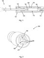
- Fig. 1 is a cross-section schematic drawing of an energy absorption device 100 according to an example embodiment of the invention.
- Fig. 1 shows example components of the device 100 in alignment with each other.
- the embodiment shown in Fig. 1 includes a piston head 115 that moves axially under load internal to an internal cylinder (shock tube) 110.
- the shock tube 110 is positioned internal to a second cylinder (external cylinder) 105 and connected to a component at the far end of the external cylinder, a distal cylinder end 135.
- the shock tube 110 and cylinder end 135 are a close mechanical fit between the outside diameter of the shock tube 110 and the inside diameter of the external cylinder 135, but are able to be rotated through an externally located adjustment component (e.g., adjustment knob) 150.
- an externally located adjustment component e.g., adjustment knob
- the inside diameter of the external cylinder 105 is round, but is interrupted by a flow channel 140 running axially down one side of the device 100.
- This flow channel 140 may be of constant area or may be configured to be variable in size vs. its position on the external cylinder's axis.
- the shock tube 110 can be configured with multiple arrangements of holes (groups of holes) 145, with each group being restricted to an area on the shock tube 110 in approximately the same size as the flow channel 145 on the inside diameter surface of the external cylinder 105.
- Each group of holes 145 may be called an "orifice pattern" and, along with the flow channel 145, determines the effective damping performance of the device 100.
- Multiple orifice patterns may be incorporated into a single shock tube, with each pattern being tuned to deliver optimum performance under different input conditions. A user can select which pattern to activate by rotating the shock tube 100 relative to the external cylinder 105.
- the orifice patterns 145 can be constructed in a spiral configuration, with the configuration being designed in concert with the flow channel 145 in the inside diameter wall of the external cylinder 105. This configuration effectively delivers square wave damping in the device, which a user can adjust in a manner similar to traditional adjustable shock absorbers.
- the ability to combine dashpot, square wave, and progressive wave, and self-compensating damping in a single device 100 is itself unprecedented, as is the ability to deliver sublinear damping force vs. input velocity performance in an adjustable device. It allows a user of the device 100 to make a much simpler sizing calculation and decision, and provides the user with the ability to easily and simply adjust the shock absorber 100 to a specific application, for example, with the turn of an adjustment knob 150. It also reduces product variation in the manufacturing process, providing economy of scale in manufacturing quantities at much lower levels than those afforded by traditional shock absorber models.
- Fig. 2 is a cross-section schematic drawing of an energy absorption device 200 according to an example embodiment of the invention.
- Fig. 2 shows an example flow channel 240 on the inner diameter of the external cylinder 205 in more detail, as well as a shock tube 210 containing three orifice patterns 245.
- the illustrated example embodiment shows that because the flow channel 240 may only align with one of the three orifice patters 245 at a time, only one of the orifice patterns 245 may be active at any given time, allowing the example device 200 shown in Fig. 2 to act as three separate shock absorbers in one device.
- Figs. 3A and 3B are schematic drawings of a shock tube 310 with tapered grooves 320 according to an example embodiment of the invention.
- the example shock tube 310 shown in Figs. 3A and 3B includes on the outside diameter of the shock tube 310 at least one circumferential tapered groove 320.
- the tapered groove(s) 320 at one end is of a certain depth in the shock tube 310 and tapers to a lesser depth at the other end of the groove(s) 320.
- the tapered groove 320 may extend about 350 degrees around the outside diameter of the shock tube 310, and may start at a certain depth at one end and taper to a depth of zero at the other end of the groove 320, about 350 degrees from where the groove 320 started.
- a slot cut axially along the length of the external cylinder interfaces the groove 320 to allow for oil/fluid to flow through the orifices 330, groove 320, and slot (not shown).
- the slot is similar to that of the flow channel 240 shown in Fig. 2 , but may be much narrower.
- the tapered groove 320 presents a resulting projected area and flow path for the oil/fluid of the device to travel.
- the projected area is based on the width and depth of the groove 320 and the width of the slot.
- various orifices 330 of the shock tube may have different start and end points along the groove 320 to achieve variable rotational flow cut off channels.
- the shock tube 310 may include multiple tapered grooves 320 that start and end at differing points around the shock tube 310.
- the example shock 310 tube of Figs. 3A and 3B is suitable for use in an energy absorption device that includes an external cylinder housing member, shock tube 310, piston, and accumulator, where the shock tube 310 is rotatably secured within the external cylinder and has an interior surface, an exterior surface, and a group of inline holes 330 along the long axis of the shock tube 310.
- each hole 330 passes from the interior surface of the shock tube 310 to the exterior surface of the shock tube 310 to allow fluid to pass therethrough.
- the shock tube 310 also has a group of tapered grooves 320, corresponding to the group of inline holes 330, on the exterior surface of the shock tube 310.
- Each tapered groove 320 starts at the location of a corresponding hole 330 and is of a first depth into the exterior surface of the shock tube.
- Each tapered groove 320 ends at another location around the circumference of the shock tube 310 and is of a second depth into the exterior surface of the shock tube 310.
- the second depth of the groove 320 is less than the first depth of the groove 320, and the depth of the groove 320 tapers from the first depth to the second depth.
- the external cylinder has a distal end, a proximal end, an interior wall, and a flow channel formed on the interior wall of the external cylinder (not shown).
- the flow channel substantially extends along the length of the external cylinder and is in fluid communication with the accumulator.
- the piston includes a head portion and a rod portion. The head portion is slidably retained within the shock tube, and the rod portion extends from the head portion through the proximal end of the external cylinder and engages with an external body in motion.
- the accumulator is contained within the external cylinder and collects fluid from the interior of the shock tube when the head portion of the piston moves toward the distal end of the external cylinder.
- Relative rotation between the shock tube 310 and the external cylinder changes which parts of the tapered grooves 320 interface the flow channel to adjustably change the rate of fluid flow out of the shock tube, through the group of inline holes 330, through the tapered grooves 320, through the flow channel, and into the accumulator. Such rotation, thus, changes the dampening of the energy absorption device.
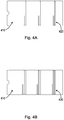
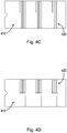
- Figs. 4A-4D are schematic drawings of a shock tube 410 with tapered grooves 420 according to an example embodiment of the invention.
- Figs. 4A-4D show various views of an example shock tube 410 having multiple circumferential tapered grooves 420.
- Figs. 5A and 5B are schematic drawings of example shock tubes 510, 512 with at least one tapered patch 520 or 525, 535 according to example embodiments of the invention.
- the example shock tube 510 shown in Figs. 5A includes on the outside diameter of the shock tube 510 a circumferential tapered patch 520.
- the tapered patch 520 at one end is of a certain depth 522 in the shock tube 510 and tapers to a lesser depth 524 at the other end of the patch 520.
- the tapered patch 520 may extend about 350 degrees around the outside diameter of the shock tube 510, and may start at a certain depth 522 at one end and taper to a depth of zero 524 at the other end of the patch 520, about 350 degrees from where the patch 520 started.
- a slot cut axially along the length of the external cylinder interfaces the patch 520 to allow for oil/fluid to flow through the orifices 530, patch 520, and slot (not shown).
- the slot is similar to that of the flow channel 240 shown in Fig. 2 , but may be much narrower.
- the patch 520 starts at and spans the length of the shock tube's orifice pattern 530. In some embodiments, as shown in Fig.
- a shock tube 512 may include multiple tapered patches 525, 535 that start and end at differing points 523, 526, 532, 534 around the shock tube 512, and the external cylinder may include multiple corresponding slots (not shown).
- the tapered patch 520 presents a resulting projected area and flow path for the oil/fluid of the device to travel.
- the projected area is based on the width and depth of the patch 520 and the width of the slot.
- the example shock tubes 510, 512 of Figs. 5A and 5B are suitable for use in an energy absorption device that includes an external cylinder housing member, shock tube, piston, and accumulator, where the shock tube 510, in the case of the shock tube of Fig. 5A , for example, is rotatably secured within the external cylinder and has an interior surface, an exterior surface, and a group of inline holes 530 along the long axis of the shock tube 510. In such a device, each hole 530 passes from the interior surface of the shock tube 510 to the exterior surface of the shock tube 510 to allow fluid to pass therethrough.
- the shock tube 510 also has a tapered patch 520 on the exterior surface of the shock tube 510.
- the tapered patch 520 starts at the location of the group of inline holes 530 and is of a first depth 522 into the exterior surface of the shock tube 510.
- the tapered patch 520 ends at another location around the circumference of the shock tube 510 and is of a second depth 524 into the exterior surface of the shock tube 510.
- the second depth 524 is less than the first depth 522, and the depth of the tapered patch 520 tapers from the first depth 522 to the second depth 524.
- the external cylinder has a distal end, a proximal end, an interior wall, and a flow channel formed on the interior wall of the external cylinder (not shown).
- the flow channel substantially extends along the length of the external cylinder and is in fluid communication with the accumulator.
- the piston includes a head portion and a rod portion. The head portion is slidably retained within the shock tube, and the rod portion extends from the head portion through the proximal end of the external cylinder and engages with an external body in motion.
- the accumulator is contained within the external cylinder and collects fluid from the interior of the shock tube when the head portion of the piston moves toward the distal end of the external cylinder.
- Relative rotation between the shock tube 510 and the external cylinder changes which part of the tapered patch 520 interfaces the flow channel to adjustably change the rate of fluid flow out of the shock tube, through the group of inline holes 530, through the tapered patch, through the flow channel, and into the accumulator. Such rotation, thus, changes the dampening of the energy absorption device.
- An example advantage of embodiments using the disclosed tapered patch is that machining costs can be reduced. Rather than manufacturing a shock tube with several close tolerance machine cuts, inclusion of the patch allows for a faster, simpler large cut that is less expensive to manufacture.
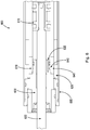
- Fig. 6 is a cross-section schematic drawing of an energy absorption device 600 with a tapered groove (end groove) 640 on a cylinder end 630 used for damping adjustment according to an example embodiment of the invention.
- a groove 640 on a cylinder end 630 can be either in combination with an orifice pattern (not shown) through the shock tube 610 wall, or alone.
- An orifice being through the cylinder end 630 by virtue of its size and flow characteristics, yields unique damping characteristics as compared to an orifice being through the shock tube 610 wall, including dashpot damping and the potential to deliver damping and shock force proportional to a sublinear power of an impact velocity.
- the energy absorption device may include a cylinder end 630 at the proximal end of the external cylinder 605, an end groove 640 on the exterior surface of the cylinder end 630, a first orifice 635 in the cylinder end 630, and a second orifice 645 in the shock tube 610.
- the end groove 640 starts at a first location on the exterior surface of the cylinder end 630 and is of a first depth into the exterior surface of the cylinder end 630.
- the end groove 640 ends at a second location around the circumference of the cylinder end 630 and is of a second depth into the exterior surface of the cylinder end 630.
- the second depth of the end groove 640 is less than the first depth of the end groove 640, and the depth of the end groove 640 tapers from the first depth of the end groove 640 to the second depth of the end groove 640.
- the first orifice 635 (in the cylinder end) is in fluid communication with the interior of the shock tube 610 and the end groove 640, and allows fluid to flow from the interior of the shock tube 610 to the end groove 640 when the head portion 615 of the piston moves toward the proximal end of the external cylinder 605.
- the second orifice 645 (in the shock tube) is in fluid communication with the end groove 640 and the accumulator 625, and allows fluid to flow from the end groove 640 to the accumulator 625 when the head portion 615 of the piston moves toward the proximal end of the external cylinder 605.
- Relative rotation between the shock tube 610 and the external cylinder 605 changes which part of the end groove 640 interfaces the second orifice 645 (in the shock tube) to adjustably change the rate of fluid flow out of the shock tube 610, through the first orifice 635 (in the cylinder end), through the end groove 640, through the second orifice 645 (in the shock tube), and into the accumulator 625.
- Such rotation changes the dampening of the energy absorption device.
- the end groove can be on the interior surface of the shock tube 610, or located in the exterior surface of the shock tube 610.
- the end groove may be located at the opposite end of the device than the accumulator 625 (e.g., at the distal end of the embodiment shown in Fig. 6 ), and in such embodiments, an axial groove may be cut on the outside diameter of the shock tube 610 to provide a flow path to the accumulator area 625.
Landscapes
- Engineering & Computer Science (AREA)
- General Engineering & Computer Science (AREA)
- Mechanical Engineering (AREA)
- Physics & Mathematics (AREA)
- Fluid Mechanics (AREA)
- Fluid-Damping Devices (AREA)
Applications Claiming Priority (5)
| Application Number | Priority Date | Filing Date | Title |
|---|---|---|---|
| US201361755051P | 2013-01-22 | 2013-01-22 | |
| US201361827900P | 2013-05-28 | 2013-05-28 | |
| US201361861115P | 2013-08-01 | 2013-08-01 | |
| US14/159,135 US9133902B2 (en) | 2013-01-22 | 2014-01-20 | Shock absorber with variable damping profile |
| PCT/US2014/012246 WO2014116557A1 (en) | 2013-01-22 | 2014-01-21 | Shock absorber with variable damping profile |
Publications (2)
| Publication Number | Publication Date |
|---|---|
| EP2951459A1 EP2951459A1 (en) | 2015-12-09 |
| EP2951459B1 true EP2951459B1 (en) | 2020-05-06 |
Family
ID=51206862
Family Applications (1)
| Application Number | Title | Priority Date | Filing Date |
|---|---|---|---|
| EP14703695.8A Active EP2951459B1 (en) | 2013-01-22 | 2014-01-21 | Shock absorber with variable damping profile |
Country Status (5)
| Country | Link |
|---|---|
| US (1) | US9133902B2 (enExample) |
| EP (1) | EP2951459B1 (enExample) |
| JP (1) | JP6416123B2 (enExample) |
| CA (1) | CA2898851C (enExample) |
| WO (1) | WO2014116557A1 (enExample) |
Cited By (1)
| Publication number | Priority date | Publication date | Assignee | Title |
|---|---|---|---|---|
| DE102021117898A1 (de) | 2021-07-12 | 2023-01-12 | Stabilus Gmbh | Fluiddämpfer zur Modulierung einer Rückhaltekraft eines Sicherheitsgurtes |
Families Citing this family (24)
| Publication number | Priority date | Publication date | Assignee | Title |
|---|---|---|---|---|
| US8616351B2 (en) | 2009-10-06 | 2013-12-31 | Tenneco Automotive Operating Company Inc. | Damper with digital valve |
| US9217483B2 (en) | 2013-02-28 | 2015-12-22 | Tenneco Automotive Operating Company Inc. | Valve switching controls for adjustable damper |
| US9884533B2 (en) | 2013-02-28 | 2018-02-06 | Tenneco Automotive Operating Company Inc. | Autonomous control damper |
| WO2014134500A1 (en) | 2013-02-28 | 2014-09-04 | Tenneco Automotive Operating Company Inc. | Damper with integrated electronics |
| US9879748B2 (en) | 2013-03-15 | 2018-01-30 | Tenneco Automotive Operating Company Inc. | Two position valve with face seal and pressure relief port |
| EP2971847A4 (en) | 2013-03-15 | 2016-12-21 | Tenneco Automotive Operating Co Inc | BAR GUIDE ASSEMBLY WITH MULTIPLE VALVE ASSEMBLY |
| US9879746B2 (en) | 2013-03-15 | 2018-01-30 | Tenneco Automotive Operating Company Inc. | Rod guide system and method with multiple solenoid valve cartridges and multiple pressure regulated valve assemblies |
| US9163691B2 (en) | 2013-03-15 | 2015-10-20 | Tenneco Automotive Operating Company Inc. | Rod guide arrangement for electronically controlled valve applications |
| JP2016130543A (ja) * | 2015-01-13 | 2016-07-21 | 株式会社ショーワ | 圧力緩衝装置 |
| DE112016000579B4 (de) * | 2015-02-03 | 2024-03-28 | Tenneco Automotive Operating Company Inc. | Sekundäre dämpfungsanordnung für einen stossdämpfer |
| US9822837B2 (en) | 2015-02-06 | 2017-11-21 | Tenneco Automotive Operating Company Inc. | Secondary dampening assembly for shock absorber |
| US9752848B2 (en) * | 2015-03-19 | 2017-09-05 | Kyntec Corporation | Recoil shock absorber for long barrel firearms |
| CN104930017B (zh) * | 2015-06-29 | 2017-01-11 | 中国科学院广州能源研究所 | 一种可调节两端缓冲能量的液压装置 |
| FR3046824A1 (fr) * | 2016-01-18 | 2017-07-21 | Hydraulique Pb | Ralentisseur progressif de fin de course et demarreur progressif de debut de course pour verin hydraulique |
| JP2017172777A (ja) * | 2016-03-25 | 2017-09-28 | 株式会社ショーワ | エアばね構造 |
| US10006739B2 (en) | 2016-06-08 | 2018-06-26 | Outdoor Sport Innovations, Llc | Firearm recoil absorber |
| WO2018124136A1 (ja) * | 2016-12-26 | 2018-07-05 | 日立オートモティブシステムズ株式会社 | シリンダ装置 |
| US10479160B2 (en) | 2017-06-06 | 2019-11-19 | Tenneco Automotive Operating Company Inc. | Damper with printed circuit board carrier |
| US10588233B2 (en) | 2017-06-06 | 2020-03-10 | Tenneco Automotive Operating Company Inc. | Damper with printed circuit board carrier |
| DE102017212021A1 (de) * | 2017-07-13 | 2019-01-17 | Siemens Aktiengesellschaft | Anordnung und Verfahren zum Dämpfen von Schaltbewegungen in Hochspannungsleistungsschaltern |
| US11199237B2 (en) * | 2018-08-08 | 2021-12-14 | Raptor Performance Shocks, LLC | Internal bypass shock absorber |
| EP3809012B1 (en) * | 2019-10-18 | 2025-06-11 | Öhlins Racing AB | Front fork position-dependent damping for bicycles and motorcycles |
| CN110921458B (zh) * | 2019-12-16 | 2021-08-20 | 安徽金晥泵业科技股份有限公司 | 一种点刹式液压缓冲器 |
| US20230356558A1 (en) * | 2022-05-04 | 2023-11-09 | Fox Factory, Inc. | Shock assembly with by-pass and hydraulic adjust |
Citations (6)
| Publication number | Priority date | Publication date | Assignee | Title |
|---|---|---|---|---|
| US3840097A (en) * | 1973-01-22 | 1974-10-08 | Hennells W Co Inc | Adjustable shock absorber |
| US4057236A (en) * | 1975-08-29 | 1977-11-08 | Hennells Ransom J | Energy absorber |
| US4059175A (en) * | 1975-05-06 | 1977-11-22 | Dressell Jr Richard G | Linear force shock absorber |
| EP1266149A1 (fr) * | 2000-03-24 | 2002-12-18 | Etablissements Jean Perret | Amortisseur hydraulique avec reglage du type d'amortissement |
| US20040094376A1 (en) * | 2002-11-15 | 2004-05-20 | Simon Van Wonderen | Adjustable shock absorber |
| US6974002B2 (en) * | 2003-03-20 | 2005-12-13 | Ace Controls, Inc. | Adjustable shock absorber |
Family Cites Families (7)
| Publication number | Priority date | Publication date | Assignee | Title |
|---|---|---|---|---|
| JPS4842267A (enExample) * | 1971-10-06 | 1973-06-20 | ||
| US4071122A (en) * | 1976-04-21 | 1978-01-31 | Efdyn Corporation | Adjustable shock absorber |
| JPS5528191U (enExample) * | 1978-08-15 | 1980-02-23 | ||
| JPS6131558Y2 (enExample) * | 1981-04-10 | 1986-09-13 | ||
| US4690255A (en) * | 1986-03-10 | 1987-09-01 | Enertrols, Inc. | Compact shock absorber |
| US5598904A (en) * | 1995-06-05 | 1997-02-04 | Enidine, Inc. | Adjustable energy absorption device |
| US6065573A (en) * | 1998-09-04 | 2000-05-23 | Enidine, Inc. | Adjustable energy absorption device with break-off adjustment knob |
-
2014
- 2014-01-20 US US14/159,135 patent/US9133902B2/en active Active
- 2014-01-21 CA CA2898851A patent/CA2898851C/en active Active
- 2014-01-21 WO PCT/US2014/012246 patent/WO2014116557A1/en not_active Ceased
- 2014-01-21 JP JP2015555209A patent/JP6416123B2/ja active Active
- 2014-01-21 EP EP14703695.8A patent/EP2951459B1/en active Active
Patent Citations (6)
| Publication number | Priority date | Publication date | Assignee | Title |
|---|---|---|---|---|
| US3840097A (en) * | 1973-01-22 | 1974-10-08 | Hennells W Co Inc | Adjustable shock absorber |
| US4059175A (en) * | 1975-05-06 | 1977-11-22 | Dressell Jr Richard G | Linear force shock absorber |
| US4057236A (en) * | 1975-08-29 | 1977-11-08 | Hennells Ransom J | Energy absorber |
| EP1266149A1 (fr) * | 2000-03-24 | 2002-12-18 | Etablissements Jean Perret | Amortisseur hydraulique avec reglage du type d'amortissement |
| US20040094376A1 (en) * | 2002-11-15 | 2004-05-20 | Simon Van Wonderen | Adjustable shock absorber |
| US6974002B2 (en) * | 2003-03-20 | 2005-12-13 | Ace Controls, Inc. | Adjustable shock absorber |
Cited By (4)
| Publication number | Priority date | Publication date | Assignee | Title |
|---|---|---|---|---|
| DE102021117898A1 (de) | 2021-07-12 | 2023-01-12 | Stabilus Gmbh | Fluiddämpfer zur Modulierung einer Rückhaltekraft eines Sicherheitsgurtes |
| EP4275969A3 (de) * | 2021-07-12 | 2024-02-07 | STABILUS GmbH | Fluiddämpfer zur modulierung einer rückhaltekraft eines sicherheitsgurtes |
| US12139098B2 (en) | 2021-07-12 | 2024-11-12 | Stabilus Gmbh | Fluid damper for modulating a retaining force of a seat belt |
| EP4122779B1 (de) * | 2021-07-12 | 2025-02-26 | STABILUS GmbH | Fluiddämpfer zur modulierung einer rückhaltekraft eines sicherheitsgurtes |
Also Published As
| Publication number | Publication date |
|---|---|
| EP2951459A1 (en) | 2015-12-09 |
| US9133902B2 (en) | 2015-09-15 |
| CA2898851C (en) | 2020-04-14 |
| CA2898851A1 (en) | 2014-07-31 |
| JP2016504551A (ja) | 2016-02-12 |
| JP6416123B2 (ja) | 2018-10-31 |
| US20140202808A1 (en) | 2014-07-24 |
| WO2014116557A1 (en) | 2014-07-31 |
Similar Documents
| Publication | Publication Date | Title |
|---|---|---|
| EP2951459B1 (en) | Shock absorber with variable damping profile | |
| EP3176464B1 (en) | Hydraulic suspension damper with a hydro-mechanical stroke stop | |
| US8262062B2 (en) | Rotary valve | |
| JP4517373B2 (ja) | ショックアブソーバ | |
| US10597112B2 (en) | Suspension system | |
| AU2007336155B2 (en) | Percussion device | |
| US10618593B2 (en) | Suspension system | |
| JP2016504551A5 (enExample) | ||
| KR100877613B1 (ko) | 완충기 | |
| EP0273038B1 (en) | Compact shock absorber | |
| JP4129936B2 (ja) | 調圧弁及び油圧制振装置 | |
| WO2012173550A1 (en) | Device for damping of a piston inside a cylinder housing | |
| JP2015121250A (ja) | ツインピストン・ダンパー | |
| JP6198926B1 (ja) | 油圧緩衝器 | |
| US20090008196A1 (en) | Multistage Adjusting Device | |
| JP4884782B2 (ja) | ショック・アブソーバ | |
| US10288142B2 (en) | Shock absorber | |
| JP4058298B2 (ja) | 油圧緩衝器 | |
| JPH0727166A (ja) | ショックアブソーバの減衰力調整装置 | |
| KR20140080177A (ko) | 완충기 | |
| JPH0324912Y2 (enExample) | ||
| JPH08270785A (ja) | 変速機の操作装置 | |
| JPS6210507Y2 (enExample) | ||
| JP6626336B2 (ja) | ショックアブソーバ | |
| CN108980257B (zh) | 缓冲器 |
Legal Events
| Date | Code | Title | Description |
|---|---|---|---|
| PUAI | Public reference made under article 153(3) epc to a published international application that has entered the european phase |
Free format text: ORIGINAL CODE: 0009012 |
|
| 17P | Request for examination filed |
Effective date: 20150817 |
|
| AK | Designated contracting states |
Kind code of ref document: A1 Designated state(s): AL AT BE BG CH CY CZ DE DK EE ES FI FR GB GR HR HU IE IS IT LI LT LU LV MC MK MT NL NO PL PT RO RS SE SI SK SM TR |
|
| AX | Request for extension of the european patent |
Extension state: BA ME |
|
| RIN1 | Information on inventor provided before grant (corrected) |
Inventor name: SPYCHE, GERALD, J. Inventor name: JOPP, ALLAN, J. Inventor name: TAYLOR, SCOTT, J. Inventor name: SCHOEN, JOSEPH |
|
| DAX | Request for extension of the european patent (deleted) | ||
| STAA | Information on the status of an ep patent application or granted ep patent |
Free format text: STATUS: EXAMINATION IS IN PROGRESS |
|
| 17Q | First examination report despatched |
Effective date: 20180712 |
|
| REG | Reference to a national code |
Ref country code: DE Ref legal event code: R079 Ref document number: 602014064876 Country of ref document: DE Free format text: PREVIOUS MAIN CLASS: F16F0009346000 Ipc: F16F0009512000 |
|
| RIC1 | Information provided on ipc code assigned before grant |
Ipc: F16F 9/512 20060101AFI20191017BHEP |
|
| GRAP | Despatch of communication of intention to grant a patent |
Free format text: ORIGINAL CODE: EPIDOSNIGR1 |
|
| STAA | Information on the status of an ep patent application or granted ep patent |
Free format text: STATUS: GRANT OF PATENT IS INTENDED |
|
| INTG | Intention to grant announced |
Effective date: 20191210 |
|
| RIN1 | Information on inventor provided before grant (corrected) |
Inventor name: JOPP, ALLAN, J. Inventor name: TAYLOR, SCOTT, J. Inventor name: SPYCHE, GERALD, J. Inventor name: SCHOEN, JOSEPH |
|
| GRAS | Grant fee paid |
Free format text: ORIGINAL CODE: EPIDOSNIGR3 |
|
| GRAA | (expected) grant |
Free format text: ORIGINAL CODE: 0009210 |
|
| STAA | Information on the status of an ep patent application or granted ep patent |
Free format text: STATUS: THE PATENT HAS BEEN GRANTED |
|
| AK | Designated contracting states |
Kind code of ref document: B1 Designated state(s): AL AT BE BG CH CY CZ DE DK EE ES FI FR GB GR HR HU IE IS IT LI LT LU LV MC MK MT NL NO PL PT RO RS SE SI SK SM TR |
|
| REG | Reference to a national code |
Ref country code: GB Ref legal event code: FG4D |
|
| REG | Reference to a national code |
Ref country code: AT Ref legal event code: REF Ref document number: 1267243 Country of ref document: AT Kind code of ref document: T Effective date: 20200515 Ref country code: CH Ref legal event code: EP |
|
| REG | Reference to a national code |
Ref country code: IE Ref legal event code: FG4D |
|
| REG | Reference to a national code |
Ref country code: DE Ref legal event code: R096 Ref document number: 602014064876 Country of ref document: DE |
|
| REG | Reference to a national code |
Ref country code: LT Ref legal event code: MG4D |
|
| REG | Reference to a national code |
Ref country code: NL Ref legal event code: MP Effective date: 20200506 |
|
| PG25 | Lapsed in a contracting state [announced via postgrant information from national office to epo] |
Ref country code: GR Free format text: LAPSE BECAUSE OF FAILURE TO SUBMIT A TRANSLATION OF THE DESCRIPTION OR TO PAY THE FEE WITHIN THE PRESCRIBED TIME-LIMIT Effective date: 20200807 Ref country code: NO Free format text: LAPSE BECAUSE OF FAILURE TO SUBMIT A TRANSLATION OF THE DESCRIPTION OR TO PAY THE FEE WITHIN THE PRESCRIBED TIME-LIMIT Effective date: 20200806 Ref country code: LT Free format text: LAPSE BECAUSE OF FAILURE TO SUBMIT A TRANSLATION OF THE DESCRIPTION OR TO PAY THE FEE WITHIN THE PRESCRIBED TIME-LIMIT Effective date: 20200506 Ref country code: SE Free format text: LAPSE BECAUSE OF FAILURE TO SUBMIT A TRANSLATION OF THE DESCRIPTION OR TO PAY THE FEE WITHIN THE PRESCRIBED TIME-LIMIT Effective date: 20200506 Ref country code: FI Free format text: LAPSE BECAUSE OF FAILURE TO SUBMIT A TRANSLATION OF THE DESCRIPTION OR TO PAY THE FEE WITHIN THE PRESCRIBED TIME-LIMIT Effective date: 20200506 Ref country code: IS Free format text: LAPSE BECAUSE OF FAILURE TO SUBMIT A TRANSLATION OF THE DESCRIPTION OR TO PAY THE FEE WITHIN THE PRESCRIBED TIME-LIMIT Effective date: 20200906 Ref country code: PT Free format text: LAPSE BECAUSE OF FAILURE TO SUBMIT A TRANSLATION OF THE DESCRIPTION OR TO PAY THE FEE WITHIN THE PRESCRIBED TIME-LIMIT Effective date: 20200907 |
|
| PG25 | Lapsed in a contracting state [announced via postgrant information from national office to epo] |
Ref country code: HR Free format text: LAPSE BECAUSE OF FAILURE TO SUBMIT A TRANSLATION OF THE DESCRIPTION OR TO PAY THE FEE WITHIN THE PRESCRIBED TIME-LIMIT Effective date: 20200506 Ref country code: RS Free format text: LAPSE BECAUSE OF FAILURE TO SUBMIT A TRANSLATION OF THE DESCRIPTION OR TO PAY THE FEE WITHIN THE PRESCRIBED TIME-LIMIT Effective date: 20200506 Ref country code: LV Free format text: LAPSE BECAUSE OF FAILURE TO SUBMIT A TRANSLATION OF THE DESCRIPTION OR TO PAY THE FEE WITHIN THE PRESCRIBED TIME-LIMIT Effective date: 20200506 Ref country code: BG Free format text: LAPSE BECAUSE OF FAILURE TO SUBMIT A TRANSLATION OF THE DESCRIPTION OR TO PAY THE FEE WITHIN THE PRESCRIBED TIME-LIMIT Effective date: 20200806 |
|
| REG | Reference to a national code |
Ref country code: AT Ref legal event code: MK05 Ref document number: 1267243 Country of ref document: AT Kind code of ref document: T Effective date: 20200506 |
|
| PG25 | Lapsed in a contracting state [announced via postgrant information from national office to epo] |
Ref country code: NL Free format text: LAPSE BECAUSE OF FAILURE TO SUBMIT A TRANSLATION OF THE DESCRIPTION OR TO PAY THE FEE WITHIN THE PRESCRIBED TIME-LIMIT Effective date: 20200506 Ref country code: AL Free format text: LAPSE BECAUSE OF FAILURE TO SUBMIT A TRANSLATION OF THE DESCRIPTION OR TO PAY THE FEE WITHIN THE PRESCRIBED TIME-LIMIT Effective date: 20200506 |
|
| PG25 | Lapsed in a contracting state [announced via postgrant information from national office to epo] |
Ref country code: IT Free format text: LAPSE BECAUSE OF FAILURE TO SUBMIT A TRANSLATION OF THE DESCRIPTION OR TO PAY THE FEE WITHIN THE PRESCRIBED TIME-LIMIT Effective date: 20200506 Ref country code: CZ Free format text: LAPSE BECAUSE OF FAILURE TO SUBMIT A TRANSLATION OF THE DESCRIPTION OR TO PAY THE FEE WITHIN THE PRESCRIBED TIME-LIMIT Effective date: 20200506 Ref country code: RO Free format text: LAPSE BECAUSE OF FAILURE TO SUBMIT A TRANSLATION OF THE DESCRIPTION OR TO PAY THE FEE WITHIN THE PRESCRIBED TIME-LIMIT Effective date: 20200506 Ref country code: SM Free format text: LAPSE BECAUSE OF FAILURE TO SUBMIT A TRANSLATION OF THE DESCRIPTION OR TO PAY THE FEE WITHIN THE PRESCRIBED TIME-LIMIT Effective date: 20200506 Ref country code: ES Free format text: LAPSE BECAUSE OF FAILURE TO SUBMIT A TRANSLATION OF THE DESCRIPTION OR TO PAY THE FEE WITHIN THE PRESCRIBED TIME-LIMIT Effective date: 20200506 Ref country code: DK Free format text: LAPSE BECAUSE OF FAILURE TO SUBMIT A TRANSLATION OF THE DESCRIPTION OR TO PAY THE FEE WITHIN THE PRESCRIBED TIME-LIMIT Effective date: 20200506 Ref country code: AT Free format text: LAPSE BECAUSE OF FAILURE TO SUBMIT A TRANSLATION OF THE DESCRIPTION OR TO PAY THE FEE WITHIN THE PRESCRIBED TIME-LIMIT Effective date: 20200506 Ref country code: EE Free format text: LAPSE BECAUSE OF FAILURE TO SUBMIT A TRANSLATION OF THE DESCRIPTION OR TO PAY THE FEE WITHIN THE PRESCRIBED TIME-LIMIT Effective date: 20200506 |
|
| REG | Reference to a national code |
Ref country code: DE Ref legal event code: R097 Ref document number: 602014064876 Country of ref document: DE |
|
| PG25 | Lapsed in a contracting state [announced via postgrant information from national office to epo] |
Ref country code: SK Free format text: LAPSE BECAUSE OF FAILURE TO SUBMIT A TRANSLATION OF THE DESCRIPTION OR TO PAY THE FEE WITHIN THE PRESCRIBED TIME-LIMIT Effective date: 20200506 Ref country code: PL Free format text: LAPSE BECAUSE OF FAILURE TO SUBMIT A TRANSLATION OF THE DESCRIPTION OR TO PAY THE FEE WITHIN THE PRESCRIBED TIME-LIMIT Effective date: 20200506 |
|
| PLBE | No opposition filed within time limit |
Free format text: ORIGINAL CODE: 0009261 |
|
| STAA | Information on the status of an ep patent application or granted ep patent |
Free format text: STATUS: NO OPPOSITION FILED WITHIN TIME LIMIT |
|
| 26N | No opposition filed |
Effective date: 20210209 |
|
| PG25 | Lapsed in a contracting state [announced via postgrant information from national office to epo] |
Ref country code: SI Free format text: LAPSE BECAUSE OF FAILURE TO SUBMIT A TRANSLATION OF THE DESCRIPTION OR TO PAY THE FEE WITHIN THE PRESCRIBED TIME-LIMIT Effective date: 20200506 |
|
| PG25 | Lapsed in a contracting state [announced via postgrant information from national office to epo] |
Ref country code: MC Free format text: LAPSE BECAUSE OF FAILURE TO SUBMIT A TRANSLATION OF THE DESCRIPTION OR TO PAY THE FEE WITHIN THE PRESCRIBED TIME-LIMIT Effective date: 20200506 |
|
| REG | Reference to a national code |
Ref country code: CH Ref legal event code: PL |
|
| PG25 | Lapsed in a contracting state [announced via postgrant information from national office to epo] |
Ref country code: LU Free format text: LAPSE BECAUSE OF NON-PAYMENT OF DUE FEES Effective date: 20210121 |
|
| REG | Reference to a national code |
Ref country code: BE Ref legal event code: MM Effective date: 20210131 |
|
| PG25 | Lapsed in a contracting state [announced via postgrant information from national office to epo] |
Ref country code: FR Free format text: LAPSE BECAUSE OF NON-PAYMENT OF DUE FEES Effective date: 20210131 |
|
| PG25 | Lapsed in a contracting state [announced via postgrant information from national office to epo] |
Ref country code: LI Free format text: LAPSE BECAUSE OF NON-PAYMENT OF DUE FEES Effective date: 20210131 Ref country code: CH Free format text: LAPSE BECAUSE OF NON-PAYMENT OF DUE FEES Effective date: 20210131 |
|
| PG25 | Lapsed in a contracting state [announced via postgrant information from national office to epo] |
Ref country code: IE Free format text: LAPSE BECAUSE OF NON-PAYMENT OF DUE FEES Effective date: 20210121 |
|
| PG25 | Lapsed in a contracting state [announced via postgrant information from national office to epo] |
Ref country code: BE Free format text: LAPSE BECAUSE OF NON-PAYMENT OF DUE FEES Effective date: 20210131 |
|
| PG25 | Lapsed in a contracting state [announced via postgrant information from national office to epo] |
Ref country code: HU Free format text: LAPSE BECAUSE OF FAILURE TO SUBMIT A TRANSLATION OF THE DESCRIPTION OR TO PAY THE FEE WITHIN THE PRESCRIBED TIME-LIMIT; INVALID AB INITIO Effective date: 20140121 |
|
| PG25 | Lapsed in a contracting state [announced via postgrant information from national office to epo] |
Ref country code: CY Free format text: LAPSE BECAUSE OF FAILURE TO SUBMIT A TRANSLATION OF THE DESCRIPTION OR TO PAY THE FEE WITHIN THE PRESCRIBED TIME-LIMIT Effective date: 20200506 |
|
| P01 | Opt-out of the competence of the unified patent court (upc) registered |
Effective date: 20230529 |
|
| PG25 | Lapsed in a contracting state [announced via postgrant information from national office to epo] |
Ref country code: MK Free format text: LAPSE BECAUSE OF FAILURE TO SUBMIT A TRANSLATION OF THE DESCRIPTION OR TO PAY THE FEE WITHIN THE PRESCRIBED TIME-LIMIT Effective date: 20200506 |
|
| PG25 | Lapsed in a contracting state [announced via postgrant information from national office to epo] |
Ref country code: MT Free format text: LAPSE BECAUSE OF FAILURE TO SUBMIT A TRANSLATION OF THE DESCRIPTION OR TO PAY THE FEE WITHIN THE PRESCRIBED TIME-LIMIT Effective date: 20200506 |
|
| PG25 | Lapsed in a contracting state [announced via postgrant information from national office to epo] |
Ref country code: TR Free format text: LAPSE BECAUSE OF FAILURE TO SUBMIT A TRANSLATION OF THE DESCRIPTION OR TO PAY THE FEE WITHIN THE PRESCRIBED TIME-LIMIT Effective date: 20200506 |
|
| PGFP | Annual fee paid to national office [announced via postgrant information from national office to epo] |
Ref country code: GB Payment date: 20260112 Year of fee payment: 13 |
|
| PGFP | Annual fee paid to national office [announced via postgrant information from national office to epo] |
Ref country code: DE Payment date: 20260114 Year of fee payment: 13 |