EP2950864B1 - Atemgerät - Google Patents
Atemgerät Download PDFInfo
- Publication number
- EP2950864B1 EP2950864B1 EP14746612.2A EP14746612A EP2950864B1 EP 2950864 B1 EP2950864 B1 EP 2950864B1 EP 14746612 A EP14746612 A EP 14746612A EP 2950864 B1 EP2950864 B1 EP 2950864B1
- Authority
- EP
- European Patent Office
- Prior art keywords
- foam
- cushion
- clip
- foam cushion
- mask
- Prior art date
- Legal status (The legal status is an assumption and is not a legal conclusion. Google has not performed a legal analysis and makes no representation as to the accuracy of the status listed.)
- Active
Links
- 230000000241 respiratory effect Effects 0.000 title claims description 35
- 239000006260 foam Substances 0.000 claims description 563
- 230000009975 flexible effect Effects 0.000 claims description 244
- 238000007789 sealing Methods 0.000 claims description 95
- 239000000463 material Substances 0.000 claims description 72
- 230000006835 compression Effects 0.000 claims description 50
- 238000007906 compression Methods 0.000 claims description 50
- 230000002093 peripheral effect Effects 0.000 claims description 46
- 238000011282 treatment Methods 0.000 claims description 44
- 230000008878 coupling Effects 0.000 claims description 42
- 238000010168 coupling process Methods 0.000 claims description 42
- 238000005859 coupling reaction Methods 0.000 claims description 42
- 230000035699 permeability Effects 0.000 claims description 30
- 229920001296 polysiloxane Polymers 0.000 claims description 30
- 230000000694 effects Effects 0.000 claims description 26
- 230000008093 supporting effect Effects 0.000 claims description 26
- 210000002345 respiratory system Anatomy 0.000 claims description 12
- 230000000994 depressogenic effect Effects 0.000 claims description 11
- 238000007373 indentation Methods 0.000 claims description 11
- 230000004044 response Effects 0.000 claims description 8
- 210000000216 zygoma Anatomy 0.000 claims description 7
- 238000004891 communication Methods 0.000 claims description 5
- 210000001331 nose Anatomy 0.000 description 120
- 210000000214 mouth Anatomy 0.000 description 117
- 238000005516 engineering process Methods 0.000 description 108
- 210000000088 lip Anatomy 0.000 description 75
- 239000003570 air Substances 0.000 description 69
- 239000010410 layer Substances 0.000 description 34
- 238000000034 method Methods 0.000 description 33
- 230000001815 facial effect Effects 0.000 description 31
- 239000007789 gas Substances 0.000 description 28
- 238000006243 chemical reaction Methods 0.000 description 25
- 238000012360 testing method Methods 0.000 description 17
- 238000002560 therapeutic procedure Methods 0.000 description 17
- 210000000845 cartilage Anatomy 0.000 description 16
- 230000001965 increasing effect Effects 0.000 description 16
- 230000033001 locomotion Effects 0.000 description 15
- 229920002725 thermoplastic elastomer Polymers 0.000 description 15
- 239000012528 membrane Substances 0.000 description 14
- 238000012384 transportation and delivery Methods 0.000 description 14
- NOQGZXFMHARMLW-UHFFFAOYSA-N Daminozide Chemical compound CN(C)NC(=O)CCC(O)=O NOQGZXFMHARMLW-UHFFFAOYSA-N 0.000 description 13
- 238000013461 design Methods 0.000 description 13
- 230000007246 mechanism Effects 0.000 description 13
- CURLTUGMZLYLDI-UHFFFAOYSA-N Carbon dioxide Chemical compound O=C=O CURLTUGMZLYLDI-UHFFFAOYSA-N 0.000 description 12
- 230000008859 change Effects 0.000 description 11
- 230000000712 assembly Effects 0.000 description 10
- 238000000429 assembly Methods 0.000 description 10
- 210000003128 head Anatomy 0.000 description 10
- 210000003928 nasal cavity Anatomy 0.000 description 10
- 239000013598 vector Substances 0.000 description 10
- 238000009423 ventilation Methods 0.000 description 10
- 210000000988 bone and bone Anatomy 0.000 description 9
- 238000005520 cutting process Methods 0.000 description 9
- 210000004072 lung Anatomy 0.000 description 9
- 208000023504 respiratory system disease Diseases 0.000 description 9
- 229920002379 silicone rubber Polymers 0.000 description 9
- 239000004433 Thermoplastic polyurethane Substances 0.000 description 8
- 239000000853 adhesive Substances 0.000 description 8
- 230000001070 adhesive effect Effects 0.000 description 8
- 210000002050 maxilla Anatomy 0.000 description 8
- 210000003205 muscle Anatomy 0.000 description 8
- 229920002803 thermoplastic polyurethane Polymers 0.000 description 8
- 241000083547 Columella Species 0.000 description 7
- 241000826860 Trapezium Species 0.000 description 7
- 210000003484 anatomy Anatomy 0.000 description 7
- QVGXLLKOCUKJST-UHFFFAOYSA-N atomic oxygen Chemical compound [O] QVGXLLKOCUKJST-UHFFFAOYSA-N 0.000 description 7
- 238000005452 bending Methods 0.000 description 7
- 229910002092 carbon dioxide Inorganic materials 0.000 description 7
- 239000001569 carbon dioxide Substances 0.000 description 7
- 208000037265 diseases, disorders, signs and symptoms Diseases 0.000 description 7
- 230000001976 improved effect Effects 0.000 description 7
- 229910052760 oxygen Inorganic materials 0.000 description 7
- 239000001301 oxygen Substances 0.000 description 7
- 230000008569 process Effects 0.000 description 7
- 230000002829 reductive effect Effects 0.000 description 7
- 230000029058 respiratory gaseous exchange Effects 0.000 description 7
- 210000000614 rib Anatomy 0.000 description 7
- 210000002105 tongue Anatomy 0.000 description 7
- 206010003497 Asphyxia Diseases 0.000 description 6
- 230000009471 action Effects 0.000 description 6
- 230000000875 corresponding effect Effects 0.000 description 6
- 208000035475 disorder Diseases 0.000 description 6
- 210000001061 forehead Anatomy 0.000 description 6
- 230000006870 function Effects 0.000 description 6
- 210000001847 jaw Anatomy 0.000 description 6
- 230000014759 maintenance of location Effects 0.000 description 6
- 210000004373 mandible Anatomy 0.000 description 6
- 238000004519 manufacturing process Methods 0.000 description 6
- 230000004048 modification Effects 0.000 description 6
- 238000012986 modification Methods 0.000 description 6
- 210000000537 nasal bone Anatomy 0.000 description 6
- 208000018360 neuromuscular disease Diseases 0.000 description 6
- 210000003800 pharynx Anatomy 0.000 description 6
- TVLSRXXIMLFWEO-UHFFFAOYSA-N prochloraz Chemical compound C1=CN=CN1C(=O)N(CCC)CCOC1=C(Cl)C=C(Cl)C=C1Cl TVLSRXXIMLFWEO-UHFFFAOYSA-N 0.000 description 6
- 239000000523 sample Substances 0.000 description 6
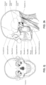
- 210000003625 skull Anatomy 0.000 description 6
- 210000004872 soft tissue Anatomy 0.000 description 6
- 230000003019 stabilising effect Effects 0.000 description 6
- 210000003437 trachea Anatomy 0.000 description 6
- 206010008501 Cheyne-Stokes respiration Diseases 0.000 description 5
- 208000006545 Chronic Obstructive Pulmonary Disease Diseases 0.000 description 5
- 239000004944 Liquid Silicone Rubber Substances 0.000 description 5
- 208000030984 MIRAGE syndrome Diseases 0.000 description 5
- 208000004756 Respiratory Insufficiency Diseases 0.000 description 5
- 230000008901 benefit Effects 0.000 description 5
- 210000003123 bronchiole Anatomy 0.000 description 5
- 210000001508 eye Anatomy 0.000 description 5
- 238000001746 injection moulding Methods 0.000 description 5
- 210000000867 larynx Anatomy 0.000 description 5
- 238000005259 measurement Methods 0.000 description 5
- 238000000465 moulding Methods 0.000 description 5
- 201000004193 respiratory failure Diseases 0.000 description 5
- 230000007704 transition Effects 0.000 description 5
- 206010013975 Dyspnoeas Diseases 0.000 description 4
- 210000000621 bronchi Anatomy 0.000 description 4
- 238000004140 cleaning Methods 0.000 description 4
- 230000000295 complement effect Effects 0.000 description 4
- 229920001971 elastomer Polymers 0.000 description 4
- 239000006261 foam material Substances 0.000 description 4
- 210000002454 frontal bone Anatomy 0.000 description 4
- 238000003780 insertion Methods 0.000 description 4
- 230000037431 insertion Effects 0.000 description 4
- 230000002265 prevention Effects 0.000 description 4
- 230000009467 reduction Effects 0.000 description 4
- 238000002644 respiratory therapy Methods 0.000 description 4
- 208000024891 symptom Diseases 0.000 description 4
- 238000003856 thermoforming Methods 0.000 description 4
- 238000003466 welding Methods 0.000 description 4
- 206010019233 Headaches Diseases 0.000 description 3
- 230000009286 beneficial effect Effects 0.000 description 3
- 239000002131 composite material Substances 0.000 description 3
- 230000007423 decrease Effects 0.000 description 3
- 230000006735 deficit Effects 0.000 description 3
- 230000001419 dependent effect Effects 0.000 description 3
- 230000000881 depressing effect Effects 0.000 description 3
- 238000006073 displacement reaction Methods 0.000 description 3
- 239000013013 elastic material Substances 0.000 description 3
- 230000014509 gene expression Effects 0.000 description 3
- 239000003292 glue Substances 0.000 description 3
- 231100000869 headache Toxicity 0.000 description 3
- 210000003026 hypopharynx Anatomy 0.000 description 3
- 230000003340 mental effect Effects 0.000 description 3
- 210000002184 nasal cartilage Anatomy 0.000 description 3
- 210000000492 nasalseptum Anatomy 0.000 description 3
- 210000001989 nasopharynx Anatomy 0.000 description 3
- 208000001797 obstructive sleep apnea Diseases 0.000 description 3
- 229920002635 polyurethane Polymers 0.000 description 3
- 239000004814 polyurethane Substances 0.000 description 3
- 230000000750 progressive effect Effects 0.000 description 3
- 230000003252 repetitive effect Effects 0.000 description 3
- 230000000717 retained effect Effects 0.000 description 3
- 238000005096 rolling process Methods 0.000 description 3
- 239000005060 rubber Substances 0.000 description 3
- 210000001584 soft palate Anatomy 0.000 description 3
- 239000003351 stiffener Substances 0.000 description 3
- 210000000115 thoracic cavity Anatomy 0.000 description 3
- 210000001260 vocal cord Anatomy 0.000 description 3
- 208000007590 Disorders of Excessive Somnolence Diseases 0.000 description 2
- 206010013801 Duchenne Muscular Dystrophy Diseases 0.000 description 2
- XUIMIQQOPSSXEZ-UHFFFAOYSA-N Silicon Chemical compound [Si] XUIMIQQOPSSXEZ-UHFFFAOYSA-N 0.000 description 2
- 206010041349 Somnolence Diseases 0.000 description 2
- 206010067775 Upper airway obstruction Diseases 0.000 description 2
- 239000002390 adhesive tape Substances 0.000 description 2
- 230000002411 adverse Effects 0.000 description 2
- 206010002026 amyotrophic lateral sclerosis Diseases 0.000 description 2
- 238000000418 atomic force spectrum Methods 0.000 description 2
- 230000015572 biosynthetic process Effects 0.000 description 2
- IISBACLAFKSPIT-UHFFFAOYSA-N bisphenol A Chemical compound C=1C=C(O)C=CC=1C(C)(C)C1=CC=C(O)C=C1 IISBACLAFKSPIT-UHFFFAOYSA-N 0.000 description 2
- 239000008280 blood Substances 0.000 description 2
- 210000004369 blood Anatomy 0.000 description 2
- 238000007664 blowing Methods 0.000 description 2
- 210000000038 chest Anatomy 0.000 description 2
- 230000001684 chronic effect Effects 0.000 description 2
- 238000011513 continuous positive airway pressure therapy Methods 0.000 description 2
- 230000003247 decreasing effect Effects 0.000 description 2
- 230000007547 defect Effects 0.000 description 2
- 238000001514 detection method Methods 0.000 description 2
- 238000003745 diagnosis Methods 0.000 description 2
- 238000009826 distribution Methods 0.000 description 2
- 230000002708 enhancing effect Effects 0.000 description 2
- 210000003414 extremity Anatomy 0.000 description 2
- 235000013305 food Nutrition 0.000 description 2
- 210000002532 foramen magnum Anatomy 0.000 description 2
- 238000005755 formation reaction Methods 0.000 description 2
- 238000000227 grinding Methods 0.000 description 2
- 210000002216 heart Anatomy 0.000 description 2
- 230000003993 interaction Effects 0.000 description 2
- 238000005304 joining Methods 0.000 description 2
- 238000003475 lamination Methods 0.000 description 2
- 230000000670 limiting effect Effects 0.000 description 2
- 238000011068 loading method Methods 0.000 description 2
- 239000000203 mixture Substances 0.000 description 2
- 230000001473 noxious effect Effects 0.000 description 2
- 210000000103 occipital bone Anatomy 0.000 description 2
- 210000003300 oropharynx Anatomy 0.000 description 2
- 210000003455 parietal bone Anatomy 0.000 description 2
- 230000036961 partial effect Effects 0.000 description 2
- 230000007170 pathology Effects 0.000 description 2
- 230000008447 perception Effects 0.000 description 2
- 231100000614 poison Toxicity 0.000 description 2
- 230000007096 poisonous effect Effects 0.000 description 2
- 239000004417 polycarbonate Substances 0.000 description 2
- 229920000515 polycarbonate Polymers 0.000 description 2
- 229920000642 polymer Polymers 0.000 description 2
- -1 polypropylene Polymers 0.000 description 2
- 208000037821 progressive disease Diseases 0.000 description 2
- 229910052710 silicon Inorganic materials 0.000 description 2
- 239000010703 silicon Substances 0.000 description 2
- 238000004513 sizing Methods 0.000 description 2
- 230000000087 stabilizing effect Effects 0.000 description 2
- 230000000153 supplemental effect Effects 0.000 description 2
- 210000003582 temporal bone Anatomy 0.000 description 2
- 230000002123 temporal effect Effects 0.000 description 2
- 210000000779 thoracic wall Anatomy 0.000 description 2
- 210000001944 turbinate Anatomy 0.000 description 2
- ORILYTVJVMAKLC-UHFFFAOYSA-N Adamantane Natural products C1C(C2)CC3CC1CC2C3 ORILYTVJVMAKLC-UHFFFAOYSA-N 0.000 description 1
- 241000750142 Auricula Species 0.000 description 1
- 206010006458 Bronchitis chronic Diseases 0.000 description 1
- BVKZGUZCCUSVTD-UHFFFAOYSA-L Carbonate Chemical compound [O-]C([O-])=O BVKZGUZCCUSVTD-UHFFFAOYSA-L 0.000 description 1
- 208000024172 Cardiovascular disease Diseases 0.000 description 1
- 206010011224 Cough Diseases 0.000 description 1
- 240000004244 Cucurbita moschata Species 0.000 description 1
- 235000009854 Cucurbita moschata Nutrition 0.000 description 1
- 235000009852 Cucurbita pepo Nutrition 0.000 description 1
- 208000019505 Deglutition disease Diseases 0.000 description 1
- 208000000059 Dyspnea Diseases 0.000 description 1
- 206010014561 Emphysema Diseases 0.000 description 1
- 244000043261 Hevea brasiliensis Species 0.000 description 1
- 241000282412 Homo Species 0.000 description 1
- 206010020591 Hypercapnia Diseases 0.000 description 1
- 206010021133 Hypoventilation Diseases 0.000 description 1
- 206010021143 Hypoxia Diseases 0.000 description 1
- 206010023506 Kyphoscoliosis Diseases 0.000 description 1
- 206010024971 Lower respiratory tract infections Diseases 0.000 description 1
- 206010027940 Mood altered Diseases 0.000 description 1
- 244000061176 Nicotiana tabacum Species 0.000 description 1
- 235000002637 Nicotiana tabacum Nutrition 0.000 description 1
- 239000004677 Nylon Substances 0.000 description 1
- 208000008589 Obesity Diseases 0.000 description 1
- 206010073310 Occupational exposures Diseases 0.000 description 1
- 206010030124 Oedema peripheral Diseases 0.000 description 1
- 206010031123 Orthopnoea Diseases 0.000 description 1
- 206010033307 Overweight Diseases 0.000 description 1
- 239000004698 Polyethylene Substances 0.000 description 1
- 239000004743 Polypropylene Substances 0.000 description 1
- 229920005830 Polyurethane Foam Polymers 0.000 description 1
- 206010062519 Poor quality sleep Diseases 0.000 description 1
- 235000006894 Primula auricula Nutrition 0.000 description 1
- 206010036790 Productive cough Diseases 0.000 description 1
- 206010070833 Respiratory muscle weakness Diseases 0.000 description 1
- 206010040880 Skin irritation Diseases 0.000 description 1
- 208000032140 Sleepiness Diseases 0.000 description 1
- 241000746998 Tragus Species 0.000 description 1
- 229920004482 WACKER® Polymers 0.000 description 1
- 210000000683 abdominal cavity Anatomy 0.000 description 1
- 239000004676 acrylonitrile butadiene styrene Substances 0.000 description 1
- 239000012790 adhesive layer Substances 0.000 description 1
- 238000003915 air pollution Methods 0.000 description 1
- 239000012080 ambient air Substances 0.000 description 1
- 229940124326 anaesthetic agent Drugs 0.000 description 1
- 230000003444 anaesthetic effect Effects 0.000 description 1
- 238000004873 anchoring Methods 0.000 description 1
- 230000004596 appetite loss Effects 0.000 description 1
- 230000037007 arousal Effects 0.000 description 1
- 230000004888 barrier function Effects 0.000 description 1
- 229940106691 bisphenol a Drugs 0.000 description 1
- 230000006931 brain damage Effects 0.000 description 1
- 231100000874 brain damage Toxicity 0.000 description 1
- 208000029028 brain injury Diseases 0.000 description 1
- 206010006451 bronchitis Diseases 0.000 description 1
- 210000005252 bulbus oculi Anatomy 0.000 description 1
- 208000007451 chronic bronchitis Diseases 0.000 description 1
- 208000013116 chronic cough Diseases 0.000 description 1
- 230000001010 compromised effect Effects 0.000 description 1
- 230000001143 conditioned effect Effects 0.000 description 1
- 230000003750 conditioning effect Effects 0.000 description 1
- 238000001816 cooling Methods 0.000 description 1
- 230000002596 correlated effect Effects 0.000 description 1
- 238000013523 data management Methods 0.000 description 1
- 238000013500 data storage Methods 0.000 description 1
- 238000000280 densification Methods 0.000 description 1
- 230000006866 deterioration Effects 0.000 description 1
- 238000007599 discharging Methods 0.000 description 1
- 201000010099 disease Diseases 0.000 description 1
- 238000002224 dissection Methods 0.000 description 1
- 230000009977 dual effect Effects 0.000 description 1
- 239000000806 elastomer Substances 0.000 description 1
- 210000002409 epiglottis Anatomy 0.000 description 1
- 239000005038 ethylene vinyl acetate Substances 0.000 description 1
- 239000004744 fabric Substances 0.000 description 1
- 206010016256 fatigue Diseases 0.000 description 1
- 239000012530 fluid Substances 0.000 description 1
- 230000002068 genetic effect Effects 0.000 description 1
- 239000011521 glass Substances 0.000 description 1
- 210000001983 hard palate Anatomy 0.000 description 1
- 201000000615 hard palate cancer Diseases 0.000 description 1
- 239000012943 hotmelt Substances 0.000 description 1
- 208000000122 hyperventilation Diseases 0.000 description 1
- 230000007954 hypoxia Effects 0.000 description 1
- 230000001939 inductive effect Effects 0.000 description 1
- 238000009434 installation Methods 0.000 description 1
- 238000002955 isolation Methods 0.000 description 1
- 230000007774 longterm Effects 0.000 description 1
- 235000021266 loss of appetite Nutrition 0.000 description 1
- 208000019017 loss of appetite Diseases 0.000 description 1
- 210000001699 lower leg Anatomy 0.000 description 1
- 238000005399 mechanical ventilation Methods 0.000 description 1
- 238000012544 monitoring process Methods 0.000 description 1
- 230000007510 mood change Effects 0.000 description 1
- 208000001022 morbid obesity Diseases 0.000 description 1
- 230000003387 muscular Effects 0.000 description 1
- 201000006938 muscular dystrophy Diseases 0.000 description 1
- 230000003274 myotonic effect Effects 0.000 description 1
- 229920003052 natural elastomer Polymers 0.000 description 1
- 229920001194 natural rubber Polymers 0.000 description 1
- 210000005036 nerve Anatomy 0.000 description 1
- 229920001778 nylon Polymers 0.000 description 1
- 235000020824 obesity Nutrition 0.000 description 1
- 230000000414 obstructive effect Effects 0.000 description 1
- 231100000675 occupational exposure Toxicity 0.000 description 1
- 210000000056 organ Anatomy 0.000 description 1
- 238000006213 oxygenation reaction Methods 0.000 description 1
- 230000001936 parietal effect Effects 0.000 description 1
- 239000013618 particulate matter Substances 0.000 description 1
- 230000000704 physical effect Effects 0.000 description 1
- 229920003023 plastic Polymers 0.000 description 1
- 239000004033 plastic Substances 0.000 description 1
- 229920000573 polyethylene Polymers 0.000 description 1
- 229920001155 polypropylene Polymers 0.000 description 1
- 239000011496 polyurethane foam Substances 0.000 description 1
- 230000008092 positive effect Effects 0.000 description 1
- 238000007781 pre-processing Methods 0.000 description 1
- 238000012545 processing Methods 0.000 description 1
- 230000003014 reinforcing effect Effects 0.000 description 1
- 239000012858 resilient material Substances 0.000 description 1
- 210000003019 respiratory muscle Anatomy 0.000 description 1
- 230000036412 respiratory physiology Effects 0.000 description 1
- 238000009420 retrofitting Methods 0.000 description 1
- 230000001020 rhythmical effect Effects 0.000 description 1
- 230000000630 rising effect Effects 0.000 description 1
- 229920002631 room-temperature vulcanizate silicone Polymers 0.000 description 1
- 206010039722 scoliosis Diseases 0.000 description 1
- 238000009958 sewing Methods 0.000 description 1
- 229920000260 silastic Polymers 0.000 description 1
- 239000002210 silicon-based material Substances 0.000 description 1
- 239000004945 silicone rubber Substances 0.000 description 1
- 230000036556 skin irritation Effects 0.000 description 1
- 231100000475 skin irritation Toxicity 0.000 description 1
- 201000002859 sleep apnea Diseases 0.000 description 1
- 230000003860 sleep quality Effects 0.000 description 1
- 238000010321 sleep therapy Methods 0.000 description 1
- 230000037321 sleepiness Effects 0.000 description 1
- 230000000391 smoking effect Effects 0.000 description 1
- 125000006850 spacer group Chemical group 0.000 description 1
- 239000004834 spray adhesive Substances 0.000 description 1
- 208000024794 sputum Diseases 0.000 description 1
- 210000003802 sputum Anatomy 0.000 description 1
- 235000020354 squash Nutrition 0.000 description 1
- 238000005728 strengthening Methods 0.000 description 1
- 239000000758 substrate Substances 0.000 description 1
- 239000000725 suspension Substances 0.000 description 1
- 230000009747 swallowing Effects 0.000 description 1
- 230000002889 sympathetic effect Effects 0.000 description 1
- 230000001360 synchronised effect Effects 0.000 description 1
- 208000011580 syndromic disease Diseases 0.000 description 1
- 230000002195 synergetic effect Effects 0.000 description 1
- 229920003051 synthetic elastomer Polymers 0.000 description 1
- 239000005061 synthetic rubber Substances 0.000 description 1
- 238000009864 tensile test Methods 0.000 description 1
- 238000010998 test method Methods 0.000 description 1
- 239000012815 thermoplastic material Substances 0.000 description 1
- 210000001519 tissue Anatomy 0.000 description 1
- 238000012876 topography Methods 0.000 description 1
- 239000012780 transparent material Substances 0.000 description 1
- 229920006352 transparent thermoplastic Polymers 0.000 description 1
- 230000003519 ventilatory effect Effects 0.000 description 1
- XLYOFNOQVPJJNP-UHFFFAOYSA-N water Substances O XLYOFNOQVPJJNP-UHFFFAOYSA-N 0.000 description 1
- 238000004018 waxing Methods 0.000 description 1
Images


Classifications
-
- A—HUMAN NECESSITIES
- A61—MEDICAL OR VETERINARY SCIENCE; HYGIENE
- A61M—DEVICES FOR INTRODUCING MEDIA INTO, OR ONTO, THE BODY; DEVICES FOR TRANSDUCING BODY MEDIA OR FOR TAKING MEDIA FROM THE BODY; DEVICES FOR PRODUCING OR ENDING SLEEP OR STUPOR
- A61M16/00—Devices for influencing the respiratory system of patients by gas treatment, e.g. mouth-to-mouth respiration; Tracheal tubes
- A61M16/06—Respiratory or anaesthetic masks
- A61M16/0683—Holding devices therefor
-
- A—HUMAN NECESSITIES
- A61—MEDICAL OR VETERINARY SCIENCE; HYGIENE
- A61M—DEVICES FOR INTRODUCING MEDIA INTO, OR ONTO, THE BODY; DEVICES FOR TRANSDUCING BODY MEDIA OR FOR TAKING MEDIA FROM THE BODY; DEVICES FOR PRODUCING OR ENDING SLEEP OR STUPOR
- A61M16/00—Devices for influencing the respiratory system of patients by gas treatment, e.g. mouth-to-mouth respiration; Tracheal tubes
- A61M16/06—Respiratory or anaesthetic masks
- A61M16/0605—Means for improving the adaptation of the mask to the patient
- A61M16/0616—Means for improving the adaptation of the mask to the patient with face sealing means comprising a flap or membrane projecting inwards, such that sealing increases with increasing inhalation gas pressure
-
- A—HUMAN NECESSITIES
- A61—MEDICAL OR VETERINARY SCIENCE; HYGIENE
- A61M—DEVICES FOR INTRODUCING MEDIA INTO, OR ONTO, THE BODY; DEVICES FOR TRANSDUCING BODY MEDIA OR FOR TAKING MEDIA FROM THE BODY; DEVICES FOR PRODUCING OR ENDING SLEEP OR STUPOR
- A61M16/00—Devices for influencing the respiratory system of patients by gas treatment, e.g. mouth-to-mouth respiration; Tracheal tubes
- A61M16/0057—Pumps therefor
- A61M16/0066—Blowers or centrifugal pumps
- A61M16/0069—Blowers or centrifugal pumps the speed thereof being controlled by respiratory parameters, e.g. by inhalation
-
- A—HUMAN NECESSITIES
- A61—MEDICAL OR VETERINARY SCIENCE; HYGIENE
- A61M—DEVICES FOR INTRODUCING MEDIA INTO, OR ONTO, THE BODY; DEVICES FOR TRANSDUCING BODY MEDIA OR FOR TAKING MEDIA FROM THE BODY; DEVICES FOR PRODUCING OR ENDING SLEEP OR STUPOR
- A61M16/00—Devices for influencing the respiratory system of patients by gas treatment, e.g. mouth-to-mouth respiration; Tracheal tubes
- A61M16/021—Devices for influencing the respiratory system of patients by gas treatment, e.g. mouth-to-mouth respiration; Tracheal tubes operated by electrical means
- A61M16/022—Control means therefor
- A61M16/024—Control means therefor including calculation means, e.g. using a processor
-
- A—HUMAN NECESSITIES
- A61—MEDICAL OR VETERINARY SCIENCE; HYGIENE
- A61M—DEVICES FOR INTRODUCING MEDIA INTO, OR ONTO, THE BODY; DEVICES FOR TRANSDUCING BODY MEDIA OR FOR TAKING MEDIA FROM THE BODY; DEVICES FOR PRODUCING OR ENDING SLEEP OR STUPOR
- A61M16/00—Devices for influencing the respiratory system of patients by gas treatment, e.g. mouth-to-mouth respiration; Tracheal tubes
- A61M16/06—Respiratory or anaesthetic masks
- A61M16/0605—Means for improving the adaptation of the mask to the patient
- A61M16/0616—Means for improving the adaptation of the mask to the patient with face sealing means comprising a flap or membrane projecting inwards, such that sealing increases with increasing inhalation gas pressure
- A61M16/0622—Means for improving the adaptation of the mask to the patient with face sealing means comprising a flap or membrane projecting inwards, such that sealing increases with increasing inhalation gas pressure having an underlying cushion
-
- A—HUMAN NECESSITIES
- A61—MEDICAL OR VETERINARY SCIENCE; HYGIENE
- A61M—DEVICES FOR INTRODUCING MEDIA INTO, OR ONTO, THE BODY; DEVICES FOR TRANSDUCING BODY MEDIA OR FOR TAKING MEDIA FROM THE BODY; DEVICES FOR PRODUCING OR ENDING SLEEP OR STUPOR
- A61M16/00—Devices for influencing the respiratory system of patients by gas treatment, e.g. mouth-to-mouth respiration; Tracheal tubes
- A61M16/06—Respiratory or anaesthetic masks
- A61M16/0605—Means for improving the adaptation of the mask to the patient
- A61M16/0633—Means for improving the adaptation of the mask to the patient with forehead support
-
- A—HUMAN NECESSITIES
- A61—MEDICAL OR VETERINARY SCIENCE; HYGIENE
- A61M—DEVICES FOR INTRODUCING MEDIA INTO, OR ONTO, THE BODY; DEVICES FOR TRANSDUCING BODY MEDIA OR FOR TAKING MEDIA FROM THE BODY; DEVICES FOR PRODUCING OR ENDING SLEEP OR STUPOR
- A61M16/00—Devices for influencing the respiratory system of patients by gas treatment, e.g. mouth-to-mouth respiration; Tracheal tubes
- A61M16/06—Respiratory or anaesthetic masks
- A61M16/0666—Nasal cannulas or tubing
-
- A—HUMAN NECESSITIES
- A61—MEDICAL OR VETERINARY SCIENCE; HYGIENE
- A61M—DEVICES FOR INTRODUCING MEDIA INTO, OR ONTO, THE BODY; DEVICES FOR TRANSDUCING BODY MEDIA OR FOR TAKING MEDIA FROM THE BODY; DEVICES FOR PRODUCING OR ENDING SLEEP OR STUPOR
- A61M16/00—Devices for influencing the respiratory system of patients by gas treatment, e.g. mouth-to-mouth respiration; Tracheal tubes
- A61M16/0057—Pumps therefor
- A61M16/0066—Blowers or centrifugal pumps
-
- A—HUMAN NECESSITIES
- A61—MEDICAL OR VETERINARY SCIENCE; HYGIENE
- A61M—DEVICES FOR INTRODUCING MEDIA INTO, OR ONTO, THE BODY; DEVICES FOR TRANSDUCING BODY MEDIA OR FOR TAKING MEDIA FROM THE BODY; DEVICES FOR PRODUCING OR ENDING SLEEP OR STUPOR
- A61M16/00—Devices for influencing the respiratory system of patients by gas treatment, e.g. mouth-to-mouth respiration; Tracheal tubes
- A61M16/08—Bellows; Connecting tubes ; Water traps; Patient circuits
- A61M16/0816—Joints or connectors
-
- A—HUMAN NECESSITIES
- A61—MEDICAL OR VETERINARY SCIENCE; HYGIENE
- A61M—DEVICES FOR INTRODUCING MEDIA INTO, OR ONTO, THE BODY; DEVICES FOR TRANSDUCING BODY MEDIA OR FOR TAKING MEDIA FROM THE BODY; DEVICES FOR PRODUCING OR ENDING SLEEP OR STUPOR
- A61M16/00—Devices for influencing the respiratory system of patients by gas treatment, e.g. mouth-to-mouth respiration; Tracheal tubes
- A61M16/10—Preparation of respiratory gases or vapours
- A61M16/105—Filters
- A61M16/106—Filters in a path
- A61M16/107—Filters in a path in the inspiratory path
-
- A—HUMAN NECESSITIES
- A61—MEDICAL OR VETERINARY SCIENCE; HYGIENE
- A61M—DEVICES FOR INTRODUCING MEDIA INTO, OR ONTO, THE BODY; DEVICES FOR TRANSDUCING BODY MEDIA OR FOR TAKING MEDIA FROM THE BODY; DEVICES FOR PRODUCING OR ENDING SLEEP OR STUPOR
- A61M16/00—Devices for influencing the respiratory system of patients by gas treatment, e.g. mouth-to-mouth respiration; Tracheal tubes
- A61M16/0003—Accessories therefor, e.g. sensors, vibrators, negative pressure
- A61M2016/0027—Accessories therefor, e.g. sensors, vibrators, negative pressure pressure meter
-
- A—HUMAN NECESSITIES
- A61—MEDICAL OR VETERINARY SCIENCE; HYGIENE
- A61M—DEVICES FOR INTRODUCING MEDIA INTO, OR ONTO, THE BODY; DEVICES FOR TRANSDUCING BODY MEDIA OR FOR TAKING MEDIA FROM THE BODY; DEVICES FOR PRODUCING OR ENDING SLEEP OR STUPOR
- A61M16/00—Devices for influencing the respiratory system of patients by gas treatment, e.g. mouth-to-mouth respiration; Tracheal tubes
- A61M16/0003—Accessories therefor, e.g. sensors, vibrators, negative pressure
- A61M2016/003—Accessories therefor, e.g. sensors, vibrators, negative pressure with a flowmeter
- A61M2016/0033—Accessories therefor, e.g. sensors, vibrators, negative pressure with a flowmeter electrical
- A61M2016/0039—Accessories therefor, e.g. sensors, vibrators, negative pressure with a flowmeter electrical in the inspiratory circuit
-
- A—HUMAN NECESSITIES
- A61—MEDICAL OR VETERINARY SCIENCE; HYGIENE
- A61M—DEVICES FOR INTRODUCING MEDIA INTO, OR ONTO, THE BODY; DEVICES FOR TRANSDUCING BODY MEDIA OR FOR TAKING MEDIA FROM THE BODY; DEVICES FOR PRODUCING OR ENDING SLEEP OR STUPOR
- A61M2205/00—General characteristics of the apparatus
- A61M2205/02—General characteristics of the apparatus characterised by a particular materials
Definitions
- the present technology relates to one or more of the detection, diagnosis, treatment, prevention and amelioration of respiratory-related disorders.
- the present technology relates to medical devices or apparatus, and their use.
- Such devices may include an interface for directing a treatment to a patient respiratory system.
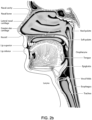
- the respiratory system of the body facilitates gas exchange.
- the nose and mouth form the entrance to the airways of a patient.
- the airways consist of a series of branching tubes, which become narrower, shorter and more numerous as they penetrate deeper into the lung.
- the prime function of the lung is gas exchange, allowing oxygen to move from the air into the venous blood and carbon dioxide to move out.
- the trachea divides into right and left main bronchi, which further divide eventually into terminal bronchioles.
- the bronchi make up the conducting airways, and do not take part in gas exchange. Further divisions of the airways lead to the respiratory bronchioles, and eventually to the alveoli.
- the alveolated region of the lung is where the gas exchange takes place, and is referred to as the respiratory zone. See " Respiratory Physiology", by John B. West, Lippincott Williams & Wilkins, 9th edition published 2011.
- WO 2011/060479 A1 shows a mask system for providing respiratory therapy to the airways of a person, the mask system constructed and arranged to be in sealing relationship with the nose and mouth of the patient in use.
- the mask system can comprise a foam cushion with a silicone membrane. The membrane curves inward into a breathing cavity and the foam cushion is positioned under the membrane to support it.
- EP2 428 241 A1 shows an interface structure located at an entrance to the airways of a patient, comprising a foam interface adapted to connect with skin surfaces, preferably under the patient's nose.
- US 2012/0080035 A1 discloses an adjustable mask system that includes a cushion with a seal having the ability to change size and/or shape.
- the cushion may be made of a foam material.
- WO 2007/009182 A1 discloses a respiratory mask comprising a first component formed from a flexible material and a second component formed from a material that is more rigid than the flexible material, wherein the first component is formed onto the second component by an overmoulding process.
- US 4 945 907 A discloses a reusable face mask that filters particulate matter and noxious and poisonous gasses from breathed air. By using two filters, selective combinations of noxious and poisonous gasses, dusts and mists may be filtered from breathed air.
- US 4 323 063 A discloses a medical face mask having the central portion of the mask made of a transparent material, providing a view of the wearer's mouth.
- US 2009/255542 A1 discloses a nose clip as a resinous strip-shaped member having aflexibility that pennits easy deformation and the shape-retaining capability that permits the shape after deformation to be retained.
- CN 101 301 505 A1 discloses a full face mask assembly including a frame, a cushion and a clip for holding the cushion on the frame.
- Obstructive Sleep Apnoea a form of Sleep Disordered Breathing (SDB), is characterized by occlusion of the upper air passage during sleep. It results from a combination of an abnormally small upper airway and the normal loss of muscle tone in the region of the tongue, soft palate and posterior oropharyngeal wall during sleep.
- the condition causes the affected patient to stop breathing for periods typically of 30 to 120 seconds duration, sometimes 200 to 300 times per night. It often causes excessive daytime somnolence, and it may cause cardiovascular disease and brain damage.
- the syndrome is a common disorder, particularly in middle aged overweight males, although a person affected may have no awareness of the problem. See U.S. Patent No. 4,944,310 (Sullivan ).
- Cheyne-Stokes Respiration is a disorder of a patient's respiratory controller in which there are rhythmic alternating periods of waxing and waning ventilation, causing repetitive de-oxygenation and reoxygenation of the arterial blood. It is possible that CSR is harmful because of the repetitive hypoxia. In some patients CSR is associated with repetitive arousal from sleep, which causes severe sleep disruption, increased sympathetic activity, and increased afterload. See U.S. Patent No. 6,532,959 (Berthon-Jones ).
- Obesity Hyperventilation Syndrome is defined as the combination of severe obesity and awake chronic hypercapnia, in the absence of other known causes for hypoventilation. Symptoms include dyspnea, morning headache and excessive daytime sleepiness.
- COPD Chronic Obstructive Pulmonary Disease
- COPD encompasses any of a group of lower airway diseases that have certain characteristics in common. These include increased resistance to air movement, extended expiratory phase of respiration, and loss of the normal elasticity of the lung. Examples of COPD are emphysema and chronic bronchitis. COPD is caused by chronic tobacco smoking (primary risk factor), occupational exposures, air pollution and genetic factors. Symptoms include: dyspnoea on exertion, chronic cough and sputum production.
- Neuromuscular Disease may encompass many diseases and ailments that impair the functioning of the muscles either directly via intrinsic muscle pathology, or indirectly via nerve pathology.
- Some NMD patients are characterised by progressive muscular impairment leading to loss of ambulation, being wheelchair-bound, swallowing difficulties, respiratory muscle weakness and, eventually, death from respiratory failure.
- Neuromuscular disorders can be divided into rapidly progressive and slowly progressive: (i) Rapidly progressive disorders: Characterised by muscle impairment that worsens over months and results in death within a few years (e.g. Amyotrophic lateral sclerosis (ALS) and Duchenne muscular dystrophy (DMD) in teenagers); (ii) Variable or slowly progressive disorders: Characterised by muscle impairment that worsens over years and only mildly reduces life expectancy (e.g.
- Symptoms of respiratory failure in NMD include: increasing generalised weakness, dysphagia, dyspnoea on exertion and at rest, fatigue, sleepiness, morning headache, and difficulties with concentration and mood changes.
- Chest wall disorders are a group of thoracic deformities that result in inefficient coupling between the respiratory muscles and the thoracic cage.
- the disorders are usually characterised by a restrictive defect and share the potential of long term hypercapnic respiratory failure.
- Scoliosis and/or kyphoscoliosis may cause severe respiratory failure.
- Symptoms of respiratory failure include: dyspnoea on exertion, peripheral oedema, orthopnoea, repeated chest infections, morning headaches, fatigue, poor sleep quality and loss of appetite.
- CPAP Nasal Continuous Positive Airway Pressure
- OSA Obstructive Sleep Apnea
- Non-invasive ventilation provides ventilator support to a patient through the upper airways to assist the patient in taking a full breath and/or maintain adequate oxygen levels in the body by doing some or all of the work of breathing.
- the ventilator support is provided via a patient interface.
- NIV has been used to treat CSR, OHS, COPD, MD and Chest Wall disorders.
- IV Invasive ventilation
- Ventilators may control the timing and pressure of breaths pumped into the patient and monitor the breaths taken by the patient.
- the methods of control and monitoring patients typically include volume-cycled and pressure-cycled methods.
- the volume-cycled methods may include among others, Pressure-Regulated Volume Control (PRVC), Volume Ventilation (VV), and Volume Controlled Continuous Mandatory Ventilation (VC-CMV) techniques.
- the pressure-cycled methods may involve, among others, Assist Control (AC), Synchronized Intermittent Mandatory Ventilation (SIMV), Controlled Mechanical Ventilation (CMV), Pressure Support Ventilation (PSV), Continuous Positive Airway Pressure (CPAP), or Positive End Expiratory Pressure (PEEP) techniques.
- Assist Control AC
- SIMV Synchronized Intermittent Mandatory Ventilation
- CMV Controlled Mechanical Ventilation
- PSV Pressure Support Ventilation
- CPAP Continuous Positive Airway Pressure
- PEEP Positive End Expiratory Pressure
- Ventilators such as the ResMed Stellar TM Series of Adult and Paediatric Ventilators may provide support for invasive and non-invasive non-dependent ventilation for a range of patients for treating a number of conditions such as but not limited to NMD, OHS and COPD.
- the ResMed Elo TM 150 ventilator and ResMed VS III TM ventilator may provide support for invasive and non-invasive dependent ventilation suitable for adult or paediatric patients for treating a number of conditions. These ventilators provide volumetric and barometric ventilation modes with a single or double limb circuit.
- a system may comprise a PAP Device/ventilator, an air circuit, a humidifier, a patient interface, and data management.
- a patient interface may be used to interface respiratory equipment to its user, for example by providing a flow of breathable gas.
- the flow of breathable gas may be provided via a mask to the nose and/or mouth, a tube to the mouth or a tracheostomy tube to the trachea of the user.
- the patient interface may form a seal, e.g. with a face region of the patient, to facilitate the delivery of gas at a pressure at sufficient variance with ambient pressure to effect therapy, e.g. a positive pressure of about 10cmH2O.
- the patient interface may not include a seal sufficient to facilitate delivery to the airways of a supply of gas at a positive pressure of about 10cm H2O.
- the design of a patient interface presents a number of challenges.
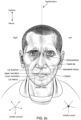
- the face has a complex three-dimensional shape.
- the size and shape of noses varies considerably between individuals. Since the head includes bone, cartilage and soft tissue, different regions of the face respond differently to mechanical forces.
- the jaw or mandible may move relative to other bones of the skull. The whole head may move during the course of a period of respiratory therapy.
- masks designed solely for aviators, mask designed as part of personal protection equipment (e.g. filter masks), SCUBA masks, or for the administration of anaesthetics may be tolerable for their original application, but nevertheless be undesirably uncomfortable to be worn for extended periods of time, e.g. several hours. This is even more so if the mask is to be worn during sleep. An uncomfortable mask may impact on patient compliance.
- Nasal CPAP therapy is highly effective to treat certain respiratory disorders, provided patients comply with therapy. If a mask is uncomfortable, or difficult to use a patient may not comply with therapy. Since it is often recommended that a patient regularly wash their mask, if a mask is not easily replaceable or difficult to clean (e.g. difficult to assemble or disassemble), patients may not replace or clean their mask and this may impact on patient compliance.
- masks for delivery of nasal CPAP during sleep form a distinct field.
- Patient interfaces may include a seal-forming portion.
- a patient interface may be partly characterised according to the design intent of where the seal-forming portion is to engage with the face in use.
- a seal-forming portion may comprise two sub-portions to engage with respective left and right nares.
- a seal-forming portion may comprise a single element that surrounds both nares in use. Such single element may be designed to for example overlay an upper lip region and a nasal bridge region of a face.
- a seal-forming portion may comprise an element that surrounds a mouth region in use, e.g. by forming a seal on a lower lip region of a face.
- a seal-forming portion may comprise a single element that surrounds both nares and a mouth region in use.
- These different types of patient interfaces may be known by a variety of names by their manufacturer including nasal masks, full-face masks, nasal pillows, nasal puffs and oro-nasal masks.
- seal-forming portion extends around the periphery of the patient interface, and is intended to seal against the user's face when force is applied to the patient interface with the seal-forming portion in confronting engagement with the user's face.
- the seal-forming portion may consist of an air or fluid filled cushion, or a moulded or formed surface of a resilient seal element made of an elastomer such as a rubber.
- seal-forming portion incorporates a flap seal of thin material so positioned about the periphery of the mask so as to provide a self-sealing action against the face of the user when positive pressure is applied within the mask.
- flap seal of thin material so positioned about the periphery of the mask so as to provide a self-sealing action against the face of the user when positive pressure is applied within the mask.
- additional force may be required to effect a seal, or the mask may leak.
- shape of the seal-forming portion does not match that of the patient, it may crease or buckle in use, giving rise to leaks.
- seal-forming portion may comprise a friction-fit element, e.g. for insertion into a naris.
- seal-forming portion may use adhesive to effect a seal. Some patients may find it inconvenient to constantly apply and remove an adhesive to their face.
- a seal-forming portion of a patient interface used for positive air pressure therapy is subject to the corresponding force of the air pressure to disrupt a seal.
- a variety of techniques have been used to position the seal-forming portion, and to maintain it in sealing relation with the appropriate portion of the face.
- Another technique is the use of one or more straps and stabilising harnesses. Many such harnesses suffer from being one or more of ill-fitting, bulky, uncomfortable and awkward to use.
- Some forms of patient interface systems may include a vent to allow the washout of exhaled carbon dioxide. Many such vents are noisy. Others may block in use and provide insufficient washout. Some vents may be disruptive of the sleep of a bed-partner 1100 of the patient 1000, e.g. through noise or focussed airflow.
- ResMed Limited has developed a number of improved mask vent technologies. See WO 1998/034,665 ; WO 2000/078,381 ; US 6,581,594 ; US Patent Application; US 2009/0050156 ; US Patent Application 2009/0044808 .
- nasal pillow is found in the Adam Circuit manufactured by Puritan Bennett.
- Another nasal pillow, or nasal puff is the subject of US Patent 4,782,832 (Trimble et al. ) , assigned to Puritan-Bennett Corporation.
- ResMed Limited has manufactured the following products that incorporate nasal pillows: SWIFT nasal pillows mask, SWIFT II nasal pillows mask, SWIFT LT nasal pillows mask, SWIFT FX nasal pillows mask and LIBERTY full-face mask.
- Patent Application 2009/0044808 (describing amongst other things aspects of ResMed SWIFT LT nasal pillows); International Patent Applications WO 2005/063,328 and WO 2006/130,903 (describing amongst other things aspects of ResMed LIBERTY full-face mask); International Patent Application WO 2009/052,560 (describing amongst other things aspects of ResMed SWIFT FX nasal pillows).
- Examples of respiratory apparatuses include ResMed's S9 AutoSet TM PAP device and ResMed's Stellar TM 150 ventilator.
- PAP devices or ventilators typically comprise a flow generator, such as a motor-driven blower or a compressed gas reservoir, and are configured to provide a controlled supply of breathable gases (e.g., air) to the airway of a patient.
- breathable gases e.g., air
- the flow of air or other breathable gases may be supplied to the airway of the patient at positive pressure may be supplied to the airway of a patient by a PAP device such as a motor-driven blower.
- the outlet of the blower PAP device or the ventilator is connected via a flexible delivery conduit an air circuit to a patient interface such as those described above.
- Ventilators or PAP devices typically include a flow generator, an inlet filter, a patient interface, an air circuit delivery conduit connecting the flow generator to the patient interface, various sensors and a microprocessor-based controller.
- the patient interface may include a mask or a tracheostomy tube as described above.
- the flow generator may include a servo-controlled motor, volute and an impeller that forms a blower.
- a brake for the motor may be implemented to more rapidly reduce the speed of the blower so as to overcome the inertia of the motor and impeller. The braking can permit the blower to more rapidly achieve a lower pressure condition in time for synchronization with expiration despite the inertia.
- the flow generator may also include a valve capable of discharging generated air to atmosphere as a means for altering the pressure delivered to the patient as an alternative to motor speed control.
- the sensors measure, amongst other things, motor speed, mass flow rate and outlet pressure, such as with a pressure transducer or the like.
- the apparatus may optionally include a humidifier and/or heater elements in the path of the air delivery circuit.
- the controller may include data storage capacity with or without integrated data retrieval and display functions.
- the present technology is directed towards providing medical devices used in the diagnosis, amelioration, treatment, or prevention of respiratory disorders having one or more of improved comfort, cost, efficacy, ease of use and manufacturability.
- An aspect of the present technology relates to apparatus used in the treatment or prevention of a respiratory disorder.
- Another aspect of the present technology may relate to methods used in the treatment or prevention of a respiratory disorder.
- One form of the present technology involves an interface that directs a treatment, such as a positive pressure breathable gas, to a patient respiratory system.
- a treatment such as a positive pressure breathable gas
- Another aspect of one form of the present technology involves such an interface that directs a treatment to the nares of the patient respiratory system.
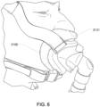
- Another aspect of one form of the present technology is such an interface that directs a treatment to the nares and mouth of the patient respiratory system but maintaining a minimal facial contact profile so as to avoid contact or coverage of a majority of a nose of patient.
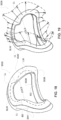
- Another aspect of one form of the present technology is a patient interface that is moulded or otherwise constructed with a clearly defined perimeter shape which is intended to match the face profile of an intended wearer.
- a patient interface that employs a foam cushion.
- the foam may optionally be part of a cushion assembly that may further implement a flexible support clip.
- the flexible support clip can be configured with dimensions and material properties so as to both support the foam cushion and complement the foam cushion's compliance.
- a relatively thin foam cushion may provide compliance to account for the fine details on the user's face, while the flexible clip can account for the more coarse aspects of the facial structure.
- Such configuration may reduce the amount of foam required for a comfortable and efficient sealing of the mask. The reduced amount of foam may minimise the overall size of the mask, make it less obtrusive and improve its aesthetic appeal.
- Another aspect of some forms of the present technology is a patient interface that is implemented as a mouth and nose mask with a substantially above the nose or under the nose seal configuration.
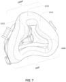
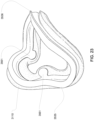
- a mask apparatus for a respiratory treatment may include a frame adapted to couple with a respiratory treatment apparatus so as to permit communication of a pressurized gas to a respiratory system of a patient from the respiratory treatment apparatus; and it may include a cushion adapted to couple with the frame, the cushion configured as a substantially under nose seal portion and a mouth seal portion, the under nose seal portion comprising a sub-nasal ridge formed as a semi-peripheral sealing boundary about both nares of the patient.
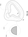
- the cushion may comprise a triangular ring having a common nasal and mouth aperture.
- the cushion may be foam.
- the cushion and the frame may form a common plenum chamber for sealing about the nares and mouth.
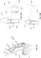
- the cushion may include a protrusion configured to ply adjacent to a nasal ala of the patient.
- the cushion may include left and right nasal ala protrusions.
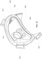
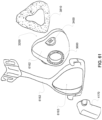
- the mask apparatus may further include a cushion support clip configured to couple with the cushion and couple with the frame.
- the cushion support clip may include first and second opposing sides, wherein the clip is configured to couple with the cushion on the first opposing side and to couple with the frame on the second opposing side.
- the cushion support clip may include a nasal plateau region and a mouth periphery region. The nasal plateau region may be approximately perpendicular to the mouth periphery region.
- the cushion support clip may include a bend region between the nasal plateau region and the mouth periphery region.
- the bend region may form an approximately nasolabial angle between the nasal plateau region and the mouth periphery region.
- the bend region may include a set of inwardly directing nasal protrusions.
- the nasal protrusions may be flexible.
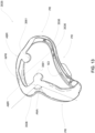
- the cushion support clip may include first and second cushion support portions, the first and second cushion support portions may be configured to provide different flexibility characteristics.
- the first cushion support portion may be a nasal support region and the second cushion support portion may be a lateral mouth support region.
- the first cushion support portion may have a higher rigidity characteristic with respect to the second cushion support portion.
- the sub-nasal ridge includes a scalloped edge.
- the cushion comprises a generally flat sealing surface.
- the cushion may include a generally curved sealing surface.
- such mask apparatus may further include a respiratory treatment apparatus configured to generate a controlled supply of breathable gas at a pressure above atmospheric pressure, the respiratory treatment apparatus including a gas delivery conduit coupled with the frame to direct the breathable gas to the frame.
- a respiratory treatment apparatus configured to generate a controlled supply of breathable gas at a pressure above atmospheric pressure
- the respiratory treatment apparatus including a gas delivery conduit coupled with the frame to direct the breathable gas to the frame.
- a cushion support clip may be flexible.
- the cushion support clip may be inwardly concave.
- the cushion support clip may be made of a material other than or different from foam.
- the cushion may be foam externally attached to a flexible clip.
- a foam surface of the cushion may be configured for direct contact with a patient's skin.
- a foam of the cushion may be a semi-open cell foam with limited permeability.
- Some versions of the present technology may include a respiratory mask for delivering a respiratory gas treatment.
- the mask may include a frame and cushion.
- the cushion may be adapted to couple with the frame.
- the cushion may be configured as a substantially under nose seal portion and a mouth seal portion.
- the cushion may further define a centrally open lip superior region.
- the cushion may include a nasal plateau region and a mouth periphery region.
- the cushion may be configured with an approximately nasolabial angle between the nasal plateau region and the mouth periphery region.
- the cushion may be a triangular ring having a common nasal and mouth aperture.
- the cushion may be foam.
- the cushion and the frame may form a common plenum chamber for sealing about nares and mouth.
- the centrally open lip superior region may be within the plenum chamber.
- the cushion may include a protrusion configured to ply adjacent to a nasal ala of a patient.
- the cushion may include left and right nasal ala protrusions.
- the respiratory mask may include a clip to removably couple the cushion to the frame.
- the clip may include flexible nasal protrusions.
- the clip may include first and second cushion support portions, the first and second cushion support portions being configured to provide different flexibility characteristics.
- a foam cushion may be implemented.
- a foam cushion assembly can be configured to seal around the mouth and over the nasal bridge, and can achieve a comfortable and effective seal.
- Such an assembly may include a foam cushion portion, a flexible clip portion and a rigid clip portion.
- the flexible clip may be arranged to complement the compliance of the cushion so as to allow a reduction in the size of the cushion.
- the rigid clip portion is generally expected to be made of generally hard material, the term "rigid" is relative with respect to the softer "flexible" clip portion (also referred to a soft clip or flexible clip).
- the rigid portion also referred to a rigid clip
- the rigid portion may have some level of flexibility. Its hardness, however, should be sufficient to facilitate attachment to the frame or to the headgear.
- the force applied to the user's face at the seal interface from headgear and treatment pressure of a respiratory treatment can be distributed over a larger surface area compared to traditional silicone based seals, resulting in better comfort as well as an improved perceived comfort. This may have a positive effect on patient therapy acceptance and, hence, compliance.
- Any mask leak can be dispersed over a wider area resulting in a more dispersed flow, which minimise “jetting” that is attributable to conventional silicone cushions. This is likely to improve patient engagement with therapy and compliance verses that associated with typical silicone sealing technology.
- Some potential benefits of such a foam cushion or assembly may include:
- a breathable foam cushion assembly can serve as a cooler skin contact region and reduce discomfort in sealing areas.
- an optional flexible clip allows a reduced overall dimension in the foam component of the cushion, compared to a foam mask without such a component. This increases stability without a compromise in comfort and sealing.
- a foam cushion assembly can be relatively small in size, unobtrusive, yet easily removable for cleaning and replacement.
- Some versions of the present technology include a foam cushion assembly for a patient interface.
- the foam cushion assembly may be adapted to couple with a patient interface frame.
- the cushion assembly may include a substantially above nose seal portion and a mouth seal portion.
- Such a cushion assembly may include a foam cushion arranged to form with the frame a common plenum chamber and for sealing about the nose and mouth of the patient, and it may include a cushion support clip arranged to couple to the foam cushion, wherein the cushion support clip may be characterised by a height to thickness ratio of at least 3, around an entire periphery of the cushion.
- the cushion support clip may be flexible.
- the flexible cushion support clip may be formed by a rigid material and the flexibility may be induced by way of introducing one or more compliance regions.
- the compliance regions may be formed by introducing a line of weakness or a region of weakness.
- the cushion support clip may have an inwardly concave shape, dimensions and material properties that, when pressure is applied to the patient interface, facilitate an air spring effect.
- the cushion support clip may be made of a material other than foam and silicone.
- the foam cushion may be externally attached to the cushion support clip.
- a foam surface of the cushion may be configured for direct contact with a patient's skin.
- the foam cushion may be a semi-open cell foam with limited permeability.
- the foam cushion may have a permeability characteristic in a range of about 0 to 20 litters per minute.
- the foam cushion may have an indentation hardness characteristic in a range of about 110.48 to 303.11 Newtons.
- the foam cushion may have a compression stress strain characteristic in a range of about 2.32 to 7.26 kilo-pascals.
- the foam cushion may have an apparent density characteristic in a range of about 24.3 to 117.85 kilograms per meter cubed.
- the foam cushion may have a compression set characteristic in a range of about 0.16 to 17.30 percent.
- the cushion support clip may be L, C and/or Z-shaped.
- the cushion support clip may include a foam cushion coupling portion, providing a contact surface to which the cushion is attached, a flexible support portion and a base portion for attaching to a second support clip or to the frame.
- the foam cushion assembly may have shape, dimensions and material characteristics of the cushion support clip selected so that at least a portion of the clip acts as a cantilever spring.
- the cushion assembly may also include a second support clip configured to couple with the cushion support clip and the frame.
- the second support clip may be more rigid than the cushion support clip and the cushion support clip may be more rigid than the foam cushion.
- the foam cushion and the cushion support clip may be integrally connected.
- the foam cushion, the cushion support clip and the second support clip may be integrally connected.
- the foam cushion assembly may be configured so that different levels of support and compliance are provided in at least some sections along a periphery of the cushion assembly.
- one or more parameters vary in at least some sections of a periphery of the clip, the parameters may include: spring constant of the clip and/or the foam cushion; cross-sectional profile of the clip and/or the foam cushion; wall thickness of the clip; angle of a contact surface of the clip to which the cushion is attached; overhang of the cushion with respect to the supporting contact surface; and foam thickness.
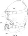
- the foam cushion assembly may further include a protrusion being configured to be, when in use, depressed by a headgear strap so as to apply pressure on a respective region of the foam cushion.
- Some versions of the present technology may include a patient interface apparatus for a respiratory treatment.
- the patient interface apparatus may include a frame adapted to couple with a respiratory treatment apparatus so as to permit communication of a pressurized gas to a respiratory system of a patient from the respiratory treatment apparatus. It may further include a cushion assembly adapted to couple with the frame of any of the versions described herein.
- Some versions of the present technology may include a mask cushion assembly for a patient interface of a respiratory treatment apparatus.
- the mask cushion assembly may include a peripheral foam cushion adapted as a seal for a mouth portion.
- the peripheral foam cushion may be further adapted as a seal for a nasal portion.
- the cushion assembly may further include a flexible support component peripherally engaged with the foam cushion and a rigid support component coupled with the flexible support component, wherein the flexible support component is formed of an air impermeable material.
- the flexible support component may be formed of a flexible material.
- the flexible support component may be formed by a rigid material, wherein the flexible support component comprises one or more compliance regions inducing flexibility.
- the compliance regions may be formed by introducing a line of weakness or a region of weakness.
- the rigid support component may include a mask frame.
- the rigid support component may include a clip for coupling with a mask frame.
- the clip may include at least one snap element.
- the flexible support component may include an internal periphery of a plenum chamber of the mask cushion assembly, the internal periphery adapted to respond to a treatment pressure provided at the mask to increase a sealing force of a seal of the foam cushion.
- the flexible support component may include an internal periphery of a plenum chamber of the mask cushion, wherein the flexible support component is configured to respond with different reaction forces in at least some regions of the periphery.
- the regions with different reaction forces may include a side of nose region and a side of mouth region.
- the flexible support component may be configured to provide different roll-in responses in different regions of the periphery of the flexible support component.
- the different regions may include an upper cheek region and a side of mouth region.
- the internal periphery may be formed with different angles in the different regions, each angle formed by a support portion and a foam cushion coupling portion.
- the flexible support component may include one or more of a 'C' cross sectional geometry and an 'L' cross sectional geometry.
- the foam cushion coupling portion may include a peripheral lip to which the foam cushion may be mounted. In some cases, the engagement of the peripheral lip and foam cushion form an overhang foam portion in at least some sections along the periphery of the lip.
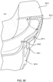
- the foam cushion may include a nasal bridge contact region.
- the nasal bridge contact region of the foam cushion may include a nasal recess.
- the foam cushion may include a substantially under nose seal portion, the under nose seal portion comprising a sub-nasal ridge formed as a semi-peripheral sealing boundary about both nares of the patient.
- the flexible support component may include a shell of a plenum chamber and a connection port for coupling to an air circuit of a respiratory treatment apparatus
- the rigid support component may include a headgear frame including a shell aperture configured for fitting about the shell
- a flexible skirt member of a mask component moves to engage and cover an inner surface of the foam cushion, the flexible skirt member may be air impermeable.
- a peripheral foam cushion may be generally planar and the flexible support component and/or the rigid support component may impart a three dimensional (3D) contour to the peripheral foam cushion, when attached to the foam cushion.
- the foam may be a polyurethane semi-open cell foam of limited permeability.
- a spring constant of a foam cushion with a nasal recess and flexible support component in a mouth region may be greater than a spring constant of the foam cushion and flexible support component in a nasal bridge region.
- a spring constant of the foam cushion and flexible support component in a cheek region may be similar to the spring constant of the nasal bridge region.
- a spring constant of a flexible clip only configuration in a mouth region may be larger than a spring constant in a cheek bone region and the spring constant in the cheek bone region may be larger than a spring constant in a nasal bridge region.
- the foam cushion may have a compression stress strain characteristic in a range of about 2.32 to 7.26 kilopascals.
- the foam cushion may have a coefficient of friction characteristic in a range of about 1.86 to 19.12 CF.
- the foam cushion may have an elongation at break characteristic in a range of about 72.3 to 369.05 percent.
- the foam cushion may have a permeability characteristic in a range of about 0 to 20 liters per minute.
- the foam cushion may have an indentation hardness characteristic in a range of about 110.48 to 303.11 Newtons.
- the foam cushion may have a compression stress strain characteristic in a range of about 2.32 to 7.26 kilo-pascals.
- the foam cushion may have an apparent density characteristic in a range of about 24.3 to 117.85 kilograms per meter cubed.
- the foam cushion may have a compression set characteristic in a range of about 0.16 to 17.30 percent.
- the foam cushion may have a tensile strength characteristic in a range of about 0.03 to 0.27 MegaPascals.
- the flexible support component may be inwardly concave.
- the flexible support component may be made of a material other than foam.
- the cushion may be made of foam and be externally attached to flexible support component.
- a foam surface of the cushion may be configured for direct contact with a patient's skin.
- One or more parameters may vary in at least some sections of the periphery of the flexible support component, the parameters may include: spring constant of the flexible support component and/or the foam cushion; cross-sectional profile of the flexible support component and/or the foam cushion; wall thickness of the flexible support component; angle of a contact surface of the flexible support component to which the cushion is attached; overhang of the cushion with respect to the supporting contact surface; and/or foam thickness.
- Some versions of the mask cushion assembly may further include a protrusion configured to be, when in use, depressed by a headgear strap so as to apply pressure on a respective region of the foam cushion.
- Some versions of the present technology may include a mask cushion for a mask frame that may include a foam cushion.
- the mask cushion may include a peripheral portion adapted as a seal for a mouth portion.
- the peripheral portion may be further adapted as a seal for a nasal portion.
- the foam cushion may further include a stretchable engagement skirt, whereby the foam cushion may be configured as a slip-over foam cover for a supporting structure.
- Some versions of the present technology may include a mask cushion assembly for a mask frame.
- the assembly may include a foam cushion, the foam cushion may include a peripheral portion adapted as a seal for a mouth portion.
- the peripheral portion may be further adapted as a seal for a nasal portion.
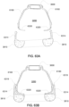
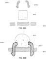
- the mask cushion assembly may further include an inner peripheral clip and outer peripheral clip.
- the clips may be configured to engage with a foam support component.
- the inner peripheral clip may engage on an inner side of the foam cushion and the outer peripheral clip may engage on an outer side of the foam cushion.
- the clips may clamp the foam cushion to secure the foam cushion to the foam support component.
- the clips may be configured to clamp the foam so as to round a patient contact surface of the foam cushion.
- the clips may further include an over-clip portion configured to depress over a top side portion of the foam cushion.
- the foam cushion may further include a slit to receive an over-clip portion.
- portions of the aspects may form sub-aspects of the present technology.
- various ones of the sub-aspects and/or aspects may be combined in various manners and also constitute additional aspects or sub-aspects of the present technology.
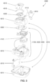
- Fig. 3 shows an example PAP device suitable for implementation with examples of the present technology
- the present technology comprises apparatus for treating a respiratory disorder.
- the apparatus may include a flow generator or blower for supplying pressurised respiratory gas, such as air, to the patient 1000 via an air delivery conduit, such as a tube, leading to a patient interface 3000.
- the present technology may involve a method for treating a respiratory disorder by applying positive pressure to the entrance of the airways of a patient 1000.
- the present technology may involve a method of treating Obstructive Sleep Apnea in a patient by applying continuous positive airway pressure to the patient with a patient interface described herein.
- Other positive pressure treatment therapies may also be provided (e.g., bi-level CPAP, etc.)
- An example PAP device 4000 in accordance with one aspect of the present technology may include mechanical and pneumatic components 4100, electrical components 4200 and is programmed to execute one or more control methodologies or algorithms, such as to control providing the continuous positive airway pressure or any one or more of the positive pressure treatment therapies.
- the PAP device may include an external housing 4010, which may be formed in two parts, an upper portion 4012 of the external housing 4010, and a lower portion 4014 of the external housing 4010. In alternative forms, the external housing 4010 may include one or more panel(s) 4015.
- the PAP device 4000 may include a chassis 4016 that supports one or more internal components of the PAP device 4000. In one form a pneumatic block 4020 is supported by, or formed as part of the chassis 4016.
- the PAP device 4000 may include a handle 4018.
- the pneumatic path of the PAP device 4000 may include an inlet air filter 4112, an inlet muffler 4122, a controllable source 4140 of air at positive pressure (preferably a blower 4142), and an outlet muffler 4124.
- One or more pressure sensors 4272 and flow sensors 4274 may be included in the pneumatic path.
- An example pneumatic block 4020 may include a portion of the pneumatic path that is located within the external housing 4010.
- the PAP device 4000 may have an electrical power supply 4210, one or more input devices 4220, a processor, a pressure device controller, one or more protection circuits, memory, transducers, data communication interface and one or more output devices. Electrical components 4200 may be mounted on a single Printed Circuit Board Assembly (PCBA) 4202. In an alternative form, the PAP device 4000 may include more than one PCBA 4202.
- PCBA Printed Circuit Board Assembly
- the processor of the PAP device 4000 may be programmed to execute a series of algorithm modules in use, preferably including pre-processing transducer signals module, a therapy engine module 4320, a pressure control module, and further preferably a fault condition module.
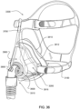
- a patient interface 3000 in any versions of the present technology may typically include optional features such as a seal forming structure 3100, a plenum chamber 3200, positioning and stabilizing structure 3300, vent 3400, decoupling structure 3510, connection port 3600, forehead support 3700, anti-asphyxia valve 3800 and/or one or more ports 3900.
- optional features such as a seal forming structure 3100, a plenum chamber 3200, positioning and stabilizing structure 3300, vent 3400, decoupling structure 3510, connection port 3600, forehead support 3700, anti-asphyxia valve 3800 and/or one or more ports 3900.
- Such features may be considered in reference at least to the examples of Figs. 4 and 36 .
- a seal-forming structure 3100 provides a sealing-forming surface, and may additionally provide a cushioning function.
- a seal-forming structure 3100 in accordance with the present technology may be constructed from a soft, flexible, resilient material such as silicone or other materials and structures described throughout this specification.
- the seal-forming structure 3100 may include a sealing flange and may further include a support flange.
- the sealing flange may be a relatively thin member with a thickness of less than about 1mm, for example about 0.25mm to about 0.45mm, that extends around the perimeter of the plenum chamber 3200.
- Support flange may be relatively thicker than the sealing flange.
- the support flange can be disposed between the sealing flange and the marginal edge of the plenum chamber 3200, and extends at least part of the way around the perimeter.
- the support flange is or includes a spring-like element and functions to support the sealing flange from buckling in use. In use the sealing flange can readily respond to system pressure in the plenum chamber 3200 acting on its underside to urge it into tight sealing engagement with the face.
- the seal-forming portion of the non-invasive patient interface 3000 comprises a pair of nasal puffs, or nasal pillows, each nasal puff or nasal pillow being constructed and arranged to form a seal with a respective naris of the nose of a patient.
- Nasal pillows in accordance with an aspect of the present technology may include: a frusto-cone, at least a portion of which forms a seal on an underside of the patient's nose; a stalk, a flexible region on the underside of the cone and connecting the cone to the stalk.
- the structure to which the nasal pillow of the present technology is connected includes a flexible region adjacent the base of the stalk.
- the flexible regions can act in concert to facilitate a universal joint structure that is accommodating of relative movement- both displacement and angular- of the frusto-cone and the structure to which the nasal pillow is connected.
- the frusto-cone may be axially displaced towards the structure to which the stalk is connected.
- a seal-forming portion forms a seal in use on an upper lip region (that is, the lip superior ) of the patient's face.
- the non-invasive patient interface 3000 comprises a seal-forming portion that forms a seal in use on a chin-region of the patient's face.
- the plenum chamber 3200 has a perimeter that is shaped to be complementary to a surface contour of the face of an average person in the region where a seal will form in use. In use, a marginal edge of the plenum chamber 3200 is positioned in close proximity to an adjacent surface of the face. Actual contact with the face is provided by the seal-forming structure 3100. Preferably the seal-forming structure 3100 extends in use about the entire perimeter of the plenum chamber 3200.
- the seal-forming structure 3100 of the patient interface 3000 of the present technology is held in sealing position in use by the positioning and stabilising structure 3300.
- the patient interface 3000 includes a vent 3400 constructed and arranged to allow for the washout of exhaled carbon dioxide.
- vent 3400 in accordance with the present technology comprises a plurality of holes, for example, about 20 to about 80 holes, or about 40 to about 60 holes, or about 45 to about 55 holes.
- the vent 3400 is located in the plenum chamber 3200.
- the vent 3400 is located in a decoupling structure 3510, e.g. a swivel.
- the patient interface 3000 includes at least one decoupling structure 3510, for example a swivel or a ball and socket.
- Connection port 3600 allows for connection to the air circuit 4170.
- the patient interface 3000 includes a forehead support 3700.
- the patient interface 3000 includes an anti-asphyxia valve 3800.
- a patient interface 3000 may optionally include one or more ports that allow access to the volume within the plenum chamber 3200. In one form this allows a clinician to supply supplemental oxygen. In one form this allows for the direct measurement of a property of gases within the plenum chamber 3200, such as the pressure.
- a non-invasive patient interface 3000 in accordance with one example of the present technology may be considered with reference to Figs. 4-7 .
- the patient interface may include any of the following features: a seal-forming structure 3100, such as a cushion 3110, a plenum chamber 3200, a positioning and stabilising structure 3300, such as one or more headgear vectors, and a connection port 3600 for connection to an air/gas circuit 4170.
- a seal-forming structure 3100 such as a cushion 3110, a plenum chamber 3200, a positioning and stabilising structure 3300, such as one or more headgear vectors, and a connection port 3600 for connection to an air/gas circuit 4170.
- one or more such features may be provided by one or more physical components.
- one physical component may provide one or more functional features.
- the seal-forming structure 3100 may be arranged to be in direct contact with the patient's skin and surround an entrance to the airways of the patient so as to facilitate the supply of air at positive pressure to the
- the patient interface may be configured as a mask to provide a sealed interface with the mouth and nares of a patient so as to direct a breathable gas under pressure to both the mouth and nares.
- a mask may be configured to be a substantially under-the-nose mask.
- the plenum chamber 3200 may be formed by a frame 3500 and cushion 3110.
- the cushion 3110 may also serve as the seal forming structure 3100.
- the frame may be adapted for coupling with a respiratory treatment apparatus so as to permit communication of a pressurized gas to a respiratory system of a patient from the respiratory treatment apparatus.
- the cushion may then be adapted to couple with the frame.
- the cushion may form a seal with a substantially under nose seal portion UNSP and a mouth seal portion MSP.
- the under nose seal portion may be formed by a sub-nasal ridge 3131 that forms a semi-peripheral sealing boundary about both nares of the patient.
- a seal may be achieved with both nares and the mouth while in some cases avoiding a seal portion or other mask contact structure at a central region of the lip superior LS.
- Such a mask may provide a more open and comfortable feel for users such as when compared to mouth masks that may be combined with nasal prongs, while still providing an effective seal.
- foam such as a semi-open (or semi closed) cell foam.
- the cushion may be a foamed silicone material or a polyurethane foam, etc.
- a very low durometer thermoplastic elastomers (TPE), thermoplastic polyurethane (TPU), thermoplastic polyurethane (TPV), silicone or rubber material might be implemented.
- TPE thermoplastic elastomers
- TPU thermoplastic polyurethane
- TPV thermoplastic polyurethane
- silicone or rubber material might be implemented.
- TPE thermoplastic elastomers
- TPU thermoplastic polyurethane
- TPV thermoplastic polyurethane
- silicone or rubber material might be implemented.
- the compliant nature of foam allows it to, under relatively small tension force, compress into intricate facial features and affect a good seal. This, combined with the easy adaptability and softness experienced by the patient, provides for a relative fast and easy mask set-up.
- the porosity of the foam also exhibits better breathability than silicone and may permit wicking away
- the cushion and/or frame may define a single chamber, such as the plenum chamber 3200 that is illustrated in FIG. 7 , which covers the patient's mouth and the nares of the nose from underneath.
- the cushion may have a substantially oval and/or triangular shape.
- the sealing surface may continuously extend substantially in two plains - one plane that allows it to seal with the mouth and a second plane that facilitates the seal under the patient's nostrils.
- the second plane may form an angle with respect to the first plane.
- the angle may be approximately close to ninety degrees or approximately perpendicular, but may be slightly larger or slightly smaller. Such an angle may approximate the nasolabial angle.
- Such a single chamber foam cushion may be designed to attach to a frame directly or by way of a clip as discussed in more detail herein.
- the seal around the mouth and the nares of such a mask can be produced through the interaction between the patient's face and the combined reaction of the assembly (e.g., frame, flexible clip, and/or cushion) and subject to tension from headgear.
- the structures of the components when assembled can work together to provide variable amounts of compression around the nose and mouth so that an effective seal is produced in these areas.
- Figs. 8 and 9 show a cross sectional view of a sub-nasal region of a portion of the seal including an example sub-nasal ridge 3131.
- the figures illustrate a mechanism for achieving the seal in the sub-nasal region.
- the headgear When the nose is applied onto the cushion (e.g., foam) in the region of the sub-nasal ridge, the headgear may be tightened.
- the headgear vectors help to enforce a seal at the periphery of both of the nares through the combination of the cushion (e.g., foam) and/or the cushion support structure 8800 (e.g., clip 3535) rolling inwards (illustrated by arrows RR in Fig. 9 ) and closing around the periphery of the nares.
- the flexibility of the combination of cushion and/or cushion support structure can enable the cushion to align to the alar angle and to the Nasolabial angle of the nose.
- a greater sealing force can be applied to the periphery of the nares.
- the reaction force in the cushion and the cushion support e.g., clip and/or frame
- the generated gas pressure e.g., from a flow generator coupled to the mask assembly
- the cushion e.g., foam
- occlusion of the nares may be a potential for occlusion of the nares by some cushions during set-up or use.
- the seal around the nares is associated with the compression of some foams, it can lead to nasal occlusion occurring at mask set-up before pressure is applied to the mask.
- a balance can be attained between the foam thickness, the foam profile around the periphery of the nares and cantilever spring characteristics of the support structure (e.g., clip if used).
- a thin foam section such as in the nasal region may be suitable.
- a foam thickness of about 8 to 20 mm e.g., 13mm
- the foam internal profile may be aligned and/or shaped to match the nares opening such as at their periphery.
- a soft elastic material such as silicone, TPE, TPU etc.
- Such a material can be configured to pass on a light cantilever spring affect onto the nose.
- a pressure treatment such as a CPAP treatment
- occlusion may be avoided at the nares.
- the internal profile (as illustrated in Fig. 9 ) of the foam cushion can provide relief around the nares.
- the foam may be compressed around the periphery of the nares by the internal CPAP pressure inflating the nostrils.
- the foam rigidity should be no greater than the reaction force generated by the internal CPAP pressure inflating the nostrils. This situation can hold the nares open during CPAP and no occlusion will result.
- the cantilever spring force of the cushion support (e.g., clip and/or frame) can be soft enough to allow the nose to press into the foam cushion at set-up without occluding the nares. Conversely, the spring force of the cushion support can provide enough reaction force to press the foam cushion into all the sealing zones of the mask. This may be significant for areas such as at the corners of the nose.
- the frame 3500 may be a separable component from the clip 3535 and the cushion.
- the frame may include a set of fasteners 3537. The fasteners may be employed for connection of head gear (not shown) to position and support the mask assembly for use.
- the frame may also optionally, include a vent 3400.
- the vent 3400 may be constructed and arranged to allow for the washout of exhaled carbon dioxide.
- the vent 3400 may be formed by a plurality of holes, for example, about 20 to about 80 holes, or about 40 to about 60 holes, or about 45 to about 55 holes.
- the vent 3400 may be located in the plenum chamber 3200. Alternatively, the vent 3400 may be located in a decoupling structure, e.g. a swivel or other coupler.
- the frame may typically include a connection port 3600.
- the connection port 3600 allows for connection to an air circuit 4170, such as for a connection with a respiratory treatment apparatus or flow generator. Such a connection to an air circuit may be by way of a decoupling structure as previously mentioned.
- the patient interface 3000 may include an anti-asphyxia valve (not shown).
- the frame may include one or more additional ports. Such additional ports may permit access to the volume within the plenum chamber 3200. For example, such a port may permit introduction of a supply of supplemental oxygen.
- Such a port may also serve as a coupler or housing for a sensor for direct measurement of a property of the gases within the plenum chamber 3200, such as pressure.
- the frame may contain a flange 3515 around its rear (patient proximate side) periphery such as the one illustrated in FIG. 12 .
- This flange may vary in angle and width around the periphery of the plenum chamber in order to follow the curvature of the sections of the face where a seal is to take place.
- the flange may extend generally parallel to those areas near where the seal is to exist on the patient's face.
- a varying angled flange can work together with the headgear vectors to impart a desired amount of cushion compression to the varying parts around the mouth and the nares to achieve a comfortable and effective seal.
- the mask assembly may employ a clip 3535 as illustrated in Fig. 13 or Fig. 14 .
- the clip may be releasably attachable with the frame so as to permit a convenient replacement of the cushion that may be applied to the clip.
- Figs. 20 and 21 illustrate the clip (without a cushion) coupled to the frame.
- any one or more of the features of the clip described herein may optionally be integrated with the structure of the frame itself and the cushion applied thereto.
- the clip's profile can assist in imparting form to the cushion so as to configure the cushion into its multi-dimensional shape (e.g., multi-plane) suitable for conforming to the person's face so as to form a good seal in an under-the-nose configuration.
- the clip may be formed with a bend or angled region ABR.
- the angled region ABR permits an angle between a nasal plateau region NPR and a mouth periphery region PR.
- An approximately nasolabial angle ANA may be formed by a plane of the mouth periphery region and a plane of the nasal plateau region.
- a 2D flat clip may be used.
- the 3D shape is imparted to the flexible clip / cushion combination by attachment onto a 3-D shaped frame.
- the clip may be permanently coupled to the frame or include connectors 3536, such as those illustrated in FIGs. 13 , 22 and 23 to facilitate its removable coupling with the frame.
- These elements may be formed around one side (e.g., the lower periphery or distal side) of the clip where it interfaces with the frame. Additional examples of such connection elements are explained in more detail herein with reference to Figs. 32-35 .
- the clip's opposing side e.g., upper peripheral surface or patient proximate side
- provides a connection or landing surface for attachment of the cushion e.g., the foam ring.
- the features of the clip may serve as a suspension for the cushion.
- the clip's body may generally be approximated with a curved surface.
- the cross-sectional profile of the clip around the clip's periphery may differ in different sections of the clip so as to provide different regions of flexibility/rigidness to the cushion. Examples may be considered with reference to the cross sectional views of Figs. 15, 16 and 17 .
- the clip may be formed so as to have an open or concave wall 3535W with a cross-section along the clip's periphery that may vary in geometric shape.
- These cross-sectional shapes may be, for example, formed as a U-shape such as that shown in Fig.
- each shape shown in Figs. 13 , 15, 16 and 17 with reference character SO
- the opening of each shape can be directed inwardly towards the center or plenum chamber of the mask.
- These different wall structures may have different flexibility characteristics.
- Such cross-sectional shape(s) can enable the clip to act as a spring or cantilever-type spring.
- Such a spring configuration can permit the foam cushion to further conform to the face and compress towards it once alignment has been achieved, improving cushion compliance to the face.
- the clip (or frame) may be formed with a flexible peripheral lip that variably supports the foam cushion.
- Pressure within the plenum chamber formed between the mask frame, clip, cushion and the face of the patient acts on the inside of the clip section (e.g., the shape opening SO of the wall) and cushion and pushes the peripheral lip and the cushion towards the patient's face, thereby reinforcing the seal created by the cushion.
- the wall of the clip may also be chosen to have thickness and flexibility to allow the air pressure to create an air spring effect, further contributing to the compliance of the seal.
- the wall geometry around the periphery of the clip may vary in order to alter the stiffness or flexibility around the nose and mouth sealing regions. Different stiffness/rigidity may be achieved in these different sections of the face to achieve a balance between good seal, comfort and stability. For example, around the nose, a softer seal can be achieved as the nose is sensitive to pressure, whereas the sides of the mouth can withstand larger sealing pressures without discomfort. Thus, the flexibility of the clip (or frame) may impart these different flexibility characteristics.
- support for the cushion in the nasal sealing area may be formed as the flexible cross-section "U" geometry illustrated in Fig. 15 .
- the clip wall (concave wall 3535W) may then have a cushion support surface 3538 and a frame coupling surface 3539 for a connector as discussed herein.
- support for the cushion in the sealing area at the sides of the mouth may be formed by a flexible wall having a cross sectional shape resembling an "L" geometry as illustrated in Fig. 16 .
- support for the cushion in the sealing areal at the lower part of the mouth may be formed by a flexible wall having a cross sectional shape resembling the "C" geometry as shown below in Fig. 17 .
- two active portions of the clip's structure are the peripheral lip 3540 that form an effective cantilever over-hang portion and a middle transverse portion 3541 of the clip's periphery between the frame coupling surface 3539 and the cushion support surface 3538.
- Both of these components can act as springs and provide a sealing reaction force through their deformation. Distribution of the clip-contributed sealing force around the mouth may be governed by the clip's material and geometry. Moreover, the force may be controlled by the user depending on the amount of tightening of the headgear of the mask.
- the flexible clip may be provided with an oversized peripheral lip that increases the support of a foam cushion width that may be larger than the support surface of the peripheral lip.
- Such variations in the width of the peripheral lip can produce different reaction forces around the periphery of the mouth cushion. Beam and bending principles may show that, in isolation, a shorter peripheral lip will produce a stiffer mechanical system as there will be less clip deflection for a certain unit force than there will be for a longer peripheral lip.
- Such a clip may be considered with reference to the cushion support structures of Figs. 14 , 18 and 19 .
- Sizing of the width (shown in Fig. 18 as arrow LW) of the peripheral lip also allows for introducing variations in the seal geometry. For example, different (e.g., narrower) widths in the peripheral lip area proximate to the nose and mouth may help to achieve different reaction sealing forces in these areas.
- the profile for the clip's peripheral lip may be changed to that shown by the dashed line.
- the resulting clip is illustrated in Fig. 19 .
- a shorter lip width (shown at arrow SLW) may be provided at the peak of the nasal plateau region for less flexibility.
- a relatively longer lip width may be provided proximate the centrally open lip superior region COLS for more flexibility.
- the reaction force of such a clip can vary around the periphery as a result of such changing widths of the peripheral lip or cantilever arm.
- the width of the cushion may be similarly varied.
- the width of the cushion may be relatively constant despite the change in support structure width around its periphery such as shown in Fig. 23 .
- the foam's geometry profile may not follow the clip's geometry exactly.
- the final force profile of the mask can be affected by the combination of the clip and the compressing foam.
- Adjustments to flexibility around the sealing periphery may also be achieved by varying the thickness of the lip.
- a lip thickness value along the sides of the mouth toward the nasal peak portion may be approximately double that of the thickness along the bottom of the mouth.
- Such a ratio can provide less flexibility in the nasal region and relatively more flexibility in the lip inferior region.
- peripheral lip thickness may be in a range of about 1.5mm to 2.5 mm, such as about a 2.2mm (+/-0.1mm) relatively constant thickness from the region proximate to the sides of the mouth to the nasal peak region.
- the region of the peripheral lip proximate to the lip inferior (around the bottom of the mouth) may be in the range of about 0.75mm to 1.25mm, such as about a relatively constant 1.0mm (+/-0.1mm) thickness.
- the body depth (illustrated in Fig. 14 as arrow BD) may be relatively constant about the periphery of the clip.
- the body depth of the clip (that portion that does not connect to the cushion or the frame) may be in a range, for example, from about 8mm to 15mm or for example a depth in a range of about 11mm to 13mm.
- additional features may be formed with or applied to the cushion support structure to further affect the performance of the seal, such as flexible nasal protrusions.
- flexible nasal protrusions Such an example is illustrated with respect to the clip of Fig. 13 , which is also shown applied to a frame in Figs. 20 and 21 .
- the clip also contains extra cantilever protrusions 3561 that may further serve as cantilever springs. With these elements, the clip can press the foam into hard-to-seal areas such as the corners of the nose, effectively providing a variable level of cushion compliance.
- the cushion support (clip or frame), or portions thereof, may be molded from different grades of thermoplastic elastomers TPE. Grades of different hardness may be used. Generally, a TPE material may be more beneficial to silicone as it may be more easily molded onto some cushions (e.g., foam) and its processing time may be faster than silicone. However, other elastic or flexible materials may be used such as thermoplastic polyurethane (TPU), thermoplastic polyurethane TPV or rubber, etc. By way of further example, in some cases, the flexible support structure (e.g., clip) may be formed with silicone, such as a room temperature vulcanizing RTV silicone.
- the cushion and cushion support structure e.g., clip
- the cushion may play a greater part in conforming to the face of the user purely because it is the softer component and therefore may compress more.
- the foam and flexible support structure will reach an equilibrium shape, in which a seal is created.
- Example cushions for the mask assemblies of the present technology are illustrated in Figs. 24 and 25 .
- the cushions may be foam and form a triangular or oval shaped ring and may have a common nasal and mouth aperture.
- the corners may be rounded.
- the cushion has a generally flat patient contact surface PCS.
- the edges may be rounded.
- the cushion profile along is periphery may have a generally curved patient contact surface PCS.
- Other cushion profiles may also be implemented.
- the frame or clip contact side of the cushion may be generally flat or otherwise conform to the contact surface of the cushion support structure.
- the cushion when connected to the clip or frame as illustrated in Figs. 26 and 27 , the cushion may deform to a multi-planar shape as previously discussed that is better for sealing.
- the triangular shape when so deformed, enables the cushion to produce its seal around the outer periphery of a portion of the nares, into the corners of the nose and around the side and the bottom of the mouth while maintaining a substantially under-the-nose configuration and providing for a centrally open lip superior region.
- the mask may have a substantially non-contact area in the central lip superior region between the upper vermillion and the columella in the sub-nasal region. Moreover, this non-contact region may be within the plenum chamber during use.
- the cushions of Figs. 26 and 27 are generally uni-planar and are deformed by the frame or clip to have their multi-planar use configuration (e.g., with an nasolabial angle between the nasal plateau region and the mouth periphery region), in some cases the cushion or foam may be pre-formed or pre-cut in the multi-planar shape consistent with the shape of the clip or frame.
- the cushion may be adhered to the support structure such as with glue, spray adhesives or hotmelts, etc. In some cases, it may be adhered by ultrasonic welding. In some cases, the cushion may be sewn and adhered.
- the join may also be implemented with an intermediary material such as a tape (e.g., a double sided adhesive tape).
- the support structure e.g., clip
- the cushion may be over molded to the cushion.
- the frame may provide the shape forming structure and surface to hold the cushion (e.g., foam) in the desired profile for patient sealing.
- the cushion foam may provide some or all of the necessary spring and softness to effect the seal and provide comfort to the patient.
- some of the previously described flexible features e.g., cantilever components of the clip
- some of the flexible properties of the clip may be imparted to the foam by using a secondary layer of cushion rather than the clip.
- a secondary cushion layer may be applied to the patient contact foam layer and may have different flexibility/rigidity properties when compared to the first foam layer.
- the second layer of the dual cushion may be applied directly to the frame without the clip.
- the foam cushion may be a replaceable item (in some embodiments the replaceable item may include the cushion/clip combination).
- the cushion may be directly attached to the frame through an adhesive membrane located on the foam (or on a surface of the respective clip (either flexible or rigid). In such a case, the cushion may be simply removed, and a different cushion, with a new adhesive strip, may then be attached to the reusable frame (or reusable clip).
- the foam cushion and frame may be co-molded. In some such cases, the cushion and frame unit may then be discarded together.
- the cushion 3110 may include additional features.
- the cushion may include an indent, such as a scalloped notch 3763, such as in the nasal plateau region of the cushion as an alternative to being a generally flat sealing surface.
- the indent may be formed by a semi-peripheral cut of an edge of the cushion in the nasal portion of the seal.
- the cut may form a rising edge from a centrally lower position to a radially higher position.
- Such a semi-peripheral area may provide a cupping support around the nose.
- the cupping geometry may provide a greater surface area (bearing surface) .
- the scalloped edge shape feature may replicate the topography under the user's nose.
- the scalloped notch may also improve sealing in the sub-nasal ridge area and may provide improved nasal comfort. It may also serve to minimize nose inflation.
- the feature may also provide a perceptively distinct landing area for patients to place their nose, resulting in a more intuitive set-up.
- the notched area or the nasal plateau region may be marked to provide an indication of nasal location for user installation. For example, the area may have a distinct color with respect to the remaining areas of the cushion.
- the shape of such a notch may be defined from any of the following anthropometric features: width between the labial insertions of the alar base; length of the ala; nasal ala-slope angle; inclination of the columella; nasal tip protrusion; width of nose.
- the depth of the indent detail may be based on any of: the inclination of the columella; patient perception with respect to providing sufficient indication as to where the under nose section of the mask should be worn; sufficient surface to seal around the edge curvature of the nose; sufficient support around the periphery of the nose to prevent the nose from blowing out such as due to pressure from a pressure treatment.
- the indent such as the scalloped nasal detail
- the indent can effectively cup the lower periphery of the nose and may provide additional surface area for sealing and comfort.
- it may work in conjunction with other components of the mask assembly (clip and frame) during use to effectively serve as a seal.
- the sealing interface may shift or extend or both, from under the nose to under and/or partially up the sides of the nose.
- the force applied to the nose from the headgear and the treatment pressure from the seal interface may thereby be distributed over a larger surface area, resulting in better comfort.
- the geometry of the indent in the foam cushion can change to accommodate a range of nasal sizes.
- a nose that is pressed into the scalloped detail, for example, during set-up of the mask will displace foam until the foam conforms to the nose.
- the flexible spring nature of the cushion support structure e.g., clip and/or frame
- the cushion support structure can provide a resistive force at this stage to prevent the nose from fully pushing through the foam. Under treatment pressure, the foam can be pressed back against the nose which helps to provide an effective seal.
- the indent may be manufactured as part of a complete compression cutting process for the cushion.
- the feature may be manufactured by a secondary process such as thermoforming, ultrasonic welding or cutting.
- the whole cushion including the scalloped nasal detail may be manufactured from a single compression cutting or thermoforming process.
- the cushion may also include one or more protrusions.
- Such protrusion(s) may be included on the surface of the cushion.
- one or more protrusions can be so disposed so that, when the mask is fit on the patient's face, the protrusions extend further out of the cushion into a portion of the patient's face.
- the protrusions may provide additional structural support and a better seal.
- a set (e.g., pair) of protrusions 3764 such as one or more approximately oval projections or of another shape, are illustrated in the cushion and mask of Figs. 29, 30 and 31 .
- each protrusion is disposed so as to extend on the left and right sides of the nose (e.g., left and right nasal ala protrusions).
- each protrusion may be configured to ply adjacent to a nasal ala of the patient. As such, they may assist with buttressing the cushion's seal at the difficult sealing areas on both sides of the nose.
- the nasal protrusions while useful, are optional. An effective seal in these difficult regions may also be achieved by other means, including increasing the thickness and varying the shape of the foam cushion in these areas. For example, a narrowing may be introduced at the sides of the nasal area of the cushion to facilitate a better seal.
- connection between the clip and frame may be implemented with various structures. Some examples are illustrated in Figs. 32 through 35 .
- the cushion/clip assembly can be detachable from the frame so as to permit regular replacement of the cushion in the case that the cushion may have a shorter useful life when compared to the frame.
- connection structures for anchoring the clip to the frame may include: tongue and groove geometry; a stretchable periphery skirt to extend around an edge of the frame; a peripheral edge that connects by interference fit, such as one similar to air-tight food containers; a tongue and slot interface with secondary lip seal or gasket present.
- the connection structures of the clip may correspond to existing mask frames to permit retrofitting of the cushion designs described herein with existing mask frames.
- the clip and frame may be coupled together by a bulbous ridge 3572 and channel 3574.
- the frame may be formed with the channel and the clip may include the ridge.
- a cross sectional view of the ridge and channel may appear as a ball and socket.
- the soft flexible (e.g., TPE, silicone or other flexible material) bulbous ridge may be pressed into the rigid channel frame (e.g., plastic) to provide a seal and mechanical retention.
- snap fingers 3576 may also aid assembly and component de-molding.
- the clip and frame may be coupled together by a skirt 3578 and flange 3515 such as the flange extending continuously around the plenum chamber of the frame 3500.
- the skirt 3578 of the clip may be a semi-rigid element (e.g., TPE, polypropylene or other similar semi-rigid material) continuously extending around the ring of the clip. Plying the skirt so as to cup it over the flange may then serve as a seal and provide mechanical retention.
- the clip and frame may be coupled together by a snap shoulder 3580 and engagement cavity 3582 continuously or semi-continuously extending around the periphery of the clip and frame.
- a snap may be formed on a rim of the clip 3535.
- the rim and snap may be displaced by a more rigid frame upon engagement, such as when the snap shoulder, which may be a semi-rigid material (e.g., plypropylene) is plied into the engagement cavity 3582.
- the surface engagement of the rim and frame may provide a seal and the snap shoulder and engagement cavity coupling can provide a mechanical retention.
- the clip and frame may be coupled together by a taper lock (shown in exploded view 3583).
- a peripheral rim 3702 of the frame which may be rigid, may be retained in a peripheral channel 3585 of the clip.
- a taper element 3586 of the frame may couple with a taper receiving channel 3587 of the clip, which may be flexible (e.g., silicone, TPE, etc).
- the taper element and the taper receiving channel may be formed so as to continuously or semi-continuously extend around the periphery of the clip and frame. The taper element and taper receiving channel may then aid mechanical retention of the frame and clip components.
- the foam cushion can be in direct contact with the patient's skin.
- the compliant nature of foam allows it to, under relatively small tension force, compress into intricate facial features and affect a good seal. This, combined with the easy adaptability and softness experienced by the patient, provides for a relative fast and easy mask set-up.
- the foam also exhibits better breathability than silicone.
- the use of foam is associated with better permeability (associated by many users with a "different feeling on the face verses silicone") and reduced discomfort in the areas of contact in the sealing areas.
- the foam cushion may generally be formed by open cell foam, in which the majority of cells are open; by closed cell foam, in which the majority of cells are open or by semi-open (or semi-closed) cell foam, which is formed by a mixture of open and closed cells.
- the discussed technology may use a semi-open cell foam in which the number of open cells is significantly higher than that of the closed cells. This ensures limited permeability and a smaller leak through the cushion.
- the specific range of permeability values having such limited permeability and found suitable for the disclosed technology is discussed later in the text. Other ratios between the number of open and closed cells can also be used.
- various actions may have to be taken to mitigate the increased permeability.
- one such action is extending the flexible clip or other non-permeable membrane to cover the inner surfaces of the foam cushion and reduce the overall permeability.
- open cell foams or closed cell foams may also be used according to the discussed technology.
- foam cushions previously used are either not permeable or may include a secondary layer over the foam to stop air from passing through the foam. Both options remove the breathability benefit of a foam seal. Only traditional foam full face masks having sealed or non-permeable foam cushions were compatible with current respiratory therapy for obstructive sleep apnea (OSA).
- OSA obstructive sleep apnea
- a foam layer may be attached to a silicon cushion to improve the sealing quality and the comfort associated with the mask. In some circumstances, such arrangements, may be large in size and less comfortable, and may make it more difficult for the user to disassemble, assemble and clean the mask.
- a foam cushion may be implemented.
- a foam cushion assembly can be configured to seal around the mouth and over the nasal bridge, and can achieve a comfortable and effective seal.
- Such an assembly may include a foam cushion portion and a cushion support structure (e.g., a support clip portion).
- a cushion support structure e.g., a support clip portion
- the support clip portion may be a flexible (or soft) clip portion configured to complement the compliance of the cushion so as to allow a reduction in the size of the cushion.
- the foam cushion can be externally attached to the cushion support clip. Such an external attachment can permit the foam surface of the cushion to be configured for direct contact with a patient's skin.
- the cushion 3810 which may be made with foam, defines a single area that peripherally covers the patient's mouth and nose (approximately midway up the nasal bridge, but this can vary depending on the face anatomy of the specific patient).
- the foam cushion may, for example, be made from any suitable material such as one or more of the following example materials: Polyethylene, Polyurethane, Ethylene vinyl acetate (EVA).
- EVA Ethylene vinyl acetate
- the foam cushion may be a semi-open closed cell foam, such as one made of polyurethane.
- the cushion of semi-open cell foam may have a limited permeability such as in the ranges described in more detail in this specification.
- the cushion 3810 may have a substantially triangular or pear-like shape with a sealing face that follows the contours of a user's face.
- the single chamber foam cushion is designed to be attached to a first support (e.g., flexible) clip 3812 that is itself attached to a second, more rigid, clip 3814 (as shown in Fig. 38 ) or directly to the mask frame 3816.
- the first support clip 3812 can be a flexible clip that is more rigid than the foam cushion, but softer or more flexible than the second clip 3814. It is the combination of the foam and a flexible clip that defines the physical properties of the overall sealing interface.
- the flexible clip allows the interface to accommodate major variations, and to successfully conform to the contours of the patient's face.
- the compliant nature of the foam cushion provides micro-adjustment and forms a comfort interface layer that interacts with the patient's skin.
- the cushion assembly or cushion mask may include a protrusion, or an alignment protrusion, that may be configured, when in use, to be depressed by a headgear strap so as to apply pressure on a respective region of the foam cushion.
- a protrusion 3813 may optionally be included on the outer surface of the first support clip 3812 (e.g., flexible support clip) on both sides of the mouth (e.g., both symmetrically located about the mouth), in such a manner that a respective headgear strap may pass over each protrusion, as shown in Fig. 37 .
- Such an arrangement may allow for better sealing at the sides of the mouth when dealing with facial width variations. When tightened, the headgear may depress the protrusion toward the patient's face.
- the protrusion may be located on the outer surface of the foam cushion or the rigid clip. Protrusions of different height/thickness and located on different components (i.e. one located on the rigid clip and the other on the flexible clip) can also be used, e.g. to create a gradient of inwardly directed pressure along the side of the mask.
- the projection may extend across both the foam cushion and the flexible clip.
- a flange may be formed to extend from the frame to apply inwardly directed force and enhance the seal in a similar manner.
- the flexible clip or even both the flexible and the rigid clips may be omitted by directly applying a foam-only cushion assembly to the frame. Such a design, however, may require the cushion to be of a substantial thickness and height.
- the implementation of a clip, even of a rigid one, and especially of a flexible clip or a combination of soft and rigid clips as described here, allows reduction in the dimensions of the foam cushion, without compromising on compliance, sealing and comfort.
- One role of the rigid clip is to facilitate removable attachment of the foam/clip assembly to/from the frame for cleaning or replacement.
- Components of a foam cushion assembly 3901 are shown in Fig. 39 .
- An assembled view of the foam cushion assembly 3901 is shown in Fig. 40 .
- a frame coupling side FCS of a rigid second clip 3814 may include structures for removeably coupling the second clip to a mask frame 3816.
- a coupling ridge 4022 may be provided to engage with a corresponding structure of the mask frame.
- the coupling ridge 4022 may help to form a seal, such as with an interference fit, to prevent escape of treatment pressure at contact surface of the mask frame and the second clip at the frame coupling side FCS.
- One or more optional engageable snap elements 4024 may permit a snap-fit or snap-lock of the second clip to the mask frame.
- Such a snap element may be flexibly resilient so as to bend against a corresponding receptacle of the mask frame until a ridge stop 4025 may engage with an edge of the receptacle or aperture of the mask frame.
- a taper 4027 at the top edge of the snap element may induce the bending of the snap element during coupling of the second clip to the mask frame until the ridge stop 4025 passes into the receptacle or aperture of the mask frame and thereby locks within the receptacle or aperture of the mask frame.
- the snap element may be formed on the mask frame and a corresponding receptacle may be formed on the second clip. A manual bending of the snap element (s) may then permit the removal of the second clip from the mask frame.
- the foam, flexible clip and rigid clip are formed together or permanently attached to each other, as shown in Fig. 40 , forming an integral cushion assembly.
- the foam and flexible clip form the compliant portion of the assembly, while the rigid clip provides the mechanism to attach the cushion assembly to the mask frame. This allows the cushion assembly to be removed for cleaning and/or replacement.
- a rigid clip can enable a rigid connection between the cushion assembly and the mask frame which makes the mask more convenient for handling and more durable.
- the components of the cushion assembly e.g., the foam cushion, the flexible clip and the more rigid clip
- they may be separable elements, as shown in Fig. 39 .
- foam cushion and the flexible clip can be permanently attached to each other, but detachably connected to the rigid clip.
- the flexible clip and the more rigid clip can be permanently attached to each other but detachably connected to the foam cushion.
- the mechanisms of such removable attachment may be those known in the art and may include adhesive layers (for attaching the foam to the flexible clip), interference fits and snap-locking engagements.
- the periphery of the more flexible components, such as the flexible clip can also be stretched over the periphery of the more rigid component, such as the frame or the rigid clip.
- any combination of the three components is possible and alternative design variants could include a cushion assembly comprising only a foam cushion; a foam cushion and a flexible clip or a foam cushion and a hard clip.
- a foam cushion may itself be formed as a slip-over foam cover component for other mask components, assemblies or mask cushions.
- a foam cushion overlay may be formed as or with a stretchable engagement skirt. The skirt or foam skirt may then be stretched over an underlying structure defined by any mask component, such as a frame, a clip or even a silicon cushion.
- any mask component such as a frame, a clip or even a silicon cushion.
- the foam cushion is arranged to be in direct contact with the patient's skin.
- the seal around the mouth, the sides of the nose and the nasal bridge is produced through the interaction between the patient's face and the combined reaction force of the frame (which may be applied to the cushion assembly by way of the hard clip); the flexible clip and the foam cushion, to the headgear tension.
- the frame which may be applied to the cushion assembly by way of the hard clip
- the flexible clip and the foam cushion to the headgear tension.
- a seal is generated along the foam's contact surface with the patient's face, such as over the nasal bridge and around the sides of the nose and mouth.
- the seal is caused by a combination of foam compression and/or deflection and compression of the flexible clip.
- the flexibility in the combination of foam and flexible clip can enable the foam mask to conform well to the patient's facial profile.
- reaction forces in the cushion and the flexible clip caused by the deflection and compression of the cushion and clip by the headgear, result in a reaction vector that is directed from the frame support and towards the patient.
- the structure of the foam cushion and the flexible clip is such that the treatment pressure (e.g., CPAP) accumulated inside the mask plenum chamber also acts upon the inner surface of the flexible clip and the foam, pushing them outwardly and compressing the foam against the user's face.
- the arrangement utilizes further the pressure in the plenum chamber and helps maintaining sealing pressure.
- the foam and clip work in unison to respond to the compression force imparted to the frame by the headgear vectors.
- the foam and clip will reach an equilibrium shape, in which a seal is created and retained.
- the clip may provide a reaction force that is substantially larger than that provided by the foam cushion.
- the reactions forces of both the clip and the foam cushion may vary along their periphery.
- the compressed foam may provide relatively small elastic reaction force in some sections of the cushion periphery, and a larger force in other sections.
- the flexible clip may be peripherally and inwardly concave so as to have a concave profile or inwardly concave shape. This can allow for the pressure to act upon the inner surface of the clip so as to enhance the sealing of the mask.
- the spring constant provided from the mid area of the shape may act as a support beam that creates the main reaction force in response to the tension force applied by the headgear.
- a peripheral lip for supporting the foam can serve as a cantilever that presses the foam towards the patient's face to strengthen the sealing engagement.
- the overall open (concave, C-shaped or L-shaped) structure of the clip allows the air pressure in the mask to be applied to the inside surface of the peripheral lip. This surface is located opposite to the foam supporting (also sealing) surface.
- the mask pressure pushes the peripheral lip, and therefore compresses the foam cushion towards the patient's face, thus further strengthening the sealing engagement and potentially assisting with reducing any air permeability of the foam.
- the pressure will still be applied to the foam cushion.
- the concave shape of the clip means that at least a portion of the lower surface of the foam cushion 3810 is covered by a non-permeable material of the flexible clip, as best seen in Fig. 41 . This can be used to control the leak through the cushion and increase the pressure within the mask plenum chamber.
- the clip can be extended to cover at least a portion of the outer side wall of the cushion 3810, as long as it does not get in contact with the patient's skin.
- the clip can be extended to cover at least a portion of the outer side wall of the cushion 3810, as long as it does not get in contact with the patient's skin.
- one positive outcome of such a design may be the fact that a portion of the foam is unsupported by the flexible clip and, as a result, the foam may tend to "roll-in" when the headgear is tightened. Such a roll-in effect may be beneficial for the sealing in some areas of the nose, for example.
- the foam has a varying cross section from the bridge of the nose to the bottom of the mouth, and is symmetric through the center plane.
- the geometry of the foam is affected by the anthropometric data used in the overall design of the flexible clip as well as the specification of the foam material (e.g., hardness, compression set, permeability, compression stress strain, density etc.).
- the cushion may be configured with a varying cross section that can be divided into three regions, nasal bridge MNBR, sides of nose region MSNR and sides of mouth region MMR, with a smooth transition between each of the regions.
- Each section may be configured with a profile that is optimized for the specific area of the face with which it seals.
- the cross section of the foam is designed to take into account of the following, and the geometry is design to address each of the areas:
- the first clip becomes noticeable so as to be felt through the foam for heights of about less than ( ⁇ ) 8.0 mm.
- the range for the height of the foam is about 8 mm-16 mm.
- the comfort of the cushion was significantly impacted for widths less than ( ⁇ ) about 12mm.
- the width can be in the range of about 12mm to 30mm, and may be desirable at about 15-20mm.
- the main risk of encroachment is the potential for the cushion assembly to intrude/obstruct the user's eyes.
- the width of the foam may be reduced in these areas of the eye.
- a nasal bridge region of the cushion such as that illustrated in Fig. 43 may be configured (in its cross section) with a trapezium shape. This may provide good stability characteristics.
- the top corners may be rounded for comfort and for a better aesthetic appeal.
- a width of about 12mm (or in a range of 0-25mm) may be suitable for the surface portion that contacts the user's nasal bridge. This may be kept substantially higher than other regions in order to increase the sealing surface in this region.
- a side of the nose region of the cushion may be configured (in its cross section) with a trapezium shape. This may provide stability characteristics.
- the top corners may be rounded for comfort.
- the width of the surface contact portion at the user's face may be about 6.35mm (in a range of about (0-14mm)) in order to avoid the cushion intruding into the patient's eyes.
- a mouth region of the cushion such as that illustrated in Fig. 45 , may be configured (in its cross section) with a trapezium shape. This may provide good stability characteristics.
- the top corners may be rounded for comfort.
- the width of about 9mm (within a range of about 0-17mm) may be suitable for the surface contact portion and may be a compromise between comfort/seal and overall mask size.
- Fig. 46 may include; a rounded top geometry 4621-A, a straight edge rounded top geometry 4621-B, a rectangular geometry 4621-C and a rectangular with rounded edges geometry 4621-D.
- the rounded top geometry 4621-A has a cross section with a fully rounded top surface. This increases clearance between the user and the foam and improves overall stability.
- the rectangular geometry 4621-C has a rectangular cross section, which may perform similarly to the trapezium geometry, which for performance purposes is similar to a rectangular cross section with rounded corners. The rounded corner increases the overall comfort of the cushion since, by removing the sharp corners, not as much foam is compressed in these areas during use of the mask.
- a combination of geometries can be implemented in a single foam cushion within and/or between different regions.
- the foam may be configured with a transition of geometries between regions.
- the cushion may transition from a cross sectional geometry having a flat top (e.g., rectangular top for comfort and a better seal)to a round top to increase clearance around specific facial areas.
- the example cross sectional geometries shown in Figs. 45 and 46 each have a foam height of about 12mm.
- the height of the foam may also transition between and/or within regions with suitable heights greater or lesser than 12mm. Suitable heights may be chosen to change the performance as needed in the individual sections of the cushion.
- An example embodiment of the foam may be produced by compression cutting, but it may be produced by, or with a combination of, any of the following methods including, die cutting, thermoforming, moulding, grinding, compression cutting, etc.
- the foam may be compression cut to a flat profile as illustrated in Fig. 47 .
- the foam's shape is somewhat two dimensional, as its shape is mainly defined in two dimensions, but is planar in the third dimension.
- the clips e.g., soft/flexible
- the clip(s) may impart contour (such as for variations to improve facial contact) into the foam when assembled.
- the foam is held in a contoured shape by the first clip.
- a better view of the 3-dimensional (3D) aspect of the cushion, in an attached configuration, is shown in Fig. 84 .
- the cushion instead of having the 3D shape imparted on the cushion by one of the clips, the cushion itself may be formed in a 3D shape, or such may be imparted to any one or both of the clips and/or the cushion by the frame.
- the foam can be assembled onto a clip or other mask structure such as the soft/flexible clip by adhesive (e.g., glue and/or tape); by flame lamination; by moulding (e.g., moulding of foam onto the clip, or vice versa); by welding; mechanical connection between foam and clip; by sewing; etc.
- the foam may be formed or cut with a generally flat or planar contour. Although it will have a facial contour when used as a mask on a patient (see, e.g., facial contours of cushions of Figs. 58A and Fig. 22 .)
- the foam cushion of any of the masks described in this specification may simply be bent or deformed to have a facial contour that corresponds to the contour of the clip on which it is installed.
- the foam may be dependent on the clip to have a facial contour.
- the foam may be formed with the facial contour such as by moulding or cutting the foam. In such cases, the facial contour of the foam may be independent of any clip or other structure.
- First flexible clip (e.g., also occasionally referred to as a "soft" clip)
- the first soft/flexible clip includes a cushion coupling portion 4840, a support portion 4842 and a base portion 4844.
- the cushion coupling portion 4840 provides a contact surface to which the cushion is attached.
- the supporting portion 4842 is flexible, but with a specific degree of rigidity so as to provide appreciable reaction support to the cushion when the headgear is tensioned and the mask is in use.
- the base portion 4844 attaches to the rigid second clip or, in some embodiments, to the frame.
- One or more additional support portions 4842 for example having different rigidity/flexibility characteristics, can be included between the coupling portion 4840 and the base portion 4844.
- the general shape of the body of the clip is a curved concave surface with the opening being directed inwardly towards the center of the plenum chamber of the mask.
- the cross-sectional profile of the flexible clip varies in shape, but can generally be described as L or C, or even Z-shaped, a simple gusset, or variations in wall section etc.
- the open or concave nature of the clip allows the pressure inside the mask plenum chamber to be applied to the cushion (illustrated by the arrows P4 of Fig. 48 ) in a way that enhances the cushion-to-patient seal.
- the support portion 4842 may be generally perpendicular to the sealing plane SP-5 (for example - see the C-shaped cross section and its respective support portion 4842 in Fig. 56 ) .
- the material properties of the clip, the shape and the dimensions (in particular the thickness and the height) of the support portion of the clip can be chosen so that the flexible clip offers appreciable support to the cushion, but at the same time is also able to, when the mask is in use, change its configuration and act as a cantilever spring.
- the reaction force associated with the rigidity of the clip compresses the attached foam cushion towards the patient's face, improving the seal to the face, whilst the compliance introduced (i.e., by the cantilever spring nature of the clip) assists the foam cushion to conform to the face.
- the rigidity of the clip also provides lateral stability of the mask. Such stability is especially beneficial for wearing the mask at night, when movements of the patient's head tend to disturb the mask and compromise the sealing engagement.
- a minimum height of about 5mm is desired in the flexible clip to allow for sufficient movement during usage, so the user does not “bottom out” on the flexible clip.
- “bottoming out” can occur when the flexible clip has reached its deflection limits or when compressed completely flat to a stop and there is a sharp rise in the tension force acting on the user's face and experienced by the user.
- the height can be chosen to be a height within a range of about 5mm to 30mm, depending on the area of the face covered by the clip.
- the entire flexible supporting clip or the middle support portion 4842 may represent a curved surface having, for example, a "Z", "C” or “L” cross sectional geometry.
- the cushion coupling portion 4840 may be in the form of a peripheral lip that connects to the foam to form an effective cantilever over-hang portion.
- the cantilever spring effect may be predominantly confined to a specific portion of the flexible clip, such as the overhanging lip formed by the cushion coupling portion 4840 with respect to the top edge of support portion 4842, or the combination of portions 4840 and 4842, with respect to the boundary between the flexible support portion 4842 and the frame attached portion 4844.
- the support portion 4842 of the clip deforms and creates a reaction force that tries to return the clip to its original shape. This force depresses the foam towards the patient's face, enhancing the sealing engagement.
- the configuration of the entire support clip is configured to offer a balance between support and flexibility.
- the dimensions mainly the wall thickness and the height
- the rigidity and the cross-sectional shape along the perimeter of the clip different levels of support and flexibility are provided in the different sections of the mask.
- support portion 4842 of the clip is generally perpendicular to the sealing plane SP-5, as it can be seen in Fig. 48
- the support portion and a perpendicular to the sealing plane may form an angle ⁇ there between.
- the cross-sectional shape of the flexible support clip is at least partially characterized by the angle ⁇ and/or the relative length of the arms of the L, C or Z shape. For example, as it will be discussed later in relation to Figs.
- the clip may use one, or combination of two or more of the following features: higher support portion 4842, a thinner support portion 4842 or an increased angle ⁇ . For example, angles between 20° and 50°, and more specifically between 30° and 40°, may be suitable for such applications.
- Variations in the overall physical structure of the first flexible clip such as changing the overall shape of the clip (i.e. from C to L-shaped ) or changing the relative lengths of various sections of the clip (e.g. changing the relative length of cushion coupling portion 4840 or support portion 4842) can also be implemented to achieve similar results.
- the flexible nature of the clip may define a broader self-adjustment effect that may be distributed along the length of the clip and that goes beyond the cantilever springe effect.
- such an adjustment occurs when the mask is in an operational configuration - it is attached to the user, the headgear straps are tightened and the plenum chamber of the mask is pressurized. In this instance a certain balance is established between the forces acting on the clip.
- such forces include forces depressing the clip (such as the tension force of the headgear applied via the mask frame, the applied pressure P4 and the reaction force applied by the foam cushion) and the clip's spring constant, defined mainly by the supporting portion 4842.
- the applied pressure in the plenum chamber acts not only in the direction indicated as P1, but on the entire inner surface of the clip.
- the overall balance of forces and the flexibility of the clip may lead to a dynamic change in the entire configuration of the cross-sectional profile of the clip, once the mask is in its operational configuration.
- the shape of the clip (such as the generally L shape shown in Fig. 48 ) may undergo changes, which may be different in the different peripheral sections of the clip.
- Some of the changes may include any one of the following: inwardly or outwardly directed bending in any section of the supporting portion 4842, modification of the angle between the portions 4840 and 4842 (not shown in Fig. 48 , but being complimentary to angle ⁇ ) and change of the angle of inclination of the cushion supporting portion 4840.
- An inward rotation of the cushion coupling portion 4840 (the cushion supporting surface) towards the plenum chamber defines a roll-in effect for the cushion.
- the changes may vary along the periphery of the clip. For example, in some sections around the periphery of the clip, the surface of the clip at cushion coupling portion 4840 (and therefore the cushion) may roll-in, whilst in others, they may roll-out.
- the direction and the extent of modification of the configuration of the clip will depend on the above discussed balance of forces, on the patient's face profile and on the material properties of the clip, such as its rigidity/flexibility. These characteristics may be modified by way of changing the clip's shape, dimensions (e.g., thickness and/or height) and/or material properties.
- the specific dimensions and material (more specifically the mechanical) properties of at least some embodiments of the clip that facilitate such a modification of the cross-sectional profile of the clip, when in use, are described further in the text.
- the modification represents a self-adjustment mechanism that allows the flexible clip and the attached foam cushion to accommodate a wide variety of face geometries and features and provide comfortable and reliable seal.
- the support portion 4842 of the clip may be chosen to have dimensions (height and thickness) and mechanical properties (i.e., flexibility) that would allow the air pressure to create an air spring effect.
- the pressure P4 in the plenum chamber may be used to assist the overall sealing of the mask cushion by depressing the foam cushion towards the patient's face. As pressure increases, so does the force creating the seal.
- the spring effect may also vary around the periphery of the clip.
- the dimensions and the material properties of the clip may be selected so as to enable the clip to at least partially expand in a balloon like manner, under the pressure applied to the mask when in use. Such an arrangement will exhibit increased compliance, but reduced stability.
- the soft/flexible first clip has a varying cross section from the bridge of the nose to the bottom of the mouth, and is symmetric through the center plane.
- the geometry of the flexible clip will largely be affected by the overall design of the foam and the specification of the clip material.
- the thickness of the flexible clip in both the coupling portion 4840 and support portion 4842 may vary between about 1mm to 2mm. However, other thicknesses may be implemented.
- a location ridge 4845 shown in Fig. 48 and in Fig. 50 may be included on an external periphery of the surface of the flexible clip that contacts the foam. This structure may then aid alignment in the manufacturing process of the foam to the foam mounting surface provided by the coupling portion 4840 of the flexible clip.
- the location ridge is designed to be small and does not come into contact with the user's face. For example, it may be about 0.5mm in height and width with a full round on the top. Other heights may be chosen and may be in a range of about 0.2mm to 2mm.
- the first clip may be implemented with different characteristics in different regions of the clip. For example, different cross sectional geometries and/or properties in the various portions of the clip is intended to impart different properties to the associated sections of the mask and allow efficient sealing with the respective regions of the user's face, as described in detail below.
- Example regions are illustrated in Fig. 49 .
- the regions may include a nasal bridge region FC-NBR, a sides of nose region FC-SNR, a sides of mouth region FC-SMR and a bottom of mouth region FC-BMR.
- the example of the cross sectional geometry in this region shown in Fig. 51 may be 'C' shaped and allows the foam cushion to move substantially perpendicularly to the user's face to accommodate a wide range of nasal bridge depth. It may be the softest/most flexible part of the first clip and have a thickness in its support portion 4842 of about 1mm. However, this thickness in some versions may be in a range of about 0.25mm - 1.5mm. The movement is generated by the angle between the inner face (in this case 45°) (with a range 0° to 90°) and the overall size of the 'C' section.
- the surface that attaches to the foam at cushion coupling portion 4848 may be the largest in this area (e.g., about 15mm) but can be in a range of about 10mm - 25mm. This sizing is done to reduce the likelihood of the seal blowing out on the sides of the nose, since it restricts the outward movement of the flexible clip in this region.
- the height of the clip measured, as indicated in Fig. 51 , from the boundary of the area used to attach the flexible clip to the rigid clip, to the boundary of the area used for attachment to the foam, is indicated as 13 mm. However this may vary between 10 and 20 mm. For an indicated thickness of the clip of about 0.25mm to 1.5mm, this will define a height to thickness ratio of between 5 and 80.
- the combination of these values may define the overall sealing and comfort quality.
- the example cross sectional shape of the first clip in this region shown in Fig. 52 may also be 'C' shaped and may allow the foam to pivot and match the facial geometry at the sides of the user's nose. This allows the foam contact surface to be parallel with the user's nose.
- the flexible clip support portion 4842 in this region of the flexible clip may have a thickness of about 1mm. However, this thickness in some versions may be in a range of about 0.25mm to 1.5mm. The height of about 12mm gives the range of movement necessary to conform to the user's nose. However, this height in some versions may be in a range of about 8mm to 20mm.
- the height of the clip is measured, as indicated in Fig. 52 , from the boundary of the area used to attach the flexible clip to the rigid clip, to the boundary of the area used for attaching the clip to the foam cushion.
- the above noted thickness and height of this section of the periphery of the clip define a height to thickness ratio of between 5 and 80.
- the example clip cross sectional geometry illustrated in Fig. 53 at the region on both sides of the mouth may be 'L' shaped and can be the most rigid portion of the clip, effectively forming an anchor point around the sides of the mouth.
- the support portion and the cushion coupling portion can also be angled with respect to each other for increased stability and better sealing.
- the more rigid configuration is suitable since these side of mouth regions of the face are deemed to be the least pressure sensitive.
- This angled configuration allows the foam to be pivoted into the user's face to allow for varying facial profiles.
- the flexible clip and more particularly its support portion 4842 can have a thickness of about 2mm but other thickness in a range of about 1.5mm to 3mm) may also be implemented to provide the increase in stiffness.
- a 'C' shaped geometry may also be implemented for these regions of the flexible clip. However, this may result in an increase in overall mask footprint.
- the height of the clip measured, as indicated in Fig. 53 , from the boundary of the area used to attach the flexible clip to the rigid clip, to the boundary of the area used for attachment to the foam cushion, is indicated as 15 mm. However this may vary between 10 and 20 mm. For an indicated thickness of the clip, this will define a height to thickness ratio for this section of the periphery of the clip of between 3 and 80.
- the example clip cross sectional geometry for the bottom of the mouth region illustrated in Fig. 54 is 'L' shaped and is configured to allow the flexible clip to roll-in. This permits the foam to move upwards and downwards relative to the face (left and right with respect to Fig. 54 ) and maintain a parallel top sealing surface with respect to the user's face. This feature allows for movement of the user's jaw without losing the cushion-to-patient seal (i.e., jaw drop during usage).
- the flexible clip can have a thickness in this region of 1mm (with a range of 0.25 - 1.5mm) .
- the roll-in action is possible with the rounded inner surface RIS, this action is further aided by having a sufficiently large radius (for example, about 4mm, but may be any radius within a range of about 2 to 10mm) that prevents the lip surface attached to the foam (the cushion coupling portion 4840) from folding inwards.
- the flexible clip can have a height of about 17mm but may be a height in a range of about 15 to 25mm) in this region. This height range permits sufficient movement of the foam cushion.
- the height of the clip is measured, as indicated in Fig. 54 , from the boundary of the area used to attach the flexible clip to the rigid clip, to the boundary of the area used for attachment to the foam.
- the indicated thickness and height of the clip will define a height to thickness ratio for this section of the periphery of the clip of between 10 and 100.
- the flexible clip may include a lip seal 5550, such as the examples illustrated in Figs. 55 and 56 .
- the lip seal serves as a portion of the flexible clip that seals the flexible clip with the mask frame.
- the lip seal 5550 is used between the flexible clip and the mask frame to ensure a seal is maintained between the two components.
- the lip seal may be part of the flexible clip and may extend around an internal periphery of the flexible clip.
- the lip seal can be flexible.
- the lip seal 5550 may be part not of the first support clip 3812 (e.g., flexible clip), but of the rigid second clip 3814 or the frame 3816.
- the interfacing between the second clip (or more rigid clip) and the mask frame is also shown in Figs. 55 and 56 .
- the rigid clip can serve as a hard stop 5551 to prevent the cushion assembly with the flexible clip from being pushed too far into the mask frame.
- the rigid clip may assist with ensuring proper alignment of the lip seal 5550. An incorrectly assembled cushion could lead to leaks through the lip seal, the mask frame protruding too far and contacting the patient, move the headgear attachments on the mask frame too far and causing contact with the patient.
- the performance characteristics can be altered in the individual sections of the flexible clip by modifying any one or more the following: material properties, soft clip thickness, overall flexible clip height and width and/or soft clip geometry.
- the first clip is typically not made of foam and can itself be air impermeable or impermeable to air.
- the first clip is considered “flexible” or “soft” in that it may be flexible in use or made from an elastic material that will deform under load. This includes but is not limited to, silicone, TPE, TPU and natural rubbers.
- TPE material is desirable as it has a higher potential to be adhered to/moulded to the foam and/or the rigid clip.
- the manufacturing process for the flexible clip may include injection moulding. It may be moulded with any one or more of the following techniques. It may be moulded as a separate component. It may be overmoulded onto another component or components such as any one of the hard clip, mask frame and foam cushion. For example, it may be moulded to both the foam and the hard clip.
- the flexible clip if it is manufactured as a separate component, it could be assembled to the hard clip by one or more techniques. For example, it may be adhered such as with an adhesive, glue or tape. It may be assembled by flame lamination, ultrasonic welding, injection moulding, such as a 2K or two-shot injection molding process that employs multiple (e.g., two) different polymers by a single injection moulding process.
- Second Clip (e.g., hard clip)
- the optional second clip 3814 which may be more rigid with respect to the flexible clip, can allow for easy assembly and disassembly of the cushion assembly to and from the mask frame. This can permit ease of cleaning of the mask frame and for the replacement of the cushion assembly. While different structures may serve as the mechanism for attachment of the rigid clip to the mask frame, Figs. 56 and 57 represent an example in which a plurality of retaining features (e.g., snap elements 4024 or clips) lock to respective surfaces of the frame and abbutingly support the rigid clip (as well as the entire cushion assembly), to the frame. These features of the retention mechanism have been described with reference to Fig. 40 . Alternative assemblies are also possible.
- a plurality of retaining features e.g., snap elements 4024 or clips
- the second clip 3814 allows for a harder interface between the flexible clip/foam assembly and the mask frame. Whilst the use of the hard clip may increase usability, it is not essential for the operation of the mask. Alternate attachment mechanisms can be used to attach the cushion assembly to the mask frame. Similarly, a mask assembly may be designed that may not necessarily include a support clip that is not flexible. As mentioned earlier in the text, the use of a larger amount of foam will be necessary in such a case.
- An alternative assembly mechanism between the foam cushion and the mask frame, some of which do not include rigid or even flexible clip, may include a tongue and groove geometry between the flexible clip and the mask frame.
- a portion of the flexible clip may be configured to attach to the mask frame by stretching and gripping a coupling edge of the mask frame.
- the he flexible clip may be configured for coupling with the mask frame or rigid clip by an interference fit similar to air-tight food containers.
- the flexible clip and the mask frame may have a tongue and slot interface between them and a secondary lip seal or gasket may be present to prevent air/pressure leak.
- the cushion assembly may be permanently attached to the mask frame.
- an adhesive such as an adhesive tape, may be employed between the cushion assembly and the mask frame.
- the rigid second clip can provide structural integrity to the cushion assembly due to the soft/flexible nature of the flexible clip and foam cushion.
- the rigid clip can also allow the cushion assembly to maintain its shape even when disassembled from the mask frame.
- the hard clip can be made of any suitable rigid material.
- the second clip may be made from a rigid thermoplastic material.
- Such materials may include, for example, acrylonitrile butadiene styrene (ABS), Nylon and/or Polycarbonate.
- the second clip may, for example, be manufactured by injection moulding.
- FIG. 70 Another example foam mask of the present technology may be considered with reference to Figs. 69 to 86 .
- the mask may be suitable for sealing around the mouth and over the nose.
- the foam cushion 3810 is illustrated in Fig. 69 .
- the cross section geometry of the cushion may be generally trapezium in shape with the corners contacting the patients face rounded for comfort. This generally trapezium shape provides stability.
- the flat contact surface has been partially removed to form a nasal recess 6912 adapted to receive a user's nose and reduce the pressure applied by the mask to the nasal bridge area.
- the height of the recess (in a vertical direction parallel to the nose height) can be about 17mm. (See cross-section of Fig.
- the recess can optionally be any height up to the width of the foam, e.g. 25mm).
- the recess Moving from vertical(the direction along the length of the user's nose) to horizontal direction (the direction of the width of the user's nose), the recess gradually decreases until the recessed surface starting from point 6910A joins the non-recessed surface at point 6910B.
- the width 6910C of the recess in the horizontal direction is between about 10 and 35mm, but may be about 20-25mm.
- a well designed recess allows for the user's nose to be hugged by the foam. This increases the mask stability in the region.
- An increase in the width of the recess can provide additional relief/comfort to the user, but it will have the adverse effect for sealing and stability.
- the depth of the recess is about 9mm but it can be in a range up to the full height of the foam, e.g., 9mm). An increase in the depth of the recess will provide improved visibility and additional relief/comfort to the user, but may adversely affect the overall durability of the foam cushion.
- the cross sectional geometry of the foam in the side of nose and mouth region may be that of any of the cushion versions described in this specification. However, there may also be a smooth transition between the new nasal bridge and side of nose regions.
- the recess may be manufactured concurrently with a compression cutting process for the foam cushion, but it can also be formed during a secondary process by, for example, additional compression cutting, thermoforming and/or grinding.
- First Clip e.g., flexible clip
- the mask may include a first clip (e.g., soft/flexibe clip) having cross sectional geometries that vary by region of the clip (e.g., nasal bridge region FC-NBR, sides of nose region FC-SNR, sides of mouth region FC-SMR and bottom of mouth region FC-BMR.)
- region of the clip e.g., nasal bridge region FC-NBR, sides of nose region FC-SNR, sides of mouth region FC-SMR and bottom of mouth region FC-BMR.
- Example cross sectional geometries of each of these regions are shown in Figs. 71, 72 , 74 and 75 respectively.
- the formation of a recess in the foam cushion can be complemented with a reduction of the width of the flexible clip surface supporting the foam cushion in the nasal bridge region.
- the reduced support increases the compliance and allows the cushion to roll-in, when a pressure is applied, thus further improving the user's comfort in the nasal bridge area.
- the cross section shown in Fig. 71 of this region of the periphery of the clip is generally 'L' shaped and allows the foam to move substantially perpendicularly to the user's face to accommodate a wide range of nasal bridge depth. It forms the softest (i.e., most flexible) part of the clip and has a thickness (support portion 4842) of about 0.5mm (but may suitably be a thickness within a range of about 0.25 - 1.5mm).
- the flexibility may be manifested in the flexing of support portion 4842 and the angular movement between support portion 4842 and the portion having the foam contact surface.
- the support portion has a height of about 11.44mm but may suitably be a height within a range of about 8mm - 20mm.
- the foam contact surface may be for example about 6.5mm in width but may be a width in a range of about of about 3 - 12mm. This can permit the foam cushion to overlap the contact surface since the foam can be wider.
- the unattached portion of the foam may the flex independently from the clip. In some versions, this cross sectional portion the clip may be 'c' shaped, but would result in an increase in the overall mask footprint.
- the cross section of the clip in this region of the mask as shown in Fig. 72 is generally 'L' shaped and allows the foam to more easily pivot and match the facial geometry at the sides of the user's nose.
- the geometry allows the foam contact surface to be parallel to the user's nose.
- the flexible clip at the support portion 4842 may have a thickness in this region of about 0.75mm but may be a thickness in a range of about 0.25 - 1.5mm.
- the height of about 9.46mm (but may suitably be a height in a range of about 8mm - 20mm) can give a range of movement necessary to conform to the user's nose.
- Such a localized increased height in this region allows for, without changing the shape or the thickness of the foam in this region, additional sealing force to be applied to form a better seal around this critical region.
- a similar effect can be achieved through a localised increase at location 7310H in height of the foam cushion in the region of the clip of Fig. 73 .
- a 'c' shaped geometry may be implemented in this region, but would result in an increase in overall mask footprint.
- a cross-sectional geometry as indicated in Fig. 74 may be implemented in the sides of mouth region.
- the region can be configured to have an angle ⁇ between a horizontal that is perpendicular to an axis of the supporting portion 4842 and the foam contact surface supporting the foam cushion. This angling permits a roll-in of the foam contact surface inwardly to better hug this region of the face when the foam cushion is applied. It can also improve the overall stability of the system.
- This clip cross sectional geometry on both sides of the mouth shown in Fig. 74 is generally 'L' shaped.
- the large angle ⁇ reduces the inward flexing range of the clip and enhances the rigidity of the clip. This allows this section of the mask to better hug the face, effectively forming an anchor point around the sides of the mouth.
- the rigidity of the flexible clip may be at its highest in this region. Such decreased flexibility in this region of the face may be suitable since it is the least pressure sensitive region of a user.
- the cross geometry also allows the foam to be pivoted into the user's face to allow for varying facial profiles.
- the flexible clip and more particularly its support portion 4842 can have a thickness of about 1.2mm (but may be a suitable thickness in a range of about 1mm to 2mm) to provide the desired stiffness.
- the angle ⁇ can be about 37.1 degrees (but may be a suitable angle in a range of about 20-60 degrees).
- a 'c' shaped geometry design could be used in this area, but would result in an increase in overall mask footprint.
- the clip cross sectional geometry shown in Fig. 75 for the bottom of the mouth region is generally 'L' shaped and allows for the flexible clip to roll.
- the small (close to zero) angle ⁇ allows the foam supporting surface to flex. This allows the foam to move upwards and downwards relative to the face (left and right with respect to the illustration of Fig. 75 ) whilst maintaining a parallel top sealing surface with respect to the user's face. This feature allows for movement of the user's jaw without a loss in seal (e.g., jaw drop during usage).
- the flexible clip can have a thickness of 0.75mm (but can suitably have a thickness in a range of about 0.25mm - 1.5mm).
- the roll-in action is aided by the smooth rounded internal surface RIS and a height of about 14.21mm (but may have a suitable height in a range of about 12 - 25mm).
- a 'c' shaped geometry could be implemented in this region, but would result in an increase in overall mask footprint.
- Second Clip (e.g., rigid clip)
- the flexible clip as shown in Fig. 76 has a lip seal 5550 that, when the flexible clip is attached to the hard clip, overhangs an edge 7660 of the hard clip (e.g., second clip 3814).
- the overhanging engagement is such that this peripheral lip seals against the hard clip edge.
- the angle G the lip seal makes to the horizontal is can be small (e.g., about 5 degrees (with a suitable angle range of about 0 to 20 degrees). This ensures that, when the frame is assembled to the cushion, the lip seal will always be under tension as it is depressed against a more rigid mask frame portion 7662, which improves the sealing engagement and minimizes the change of potential buckling in the lip seal.
- the engagement of the soft and hard clips is such that an engagement rib 7664 of the hard clip is received in an engagement groove 7666 of the mask frame.
- the hard stop can be a continuous ridge or a set of points localized to a number of positions (e.g., 6) about the periphery of the frame. They can be arranged such that, when the clips are in the engaged configuration, the engagement rib abuts against some or all of these stop points and is prevented from entering the engagement groove any further.
- the hard stop points may also constrain the horizontal movement of the frame to cushion assembly. This is achieved by at least one, preferably several, of the hard stop points having a recess that receives the engagement rib. As the width of the opening is arranged to tightly receive the rib 7664, the arrangement limits the movement of the clips in horizontal direction.
- a top attachment snap element 8010-1 can be engaged to the respective frame opening 8012.
- One way is to pivot the entire clip assembly so that the snap element 8010-1 at a top locking edge of the clip is pivotably inserted in the respective frame opening 8012. This requires minimal effort on behalf of the user.
- the entire clip assembly is then pivoted back to be parallel to the frame and the lower part of the clip/cushion is depressed against the frame until the bottom snap element 8010-2 clicks into engagement with the respective frame engagement portion.
- the entire clip assembly may be aligned in parallel and depressed against the frame until both the top and the bottom snap elements of the clip assembly engage with the frame.
- the engagement of the top attachment in this case requires a slightly larger force which is arranged to be approximately equal to the top headgear tension. Because of that, in the event the top attachment has not been fully engaged during assembly, it will self-engage as the user puts on the mask.
- the bottom snap element 8010-2 forms the main interface the user will manipulate during disassembly, and it is sized so a finger can comfortably operate the mechanism. As best seen in Fig. 81 , the bottom snap element 8010-2 on the hard clip has two rounds leading to taper edges which increases usability as that will act as lead ins to the corresponding receiving slot 8014 on the mask frame.
- the engagement mechanism (receiving slot 8014) in the frame does not run fully across the bottom, this is specifically designed so during disassembly the user can slide their finger downwards while maintaining full contact with the hard clip.
- Figs. 83 to 86 Operation/performance of the example masks may be considered in reference to Figs. 83 to 86 .
- the performance areas around the periphery of the cushion assembly of Fig. 83 include nasal bridge region ZA, Sides of nose region ZB, upper cheek region ZC, sides of mouth region ZD and bottom of mouth region ZE.
- the design intent of the cushion in terms of how it reacts to a user's face is further described herein.
- the cushion is configured to apply a different amount of load or reaction force to individual regions of a user's face.
- the nasal bridge region ZA is the least loaded as it is the most sensitive region. Then there is an increase in loading in regions ZB and ZC as a more robust seal in this region would decrease the likelihood of leak into the user's eye.
- region ZD and ZE is the most heavily loaded and acts to anchor the cushion to a user's face. There may be uniform loading across regions ZD and ZE, but this can change due to individual user's facial profile.
- the cushion has a pivoting motion as the top and bottom headgear straps are tightened or loosened.
- the approximate pivot axis is shown with the arrow of Fig. 84 .
- Fig. 85 provides an approximate indication of the relative pressure/reaction force in the various respective regions of the mask.
- the arrows indicate the pressure/force applied by the mask to the user's face, when the headgear is tensioned to support the mask on the user's face.
- the different sizes of the arrows indicate the relative pressure differences in each respective region.
- the mask may be configured (for example by virtue of the characteristics of the clip(s) and/or foam cushion) to apply different reaction forces in different regions of its patient contact surfaces.
- the mask is configured for smaller forces to be applied in the upper regions of the mask (e.g. the sensitive nasal bridge region ZA, sides of nose region ZB and/or upper cheek region ZC).
- the mask may be configured for greater forces to be applied in lower regions of the mask (e.g., sides of mouth region ZD and/or bottom of mouth region ZE).
- the mask is configured for the smallest force at the nasal bridge region ZA.
- These forces may typically be symmetric from side to side of the image of Fig. 85 (e.g., approximately the same on the left side as the right side in the respective regions). Other force distributions/variations may also be applied.
- the cushion may also exhibit a roll-in effect as it is applied to the user's face.
- region ZB can roll into the sides of the user's nose, which acts to increase the compliance of the cushion's seal to the user's face.
- region ZD rolls into the sides of the user's mouth, forming a more effective anchor as it wraps around the user's face.
- Fig. 86 shows approximate roll-in response in the respective regions of the mask.
- the arrows indicate the relative extent of the roll-in response when the headgear is tensioned to support the mask on the user's face.
- the difference in size of the arrows indicates the relative difference in roll-in in each respective region.
- the mask may be configured (for example by virtue of the characteristics of the clip(s) and/or foam cushion) with different degrees of roll-in in different regions of its patient contact surfaces.
- the mask is configured for greatest degrees of roll-in to be applied in the sides of nose region ZB and/or sides of mouth region ZD, which may be approximately the same.
- the mask may be configured for smaller degrees of roll-in to be applied in other regions (e.g., nasal bridge region ZA, upper cheek region ZC and/or bottom of mouth region ZE) which may be approximately the same.
- These roll-in forces may typically be symmetric from side to side of the image of Fig. 85 (e.g., approximately the same on the left side as the right side in the respective regions) However, other force variations may also be configured.
- the degree of roll has been intentionally modified to assist with the comfort and with the efficient sealing of the mask. There are a number of ways to achieve a specific degree of rolling.
- the plane on which the foam cushion sits may be angled inwardly to the users face at different angles in a manner to promote degrees of roll-in. Some areas (such as sides of mouth) have a more significant angle in order to facilitate a greater roll-in affect.
- the flexibility of the soft (e.g. TPE/Silicone) clip to which the foam cushion is assembled is, broadly, shaped as a right angle beam, hence allowing for inward roll (intended via the inwards angling as described above).
- the flexible clip material is selected to be flexible and compliant which can also allow for inwards roll (per the intention and descriptions above).
- the degree of support to the foam provided by the underlying flexible clip surface can be changed by ensuring that the supporting surface of the flexible clip extends only partially under the foam surface.
- some of the foam surface usually on the inner side of the mask, can be unsupported (i.e., the foam overhangs the flexible clip).
- the unsupported surfaces may give-in and facilitate the roll-in effect.
- the foam cushion assembly can have parameters that vary in at least some sections of the periphery of the clip and/or assembly, such as:
- masks may be implemented with a foam cushion whether they are above or below the nose masks as previously described or even nasal only masks.
- foam seal forming cushions configurations may be configured to achieve this desire.
- permeability which is closely associated with the foam's softness and compliance.
- a relatively thick layer of foam on the mask can be implemented.
- a large layer or foam, even of limited permeability could be associated with an increased leak and compromise the provided pressure therapy.
- some versions of the present technology can employ a flexible intermediary structural component (e.g., clip(s)) between the foam layer and the frame.
- a flexible intermediary structural component e.g., clip(s)
- Such a structure such as the above described flexible clip(s)
- the balance of rigidity and flexibility of such an intermediary structure e.g., a flexible clip
- the clip is generally formed of a non-permeable material.
- a portion of the clip covers at least a portion of the foam cushion and may reduce the overall leak associated with the foam cushion.
- the flexible clip may then maintain the benefits of support and compliance, while minimising leak.
- One disadvantage of simply providing a foam seal forming layer to a hard clip or a frame/shell of a mask is that it has a risk of bottoming out on the hard/rigid portion. Bottoming out occurs when the foam is compressed to such a degree that the patient starts to feel the rigidity or hardness of the underlying clip or frame/shell of the mask.
- some examples described throughout this specification introduce a soft/flexible clip that flexes under pressure applied to the mask. The arrangement is such that the flexibility and the compliance of the flexible clip compliments that of the foam layer to improve the overall compliance of the mask.
- the flexibility nature of these flexible clips need not necessarily be a consequence of particularly flexible materials.
- the function of the flexible clip may be achieved with a semi-rigid or even rigid clip or mask frame/shell instead to which the foam is applied.
- the flexible response may be introduced by structural features, such as locally thinned or profiled sections, that may form a hinge or gusset on a rigid clip or frame to which the foam is attached.
- the foam seal forming layer may be directly attached to a rigid clip that has been designed to have flexible sections with structurally introduced compliance in locations where compliance is needed.
- the flexible support clip may be formed by a rigid material and the flexibility may be induced by way of introducing one or more compliance regions, such as by introducing one or more lines of weakness or one or more regions of weakness.
- Fig. 58B shows a cross section of the foam cushion assembly of Fig. 58A with a foam cushion 3810 and a rigid clip 5858.
- the rigid clip 5858 may then attach to a frame (not shown in Fig. 58 ).
- This rigid clip 5858 is flexible in that it has structural features designed to promote flexing.
- the wall of the clip includes a profile to implement a gusset at 5859-A, but the thickness of the wall has not been changed.
- the other example shown at 5859-B introduces one or more lines of weakness around the periphery of the clip, where the wall is thinner.
- Each line can be a continuous line or an interrupted one, e.g., a series of weak spots. In such cases, the result can be an increased level of flexibility of wall of the rigid or semi-rigid clip or frame.
- These structural features can also be implemented to modify the flexibility and the spring constant of an already flexible clip such as any of the clips described throughout this specification.
- FIG. 67 Another example for imparting flexibility into an otherwise rigid or semi-rigid mask plenum chamber can be to implement flexing sections defined in the recessed rigid clip 6758 or mask shell.
- a rigid clip coupled to a foam cushion 3810 is illustrated in Figs. 67 and 68 .
- the frame/clip can have one or more regions of weakness introduced by having portions of rigid material removed at one or more clip recess(es) 6770. This allows the rigid clip/shell to compress easier under load.
- these recess sections can be positioned at regions of discomfort (such as near the nasal bridge or sides of the nose) where more flexibility or compliance is needed.
- the recesses may be filled with another flexible (but impermeable) material such as a recess membrane 6772 made of, for example, silicone or TPE.
- a recess membrane 6772 made of, for example, silicone or TPE.
- the recesses created by the removed sections may be covered by a single flexible sheet.
- Such a sheet may, for example represent a silicone membrane attached to the inside of the rigid clip.
- a clip is described as an intermediary structure for applying foam to a mask frame.
- the foam mask design has been described as having a foam seal forming layer, attached to a flexible clip that is subsequently attached to a hard clip.
- the hard clip is removably attachable to the mask frame.
- the frame in this case may be a rigid part of the mask that provides some level of shape and support to the mask structure and allows for headgear tension to be transferred to the seal forming portion to seal on the face.
- a foam mask may include a flexible shell or chamber made from a flexible material (such as TPE or Silicone). Such an assembly may be considered with reference to Figs. 61 , 60 and 60 .
- a flexible chamber or shell 6160 can serve, in part, as the flexible clip, where the flexibility of the shell provides compliance when pressure is applied to the mask.
- a headgear frame 6162 which may include a shell aperture 6163, is fit over the shell 6160 as a separate removable structure made of a rigid material to provide support.
- the concave silicone chamber of the shell 6160 can serve in part as the C-shaped flexible clip, one substantial difference is that the flexible shell also more completely forms a part of the mask chamber or plenum chamber 3200.
- it may optionally include a connection port 3600 for coupling with a gas delivery conduit or circuit 4170 and/or a vent 3400.
- Fig. 60 shows the shell 6160 version of the clip attached to the foam cushion
- a further intermediary may be implemented such as the examples illustrated in Figs. 63A, 63B and 59 .
- These versions of the mask assembly implement a foam cushion attached directly to a rigid clip 6314.
- the rigid clip 6314 may then couple with the shell 6160 or other mask frame with engagement features 6319.
- the foam may be semipermeable, which is correlated to its softness and breathability. However, a permeable foam layer will leak air and air pressure.
- the shell 6160 or other mask frame can include an additional flexible member 6320 peripherally positioned inside the mask plenum chamber and configured to cover at least a portion of the foam cushion when the rigid clip is assembled/coupled to the shell or mask frame as shown in Fig. 63B .
- This flexible member 6320 can be an air impermeable skirt, flap or layer positioned within the mask chamber that moves to engage and cover the inner surface of the foam cushion.
- the flexible member 6320 may be a flexible membrane made of, for example, TPE or silicone and may be attached to the chamber forming walls of the mask shell/frame, or to a rigid clip 6314 attached to the mask shell/frame.
- This flexible membrane forms a flap that is adapted to, at least when under pressure, interact with the foam and cover at least partially the under-surface of the foam layer when pressure is applied to the mask. Preferably, the flap will not interact with the face of the patient.
- the implementation of such a non-permeable layer enhances the overall quality of the seal, which otherwise may be at least partially compromised by the at least partially permeable foam layer.
- This sealing layer can also enhance the air-spring effect within the chamber. As the foam sealing portion overhangs off the edge of the hard clip or frame to which it is attached, any force applied to the flap also acts on the foam sealing portion. Having the non-permeable flexible flap cover the foam under-surface (plenum chamber side of foam), will allow for pressure to build up and push the foam into a better sealing engagement when pressure from a flow generator is applied to the mask chamber.
- flexible member 6320 A variation of the flexible member 6320 is seen further in Fig. 59 .
- flexible member more completely covers the foam cushion by extending internally beyond the supporting surface of the underlying rigid clip. As such, it also extends to at least partially cover the inner lateral surface of the foam cushion. In this position it may be more affected by the flow through the mask from the flow generator so as to move as illustrated in Fig. 59 .
- the length of the flap may be selected on the basis of how thick the foam layer is and whether contact of the flap with the face is desirable. Thus, it may extend to contact the face in some versions and not in others.
- Such a membrane may be applied to any of the mask described in this specification to reduce foam air leak (i.e, leak through the foam seal forming layer).
- the contours on the foam layer should maximise comfort and effect a seal by matching a patient's facial profile or facial contour.
- the foam seal forming layers may preferably be configured into a desired 3-dimensional (3-D) or desired facial profile.
- the flexible clip is moulded to the desired 3-D shape or facial profile so as to impart this shape to a generally flat foam seal forming layer when it is attached to the foam.
- a 3-D shaped hard clip can impart 3D shape (e.g., a facial contour) to the flexible clip and the foam sealing layer attached to it.
- Figs. 64 , 65 , 66A and 66B illustrate additional mask examples that show alternative methods to give the foam a desired shape.
- One such example is to provide one or more rigid over clips that squeeze or clamp the foam cushion into a desired three-dimensional (3D) profile such as when snapped or snap fit into a foam support component such as a mask frame 3816 or shell with snap elements.
- 3D three-dimensional
- a foam support component such as a mask frame 3816 or shell with snap elements.
- a foam seal forming layer with a rounded seal forming surface is desirable.
- multiple clips e.g., two separate over clips 6470-1, 6470-2) such as an inner peripheral clip (clip 6470-1 and outer peripheral clip (clip 6470-2), can depress or clamp the opposing peripheral edges/sides of a foam body, to effectively round the patient contacting edges of the foam layer.
- clips e.g., two separate over clips 6470-1, 6470-2
- clip 6470-2 can depress or clamp the opposing peripheral edges/sides of a foam body, to effectively round the patient contacting edges of the foam layer.
- only one of the illustrated clips can be used or the two clips can be arranged in a single clip.
- the clip 6470 may have one or more over-clip portions 6580 to squash not only the edges, but also one or more top or internal portions of the foam layer toward the mask frame 3816, shell or other mask assembly structure.
- the foam may bulge is certain portions and be pressed down in other portions of the mask. This may enhance the compliance and/or comfort of the foam seal forming layer.
- one or more of the illustrated over-clip portions can have a 3-D shape (e.g., facial contour), which can provide the same effect (allow the foam to bulge in certain areas and press the foam down in other areas).
- a 3-D shape e.g., facial contour
- foams with certain performance properties may be particularly well suited when implemented for respiratory treatments given the critical need to promote patient compliance and to ensure effective delivery of medical treatments.
- particularly suitable foams may be characterized by any one or more of its permeability (Liters/min), indentation hardness (Newtons (N)), compression stress strain (Kilo-pascals (Kpa)), density (kilograms per meters 3 (kg/m 3 )), dynamic coefficient of friction (calculated friction (cf)), compression set (percent (%)), tensile strength (Megapascal (Mpa)), elongation @ break (Percent (%)) and/or tear strength (Newtons/millimeter (N/mm)).
- the foam cushion may be configured to have a particular permeability characteristic.
- the permeability characteristic of the foam may be a measure of the rate of air flowing through a given sample in Liters/minute. Such permeability may be determined by the following permeability test.
- a test piece can be cut from a piece of foam with a die or a sharp knife into an annular shape (i.e., a ring-shaped geometric foam sample or square sectioned toroid). The test piece is cut nominal to the cell rise direction from a foam sample manufactured at least 72 hours prior.
- the ring has a height of 25mm (plus or minus 1.0mm) from the bottom of the ring to the top in the cell rise direction.
- the inner open cylinder of the foam ring has that height and a diameter of 70 mm (plus or minus 1.0mm).
- the outer edge of the foam ring has a diameter of 110 mm (plus or minus 1.0mm).
- Test pieces are free from skin voids and densification lines. The test piece will be in good condition without any visible defects such as burrs, delaminating, tears etc. The test then measures the air flow through the annulus of the foam ring having its constant cross section. The circular shape ensures the pressure is evenly distributed and the foam inflates uniformly.
- the foam test ring is conditioned, undeflected and undistorted, for at least sixteen hours in an atmosphere of temperature at 23 ⁇ 2°C and relative humidity at 50 ⁇ 5% prior to testing.
- the ring may be compressed between plates in a manner to reduce the height of the ring from 25mm to 17.5mm during flow testing.
- a constant air pressure of 20 cmH2O, such as from a flow generator, is applied to the center of the foam ring. Air flow through the ring from the center outward across the foam is then measured with a flow meter in liters/minute.
- Foam cushions suitable for the present technology may have a permeability characteristic in a range of about 0 to 20 L/m and may preferably have a permeability characteristic in a range of about 0 to 3 L/m.
- the foam cushion may be configured to have a particular indentation hardness (IDF) characteristic.
- IDF indentation hardness
- This characteristic relates to the firmness or stiffness of the material. This characteristic has a significant correlation to comfort, seal and stability needs. Generally, the lower the IDF - the softer the material. Testing may be in general accordance with BS EN ISO 2439: 2008 (method C) - determination of 40% indentation hardness check by compression of samples by 40% of its thickness and recoding the maximum force (N).
- Foam cushions suitable for the present technology may have an indentation hardness (IDF) characteristic in a range of about 110.48 to 303.11 N, and may preferably have an indentation hardness (IDF) characteristic in a range of about 122.76 to 275.55 N, and still further may more preferably have an indentation hardness (IDF) characteristic in a range of about 143.1-198.88 N.
- IDF indentation hardness
- the foam cushion may be configured to have a particular compression stress strain characteristic. This characteristic relates to how the foam material deflects under stress or load. This characteristic has a significant correlation to comfort, seal and stability needs.
- the compression stress-strain may be determined in accordance with BS EN ISO 3386: 1997 +A1:210. The test speed may be 100mm/minute. Stress at a compression of 40% may be calculated.
- Foam cushions suitable for the present technology may have a compression stress-strain characteristic in a range of about 2.32 to 7.26 Kpa, and may preferably have a compression stress-strain characteristic in a range of about 2.574 to 6.6 Kpa, and still further may more preferably have a compression stress-strain characteristic in a range of about 3.15 to 4.29 Kpa.
- the foam cushion may be configured to have a particular density characteristic. This characteristic relates to the weight, firmness, "plushness” or tactile “feel” of the material. This characteristic has a significant correlation to comfort, seal and stability needs.
- the apparent density may be determined in accordance with BS EN ISO 845:2009. Using measured dimensions (mm) and the weight (g) the density (kg/m 3 ) can be calculated.
- Foam cushions suitable for the present technology may have a density characteristic in a range of about 24.3 to 117.85 kg/m 3 , and may preferably have a density characteristic in a range of about 27 to 107.14 kg/m 3 , and still further may more preferably have a density characteristic in a range of about 50.76 to 66.11 kg/m 3 .
- the foam cushion may be configured to have a particular dynamic coefficient of friction characteristic.
- This characteristic relates to comfort on face and perception of comfort in the hand. This characteristic has a significant correlation to the surface feel or texture of the material. This characteristic has a moderate correlation to seal and stability as a result of relationship between the patient's skin and surface finish of the material.
- the dynamic coefficient of friction may be determined in accordance with BS EN ISO 8295:2004. Test pieces may be tested under a load of 1.96 N and a speed of 30 mm/minute on a glass substrate at a temperature of 37C to 39C. Force readings may be measured and friction calculated.
- Foam cushions suitable for the present technology may have a dynamic coefficient of friction characteristic in a range of about 1.86 to 19.12 CF, and may preferably have a dynamic coefficient of friction characteristic in a range of about 2.07 to 17.38 CF, and still further may more preferably have a dynamic coefficient of friction characteristic in a range of about 2.43 to 2.97 CF.
- the foam cushion may be configured to have a particular compression set characteristic. This characteristic relates to the ability of the foam to recover to its original state post compression and conditioning. If the foam has high/poor compression set it will no longer act as a dynamic seal. If the foam has no compression set, coupled with a strong resilience to deterioration, it will be useable for a long period.
- the compression set may be determined in accordance with BS EN ISO 1856:2001. Test spacers may be selected to give a compression of nominally 50% and 75% to each specimen.
- Compression may occur for a period of time (e.g., 22 hours) at certain temperature and relative humidity (e.g., 22 hours at 23C (plus or minus 2C) and 10% R.H.; and 22 hours at 70C (plus or minus 1C). After unclamping the test specimens, they may be allowed to recover for 30 minutes at 23C (plus or minus 2C) before being re-measured and the compression set % being calculated.
- Foam cushions suitable for the present technology may have a compression set characteristic in a range of about 0.16 to 17.3 %, and may preferably have a compression set characteristic in a range of about 0.18 to 15.73 %, and still further may more preferably have a compression set characteristic in a range of about 3.06 to 4.4 %.
- the foam cushion may be configured to have a particular tensile strength characteristic. This characteristic relates to the force required to break the foam. This has a moderate correlation to stability and seal. If the cushion has poor tensile strength, it will fail causing leak and poor stability.
- the tensile strength may be determined in accordance with BS EN ISO 1798:2008 at a tensile test speed of 500 mm/minute. Load may be recorded and the elongation may be determined by laser extensometry.
- Foam cushions suitable for the present technology may have a tensile strength characteristic in a range of about 0.03 to 0.27 Mpa, and may preferably have a tensile strength characteristic in a range of about 0.036 to 0.242 Mpa, and still further may more preferably have a tensile strength characteristic in a range of about 0.117 to 0.143 Mpa.
- the foam cushion may be configured to have a particular elongation @ (at) break characteristic.
- This characteristic relates the foams ability to elongate before failing. This characteristic has a moderate correlation to stability and seal, as per tensile strength.
- Foam cushions suitable for the present technology may have an elongation @ break characteristic in a range of about 72.9 to 369.05 %, and may preferably have a elongation @ break characteristic in a range of about 81 to 335.5 %, and still further may more preferably have a elongation @ break characteristic in a range of about 243 to 335.5%.
- the foam cushion may be configured to have a particular tear strength characteristic.
- This characteristic relates to the foams ability to resist tear under tension. There is a moderate correlation of this characteristic to stability and seal, as per tensile strength and elongation at break.
- the tear strength may be determined in accordance with BS EN ISO 8067:2008 (method A) at a test speed of 50 mm/minute.
- Foam cushions suitable for the present technology may have a tear strength characteristic in a range of about 0.07 to 0.69 N/mm, and may preferably have a tear strength characteristic in a range of about 0.081 to 0.627 N/mm, and still further may more preferably have a tear strength characteristic in a range of about 0.225 to 0.297 N/mm.
- cushion assembly with the clip(s) described for masks herein may be implemented with many different materials, foam and clip combinations with certain performance properties may be particularly well suited when implemented for respiratory treatments given the critical need to promote patient compliance and to ensure effective delivery of medical treatments.
- particularly suitable cushion assemblies may be characterized by a spring constant characteristic.
- the spring rate of the cushion assemblies of the present technology which may be perceived as hardness of the cushion assembly, is more than just a sum of its parts.
- the parts e.g., flexible clip and foam cushion
- Both the foam and the underlying flexible clip can be tuned to each other. For example, if the characteristics of one changes, performance of the whole assembly/system changes.
- the spring rate characteristics of the cushion and the clip assembly e.g., cushion and flexible clip
- the spring rate may be determined by aligning a probe to act at a particular test location of the cushion/clip assembly, and may be perpendicular to the surface of the frame.
- the probe may be driven into the location (such as at 50mm/min).
- the probe may be stopped when the force exceeds some limit (e.g., 10N).
- the force/displacement results may be recorded and graphed.
- example mask assemblies of the present technology are illustrated in the table below. These include a flexible clip + foam cushion assembly, denoted with FC and similar to that of Fig. 47 ; another flexible clip + cushion assembly, denoted by FF, where the clip is being replaced with a contoured block of foam identical to that of the cushion; a further flexible clip + cushion assembly (labelled as K1) is similar to assembly FF but has a sculpted nasal recess, as illustrated in Fig. 69 . These measurements were complimented by the measurements of other mask components, specifically, a flexible clip without foam SC, and a reference 25mm thick foam slab, denoted in the table as "Foam".
- the table indicates for the (foam + clip) assembly with a sculpted nasal recess, a greater spring constant in a mouth region (e.g., side of mouth regions) than in a nasal region (e.g., nasal bridge region) and similar spring constants in a nasal region and a cheek bone region.
- the table indicates similar spring constants in a nasal region and the corners of the mouth region. It further illustrates a greater spring constant in a cheek region than a nasal region (e.g., nasal bridge region) but a lesser spring constant in a cheek region (e.g., cheek bone region) than a mouth region (e.g., sides of mouth region).
- the average numbers in the table are averaged over several samples. Each of the minimum and the maximum numbers correspond to a single measurement shown the smallest or the largest value for the particular location, respectively.
- Air In certain forms of the present technology, air supplied to a patient may be atmospheric air, and in other forms of the present technology atmospheric air may be supplemented with oxygen.
- CPAP treatment will be taken to mean the application of a supply of air or breathable gas to the entrance to the airways at a pressure that is continuously positive with respect to atmosphere, and preferably approximately constant through a respiratory cycle of a patient.
- the pressure at the entrance to the airways will vary by a few centimeters of water within a single respiratory cycle, for example being higher during inhalation and lower during exhalation.
- the pressure at the entrance to the airways will be slightly higher during exhalation, and slightly lower during inhalation.
- the pressure will vary between different respiratory cycles of the patient, for example being increased in response to detection of indications of partial upper airway obstruction, and decreased in the absence of indications of partial upper airway obstruction.
- Ala the external outer wall or "wing" of each nostril (plural: alar)
- Alare The most lateral point on the nasal ala.
- Alar curvature (or alar crest) point The most posterior point in the curved base line of each ala, found in the crease formed by the union of the ala with the cheek.
- Auricula or Pinna The whole external visible part of the ear.
- (nose) Bony framework The bony framework of the nose comprises the nasal bones, the frontal process of the maxillae and the nasal part of the frontal bone.
- (nose) Cartilaginous framework The cartilaginous framework of the nose comprises the septal, lateral, major and minor cartilages.
- Columella the strip of skin that separates the nares and which runs from the pronasale to the upper lip.
- Columella angle The angle between the line drawn through the midpoint of the nostril aperture and a line drawn perpendicular to the Frankfurt horizontal while intersecting subnasale.
- Frankfort horizontal plane A line extending from the most inferior point of the orbital margin to the left tragion.
- the tragion is the deepest point in the notch superior to the tragus of the auricle.
- Glabella Located on the soft tissue, the most prominent point in the midsagittal plane of the forehead.
- Lateral nasal cartilage A generally triangular plate of cartilage. Its superior margin is attached to the nasal bone and frontal process of the maxilla, and its inferior margin is connected to the greater alar cartilage.
- Greater alar cartilage A plate of cartilage lying below the lateral nasal cartilage. It is curved around the anterior part of the naris. Its posterior end is connected to the frontal process of the maxilla by a tough fibrous membrane containing three or four minor cartilages of the ala.
- Nares Nostrils
- Nostrils Approximately ellipsoidal apertures forming the entrance to the nasal cavity.
- the singular form of nares is naris (nostril). The nares are separated by the nasal septum.
- Naso-labial sulcus or Naso-labial fold The skin fold or groove that runs from each side of the nose to the corners of the mouth, separating the cheeks from the upper lip.
- Naso-labial angle The angle between the columella and the upper lip, while intersecting subnasale.
- Otobasion inferior The lowest point of attachment of the auricle to the skin of the face.
- Otobasion superior The highest point of attachment of the auricle to the skin of the face.
- Pronasale the most protruded point or tip of the nose, which can be identified in lateral view of the rest of the portion of the head.
- Philtrum the midline groove that runs from lower border of the nasal septum to the top of the lip in the upper lip region.
- Pogonion Located on the soft tissue, the most anterior midpoint of the chin.
- nasal Ridge (nasal) : The nasal ridge is the midline prominence of the nose, extending from the Sellion to the Pronasale.
- Sagittal plane A vertical plane that passes from anterior (front) to posterior (rear) dividing the body into right and left halves.
- Septal cartilage (nasal) : The nasal septal cartilage forms part of the septum and divides the front part of the nasal cavity.
- Subalare The point at the lower margin of the alar base, where the alar base joins with the skin of the superior (upper) lip.
- Subnasal point Located on the soft tissue, the point at which the columella merges with the upper lip in the midsagittal plane.
- Supramentale The point of greatest concavity in the midline of the lower lip between labrale inferius and soft tissue pogonion.
- Frontal bone includes a large vertical portion, the squama frontalis, corresponding to the region known as the forehead.
- Mandible forms the lower jaw.
- the mental protuberance is the bony protuberance of the jaw that forms the chin.
- Maxilla The maxilla forms the upper jaw and is located above the mandible and below the orbits. The frontal process of the maxilla projects upwards by the side of the nose, and forms part of its lateral boundary.
- Nasal bones are two small oblong bones, varying in size and form in different individuals; they are placed side by side at the middle and upper part of the face, and form, by their junction, the "bridge" of the nose.
- Nasion The intersection of the frontal bone and the two nasal bones, a depressed area directly between the eyes and superior to the bridge of the nose.
- Occipital bone The occipital bone is situated at the back and lower part of the cranium. It includes an oval aperture, the foramen magnum, through which the cranial cavity communicates with the vertebral canal.
- the curved plate behind the foramen magnum is the squama occipitalis.
- Orbit The bony cavity in the skull to contain the eyeball.
- the parietal bones are the bones that, when joined together, form the roof and sides of the cranium.
- Temporal bones are situated on the bases and sides of the skull, and support that part of the face known as the temple.
- Zygomatic bones The face includes two zygomatic bones, located in the upper and lateral parts of the face and forming the prominence of the cheek.
- Diaphragm A sheet of muscle that extends across the bottom of the rib cage. The diaphragm separates the thoracic cavity, containing the heart, lungs and ribs, from the abdominal cavity. As the diaphragm contracts the volume of the thoracic cavity increases and air is drawn into the lungs.
- Larynx The larynx, or voice box houses the vocal folds and connects the inferior part of the pharynx (hypopharynx) with the trachea.
- Lungs The organs of respiration in humans.
- the conducting zone of the lungs contains the trachea, the bronchi, the bronchioles, and the terminal bronchioles.
- the respiratory zone contains the respiratory bronchioles, the alveolar ducts, and the alveoli.
- Nasal cavity The nasal cavity (or nasal fossa) is a large air filled space above and behind the nose in the middle of the face.
- the nasal cavity is divided in two by a vertical fin called the nasal septum.
- On the sides of the nasal cavity are three horizontal outgrowths called nasal conchae (singular "concha") or turbinates.
- nasal conchae singular "concha”
- turbinates To the front of the nasal cavity is the nose, while the back blends, via the choanae, into the nasopharynx.
- Pharynx The part of the throat situated immediately inferior to (below) the nasal cavity, and superior to the oesophagus and larynx.
- the pharynx is conventionally divided into three sections: the nasopharynx (epipharynx) (the nasal part of the pharynx), the oropharynx (mesopharynx) (the oral part of the pharynx), and the laryngopharynx (hypopharynx).
- Silicone or Silicone Elastomer A synthetic rubber.
- a reference to silicone is a reference to liquid silicone rubber (LSR) or a compression moulded silicone rubber (CMSR).
- LSR liquid silicone rubber
- CMSR compression moulded silicone rubber
- SILASTIC included in the range of products sold under this trademark
- Wacker Another manufacturer of LSR
- a preferred form of LSR has a Shore A (or Type A) indentation hardness in the range of about 35 to about 45 as measured using ASTM D2240
- Polycarbonate a typically transparent thermoplastic polymer of Bisphenol-A Carbonate.
- Anti-asphyxia valve The component or sub-assembly of a mask system that, by opening to atmosphere in a failsafe manner, reduces the risk of excessive CO 2 rebreathing by a patient.
- Elbow A conduit that directs an axis of flow of air to change direction through an angle.
- the angle may be approximately 90 degrees. In another form, the angle may be less than 90 degrees.
- the conduit may have an approximately circular cross-section. In another form the conduit may have an oval or rectangular cross-section.
- Frame will be taken to mean a mask structure that bears the load of tension between two or more points of connection with a headgear.
- a mask frame may be a non-airtight load bearing structure in the mask. However, some forms of mask frame may also be air-tight.
- Headgear will be taken to mean a form of positioning and stabilizing structure designed for use on a head.
- the headgear comprises a collection of one or more struts, ties and stiffeners configured to locate and retain a patient interface in position on a patient's face for delivery of respiratory therapy.
- Some ties are formed of a soft, flexible, elastic material such as a laminated composite of foam and fabric.
- Membrane will be taken to mean a typically thin element that has, preferably, substantially no resistance to bending, but has resistance to being stretched.
- Plenum chamber a mask plenum chamber will be taken to a mean portion of a patient interface having walls enclosing a volume of space, the volume having air therein pressurised above atmospheric pressure in use.
- a shell may form part of the walls of a mask plenum chamber.
- a region of the patient's face forms one of the walls of the plenum chamber.
- the noun form (“a seal”) will be taken to mean a structure or barrier that intentionally resists the flow of air through the interface of two surfaces.
- the verb form (“to seal”) will be taken to mean to resist a flow of air.
- a shell will preferably be taken to mean a curved structure having bending, tensile and compressive stiffness, for example, a portion of a mask that forms a curved structural wall of the mask. Preferably, compared to its overall dimensions it is relatively thin. In some forms, a shell may be faceted. Preferably such walls are airtight, although in some forms they may not be airtight.
- a stiffener will be taken to mean a structural component designed to increase the bending resistance of another component in at least one direction.
- a strut will be taken to be a structural component designed to increase the compression resistance of another component in at least one direction.
- Swivel (noun) A subassembly of components configured to rotate about a common axis, preferably independently, preferably under low torque.
- the swivel may be constructed to rotate through an angle of at least 360 degrees.
- the swivel may be constructed to rotate through an angle less than 360 degrees.
- the sub-assembly of components preferably comprises a matched pair of cylindrical conduits. Preferably there is little or no leak flow of air from the swivel in use.
- Tie A tie will be taken to be a structural component designed to resist tension.
- Vent (noun) the structure that allows a deliberate controlled rate leak of air from an interior of the mask, or conduit to ambient air, to allow washout of exhaled carbon dioxide (CO 2 ) and supply of oxygen (O 2 ).
- Curvature (of a surface) A region of a surface having a saddle shape, which curves up in one direction and curves down in a different direction, will be said to have a negative curvature. A region of a surface having a dome shape, which curves the same way in two principle directions, will be said to have a positive curvature. A flat surface will be taken to have zero curvature.
- Floppy A quality of a material, structure or composite that is the combination of features of:
- the quality of being floppy may have an associated direction, hence a particular material, structure or composite may be floppy in a first direction, but stiff or rigid in a second direction, for example a second direction that is orthogonal to the first direction.
- Resilient Able to deform substantially elastically, and to release substantially all of the energy upon unloading, within a relatively short period of time such as 1 second.
- Rigid Not readily deforming to finger pressure, and/or the tensions or loads typically encountered when setting up and maintaining a patient interface in sealing relationship with an entrance to a patient's airways.
- Semi-rigid means being sufficiently rigid to not substantially distort under the effects of mechanical forces typically applied during positive airway pressure therapy.
Claims (24)
- Schaumstoffpolsteranordnung (3901) für eine Patientenschnittstelle (3901), wobei die Schaumstoffpolsteranordnung dazu eingerichtet ist, mit einem Patientenschnittstellenrahmen (3500, 3816) zu koppeln, wobei die Polsteranordnung (3901) einen Nasendichtungsabschnitt aufweist, wobei die Polsteranordnung (3901) aufweist:ein Schaumstoffpolster (3110), das dazu angeordnet ist, mit dem Rahmen (3500, 3816) eine gemeinsame Raumkammer (3200) zum Abdichten zumindest um die Nase des Patienten herum zu bilden, wobei eine Schaumstoffoberfläche des Schaumstoffpolsters, beim Gebrauch, für direkten Kontakt mit der Haut eines Patienten eingerichtet ist, undeine Zwischenstruktur (3535, 3812) zwischen dem Schaumstoffpolster (3110) und dem Rahmen (3500, 3816), welche derart angeordnet ist, um an das Schaumstoffpolster (3110) zu koppeln, wobei die Zwischenstruktur (3535, 3812): (a) eine nach innen konkave Form um einen Umfang des Schaumstoffpolsters (3110) herum, und (b) ein Verhältnis von Höhe zu Dicke von zumindest 3 aufweist.
- Schaumstoffpolsteranordnung (3901) nach Anspruch 1, wobei die Zwischenstruktur flexibel ist,wobei, optional, die flexible Zwischenstruktur (3535, 3812) durch ein starres Material gebildet ist und die Flexibilität durch Einbringen eines oder mehrerer Nachgiebigkeitsbereiche bewirkt wird, undwobei die Nachgiebigkeitsbereiche bevorzugt durch Einbringen einer Schwächungslinie oder eines Schwächungsbereichs gebildet werden.
- Schaumstoffpolsteranordnung nach einem der Ansprüche 1 und 2, wobei die Abmessungen und Materialeigenschaften der Zwischenstruktur (3535, 3812) dazu eingerichtet sind, einen Luftfedereffekt zu ermöglichen, wenn, beim Gebrauch, Druck auf die Patientenschnittstelle ausgeübt wird.
- Schaumstoffpolsteranordnung (3901) nach einem der Ansprüche 1 bis 3, wobei die Zwischenstruktur (3535, 3812) aus einem anderen Material als Schaumstoff und Silikon hergestellt ist.
- Schaumstoffpolsteranordnung (3901) nach einem der Ansprüche 1 bis 4, wobei das Schaumstoffpolster (3110) außen an der Zwischenstruktur (3535, 3812) befestigt ist.
- Schaumstoffpolsteranordnung (3901) nach einem der Ansprüche 1 bis 5, wobei das Schaumstoffpolster (3110) ein halboffenzelliger Schaumstoff mit begrenzter Durchlässigkeit ist, undwobei das Schaumstoffpolster (3110) bevorzugt eine Durchlässigkeitscharakteristik in einem Bereich von etwa 0 bis 20 Liter pro Minute aufweist, oderwobei das Schaumstoffpolster (3110) eine Eindruckhärtecharakteristik in einem Bereich von etwa 110,48 bis 303,11 Newton aufweist, oderwobei das Schaumstoffpolster (3110) eine Druck-Spannungs-Dehnungs-Charakteristik in einem Bereich von etwa 2,32 bis 7,26 Kilopascal aufweist, oderwobei das Schaumstoffpolster (3110) eine Rohdichtecharakteristik in einem Bereich von etwa 24,3 bis 117,85 Kilogramm pro Kubikmeter aufweist, oderwobei das Schaumstoffpolster (3110) bevorzugt eine Druckverformungscharakteristik in einem Bereich von etwa 0,16 bis 17,30 Prozent aufweist.
- Schaumstoffpolsteranordnung (3901) nach einem der Ansprüche 1 bis 6, wobei die Zwischenstruktur (3535, 3812) L-, C- oder Z-förmig ist, und
wobei, vorzugsweise, die Zwischenstruktur (3535, 3812) einen Schaumstoffpolster-Kopplungsabschnitt (4840), der eine Kontaktfläche (3538) bereitstellt, an der das Polster (3110) befestigt ist, einen flexiblen Stützabschnitt (4842) und einen Basisabschnitt (4844) zur Befestigung an einer zweiten Stützkomponente (3814) oder an dem Rahmen (3500, 3816) aufweist. - Schaumstoffpolsteranordnung (3901) nach einem der Ansprüche 1 bis 7, wobei Form, Abmessungen und Materialeigenschaften der Zwischenstruktur (3535, 3812) derart gewählt sind, dass zumindest ein Teil der Komponente (3535, 3812) beim Gebrauch als freitragende Feder wirkt.
- Schaumstoffpolsteranordnung (3901) nach einem der Ansprüche 1 bis 8, wobei die Polsteranordnung (3901) ferner eine zweite Stützkomponente (3814) aufweist, die dazu eingerichtet ist, mit der Zwischenstruktur (3535, 3812) und dem Rahmen (3500, 3816) zu koppeln, und wobei die zweite Stützkomponente (3814) bevorzugt steifer ist als die Zwischenstruktur (3535, 3812) und die Zwischenstruktur (3535, 3812) steifer ist als das Schaumstoffpolster (3110).
- Schaumstoffpolsteranordnung (3901) nach einem der Ansprüche 1 bis 9, wobei das Schaumstoffpolster (3110) und die Zwischenstruktur (3535, 3812) integral verbunden sind, und
wobei bevorzugt das Schaumstoffpolster (3110), die Zwischenstruktur (3535, 3812) und die zweite Stützkomponente (3814) integral verbunden sind. - Schaumstoffpolsteranordnung (3901) nach einem der Ansprüche 1 bis 10, welche dazu eingerichtet ist, dass zumindest in manchen Abschnitten entlang eines Umfangs der Polsteranordnung (3901) unterschiedliche Stütz- und Nachgiebigkeitsstufen bereitgestellt werden, und
wobei bevorzugt ein oder mehrere Parameter in zumindest manchen Abschnitten eines Umfangs der Zwischenstruktur (3535, 3812) variieren, wobei die Parameter aufweisen:• Federkonstante der Zwischenstruktur (3535, 3812) und/oder des Schaumstoffpolsters (3110);• Querschnittsprofil der Zwischenstruktur (3535, 3812) und/oder des Schaumstoffpolsters (3110);• Wandstärke der Zwischenstruktur (3535, 3812),• Winkel einer Kontaktfläche der Zwischenstruktur (3535, 3812), an der das Schaumstoffpolster (3110) befestigt ist;• Überhang des Schaumstoffpolsters in Bezug auf eine tragende Kontaktfläche, und• Schaumstoffdicke. - Schaumstoffpolsteranordnung (3901) nach einem der Ansprüche 1 bis 11, wobei die Zwischenstruktur (3535, 3812) eine nach innen überhängende Umfangslippe zur Befestigung des Schaumstoffpolsters (3110) bildet.
- Schaumstoffpolsteranordnung (3901) nach einem der Ansprüche 1 bis 12, wobei die Zwischenstruktur (3535, 3812) einen Polsterkopplungsabschnitt mit einer ersten Oberfläche innerhalb der Raumkammer (3200) aufweist, wobei der Polsterkopplungsabschnitt (4840) eine zweite Oberfläche auf einer gegenüberliegenden Seite der ersten Oberfläche aufweist, wobei das Schaumstoffpolster (3110) an der zweiten Oberfläche befestigt ist.
- Schaumstoffpolsteranordnung (3901) nach einem der Ansprüche 1 bis 13, wobei ein Polsterverbindungsabschnitt (4840) der Zwischenstruktur (3535, 3812) dazu eingerichtet ist, beim Gebrauch, eine nach innen gerichtete Einrollreaktion in Richtung der Raumkammer (3200) bereitzustellen.
- Schaumstoffpolsteranordnung (3901) nach einem der Ansprüche 1 bis 14, wobei das Schaumstoffpolster (3110) eine nasale Aussparung aufweist, die dazu eingerichtet ist, beim Gebrauch die Nase eines Benutzers aufzunehmen, und wobei bevorzugt die nasale Aussparung (6912) teilweise von einer flachen Kontaktfläche des Schaumstoffpolsters (3110) entfernt ist.
- Schaumstoffpolsteranordnung (3901) nach einem der Ansprüche 1 bis 15, wobei das Verhältnis von Höhe zu Dicke im Bereich von 10 bis 100 liegt, undwobei bevorzugt ein Nasenrückenbereich ein Verhältnis von Höhe zu Dicke im Bereich von 5 bis 80 aufweist, oderwobei Seiten eines Nasenbereichs ein Verhältnis von Höhe zu Dicke in einem Bereich von 5 bis 80 aufweisen, oderwobei Seiten eines Mundbereichs ein Verhältnis von Höhe zu Dicke in einem Bereich von 3 bis 80 aufweisen, oderwobei eine untere Seite eines Mundbereichs ein Verhältnis von Höhe zu Dicke im Bereich von 10 bis 100 aufweisen.
- Schaumstoffpolsteranordnung (3901) nach einem der Ansprüche 1 bis 16, wobei die Anordnung (3901) einen Vorsprung (3813) aufweist und dazu eingerichtet ist, beim Gebrauch durch ein Kopfband niedergedrückt zu werden, um Druck auf einen entsprechenden Bereich des Schaumstoffpolsters (3110) auszuüben.
- Schaumstoffpolsteranordnung (3901) nach einem der Ansprüche 1 bis 17, wobei das Schaumstoffpolster (3110) und die Zwischenstruktur (3535, 3812) eine Federkonstante-Charakteristik in einem Bereich von 0,05 bis 0,18 Newton pro Millimeter aufweisen, undwobei, vorzugsweise, die Federkonstante-Charakteristik des unteren mittleren Bereichs in einem Bereich von 0,09 bis 0,11 Newton pro Millimeter liegt, oderwobei die Federkonstante-Charakteristik einer Seite eines Mundbereichs im Bereich von 0,07 bis 0,09 liegt, oderwobei die Federkonstante-Charakteristik eines Wangenknochenbereichs in einem Bereich von 0,6 bis 0,1 liegt, oderwobei die Federkonstante-Charakteristik eines Nasenrückenbereichs in einem Bereich von 0,5 bis 0,18 liegt.
- Schaumstoffpolsteranordnung (3901) nach einem der Ansprüche 1 bis 18, wobei der Nasendichtungsabschnitt einen im Wesentlichen über der Nase liegenden Dichtungsteil aufweist und die Polsteranordnung (3901) einen Munddichtungsabschnitt aufweist, und wobei das Schaumstoffpolster (3110) derart angeordnet ist, um mit dem Rahmen (3500, 3816) die gemeinsame Raumkammer (3200) zum Abdichten um die Nase und den Mund des Patienten herum zu bilden.
- Schaumstoffpolsteranordnung (3901) nach einem der Ansprüche 1 bis 19, wobei eine Innenfläche der Zwischenstruktur (3535, 3812) eine abgerundete Innenfläche aufweist, wobei die abgerundete Innenfläche innerhalb der Raumkammer (3200) angeordnet ist, und
wobei bevorzugt das Ineinandergreifen einer Umfangslippe (3540) und eines Schaumstoffpolsters (3110) einen überhängenden Schaumstoffabschnitt in zumindest manchen Abschnitten entlang des Umfangs der Lippe (3540) bildet. - Schaumstoffpolsteranordnung (3901) nach einem der Ansprüche 1 bis 15 und 17 bis 20, wobei ein Umfang der Zwischenstruktur (3535, 3812) durch eines oder mehrere der folgenden Merkmale gekennzeichnet ist:a) einen Nasenrückenbereich mit einem Verhältnis von Höhe zu Dicke in einem Bereich von 5 bis 80,b) einen Bereich der Seiten der Nase mit einem Verhältnis von Höhe zu Dicke in einem Bereich von 5 bis 80,c) einen Bereich der Seiten des Mundes mit einem Verhältnis von Höhe zu Dicke in einem Bereich von 3 bis 80,d) einen Bereich einer Unterseite des Mundes mit einem Verhältnis von Höhe zu Dicke in einem Bereich von 10 bis 100.
- Schaumstoffpolsteranordnung (3901) nach einem der Ansprüche 1 bis 21, wobei die Zwischenstruktur derart angeordnet ist, um um den gesamten Umfang des Schaumstoffpolsters herum an das Schaumstoffpolster zu koppeln.
- Schaumstoffpolsteranordnung (3901) nach Anspruch 14, wobei zumindest ein Parameter der Zwischenstruktur (3535, 3812) in zumindest manchen Abschnitten variiert, um die nach innen gerichtete Einrollreaktion beim Gebrauch bereitzustellen, wobei der Parameter eine Federkonstante, ein Querschnittsprofil, eine Wanddicke, ein Winkel einer Kontaktfläche, an der das Polster befestigt ist, und ein Überhang des Polsters in Bezug auf die tragende Kontaktfläche ist.
- Patientenschnittstellenvorrichtung für eine Atmungsbehandlung, aufweisend:einen Rahmen (3500, 3816), der dazu eingerichtet ist, mit einer Atmungsbehandlungsvorrichtung zu koppeln, um eine Kommunikation eines unter Druck stehenden Gases von der Atmungsbehandlungsvorrichtung zu einem Atmungssystem eines Patienten zu ermöglichen; undeine Polsteranordnung (3901), die dazu eingerichtet ist, mit dem Rahmen (3500, 3816) zu koppeln, wobei die Polsteranordnung nach einem der Ansprüche 1 bis 23 konfiguriert ist.
Applications Claiming Priority (3)
| Application Number | Priority Date | Filing Date | Title |
|---|---|---|---|
| AU2013900349A AU2013900349A0 (en) | 2013-02-04 | Cushion Assembly | |
| AU2013900348A AU2013900348A0 (en) | 2013-02-04 | Respiratory Apparatus | |
| PCT/AU2014/000077 WO2014117227A1 (en) | 2013-02-04 | 2014-02-04 | Respiratory apparatus |
Publications (3)
| Publication Number | Publication Date |
|---|---|
| EP2950864A1 EP2950864A1 (de) | 2015-12-09 |
| EP2950864A4 EP2950864A4 (de) | 2016-11-09 |
| EP2950864B1 true EP2950864B1 (de) | 2023-12-06 |
Family
ID=51261324
Family Applications (1)
| Application Number | Title | Priority Date | Filing Date |
|---|---|---|---|
| EP14746612.2A Active EP2950864B1 (de) | 2013-02-04 | 2014-02-04 | Atemgerät |
Country Status (8)
| Country | Link |
|---|---|
| US (3) | US10188820B2 (de) |
| EP (1) | EP2950864B1 (de) |
| JP (3) | JP6976036B2 (de) |
| CN (3) | CN105142703B (de) |
| AU (2) | AU2014213016B2 (de) |
| NZ (4) | NZ777484A (de) |
| TW (2) | TWI693080B (de) |
| WO (1) | WO2014117227A1 (de) |
Families Citing this family (44)
| Publication number | Priority date | Publication date | Assignee | Title |
|---|---|---|---|---|
| US8783257B2 (en) | 2004-02-23 | 2014-07-22 | Fisher & Paykel Healthcare Limited | Breathing assistance apparatus |
| WO2005094928A1 (en) | 2004-04-02 | 2005-10-13 | Fisher & Paykel Healthcare Limited | Breathing assistance apparatus |
| US9072852B2 (en) | 2004-04-02 | 2015-07-07 | Fisher & Paykel Healthcare Limited | Breathing assistance apparatus |
| ES2900194T3 (es) | 2006-07-14 | 2022-03-16 | Fisher & Paykel Healthcare Ltd | Aparato de asistencia respiratoria |
| US10258757B2 (en) | 2008-05-12 | 2019-04-16 | Fisher & Paykel Healthcare Limited | Patient interface and aspects thereof |
| US10792451B2 (en) | 2008-05-12 | 2020-10-06 | Fisher & Paykel Healthcare Limited | Patient interface and aspects thereof |
| US11660413B2 (en) | 2008-07-18 | 2023-05-30 | Fisher & Paykel Healthcare Limited | Breathing assistance apparatus |
| WO2010041966A1 (en) | 2008-10-10 | 2010-04-15 | Fisher & Paykel Healthcare Limited | Nasal pillows for a patient interface |
| EP3741418A1 (de) | 2009-11-18 | 2020-11-25 | Fisher & Paykel Healthcare Limited | Nasenmaske |
| USD679799S1 (en) | 2010-01-08 | 2013-04-09 | Resmed Limited | Mask assembly |
| EP3406287B1 (de) | 2010-10-08 | 2022-04-27 | Fisher & Paykel Healthcare Limited | Atemmaskenanordnung für beatmungsvorrichtung |
| GB2532393B (en) | 2011-04-15 | 2016-07-06 | Fisher & Paykel Healthcare Ltd | Interface comprising a rolling nasal bridge portion |
| US10603456B2 (en) | 2011-04-15 | 2020-03-31 | Fisher & Paykel Healthcare Limited | Interface comprising a nasal sealing portion |
| GB2553475B8 (en) | 2012-08-08 | 2019-01-02 | Fisher & Paykel Healthcare Ltd | Headgear for patient interface |
| EP4279106A3 (de) | 2012-09-04 | 2024-01-17 | Fisher & Paykel Healthcare Limited | Valsalva-maske |
| CN105142703B (zh) * | 2013-02-04 | 2017-09-08 | 瑞思迈有限公司 | 呼吸装置 |
| US10987477B2 (en) | 2013-02-04 | 2021-04-27 | ResMed Pty Ltd | Respiratory apparatus |
| AU2014258012B2 (en) | 2013-04-26 | 2019-09-12 | Fisher & Paykel Healthcare Limited | Headgear for breathing mask |
| WO2015088362A1 (en) | 2013-12-11 | 2015-06-18 | Fisher & Paykel Healthcare Limited | Respiratory interface |
| USD771238S1 (en) * | 2014-01-16 | 2016-11-08 | Resmed Limited | Combined plenum, seal and clip module for patient interface |
| WO2015170207A1 (en) * | 2014-05-06 | 2015-11-12 | Koninklijke Philips N.V. | Determining patient interface device optimal hardness |
| KR101672088B1 (ko) * | 2014-05-12 | 2016-11-02 | 인제대학교 산학협력단 | 삼킴 장애 구강 훈련장치 |
| US10232137B2 (en) | 2014-05-22 | 2019-03-19 | Resmed Limited | Patient interface |
| EP3164185B1 (de) | 2014-07-02 | 2021-03-17 | ResMed Pty Ltd | Angepasste patientenschnittstelle und verfahren zur herstellung davon |
| GB2591416B (en) | 2014-08-25 | 2022-01-05 | Fisher & Paykel Healthcare Ltd | Respiratory mask and related portions, components or sub-assemblies |
| CN112354059A (zh) * | 2014-10-10 | 2021-02-12 | 瑞思迈私人有限公司 | 泡沫衬垫呼吸设备 |
| NZ735636A (en) | 2015-03-25 | 2023-11-24 | ResMed Pty Ltd | Patient interface with blowout prevention for seal-forming portion |
| EP3277352B1 (de) * | 2015-03-30 | 2022-10-19 | Bespoke Medical Innovations Pty Ltd. | Verbesserte schlafapnoeadaptermaske |
| US10799661B2 (en) | 2015-09-23 | 2020-10-13 | ResMed Pty Ltd | Patient interface with a seal-forming structure having varying thickness |
| CN113289190A (zh) * | 2015-09-23 | 2021-08-24 | 瑞思迈私人有限公司 | 包括具有不同厚度的密封形成结构的患者接口 |
| CN108136149B (zh) | 2015-09-23 | 2021-05-07 | 瑞思迈私人有限公司 | 包括具有不同厚度的密封形成结构的患者接口 |
| NZ769765A (en) * | 2015-09-23 | 2023-07-28 | ResMed Pty Ltd | Patient interface with foam seal-forming structure |
| WO2017049359A1 (en) | 2015-09-23 | 2017-03-30 | Resmed Limited | Patient interface with foam seal-forming structure |
| CN105768280A (zh) * | 2016-04-29 | 2016-07-20 | 宋搏 | 密封部件以及口罩 |
| USD824020S1 (en) | 2017-02-23 | 2018-07-24 | Fisher & Paykel Healthcare Limited | Cushion assembly for breathing mask assembly |
| USD823454S1 (en) | 2017-02-23 | 2018-07-17 | Fisher & Paykel Healthcare Limited | Cushion assembly for breathing mask assembly |
| USD823455S1 (en) | 2017-02-23 | 2018-07-17 | Fisher & Paykel Healthcare Limited | Cushion assembly for breathing mask assembly |
| TWI673077B (zh) * | 2018-07-02 | 2019-10-01 | 雃博股份有限公司 | 具備自適應系統的患者介面、呼吸面罩及適配該自適應系統的墊體 |
| JP7436521B2 (ja) * | 2019-02-18 | 2024-02-21 | レスメド アジア ピーティーイー リミテッド | 患者インターフェースのための位置決めおよび安定化構造 |
| US10974007B2 (en) * | 2019-03-07 | 2021-04-13 | Sleepnet Corporation | Facemask seal |
| USD933814S1 (en) * | 2019-08-23 | 2021-10-19 | ResMed Pty Ltd | Patient interface |
| US11931512B2 (en) | 2019-09-10 | 2024-03-19 | ResMed Pty Ltd | Oro-nasal patient interface |
| JP7259135B2 (ja) * | 2019-12-20 | 2023-04-17 | レスメド・アジア・ピーティーイー・リミテッド | 発泡体クッションを備えた患者インターフェース |
| US20220032096A1 (en) * | 2020-07-31 | 2022-02-03 | Augustine Biomedical + Design, LLC | Facemask filter assembly |
Citations (1)
| Publication number | Priority date | Publication date | Assignee | Title |
|---|---|---|---|---|
| CN101301505A (zh) * | 2007-04-19 | 2008-11-12 | 雷斯梅德有限公司 | 用于患者接口的软垫和将软垫装配到框架的装配机理 |
Family Cites Families (109)
| Publication number | Priority date | Publication date | Assignee | Title |
|---|---|---|---|---|
| US4323063A (en) * | 1980-04-21 | 1982-04-06 | Fisichella Jeanne M | Medical face mask |
| EP0088761B1 (de) | 1981-04-24 | 1987-08-12 | Somed Pty. Ltd. | Gerät zur behandlung krankhaften schnarchens |
| US4803981A (en) | 1981-09-22 | 1989-02-14 | Vickery Ian M | Anaesthesia mask |
| US4945907A (en) * | 1987-04-13 | 1990-08-07 | New England Thermoplastics, Inc. | Face mask |
| IT1218612B (it) | 1987-04-24 | 1990-04-19 | Danieli Off Mecc | Dispositivo di smussatura e taglio volante |
| EP0288937A3 (de) | 1987-04-30 | 1989-09-20 | Cavan Corporation | Beatmungsmaske für Einmalgebrauch |
| US4782832A (en) | 1987-07-30 | 1988-11-08 | Puritan-Bennett Corporation | Nasal puff with adjustable sealing means |
| CA2019533A1 (en) | 1989-11-09 | 1991-05-09 | William H. Hollister | Face mask and face mask components |
| FR2676650B1 (fr) | 1991-05-22 | 1993-08-13 | Lemitouard Anne | Masque respiratoire facial. |
| US5372130A (en) | 1992-02-26 | 1994-12-13 | Djs&T Limited Partnership | Face mask assembly and method having a fan and replaceable filter |
| US5647357A (en) | 1995-09-08 | 1997-07-15 | Respironics, Inc. | Respiratory mask facial seal |
| US6397847B1 (en) | 1995-09-08 | 2002-06-04 | Respironics, Inc. | Customizable seal, mask with customizable seal and method of using such a seal |
| US5662101A (en) * | 1995-12-07 | 1997-09-02 | Respironics, Inc. | Respiratory facial mask |
| AUPO126596A0 (en) | 1996-07-26 | 1996-08-22 | Resmed Limited | A nasal mask and mask cushion therefor |
| US6412487B1 (en) * | 1997-01-31 | 2002-07-02 | Resmed Limited | Mask cushion and frame assembly |
| AUPO504597A0 (en) | 1997-02-10 | 1997-03-06 | Resmed Limited | A mask and a vent assembly therefor |
| AU1171299A (en) | 1997-11-14 | 1999-06-07 | Louis Michael Crowe | A seal for a respiratory mask, and a respiratory mask |
| US6196223B1 (en) | 1998-04-10 | 2001-03-06 | William A. Belfer | Strapless respiratory facial mask for customizing to the wearer's face |
| AUPP366398A0 (en) | 1998-05-22 | 1998-06-18 | Resmed Limited | Ventilatory assistance for treatment of cardiac failure and cheyne-stokes breathing |
| AUPQ102999A0 (en) | 1999-06-18 | 1999-07-08 | Resmed Limited | A connector for a respiratory mask and a respiratory mask |
| US6467483B1 (en) | 1999-07-28 | 2002-10-22 | Respironics, Inc. | Respiratory mask |
| US6581594B1 (en) | 2000-05-15 | 2003-06-24 | Resmed Limited | Respiratory mask having gas washout vent and gas washout vent for respiratory mask |
| CA2413938C (en) | 2000-06-14 | 2007-05-15 | Lewis George Gradon | Breathing assistance apparatus |
| US6986352B2 (en) | 2000-06-22 | 2006-01-17 | Resmed Limited | Mask with gusset |
| GB0204161D0 (en) | 2002-02-22 | 2002-04-10 | Smiths Group Plc | Mask apparatus |
| US20030168063A1 (en) | 2002-03-08 | 2003-09-11 | Gambone Anthony Joseph | Pressure face mask and nasal mask |
| GB0205447D0 (en) | 2002-03-08 | 2002-04-24 | Smiths Group Plc | Mask apparatus |
| US8042542B2 (en) | 2002-04-23 | 2011-10-25 | Resmed Limited | Respiratory mask assembly with magnetic coupling to headgear assembly |
| US8997742B2 (en) | 2002-04-23 | 2015-04-07 | Resmed Limited | Ergonomic and adjustable respiratory mask assembly with cushion |
| US7308895B2 (en) | 2002-07-12 | 2007-12-18 | Fisher & Paykel Healthcare Limited | Breathing assistance apparatus |
| CN100592926C (zh) | 2002-09-06 | 2010-03-03 | 雷斯梅德有限公司 | 用于呼吸面罩装置的衬垫 |
| US8490623B2 (en) | 2002-11-06 | 2013-07-23 | Resmed Limited | Mask and components thereof |
| US7874293B2 (en) | 2003-02-21 | 2011-01-25 | Resmed Limited | Nasal assembly |
| FR2854808B1 (fr) | 2003-05-16 | 2005-11-11 | Robert Schegerin | Filtre interne amovible de masque a mise en place rapide pour pilotes d'avions |
| CN101628142B (zh) | 2003-12-31 | 2014-03-26 | 雷斯梅德有限公司 | 小型口鼻病人接口 |
| US7856982B2 (en) | 2004-03-11 | 2010-12-28 | Ric Investments, Llc | Patient interface device |
| TWM253360U (en) | 2004-03-29 | 2004-12-21 | Hsiner Co Ltd | Cushion-type anesthetic mask |
| NZ551715A (en) | 2004-06-16 | 2011-02-25 | Resmed Ltd | Single piece, gussetted cushion for a respiratory mask assembly |
| US7472703B2 (en) | 2004-10-19 | 2009-01-06 | Innomed Technologies, Inc. | Ventilation comfort interface |
| EP2712644A1 (de) * | 2005-01-12 | 2014-04-02 | ResMed Limited | Kissen für Patientenschnittstelle |
| US7546837B2 (en) * | 2005-03-16 | 2009-06-16 | Ric Investments, Llc | Interface with rolling diaphragm |
| CN107320833B (zh) | 2005-06-06 | 2022-06-03 | 瑞思迈私人有限公司 | 面罩系统 |
| US7909035B2 (en) | 2005-07-11 | 2011-03-22 | Airway Technologies, Llc | Multi-chamber mask and method of forming the same |
| DE102005033650B4 (de) * | 2005-07-19 | 2017-06-14 | Resmed R&D Germany Gmbh | Atemmaskeneinrichtung und Verfahren zur Herstellung derselben |
| JP4989646B2 (ja) | 2005-07-19 | 2012-08-01 | エムアーペー・メディツィーン−テヒノロギー・ゲゼルシャフト・ミット・ベシュレンクテル・ハフツング | 呼吸マスク装置及び当該装置を作成するための方法及び成形型 |
| US8245711B2 (en) * | 2005-08-15 | 2012-08-21 | Ric Investments, Llc | Patient interface with adjustable cushion |
| WO2007022562A1 (en) * | 2005-08-22 | 2007-03-01 | Compumedics Limited | Mask assembly |
| NZ565507A (en) * | 2005-10-14 | 2011-06-30 | Resmed Ltd | Mask with cushion having lip which in use deflects against frame of mask |
| US20070125386A1 (en) | 2005-12-02 | 2007-06-07 | Engineered Medical Systems, Inc. | Pliant clip for attaching a strap to a mask |
| US7448386B2 (en) | 2005-12-07 | 2008-11-11 | Ric Investments, Llc | Full face respiratory mask with integrated nasal interface |
| JP2007173463A (ja) | 2005-12-21 | 2007-07-05 | Ricoh Co Ltd | 基準電圧発生回路 |
| US20080053446A1 (en) | 2006-03-31 | 2008-03-06 | Tiara Medical Systems, Inc. | Adjustable cpap mask assembly |
| US8701667B1 (en) | 2006-05-05 | 2014-04-22 | Ric Investments, Llc | Patient interface device with limited support area on the face |
| EP2428241B1 (de) | 2006-07-28 | 2016-07-06 | ResMed Limited | Atemtherapieinterface |
| US9162034B2 (en) | 2006-07-28 | 2015-10-20 | Resmed Limited | Delivery of respiratory therapy |
| EP2481434B1 (de) * | 2006-12-15 | 2016-04-13 | ResMed Ltd. | Verabreichung einer Atemtherapie |
| ES2569880T3 (es) | 2006-12-15 | 2016-05-12 | Resmed Ltd. | Administración de terapia respiratoria |
| US9486597B2 (en) | 2007-01-30 | 2016-11-08 | Ric Investments, Llc | Aerosol delivery mask |
| AU317125S (en) | 2007-03-07 | 2007-11-28 | Teijin Ltd | A mask for a respirator |
| US20080289633A1 (en) | 2007-04-11 | 2008-11-27 | Resmed Limited | Mask with gel component |
| NZ589685A (en) | 2007-04-19 | 2012-06-29 | Resmed Ltd | Cushion for patient breathing interface with variable density foam supported membrane |
| US20080302365A1 (en) | 2007-06-08 | 2008-12-11 | Cohen Eric D | Respiratory Mask |
| US9782553B2 (en) | 2007-07-13 | 2017-10-10 | Resmed Limited | Patient interface and non-invasive positive pressure ventilating method |
| NZ722816A (en) | 2007-07-30 | 2018-02-23 | Resmed Ltd | Patient interface |
| US8397727B2 (en) | 2007-08-24 | 2013-03-19 | Resmed Limited | Mask vent |
| NZ584797A (en) * | 2007-11-15 | 2013-03-28 | Resmed Ltd | Mask cushioning structure having first and second gel filling materials |
| US20090139525A1 (en) | 2007-11-30 | 2009-06-04 | Louis Schirm | Comfort liner for pressure face masks and nasal masks |
| US20100294281A1 (en) * | 2008-01-22 | 2010-11-25 | Ric Investments, Llc | Respiratory face mask |
| US20110000492A1 (en) | 2008-03-04 | 2011-01-06 | Resmed Ltd | Foam respiratory mask |
| AU2009221630B2 (en) | 2008-03-04 | 2014-07-17 | ResMed Pty Ltd | Mask system |
| NZ735524A (en) * | 2008-03-04 | 2019-05-31 | ResMed Pty Ltd | An interface including a foam cushioning element |
| JP2009254418A (ja) * | 2008-04-11 | 2009-11-05 | Three M Innovative Properties Co | マスク用ノーズクリップ及びマスク |
| NZ577415A (en) | 2008-06-04 | 2011-01-28 | Resmed Ltd | Breathing apparatus attached to the face using a hook and loop fastener having one side adhered to the skin |
| US9901699B2 (en) | 2008-06-04 | 2018-02-27 | Resmed Limited | Pad for a mask |
| US20100028425A1 (en) | 2008-07-31 | 2010-02-04 | Glenmark Generics Ltd. | Pharmaceutical composition of atovaquone |
| AU2009291491C1 (en) * | 2008-09-12 | 2016-04-21 | ResMed Pty Ltd | A foam-based interfacing structure method and apparatus |
| TW201018501A (en) | 2008-11-13 | 2010-05-16 | Hsiner Co Ltd | Breathing mask |
| EP2213324B1 (de) | 2009-01-30 | 2016-07-27 | ResMed R&D Germany GmbH | Patientenschnittstellenstruktur und Verfahren/Werkzeug zu ihrer Herstellung |
| US9149593B2 (en) | 2009-05-29 | 2015-10-06 | Resmed Limited | Nasal mask system |
| JP5763058B2 (ja) | 2009-06-24 | 2015-08-12 | レスメド・リミテッドResMedLimited | マスクシステム |
| CN110575595A (zh) | 2009-11-20 | 2019-12-17 | 瑞思迈私人有限公司 | 面罩系统 |
| GB2527432B (en) | 2009-12-23 | 2016-04-06 | Fisher & Paykel Healthcare Ltd | Patient interface and headgear |
| US20110209701A1 (en) | 2010-03-01 | 2011-09-01 | Laura Derringer | Nose pad cushion and applicator for respiratory mask |
| WO2011107899A1 (en) * | 2010-03-03 | 2011-09-09 | Koninklijke Philips Electronics N.V. | Patient interface device having cam wheel adjustment mechanism |
| BR112013002931A2 (pt) * | 2010-08-09 | 2016-06-07 | Konink Philps Electronics Nv | ''dispositivo de interface de paciente para provisão de fluxo de ar de respiração de um paciente e método de ajuste de um dispositivo de interface de paciente estruturado para prover um fluxo de gás de respiração para as vias aéreas de um paciente'' |
| NZ701074A (en) | 2010-09-30 | 2015-10-30 | Resmed Ltd | Mask system |
| WO2012104757A1 (en) * | 2011-02-03 | 2012-08-09 | Koninklijke Philips Electronics N.V. | Patient interface device having modular headgear and mask components |
| US20120204881A1 (en) | 2011-02-09 | 2012-08-16 | Resmed Limited | Pad for a mask |
| US10137269B2 (en) | 2011-02-14 | 2018-11-27 | Resmed Limited | Cushion-to-frame component for an interfacing structure |
| TWI608850B (zh) * | 2011-06-23 | 2017-12-21 | Fisher & Paykel Healthcare Ltd | 包括面罩組件的界面組件 |
| WO2013057647A1 (en) | 2011-10-20 | 2013-04-25 | Koninklijke Philips Electronics N.V. | Patient interface device including a modular hub interface |
| WO2013061260A1 (en) | 2011-10-26 | 2013-05-02 | Koninklijke Philips Electronics N.V. | Cushion for patient interface with localized region of reduced stiffness |
| CN103906546A (zh) | 2011-11-03 | 2014-07-02 | 皇家飞利浦有限公司 | 具有用于夹子或带的头架立柱的患者界面 |
| USD693460S1 (en) | 2011-11-10 | 2013-11-12 | Koninklijke Philips N.V. | Patient interface assembly |
| AU342788S (en) | 2011-11-10 | 2012-05-31 | Koninl Philips Electronics Nv | Patient interface assembly |
| CN108114356B (zh) | 2012-11-16 | 2021-06-22 | 费雪派克医疗保健有限公司 | 用于面罩接口的鼻部密封件 |
| CN105142703B (zh) | 2013-02-04 | 2017-09-08 | 瑞思迈有限公司 | 呼吸装置 |
| US10004867B2 (en) * | 2013-02-04 | 2018-06-26 | Resmed Limited | Respiratory apparatus |
| US10413692B2 (en) | 2013-02-04 | 2019-09-17 | ResMed Pty Ltd | Cushion assembly |
| US10987477B2 (en) * | 2013-02-04 | 2021-04-27 | ResMed Pty Ltd | Respiratory apparatus |
| USD751188S1 (en) | 2013-03-27 | 2016-03-08 | ResMes Limited | Patient interface |
| DE202013005712U1 (de) | 2013-06-26 | 2013-09-06 | Weinmann Geräte für Medizin GmbH + Co. KG | Kopfbänderung zur Positionierung eines Patienten lnterfaces |
| WO2015088362A1 (en) | 2013-12-11 | 2015-06-18 | Fisher & Paykel Healthcare Limited | Respiratory interface |
| USD769440S1 (en) | 2014-03-14 | 2016-10-18 | Resmed Limited | Patient interface |
| CN112354059A (zh) | 2014-10-10 | 2021-02-12 | 瑞思迈私人有限公司 | 泡沫衬垫呼吸设备 |
| NZ769765A (en) * | 2015-09-23 | 2023-07-28 | ResMed Pty Ltd | Patient interface with foam seal-forming structure |
| CN117442829A (zh) * | 2015-09-23 | 2024-01-26 | 瑞思迈私人有限公司 | 具有泡沫密封形成结构的患者接口 |
| US11167103B2 (en) * | 2016-01-14 | 2021-11-09 | ResMed Pty Ltd | Oro-nasal patient interface |
| JP7259135B2 (ja) * | 2019-12-20 | 2023-04-17 | レスメド・アジア・ピーティーイー・リミテッド | 発泡体クッションを備えた患者インターフェース |
-
2014
- 2014-02-04 CN CN201480007456.9A patent/CN105142703B/zh active Active
- 2014-02-04 NZ NZ777484A patent/NZ777484A/en unknown
- 2014-02-04 NZ NZ728960A patent/NZ728960A/en unknown
- 2014-02-04 NZ NZ631312A patent/NZ631312A/en unknown
- 2014-02-04 NZ NZ745260A patent/NZ745260A/en unknown
- 2014-02-04 WO PCT/AU2014/000077 patent/WO2014117227A1/en active Application Filing
- 2014-02-04 AU AU2014213016A patent/AU2014213016B2/en active Active
- 2014-02-04 EP EP14746612.2A patent/EP2950864B1/de active Active
- 2014-02-04 CN CN201710693868.8A patent/CN107583160B/zh active Active
- 2014-02-04 US US14/765,492 patent/US10188820B2/en active Active
- 2014-02-04 CN CN202110624788.3A patent/CN113304374A/zh active Pending
- 2014-02-04 JP JP2015555500A patent/JP6976036B2/ja active Active
- 2014-02-05 TW TW107111490A patent/TWI693080B/zh active
- 2014-02-05 TW TW103103848A patent/TWI626961B/zh active
-
2017
- 2017-06-15 AU AU2017204038A patent/AU2017204038A1/en not_active Abandoned
-
2018
- 2018-09-21 US US16/137,649 patent/US11033704B2/en active Active
-
2019
- 2019-11-05 JP JP2019200725A patent/JP7401263B2/ja active Active
-
2021
- 2021-06-11 US US17/345,843 patent/US20210370002A1/en active Pending
-
2022
- 2022-04-25 JP JP2022071594A patent/JP2022095983A/ja active Pending
Patent Citations (1)
| Publication number | Priority date | Publication date | Assignee | Title |
|---|---|---|---|---|
| CN101301505A (zh) * | 2007-04-19 | 2008-11-12 | 雷斯梅德有限公司 | 用于患者接口的软垫和将软垫装配到框架的装配机理 |
Also Published As
| Publication number | Publication date |
|---|---|
| AU2014213016B2 (en) | 2017-03-16 |
| JP2020036918A (ja) | 2020-03-12 |
| CN105142703A (zh) | 2015-12-09 |
| CN105142703B (zh) | 2017-09-08 |
| TWI626961B (zh) | 2018-06-21 |
| CN107583160B (zh) | 2021-06-29 |
| CN107583160A (zh) | 2018-01-16 |
| NZ745260A (en) | 2020-03-27 |
| WO2014117227A1 (en) | 2014-08-07 |
| JP6976036B2 (ja) | 2021-12-01 |
| US20210370002A1 (en) | 2021-12-02 |
| EP2950864A4 (de) | 2016-11-09 |
| CN113304374A (zh) | 2021-08-27 |
| NZ631312A (en) | 2017-03-31 |
| JP7401263B2 (ja) | 2023-12-19 |
| AU2014213016A1 (en) | 2015-07-23 |
| NZ761302A (en) | 2021-08-27 |
| TW201832790A (zh) | 2018-09-16 |
| US20190099575A1 (en) | 2019-04-04 |
| TWI693080B (zh) | 2020-05-11 |
| WO2014117227A9 (en) | 2014-10-23 |
| AU2017204038A1 (en) | 2017-07-06 |
| JP2016504940A (ja) | 2016-02-18 |
| TW201442750A (zh) | 2014-11-16 |
| NZ728960A (en) | 2018-11-30 |
| US10188820B2 (en) | 2019-01-29 |
| EP2950864A1 (de) | 2015-12-09 |
| US20150374944A1 (en) | 2015-12-31 |
| US11033704B2 (en) | 2021-06-15 |
| JP2022095983A (ja) | 2022-06-28 |
| NZ777484A (en) | 2023-01-27 |
Similar Documents
| Publication | Publication Date | Title |
|---|---|---|
| US20210370002A1 (en) | Respiratory apparatus | |
| US20220355057A1 (en) | Foam cushion respiratory apparatus | |
| US10987477B2 (en) | Respiratory apparatus | |
| US20220072256A1 (en) | Neck strap, crown strap assembly and headgear for a breathing mask | |
| US10004867B2 (en) | Respiratory apparatus | |
| EP2996752B1 (de) | Oro-nasale patientenschnittstelle | |
| NZ761302B2 (en) | Respiratory Apparatus | |
| EP3178512B1 (de) | Anpassbare patientenschnittstelle |
Legal Events
| Date | Code | Title | Description |
|---|---|---|---|
| PUAI | Public reference made under article 153(3) epc to a published international application that has entered the european phase |
Free format text: ORIGINAL CODE: 0009012 |
|
| 17P | Request for examination filed |
Effective date: 20150903 |
|
| AK | Designated contracting states |
Kind code of ref document: A1 Designated state(s): AL AT BE BG CH CY CZ DE DK EE ES FI FR GB GR HR HU IE IS IT LI LT LU LV MC MK MT NL NO PL PT RO RS SE SI SK SM TR |
|
| AX | Request for extension of the european patent |
Extension state: BA ME |
|
| DAX | Request for extension of the european patent (deleted) | ||
| A4 | Supplementary search report drawn up and despatched |
Effective date: 20161007 |
|
| RIC1 | Information provided on ipc code assigned before grant |
Ipc: A61M 16/08 20060101ALN20160930BHEP Ipc: A61M 16/00 20060101ALI20160930BHEP Ipc: A61M 16/06 20060101AFI20160930BHEP |
|
| STAA | Information on the status of an ep patent application or granted ep patent |
Free format text: STATUS: EXAMINATION IS IN PROGRESS |
|
| 17Q | First examination report despatched |
Effective date: 20181008 |
|
| RAP1 | Party data changed (applicant data changed or rights of an application transferred) |
Owner name: RESMED PTY LTD |
|
| STAA | Information on the status of an ep patent application or granted ep patent |
Free format text: STATUS: EXAMINATION IS IN PROGRESS |
|
| STAA | Information on the status of an ep patent application or granted ep patent |
Free format text: STATUS: EXAMINATION IS IN PROGRESS |
|
| GRAP | Despatch of communication of intention to grant a patent |
Free format text: ORIGINAL CODE: EPIDOSNIGR1 |
|
| STAA | Information on the status of an ep patent application or granted ep patent |
Free format text: STATUS: GRANT OF PATENT IS INTENDED |
|
| RIC1 | Information provided on ipc code assigned before grant |
Ipc: A61M 16/10 20060101ALN20230525BHEP Ipc: A61M 16/08 20060101ALN20230525BHEP Ipc: A61M 16/00 20060101ALI20230525BHEP Ipc: A61M 16/06 20060101AFI20230525BHEP |
|
| INTG | Intention to grant announced |
Effective date: 20230616 |
|
| RIN1 | Information on inventor provided before grant (corrected) |
Inventor name: WELLS, MATTHEW ROBIN Inventor name: SWIFT, LANCE IAN Inventor name: SUNG, JAMES Inventor name: SCHEINER, RUPERT, CHRISTIAN Inventor name: PLASCOTT, STUART, NORRIS Inventor name: OVZINSKY, GRANT MILTON Inventor name: LAW, KAM MAN Inventor name: KLASEK, PAUL, JAN Inventor name: HUNG, ANDREW Inventor name: HENRY, ROBERT, EDWARD Inventor name: GOLDSPINK, LACHLAN, RICHARD Inventor name: EDWARDS, CRAIG, DAVID |
|
| GRAS | Grant fee paid |
Free format text: ORIGINAL CODE: EPIDOSNIGR3 |
|
| GRAA | (expected) grant |
Free format text: ORIGINAL CODE: 0009210 |
|
| STAA | Information on the status of an ep patent application or granted ep patent |
Free format text: STATUS: THE PATENT HAS BEEN GRANTED |
|
| AK | Designated contracting states |
Kind code of ref document: B1 Designated state(s): AL AT BE BG CH CY CZ DE DK EE ES FI FR GB GR HR HU IE IS IT LI LT LU LV MC MK MT NL NO PL PT RO RS SE SI SK SM TR |
|
| REG | Reference to a national code |
Ref country code: GB Ref legal event code: FG4D |
|
| REG | Reference to a national code |
Ref country code: DE Ref legal event code: R096 Ref document number: 602014089043 Country of ref document: DE |
|
| REG | Reference to a national code |
Ref country code: CH Ref legal event code: EP |
|
| REG | Reference to a national code |
Ref country code: IE Ref legal event code: FG4D |
|
| REG | Reference to a national code |
Ref country code: LT Ref legal event code: MG9D |
|
| PG25 | Lapsed in a contracting state [announced via postgrant information from national office to epo] |
Ref country code: GR Free format text: LAPSE BECAUSE OF FAILURE TO SUBMIT A TRANSLATION OF THE DESCRIPTION OR TO PAY THE FEE WITHIN THE PRESCRIBED TIME-LIMIT Effective date: 20240307 |