EP2950617B1 - Gargerät mit mikrowellendichtung - Google Patents
Gargerät mit mikrowellendichtung Download PDFInfo
- Publication number
- EP2950617B1 EP2950617B1 EP15168891.8A EP15168891A EP2950617B1 EP 2950617 B1 EP2950617 B1 EP 2950617B1 EP 15168891 A EP15168891 A EP 15168891A EP 2950617 B1 EP2950617 B1 EP 2950617B1
- Authority
- EP
- European Patent Office
- Prior art keywords
- seal
- microwave
- cooking chamber
- cooking
- housing
- Prior art date
- Legal status (The legal status is an assumption and is not a legal conclusion. Google has not performed a legal analysis and makes no representation as to the accuracy of the status listed.)
- Active
Links
Images

Classifications
-
- H—ELECTRICITY
- H05—ELECTRIC TECHNIQUES NOT OTHERWISE PROVIDED FOR
- H05B—ELECTRIC HEATING; ELECTRIC LIGHT SOURCES NOT OTHERWISE PROVIDED FOR; CIRCUIT ARRANGEMENTS FOR ELECTRIC LIGHT SOURCES, IN GENERAL
- H05B6/00—Heating by electric, magnetic or electromagnetic fields
- H05B6/64—Heating using microwaves
- H05B6/76—Prevention of microwave leakage, e.g. door sealings
- H05B6/763—Microwave radiation seals for doors
Definitions
- the invention relates to a cooking appliance with a microwave seal.
- Cooking appliances that have a microwave source for cooking food are well known. When operating the microwave source in the cooking appliance, it must be avoided that microwave radiation escapes from the cooking appliance in order to minimize the radiation exposure of the users of the cooking appliance. For this purpose, such cooking appliances are usually provided with microwave seals.
- the sealing of the loading opening of the cooking chamber with respect to microwave radiation is of great importance because the feed opening represents the largest opening in the housing of the cooking appliance.
- a microwave trap for example a ⁇ / 4 trap
- This increases the complexity and thickness of the cooking chamber door. If the microwave seal is placed on the housing, it is not covered by the glass and dirty quickly.
- the EP 0 374 520 discloses a cooking appliance with a cooking chamber and a cooking chamber door and a cooking chamber seal and a microwave seal, wherein the cooking chamber is limited by a cooking chamber wall. The foremost part of the cooking chamber is limited by an outer box, ie the outer box protrudes through the feed opening into the cooking chamber.
- the EP 2 541 151 A1 shows a cooking appliance with a housing, a cooking chamber and a cooking chamber door, wherein in the cooking chamber door a microwave trap is provided. In the opening of the microwave trap to the gap between the housing and the cooking chamber door a cooking chamber seal is provided, which is thus arranged between the microwave seal and cooking chamber.
- the object is achieved by a cooking appliance according to claim 1.
- the term "between” also means that the cooking chamber seal projects at least partially into the microwave seal.
- the housing has an inner box and an outer box, wherein the inner box limits the cooking space and the edge area is largely provided on the outer box, so that the cooking space does not have to be changed by the formation of the microwave seal on the housing.
- the microwave seal is a ⁇ / 4 trap, whereby a simple and proven method for preventing leakage of microwave radiation is selected.
- the microwave seal is made in one piece with the edge region, whereby a particularly simple embodiment of the microwave seal is made possible.
- the groove may consist of only a straight section and also have a plurality of mutually arranged at an angle sections or be spirally.
- the depth of the groove corresponds to a quarter of the wavelength of the microwave radiation used in the cooking appliance. In this way, a ⁇ / 4 trap is realized.
- the cooking chamber seal is attached to the housing, so that the complexity of the cooking chamber door is further reduced.
- the cooking chamber seal can be arranged in the groove, whereby the required space for the microwave seal and the cooking chamber seal is reduced.
- the microwave seal is arranged on the side facing away from the cooking chamber of the cooking chamber, whereby rapid contamination of the microwave seal is prevented in a simple manner.
- the groove is closed by a microwave radiation permeable cover, wherein the outer surface of the cover with the edge area forms a plane. In this way, contamination of the microwave seal is prevented and simplifies the cleaning of the cooking appliance by the formation of a flat surface with the edge region.
- a further microwave trap can be provided on the cooking chamber door.
- the further microwave trap in the oven door it is possible to further reduce the escape of microwave radiation from the cooking chamber, since the other microwave trap may have a different resonant frequency than the microwave seal of the housing. It is also conceivable that due to the microwave seal in the housing, the microwave trap in the cooking chamber door can be made smaller and simpler, whereby the complexity of the cooking chamber door remains low.
- FIG. 1 schematically a cooking appliance 10 is shown in a perspective view.
- the cooking appliance 10 has a housing 12 and a cooking chamber door 14.
- the cooking chamber door 14 has a disk 15, for example made of glass, and a perforated plate 16.
- the housing 12 defines a cooking chamber 17 which is accessible through a feed opening 18 in the housing 12 from outside the cooking appliance 10.
- the loading port 18 is completely covered by the cooking chamber door 14 when it is closed.
- the housing 12 is adjoined to the loading opening 18 at an edge region 20, which is also completely closed by the cooking chamber 14 when it is closed.
- the housing-side boundary of the gap 19 corresponds to the edge region 20.
- FIG. 2 a section of the cooking appliance 10 is shown around a portion of the edge region 20 in a plan view in section.
- the housing 12 has an inner box 22 and an outer box 24 connected to the inner box 22.
- the inner box 22 limits the cooking chamber 17, wherein the edge region 20 is for the most part provided on the outer box 24 and is completely covered by the cooking chamber door 14 (in the closed position).
- both a microwave seal 30 and a cooking chamber seal 32 are provided.
- the cooking space seal 32 is made, for example, of a material that is permeable to the microwave radiation used in the cooking appliance 10.
- the cooking chamber seal 32 may be provided in a recess 34, which is formed in the outer box 24 in the edge region 20.
- the recess 34 is bounded by the outer box 24 on the side facing away from the feed opening 18 and by the inner box 22 on the side facing the feed opening 18.
- the cooking chamber seal 32 extends into the gap 19 and, when the cooking chamber door 14 is closed, at this.
- the cooking chamber seal 32 may be fixed to the housing 12, in particular in the recess 34.
- the cooking chamber seal 32 may be arranged so that the part of the cooking chamber seal 32, which projects into the gap 19, is flush with the portion of the inner box 22, which limits the feed opening 18.
- the edge region 20 is provided with a microwave seal 30.
- the microwave seal 30 is formed as a groove 36 in the edge region, in particular in the outer box 24th
- groove 36 may be integrally formed with the outer box 24.
- the groove 36 and thus the microwave seal 30 surrounds the circumference of the feed opening 18 completely.
- the groove 36 extends perpendicularly from the gap 19 in the direction of the inner box 22.
- the groove has a depth T which corresponds to a quarter of the wavelength of the microwave radiation used in the cooking appliance.
- the depth T of the groove 36 is selected, for example, such that the microwave seal 30 covers the widest possible bandwidth of the microwave radiation used in the cooking appliance 10.
- the microwave seal 30 may thus be a ⁇ / 4 trap.
- the groove 36 can be closed by a cover 38 which is permeable to microwave radiation.
- the outer surface of the cover 38 with the edge region 20 form a plane, so that the cleaning of the cooking appliance 10 is easily possible.
- microwave radiation which propagates through the gap 19 from the cooking chamber 17 is effectively prevented from completely escaping from the cooking appliance 10.
- the cooking chamber seal 32 serves for the thermal and fluid-tight sealing of the cooking chamber 17 in order to avoid energy losses of the cooking chamber atmosphere by convection.
- the arrangement of the cooking chamber seal 32 between the cooking chamber 17 and the microwave seal 30 prevents the microwave seal 30 from being exposed to the cooking chamber atmosphere during operation of the cooking appliance 10 and becoming dirty.
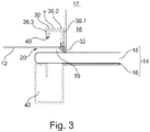
- FIG. 3 a further embodiment of the arrangement of the microwave seal 30 in the edge region 20 is shown.
- FIG. 3 corresponds essentially to the embodiment according to FIG. 2 , in which only the differences are discussed below. Accordingly, the same or functionally identical parts are provided with the same reference numerals.
- the microwave seal 30 is formed by a groove 36.
- the groove 36 not only a straight portion, but a plurality of sections 36.1, 36.2, 36.3, which are each arranged at an angle, in particular right angles to each other.
- the depth T of the groove 36 corresponds to the distance from the rear wall 40 of the groove 36 through the sections 36.1, 36.2, 36.3 to the mouth of the groove 36 in the gap 19th
- the depth T of the groove 36 corresponds to a quarter of the wavelength of the microwave radiation used in the cooking appliance 10.
- the depth T of the groove 36 is selected, for example, such that the microwave seal 30 covers the widest possible bandwidth of the microwave radiation used in the cooking appliance 10.
- the cooking chamber seal 32 is in the embodiment according to FIG. 3 arranged in the groove 36 itself. In this way, can be dispensed with a recess for the cooking chamber seal 32 and thus the required space for the microwave seal 30 and the cooking chamber seal 32 are reduced.
- the cooking chamber seal 32 also assumes the function of the cover 38 and protects the groove 36 from contamination.
- the arrangement of the cooking chamber seal 32 in the groove 36 is considered in this context beyond the usual meaning of the word "between” as well as between the cooking chamber 17 and the microwave seal 30.
- a further microwave trap 42 may be provided in the cooking chamber door 14.
- the further microwave trap 42 is realized for example by a groove in the perforated plate 16 and is covered by the disc 15.
- the microwave trap 42 is also a ⁇ / 4 trap, but for a different wavelength of microwave radiation than the microwave seal 30 of the housing 12.
- the microwave trap 42 and the microwave seal 30 are designed, it is possible to greatly reduce the leakage of microwave radiation from the cooking appliance 10, even if a broadband microwave source is used, ie the microwave radiation in the cooking chamber 17 different , Partially significantly different wavelengths.
- the groove 36 in the embodiment according to FIG. 2 also be formed of several sections 36.1, 36.2, 36.3.
Landscapes
- Physics & Mathematics (AREA)
- Electromagnetism (AREA)
- Electric Ovens (AREA)
Description
- Die Erfindung betrifft ein Gargerät mit einer Mikrowellendichtung.
- Gargeräte, die eine Mikrowellenquelle zum Garen von Gargütern aufweisen sind hinreichend bekannt. Beim Betrieb der Mikrowellenquelle im Gargerät gilt es zu vermeiden, dass Mikrowellenstrahlung aus dem Gargerät austritt, um Strahlungsbelastungen der Benutzer des Gargerätes möglichst gering zu halten. Hierzu sind solche Gargeräte üblicherweise mit Mikrowellendichtungen versehen.
- Insbesondere der Abdichtung der Beschickungsöffnung des Garraums gegenüber Mikrowellenstrahlung kommt große Bedeutung zu, weil die Beschickungsöffnung die größte Öffnung im Gehäuse des Gargerätes darstellt. Hierzu ist es bekannt, eine Mikrowellenfalle, beispielsweise eine λ/4-Falle, in der Garraumtür hinter einer Glasscheibe vorzusehen. Dadurch wird die Komplexität und Dicke der Garraumtüre jedoch vergrößert. Wird die Mikrowellendichtung am Gehäuse angeordnet, so ist sie nicht durch die Glasscheibe abgedeckt und verschmutzt rasch.
- Die
EP 0 374 520 offenbart ein Gargerät mit einem Garraum und einer Garraumtüre sowie einer Garraumdichtung und einer Mikrowellendichtung, wobei der Garraum durch eine Garraumwand begrenzt wird. Der vorderste Teil des Garraums wird durch einen Außenkasten begrenzt, d.h. der Außenkasten ragt durch die Beschickungsöffnung in den Garraum hinein. - Die
EP 2 541 151 A1 zeigt ein Gargerät mit einem Gehäuse, einem Garraum und einer Garraumtür, wobei in der Garraumtür eine Mikrowellenfalle vorgesehen ist. In der Öffnung der Mikrowellenfalle zum Spalt zwischen Gehäuse und Garraumtür hin ist eine Garraumdichtung vorgesehen, die also zwischen Mikrowellendichtung und Garraum angeordnet ist. - Es ist Aufgabe der Erfindung, ein Gargerät mit einer Mikrowellendichtung bereitzustellen, die sowohl vor Verschmutzung geschützt ist als eine einfache und platzsparende Konstruktion der Garraumtüre ermöglicht.
- Die Aufgabe wird gelöst durch ein Gargerät gemäß Anspruch 1. Dabei wird unter dem Begriff "zwischen" auch verstanden, dass die Garraumdichtung zumindest teilweise in die Mikrowellendichtung hineinragt. Durch die Anordnung der Garraumdichtung am Gehäuse wird die Komplexität der Garraumtüre verringert. Gleichzeitig wird durch die Position der Garraumdichtung zwischen der Mikrowellendichtung und dem Garraum eine rasche Verschmutzung der Mikrowellendichtung verhindert, ohne dabei die Funktion der Mikrowellendichtung zu beeinträchtigen. Auch wird ein Austritt von Mikrowellenstrahlung durch die Beschickungsöffnung wirksam verhindert.
- Beispielsweise weist das Gehäuse einen Innenkasten und einen Außenkasten auf, wobei der Innenkasten den Garraum begrenzt und der Randbereich größtenteils am Außenkasten vorgesehen ist, sodass durch die Ausbildung der Mikrowellendichtung am Gehäuse der Garraum nicht verändert werden muss.
- In einer Ausführungsvariante ist die Mikrowellendichtung eine λ/4-Falle, wodurch eine einfache und bewährte Methode zur Verhinderung eines Austritts von Mikrowellenstrahlung gewählt ist.
- In einer Ausgestaltung der Erfindung ist die Mikrowellendichtung einstückig mit dem Randbereich ausgeführt, wodurch eine besonders einfache Ausgestaltung der Mikrowellendichtung ermöglicht wird.
- Die Nut kann dabei sowohl nur aus einem geraden Abschnitt bestehen als auch mehrere zueinander in einem Winkel angeordnete Abschnitte aufweisen oder spiralförmig sein.
- Vorzugsweise entspricht die Tiefe der Nut einem Viertel der Wellenlänge der im Gargerät verwendeten Mikrowellenstrahlung. Auf diese Weise wird eine λ/4-Falle realisiert.
- In einer Ausführungsform der Erfindung ist die Garraumdichtung am Gehäuse befestigt, so dass die Komplexität der Garraumtüre weiter verringert wird.
- Die Garraumdichtung kann in der Nut angeordnet sein, wodurch der benötigte Bauraum für die Mikrowellendichtung und die Garraumdichtung verringert wird.
- Beispielsweise ist die Mikrowellendichtung auf der vom Garraum abgewandten Seite der Garraumdichtung angeordnet, wodurch eine rasche Verschmutzung der Mikrowellendichtung auf einfache Weise verhindert wird.
- In einer Ausführungsvariante wird die Nut durch eine für Mikrowellenstrahlung durchlässige Abdeckung verschlossen, wobei die Außenfläche der Abdeckung mit dem Randbereich eine Ebene bildet. Auf diese Weise wird eine Verschmutzung der Mikrowellendichtung verhindert und die Reinigung des Gargerätes durch die Ausbildung einer ebenen Fläche mit dem Randbereich vereinfacht.
- In einer Ausgestaltung der Erfindung kann an der Garraumtür eine weitere Mikrowellenfalle vorgesehen sein. Durch die weitere Mikrowellenfalle in der Garraumtür ist es möglich, den Austritt von Mikrowellenstrahlung aus dem Garraum weiter zu verringern, da die weitere Mikrowellenfalle eine andere Resonanzfrequenz als die Mikrowellendichtung des Gehäuses aufweisen kann. Auch ist es denkbar, dass aufgrund der Mikrowellendichtung im Gehäuse die Mikrowellenfalle in der Garraumtüre kleiner und einfacher ausgeführt sein kann, wodurch die Komplexität der Garraumtüre gering bleibt.
- Weitere Merkmale und Vorteile der Erfindung ergeben sich aus der nachfolgenden Beschreibung sowie aus den beigefügten Zeichnungen, auf die Bezug genommen wird. In den Zeichnungen zeigen:
-
Figur 1 eine schematische Perspektivansicht eines erfindungsgemäßen Gargeräts, -
Figur 2 einen Teil des erfindungsgemäßen Gargeräts nachFigur 1 im Schnitt, und -
Figur 3 einen Teil einer weiteren Ausführungsform eines erfindungsgemäßen Gargeräts im Schnitt. - In
Figur 1 ist schematisch ein Gargerät 10 in perspektivischer Ansicht dargestellt. Das Gargerät 10 weist ein Gehäuse 12 und eine Garraumtüre 14 auf. - Die Garraumtüre 14 weist eine Scheibe 15, beispielsweise aus Glas, und ein Lochblech 16 auf.
- Das Gehäuse 12 begrenzt einen Garraum 17, der durch eine Beschickungsöffnung 18 im Gehäuse 12 von außerhalb des Gargeräts 10 zugänglich ist.
- Die Beschickungsöffnung 18 wird von der Garraumtüre 14, wenn diese geschlossen ist, vollständig abgedeckt.
- Zudem ist bei geschlossener Garraumtüre 14 ein Spalt 19 zwischen Garraumtüre 14 und dem Gehäuse 12 vorgesehen.
- Am Gehäuse 12 schließt sich an die Beschickungsöffnung 18 ein Randbereich 20 an, der ebenfalls vollständig von der Garraumtüre 14 verschlossen wird, wenn diese geschlossen ist.
- Folglich entspricht die gehäuseseitige Begrenzung des Spaltes 19 dem Randbereich 20.
- In
Figur 2 ist ein Ausschnitt des Gargeräts 10 um einen Teil des Randbereiches 20 in einer Draufsicht im Schnitt dargestellt. - Das Gehäuse 12 weist einen Innenkasten 22 und einen mit dem Innenkasten 22 verbundenen Außenkasten 24 auf.
- Der Innenkasten 22 begrenzt den Garraum 17, wobei der Randbereich 20 größtenteils am Außenkasten 24 vorgesehen ist und von der Garraumtüre 14 (in geschlossener Position) vollständig abgedeckt wird.
- Im Randbereich 20 ist sowohl eine Mikrowellendichtung 30 als auch eine Garraumdichtung 32 vorgesehen.
- Die Garraumdichtung 32 ist zum Beispiel aus einem Material hergestellt, dass für die im Gargerät 10 verwendete Mikrowellenstrahlung durchlässig ist.
- Zudem kann die Garraumdichtung 32 in einer Ausnehmung 34 vorgesehen sein, die im Außenkasten 24 im Randbereich 20 ausgebildet ist.
- Auch ist es denkbar, dass die Ausnehmung 34 auf der der Beschickungsöffnung 18 abgewandten Seite durch den Außenkasten 24 und auf der der Beschickungsöffnung 18 zugewandten Seite durch den Innenkasten 22 begrenzt ist.
- Die Garraumdichtung 32 erstreckt sich in den Spalt 19 und liegt, wenn die Garraumtüre 14 geschlossen ist, an dieser an.
- Die Garraumdichtung 32 kann am Gehäuse 12, insbesondere in der Ausnehmung 34, befestigt sein.
- Auch kann die Garraumdichtung 32 so angeordnet sein, dass der Teil der Garraumdichtung 32, der in den Spalt 19 hineinragt, bündig mit dem Abschnitt des Innenkastens 22 anschließt, der die Beschickungsöffnung 18 begrenzt.
- Auf der vom Garraum 17 abgewandten Seite der Garraumdichtung 32 ist der Randbereich 20 mit einer Mikrowellendichtung 30 versehen.
- Die Mikrowellendichtung 30 ist als Nut 36 im Randbereich ausgebildet, insbesondere im Außenkasten 24.
- Auch kann die Nut 36 einstückig mit dem Außenkasten 24 ausgeführt sein.
- Die Nut 36 und somit die Mikrowellendichtung 30 umgibt den Umfang der Beschickungsöffnung 18 vollständig.
- In der in
Figur 2 gezeigten Ausführungsform erstreckt sich die Nut 36 senkrecht vom Spalt 19 in Richtung des Innenkastens 22. - Die Nut hat dabei eine Tiefe T, die einem Viertel der Wellenlänge der im Gargerät verwendeten Mikrowellenstrahlung entspricht.
- Wird im Gargerät 10 Mikrowellenstrahlung mit mehreren Wellenlängen verwendet, so ist die Tiefe T der Nut 36 beispielsweise derart gewählt, dass die Mikrowellendichtung 30 eine möglichst große Bandbreite der im Gargerät 10 verwendeten Mikrowellenstrahlung abdeckt.
- Die Mikrowellendichtung 30 kann somit eine λ/4-Falle sein.
- Zudem kann die Nut 36 durch eine Abdeckung 38 verschlossen werden, die für Mikrowellenstrahlung durchlässig ist.
- Dabei kann die Außenfläche der Abdeckung 38 mit dem Randbereich 20 eine Ebene bilden, so dass die Reinigung des Gargerätes 10 einfach möglich ist.
- Durch die Mikrowellendichtung 30 wird Mikrowellenstrahlung, die durch den Spalt 19 aus dem Garraum 17 propagiert, effektiv daran gehindert, dass sie aus dem Gargerät 10 vollständig austritt.
- Hingegen dient die Garraumdichtung 32 zur thermischen sowie fluiddichten Abdichtung des Garraums 17, um Energieverluste der Garraumatmosphäre durch Konvektion zu vermeiden. Außerdem verhindert die Anordnung der Garraumdichtung 32 zwischen dem Garraum 17 und der Mikrowellendichtung 30, dass die Mikrowellendichtung 30 während des Betriebs des Gargerätes 10 der Garraumatmosphäre ausgesetzt ist und verschmutzt.
- In
Figur 3 ist eine weitere Ausführungsform der Anordnung der Mikrowellendichtung 30 im Randbereich 20 dargestellt. - Die in
Figur 3 gezeigte Ausführungsform entspricht im Wesentlichen der Ausführungsform nachFigur 2 , wobei im Folgenden nur auf die Unterschiede eingegangen wird. Entsprechend werden gleiche oder funktionsgleiche Teile mit denselben Bezugszeichen versehen. - Auch in der Ausführungsform nach
Figur 3 wird die Mikrowellendichtung 30 durch eine Nut 36 gebildet. Im Gegensatz zur Ausführungsform nachFigur 2 weist die Nut 36 jedoch nicht nur einen geraden Abschnitt, sondern mehrere Abschnitte 36.1, 36.2, 36.3 auf, die jeweils in einem Winkel, insbesondere rechten Winkeln, zueinander angeordnet sind. - Die Tiefe T der Nut 36 entspricht dabei dem Abstand von der Rückwand 40 der Nut 36 durch die Abschnitte 36.1, 36.2, 36.3 zur Mündung der Nut 36 in den Spalt 19.
- Auch in der Ausführungsform nach
Figur 3 entspricht die Tiefe T der Nut 36 einem Viertel der Wellenlänge der im Gargerät 10 verwendeten Mikrowellenstrahlung. - Wird im Gargerät 10 Mikrowellenstrahlung mit mehreren Wellenlängen verwendet, so ist die Tiefe T der Nut 36 zum Beispiel derart gewählt, dass die Mikrowellendichtung 30 eine möglichst große Bandbreite der im Gargerät 10 verwendeten Mikrowellenstrahlung abdeckt.
- Die Garraumdichtung 32 ist in der Ausführungsform nach
Figur 3 in der Nut 36 selbst angeordnet. Auf diese Weise kann auf eine Ausnehmung für die Garraumdichtung 32 verzichtet und somit der benötigte Bauraum für die Mikrowellendichtung 30 und die Garraumdichtung 32 verringert werden. - Auch übernimmt die Garraumdichtung 32 die Funktion der Abdeckung 38 und schützt die Nut 36 vor Verunreinigungen.
- Die Anordnung der Garraumdichtung 32 in der Nut 36 wird in diesem Zusammenhang über den üblichen Sinn des Wortes "zwischen" hinausgehend auch als zwischen dem Garraum 17 und der Mikrowellendichtung 30 angesehen.
- Weiterhin kann in der Garraumtüre 14 eine weitere Mikrowellenfalle 42 vorgesehen sein.
- Die weitere Mikrowellenfalle 42 ist beispielsweise durch eine Nut im Lochblech 16 realisiert und wird durch die Scheibe 15 abgedeckt.
- Beispielsweise ist die Mikrowellenfalle 42 ebenfalls eine λ/4-Falle, jedoch für eine andere Wellenlänge der Mikrowellenstrahlung als die Mikrowellendichtung 30 des Gehäuses 12.
- Durch die geschickte Wahl der Wellenlängen, auf die die Mikrowellenfalle 42 und die Mikrowellendichtung 30 ausgelegt sind, ist es möglich, das Austreten von Mikrowellenstrahlung aus dem Gargerät 10 stark zu verringern, selbst wenn eine breitbandige Mikrowellenquelle verwendet wird, also die Mikrowellenstrahlung im Garraum 17 verschiedenen, teilweise deutlich unterschiedliche Wellenlängen aufweist.
- Selbstverständlich sind die Merkmale der beiden beispielhaft gezeigten Ausführungsformen beliebig miteinander kombinierbar, insbesondere kann die Nut 36 in der Ausführungsform nach
Figur 2 ebenfalls aus mehreren Abschnitten 36.1, 36.2, 36.3 ausgebildet sein.
Claims (10)
- Gargerät mit einem Gehäuse (12), das einen Garraum (17) aufweist, und einer Garraumtür (14), die eine Beschickungsöffnung (18) des Gehäuses (12) verschließen kann, wobei ein Randbereich (20) des Gehäuses (12) sich an die Beschickungsöffnung (18) anschließt, der von der Garraumtür (14) im geschlossenen Zustand vollständig abgedeckt wird, wobei der Randbereich (20) des Gehäuses (12) mit einer Mikrowellendichtung (30) versehen ist und wobei am Randbereich (20) eine Garraumdichtung (32) zwischen der Mikrowellendichtung (30) und dem Garraum (17) angeordnet ist, wobei die Mikrowellendichtung (30) den Umfang der Beschickungsöffnung (18) vollständig umgibt, so dass ein Austritt von Mikrowellenstrahlung durch die Beschickungsöffnung (18) wirksam verhindert wird, dadurch gekennzeichnet, dass die Mikrowellendichtung (30) als Nut (36) im Randbereich (20) ausgeführt ist.
- Gargerät nach Anspruch 1, dadurch gekennzeichnet, dass das Gehäuse (12) einen Innenkasten (22) und einen Außenkasten (24) aufweist, wobei der Innenkasten (22) den Garraum (17) begrenzt und der Randbereich (20) größtenteils am Außenkasten (24) vorgesehen ist.
- Gargerät nach Anspruch 1 oder 2, dadurch gekennzeichnet, dass die Mikrowellendichtung (30) eine λ/4-Falle ist.
- Gargerät nach einem der vorhergehenden Ansprüche, dadurch gekennzeichnet, dass die Mikrowellendichtung (30) einstückig mit dem Randbereich (20) ausgeführt ist.
- Gargerät nach Anspruch 4, dadurch gekennzeichnet, dass die Tiefe (T) der Nut (36) einem Viertel der Wellenlänge der im Gargerät (10) verwendeten Mikrowellenstrahlung entspricht.
- Gargerät nach einem der vorhergehenden Ansprüche, dadurch gekennzeichnet, dass die Garraumdichtung (32) am Gehäuse (12) befestigt ist.
- Gargerät nach einem der vorhergehenden Ansprüche, dadurch gekennzeichnet, dass die Garraumdichtung (32) in der Nut (36) angeordnet ist.
- Gargerät nach einem der Ansprüche 1 bis 6, dadurch gekennzeichnet, dass die Mikrowellendichtung (30) auf der vom Garraum (17) abgewandten Seite der Garraumdichtung (32) angeordnet ist.
- Gargerät nach einem der vorhergehenden Ansprüche, dadurch gekennzeichnet, dass die Nut (36) durch eine für Mikrowellenstrahlung durchlässige Abdeckung (38) verschlossen wird, wobei die Außenfläche der Abdeckung (38) mit dem Randbereich (20) eine Ebene bildet.
- Gargerät nach einem der vorhergehenden Ansprüche, dadurch gekennzeichnet, dass an der Garraumtür (14) eine weitere Mikrowellenfalle (42) vorgesehen ist.
Applications Claiming Priority (1)
| Application Number | Priority Date | Filing Date | Title |
|---|---|---|---|
| DE102014107581.1A DE102014107581A1 (de) | 2014-05-28 | 2014-05-28 | Gargerät mit Mikrowellendichtung |
Publications (2)
| Publication Number | Publication Date |
|---|---|
| EP2950617A1 EP2950617A1 (de) | 2015-12-02 |
| EP2950617B1 true EP2950617B1 (de) | 2019-09-18 |
Family
ID=53396197
Family Applications (1)
| Application Number | Title | Priority Date | Filing Date |
|---|---|---|---|
| EP15168891.8A Active EP2950617B1 (de) | 2014-05-28 | 2015-05-22 | Gargerät mit mikrowellendichtung |
Country Status (2)
| Country | Link |
|---|---|
| EP (1) | EP2950617B1 (de) |
| DE (1) | DE102014107581A1 (de) |
Families Citing this family (3)
| Publication number | Priority date | Publication date | Assignee | Title |
|---|---|---|---|---|
| IT202000017299A1 (it) * | 2020-07-16 | 2022-01-16 | Smeg Spa | Forno per vivande |
| DE102023118291B3 (de) | 2023-07-11 | 2024-12-05 | Rational Aktiengesellschaft | Kombinationsgargerät mit Ringmodenunterdrücker |
| DE102023118290B4 (de) | 2023-07-11 | 2025-01-30 | Rational Aktiengesellschaft | Kombinationsgargerät mit Ringmodenunterdrücker |
Citations (2)
| Publication number | Priority date | Publication date | Assignee | Title |
|---|---|---|---|---|
| DE2848658A1 (de) * | 1977-11-25 | 1979-05-31 | Raytheon Co | Mikrowellenherd oder -ofen |
| DE102006042992A1 (de) * | 2006-09-13 | 2008-04-03 | BSH Bosch und Siemens Hausgeräte GmbH | Mikrowellenfalle |
Family Cites Families (3)
| Publication number | Priority date | Publication date | Assignee | Title |
|---|---|---|---|---|
| IT1225856B (it) * | 1988-12-19 | 1990-12-07 | Zanussi A Spa Industrie | Forno a microonde dotato di dispositivo per la schermatura delle microonde |
| JP2011174669A (ja) * | 2010-02-25 | 2011-09-08 | Panasonic Corp | 高周波加熱調理装置 |
| DE102012112805A1 (de) * | 2012-12-20 | 2014-06-26 | Miele & Cie. Kg | Gargerät |
-
2014
- 2014-05-28 DE DE102014107581.1A patent/DE102014107581A1/de not_active Withdrawn
-
2015
- 2015-05-22 EP EP15168891.8A patent/EP2950617B1/de active Active
Patent Citations (2)
| Publication number | Priority date | Publication date | Assignee | Title |
|---|---|---|---|---|
| DE2848658A1 (de) * | 1977-11-25 | 1979-05-31 | Raytheon Co | Mikrowellenherd oder -ofen |
| DE102006042992A1 (de) * | 2006-09-13 | 2008-04-03 | BSH Bosch und Siemens Hausgeräte GmbH | Mikrowellenfalle |
Also Published As
| Publication number | Publication date |
|---|---|
| DE102014107581A1 (de) | 2015-12-03 |
| EP2950617A1 (de) | 2015-12-02 |
Similar Documents
| Publication | Publication Date | Title |
|---|---|---|
| EP2950617A1 (de) | Gargerät mit mikrowellendichtung | |
| EP2747515A1 (de) | Gargerät | |
| EP2610557A1 (de) | Backofen mit Unterhitze und Heißluft | |
| EP2991448B1 (de) | Gargerät | |
| DE3607557C2 (de) | ||
| DE102018121502A1 (de) | Gargerät, umfassend einen ersten und einen zweiten Garraum | |
| DE2109630B2 (de) | Hochfrequenzofen | |
| DE102006001293B4 (de) | Gargerät und Verfahren zum Betreiben eines Gargeräts | |
| DE102013106623B4 (de) | Gargerät mit Abweiser | |
| CH697480B1 (de) | Garofen. | |
| DE102018128475A1 (de) | Küchengerät | |
| DE102014116432B4 (de) | Dichtung für ein Gargerät sowie Gargerät | |
| DE102014118166A1 (de) | Gargerät | |
| DE102006042992A1 (de) | Mikrowellenfalle | |
| DE102014112592A1 (de) | Gargerät | |
| EP4076095B1 (de) | Verschlussvorrichtung für einen druckbehälter, druckbehälter und verwendung der verschlussvorrichtung | |
| DE102023118291B3 (de) | Kombinationsgargerät mit Ringmodenunterdrücker | |
| WO1997014270A1 (de) | Mikrowellenofen, insbesondere für ein labor | |
| BE1032518A1 (de) | Gareinrichtung | |
| DE102023130337B3 (de) | Gargerät mit Mikrowellenfunktion und Mikrowellenfallen | |
| DE202026100181U1 (de) | Dampfgargerät | |
| DE3027839C2 (de) | Mikrowellengerät | |
| DE1957928C3 (de) | Hochfrequenzdichte Türe für Mikrowellenofen | |
| DE102015100824A1 (de) | Tür sowie Gargerät | |
| DE102014114292A1 (de) | Lüfterantriebswelle sowie Gargerät |
Legal Events
| Date | Code | Title | Description |
|---|---|---|---|
| AK | Designated contracting states |
Kind code of ref document: A1 Designated state(s): AL AT BE BG CH CY CZ DE DK EE ES FI FR GB GR HR HU IE IS IT LI LT LU LV MC MK MT NL NO PL PT RO RS SE SI SK SM TR |
|
| AX | Request for extension of the european patent |
Extension state: BA ME |
|
| PUAI | Public reference made under article 153(3) epc to a published international application that has entered the european phase |
Free format text: ORIGINAL CODE: 0009012 |
|
| 17P | Request for examination filed |
Effective date: 20160524 |
|
| RBV | Designated contracting states (corrected) |
Designated state(s): AL AT BE BG CH CY CZ DE DK EE ES FI FR GB GR HR HU IE IS IT LI LT LU LV MC MK MT NL NO PL PT RO RS SE SI SK SM TR |
|
| RAP1 | Party data changed (applicant data changed or rights of an application transferred) |
Owner name: RATIONAL AKTIENGESELLSCHAFT |
|
| GRAP | Despatch of communication of intention to grant a patent |
Free format text: ORIGINAL CODE: EPIDOSNIGR1 |
|
| STAA | Information on the status of an ep patent application or granted ep patent |
Free format text: STATUS: GRANT OF PATENT IS INTENDED |
|
| INTG | Intention to grant announced |
Effective date: 20190408 |
|
| RIN1 | Information on inventor provided before grant (corrected) |
Inventor name: HERNER, MICHAEL Inventor name: TILS, THOMAS Inventor name: PRINZING, MICHAEL Inventor name: KLUKAS, RALF |
|
| GRAS | Grant fee paid |
Free format text: ORIGINAL CODE: EPIDOSNIGR3 |
|
| GRAA | (expected) grant |
Free format text: ORIGINAL CODE: 0009210 |
|
| STAA | Information on the status of an ep patent application or granted ep patent |
Free format text: STATUS: THE PATENT HAS BEEN GRANTED |
|
| AK | Designated contracting states |
Kind code of ref document: B1 Designated state(s): AL AT BE BG CH CY CZ DE DK EE ES FI FR GB GR HR HU IE IS IT LI LT LU LV MC MK MT NL NO PL PT RO RS SE SI SK SM TR |
|
| REG | Reference to a national code |
Ref country code: GB Ref legal event code: FG4D Free format text: NOT ENGLISH |
|
| REG | Reference to a national code |
Ref country code: CH Ref legal event code: EP |
|
| REG | Reference to a national code |
Ref country code: DE Ref legal event code: R096 Ref document number: 502015010376 Country of ref document: DE |
|
| REG | Reference to a national code |
Ref country code: AT Ref legal event code: REF Ref document number: 1182852 Country of ref document: AT Kind code of ref document: T Effective date: 20191015 |
|
| REG | Reference to a national code |
Ref country code: IE Ref legal event code: FG4D Free format text: LANGUAGE OF EP DOCUMENT: GERMAN |
|
| REG | Reference to a national code |
Ref country code: NL Ref legal event code: MP Effective date: 20190918 |
|
| PG25 | Lapsed in a contracting state [announced via postgrant information from national office to epo] |
Ref country code: HR Free format text: LAPSE BECAUSE OF FAILURE TO SUBMIT A TRANSLATION OF THE DESCRIPTION OR TO PAY THE FEE WITHIN THE PRESCRIBED TIME-LIMIT Effective date: 20190918 Ref country code: SE Free format text: LAPSE BECAUSE OF FAILURE TO SUBMIT A TRANSLATION OF THE DESCRIPTION OR TO PAY THE FEE WITHIN THE PRESCRIBED TIME-LIMIT Effective date: 20190918 Ref country code: BG Free format text: LAPSE BECAUSE OF FAILURE TO SUBMIT A TRANSLATION OF THE DESCRIPTION OR TO PAY THE FEE WITHIN THE PRESCRIBED TIME-LIMIT Effective date: 20191218 Ref country code: LT Free format text: LAPSE BECAUSE OF FAILURE TO SUBMIT A TRANSLATION OF THE DESCRIPTION OR TO PAY THE FEE WITHIN THE PRESCRIBED TIME-LIMIT Effective date: 20190918 Ref country code: FI Free format text: LAPSE BECAUSE OF FAILURE TO SUBMIT A TRANSLATION OF THE DESCRIPTION OR TO PAY THE FEE WITHIN THE PRESCRIBED TIME-LIMIT Effective date: 20190918 Ref country code: NO Free format text: LAPSE BECAUSE OF FAILURE TO SUBMIT A TRANSLATION OF THE DESCRIPTION OR TO PAY THE FEE WITHIN THE PRESCRIBED TIME-LIMIT Effective date: 20191218 |
|
| REG | Reference to a national code |
Ref country code: LT Ref legal event code: MG4D |
|
| PG25 | Lapsed in a contracting state [announced via postgrant information from national office to epo] |
Ref country code: RS Free format text: LAPSE BECAUSE OF FAILURE TO SUBMIT A TRANSLATION OF THE DESCRIPTION OR TO PAY THE FEE WITHIN THE PRESCRIBED TIME-LIMIT Effective date: 20190918 Ref country code: GR Free format text: LAPSE BECAUSE OF FAILURE TO SUBMIT A TRANSLATION OF THE DESCRIPTION OR TO PAY THE FEE WITHIN THE PRESCRIBED TIME-LIMIT Effective date: 20191219 Ref country code: AL Free format text: LAPSE BECAUSE OF FAILURE TO SUBMIT A TRANSLATION OF THE DESCRIPTION OR TO PAY THE FEE WITHIN THE PRESCRIBED TIME-LIMIT Effective date: 20190918 Ref country code: LV Free format text: LAPSE BECAUSE OF FAILURE TO SUBMIT A TRANSLATION OF THE DESCRIPTION OR TO PAY THE FEE WITHIN THE PRESCRIBED TIME-LIMIT Effective date: 20190918 |
|
| PG25 | Lapsed in a contracting state [announced via postgrant information from national office to epo] |
Ref country code: ES Free format text: LAPSE BECAUSE OF FAILURE TO SUBMIT A TRANSLATION OF THE DESCRIPTION OR TO PAY THE FEE WITHIN THE PRESCRIBED TIME-LIMIT Effective date: 20190918 Ref country code: PT Free format text: LAPSE BECAUSE OF FAILURE TO SUBMIT A TRANSLATION OF THE DESCRIPTION OR TO PAY THE FEE WITHIN THE PRESCRIBED TIME-LIMIT Effective date: 20200120 Ref country code: NL Free format text: LAPSE BECAUSE OF FAILURE TO SUBMIT A TRANSLATION OF THE DESCRIPTION OR TO PAY THE FEE WITHIN THE PRESCRIBED TIME-LIMIT Effective date: 20190918 Ref country code: EE Free format text: LAPSE BECAUSE OF FAILURE TO SUBMIT A TRANSLATION OF THE DESCRIPTION OR TO PAY THE FEE WITHIN THE PRESCRIBED TIME-LIMIT Effective date: 20190918 Ref country code: IT Free format text: LAPSE BECAUSE OF FAILURE TO SUBMIT A TRANSLATION OF THE DESCRIPTION OR TO PAY THE FEE WITHIN THE PRESCRIBED TIME-LIMIT Effective date: 20190918 Ref country code: RO Free format text: LAPSE BECAUSE OF FAILURE TO SUBMIT A TRANSLATION OF THE DESCRIPTION OR TO PAY THE FEE WITHIN THE PRESCRIBED TIME-LIMIT Effective date: 20190918 Ref country code: PL Free format text: LAPSE BECAUSE OF FAILURE TO SUBMIT A TRANSLATION OF THE DESCRIPTION OR TO PAY THE FEE WITHIN THE PRESCRIBED TIME-LIMIT Effective date: 20190918 |
|
| PG25 | Lapsed in a contracting state [announced via postgrant information from national office to epo] |
Ref country code: SM Free format text: LAPSE BECAUSE OF FAILURE TO SUBMIT A TRANSLATION OF THE DESCRIPTION OR TO PAY THE FEE WITHIN THE PRESCRIBED TIME-LIMIT Effective date: 20190918 Ref country code: IS Free format text: LAPSE BECAUSE OF FAILURE TO SUBMIT A TRANSLATION OF THE DESCRIPTION OR TO PAY THE FEE WITHIN THE PRESCRIBED TIME-LIMIT Effective date: 20200224 Ref country code: SK Free format text: LAPSE BECAUSE OF FAILURE TO SUBMIT A TRANSLATION OF THE DESCRIPTION OR TO PAY THE FEE WITHIN THE PRESCRIBED TIME-LIMIT Effective date: 20190918 Ref country code: CZ Free format text: LAPSE BECAUSE OF FAILURE TO SUBMIT A TRANSLATION OF THE DESCRIPTION OR TO PAY THE FEE WITHIN THE PRESCRIBED TIME-LIMIT Effective date: 20190918 |
|
| REG | Reference to a national code |
Ref country code: DE Ref legal event code: R097 Ref document number: 502015010376 Country of ref document: DE |
|
| PLBE | No opposition filed within time limit |
Free format text: ORIGINAL CODE: 0009261 |
|
| STAA | Information on the status of an ep patent application or granted ep patent |
Free format text: STATUS: NO OPPOSITION FILED WITHIN TIME LIMIT |
|
| PG2D | Information on lapse in contracting state deleted |
Ref country code: IS |
|
| PG25 | Lapsed in a contracting state [announced via postgrant information from national office to epo] |
Ref country code: DK Free format text: LAPSE BECAUSE OF FAILURE TO SUBMIT A TRANSLATION OF THE DESCRIPTION OR TO PAY THE FEE WITHIN THE PRESCRIBED TIME-LIMIT Effective date: 20190918 Ref country code: IS Free format text: LAPSE BECAUSE OF FAILURE TO SUBMIT A TRANSLATION OF THE DESCRIPTION OR TO PAY THE FEE WITHIN THE PRESCRIBED TIME-LIMIT Effective date: 20200119 |
|
| 26N | No opposition filed |
Effective date: 20200619 |
|
| PG25 | Lapsed in a contracting state [announced via postgrant information from national office to epo] |
Ref country code: SI Free format text: LAPSE BECAUSE OF FAILURE TO SUBMIT A TRANSLATION OF THE DESCRIPTION OR TO PAY THE FEE WITHIN THE PRESCRIBED TIME-LIMIT Effective date: 20190918 |
|
| PG25 | Lapsed in a contracting state [announced via postgrant information from national office to epo] |
Ref country code: CH Free format text: LAPSE BECAUSE OF NON-PAYMENT OF DUE FEES Effective date: 20200531 Ref country code: LI Free format text: LAPSE BECAUSE OF NON-PAYMENT OF DUE FEES Effective date: 20200531 Ref country code: MC Free format text: LAPSE BECAUSE OF FAILURE TO SUBMIT A TRANSLATION OF THE DESCRIPTION OR TO PAY THE FEE WITHIN THE PRESCRIBED TIME-LIMIT Effective date: 20190918 |
|
| REG | Reference to a national code |
Ref country code: BE Ref legal event code: MM Effective date: 20200531 |
|
| GBPC | Gb: european patent ceased through non-payment of renewal fee |
Effective date: 20200522 |
|
| PG25 | Lapsed in a contracting state [announced via postgrant information from national office to epo] |
Ref country code: LU Free format text: LAPSE BECAUSE OF NON-PAYMENT OF DUE FEES Effective date: 20200522 |
|
| PG25 | Lapsed in a contracting state [announced via postgrant information from national office to epo] |
Ref country code: GB Free format text: LAPSE BECAUSE OF NON-PAYMENT OF DUE FEES Effective date: 20200522 Ref country code: IE Free format text: LAPSE BECAUSE OF NON-PAYMENT OF DUE FEES Effective date: 20200522 |
|
| PG25 | Lapsed in a contracting state [announced via postgrant information from national office to epo] |
Ref country code: BE Free format text: LAPSE BECAUSE OF NON-PAYMENT OF DUE FEES Effective date: 20200531 |
|
| REG | Reference to a national code |
Ref country code: AT Ref legal event code: MM01 Ref document number: 1182852 Country of ref document: AT Kind code of ref document: T Effective date: 20200522 |
|
| PG25 | Lapsed in a contracting state [announced via postgrant information from national office to epo] |
Ref country code: AT Free format text: LAPSE BECAUSE OF NON-PAYMENT OF DUE FEES Effective date: 20200522 |
|
| PG25 | Lapsed in a contracting state [announced via postgrant information from national office to epo] |
Ref country code: TR Free format text: LAPSE BECAUSE OF FAILURE TO SUBMIT A TRANSLATION OF THE DESCRIPTION OR TO PAY THE FEE WITHIN THE PRESCRIBED TIME-LIMIT Effective date: 20190918 Ref country code: MT Free format text: LAPSE BECAUSE OF FAILURE TO SUBMIT A TRANSLATION OF THE DESCRIPTION OR TO PAY THE FEE WITHIN THE PRESCRIBED TIME-LIMIT Effective date: 20190918 Ref country code: CY Free format text: LAPSE BECAUSE OF FAILURE TO SUBMIT A TRANSLATION OF THE DESCRIPTION OR TO PAY THE FEE WITHIN THE PRESCRIBED TIME-LIMIT Effective date: 20190918 |
|
| PG25 | Lapsed in a contracting state [announced via postgrant information from national office to epo] |
Ref country code: MK Free format text: LAPSE BECAUSE OF FAILURE TO SUBMIT A TRANSLATION OF THE DESCRIPTION OR TO PAY THE FEE WITHIN THE PRESCRIBED TIME-LIMIT Effective date: 20190918 |
|
| P01 | Opt-out of the competence of the unified patent court (upc) registered |
Effective date: 20230522 |
|
| PGFP | Annual fee paid to national office [announced via postgrant information from national office to epo] |
Ref country code: DE Payment date: 20250519 Year of fee payment: 11 |
|
| PGFP | Annual fee paid to national office [announced via postgrant information from national office to epo] |
Ref country code: FR Payment date: 20250523 Year of fee payment: 11 |