EP2950271A2 - Verfahren und vorrichtung zur tiefenbildgebung - Google Patents
Verfahren und vorrichtung zur tiefenbildgebung Download PDFInfo
- Publication number
- EP2950271A2 EP2950271A2 EP15001558.4A EP15001558A EP2950271A2 EP 2950271 A2 EP2950271 A2 EP 2950271A2 EP 15001558 A EP15001558 A EP 15001558A EP 2950271 A2 EP2950271 A2 EP 2950271A2
- Authority
- EP
- European Patent Office
- Prior art keywords
- distance
- scene
- optical center
- projector
- camera
- Prior art date
- Legal status (The legal status is an assumption and is not a legal conclusion. Google has not performed a legal analysis and makes no representation as to the accuracy of the status listed.)
- Withdrawn
Links
Images

Classifications
-
- G—PHYSICS
- G01—MEASURING; TESTING
- G01B—MEASURING LENGTH, THICKNESS OR SIMILAR LINEAR DIMENSIONS; MEASURING ANGLES; MEASURING AREAS; MEASURING IRREGULARITIES OF SURFACES OR CONTOURS
- G01B11/00—Measuring arrangements characterised by the use of optical techniques
- G01B11/24—Measuring arrangements characterised by the use of optical techniques for measuring contours or curvatures
- G01B11/25—Measuring arrangements characterised by the use of optical techniques for measuring contours or curvatures by projecting a pattern, e.g. one or more lines, moiré fringes on the object
- G01B11/2513—Measuring arrangements characterised by the use of optical techniques for measuring contours or curvatures by projecting a pattern, e.g. one or more lines, moiré fringes on the object with several lines being projected in more than one direction, e.g. grids, patterns
-
- G—PHYSICS
- G06—COMPUTING OR CALCULATING; COUNTING
- G06T—IMAGE DATA PROCESSING OR GENERATION, IN GENERAL
- G06T7/00—Image analysis
- G06T7/50—Depth or shape recovery
- G06T7/521—Depth or shape recovery from laser ranging, e.g. using interferometry; from the projection of structured light
Definitions
- the invention relates to a method and a device for depth imaging, which are based on projecting a matrix of dots on a scene.
- Patent US 6,751,344 B1 discloses a depth imaging of said kind using a pattern formed by a uniform rectangular grid and a reference object in the middle of said grid. A location of a dot within the grid is determined relatively to the reference object whereby determining a mutual correspondence of dots is accelerated. However, a depth determination is not robust precisely due to said reference object and errors may occur.
- the technical problem of the invention is to propose such method and such device for depth imaging a scene that determination of a depth for any point of the scene will be straightforward and a reference point in said determination for any scene point will be unambiguously definable without any need to solve a problem of correspondence between parts of a projected pattern and parts of an image of said pattern.
- the method and device of the invention for depth imaging advantageously make it possible that a depth of any scene point is calculated on the basis of a distance of an image of said scene point from a location in a camera sensor, which is anticipated just for an image of this point at a known scene depth.
- a disclosed method for depth imaging applies projecting a matrix of dots on a scene Sc in a known way.
- a laser whose light is spread by a diffraction element in several light beams, or a projector P ( Fig. 1 ) may be used.
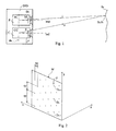
- components of a device DID of the invention for depth imaging are arranged and oriented in the following way.
- the projector P transilluminates a matrix M of the dots D1, D2, ... in a direction of a coordinate axis z, i.e . towards the scene Sc.
- the matrix M e.g. the mask having pinhole at the dot Di ( Figs. 2 and 4 ), allows a light beam i to pass through the pinhole at the dot Di. Said light beam i forms an illuminated ith scene dot at a point ScPi on the scene Sc.
- a sensor S of a camera C an image of the scene as illuminated by the projector P is formed.
- a light beam ir reflected by the scene point ScPi towards the camera C forms an image Ii z of said illuminated scene point ScPi.
- a depth of said scene point ScPi or in other words a value Z of its distance from the camera optical center CC is to be determined.
- the dots Di are distant from each other by a first distance of ap arranged in columns j, which are oriented along a coordinate axis y.
- a lower limit of the value ap of said first distance is determined as fP (d/Z- - d/Z+) in terms of a preset lower limiting distance of Z- of the scene Sc from the camera optical center CC or a projector optical center PC and a preset upper limiting distance of Z+ of the scene Sc from the camera optical center CC or the projector optical center PC, whereat the optical centers CP, CC of the projector P and the camera C, respectively, are distant from each other by a fourth distance of d; fP is a projector focal length.
- the columns j are distant from each other by a second distance of bp in a direction of a coordinate axis x.
- the matrix M is distant from the projector optical center PC being located on the coordinate axis y by the projector focal length of fP; the camera optical center CC is located on the coordinate axis y too.
- Both an optical axis oac of the camera C and an optical axis oap of the projector P are aligned along the coordinate axis z.
- the device DID of the invention for depth imaging is foreseen for imaging scenes Sc between the lower limiting distance of Z- and the upper limiting distance of Z+ ( Fig. 3 ).
- the distance of Z of the point ScPi on the scene Sc from the camera optical center CC or the projector optical center PC or in other words the depth of the scene Sc at said point is to be determined.
- the projected light beam i illuminates the point ScPi on the scene Sc; by the scene Sc at said point ScPi being distant from the camera center CC by a distance of Z-or Z or Z+ light beams ir - or ir or ir + , respectively, are reflected, and in the camera sensor S images Ii Z- or Ii Z or Ii Z- , respectively, are formed.
- a projected light beam i+1 reflected light beams i+1r - or i+1r or i+1r + form images Ii+1 Z- or Ii+1 Z or Ii+1 Z- , respectively, in the camera sensor S.
- a displacement ⁇ i of the image Ii Z of the ith scene dot at the scene point ScPi - at the selected arrangement of the projector P and the camera C said displacement ⁇ i always and exclusively takes place only along the coordinate axis y - is measured from a known location, at which an image Ii Z- of an ith dot in a plane at the lower limiting distance of Z- from the camera optical center CC or the projector optical center PC would be formed, which ith dot in said plane would originate from said matrix dot Di; hereafter said distance of Z - the depth of the ith scene dot - is calculated.
- the sensor S is distant from the camera optical center CC by a camera focal length of fC.
- the distance of Z of any scene point from the x-y plane is calculated by means of interpolation with respect to the distances of Z of the closest illuminated scene dots, which distances have been calculated according to said paraxial approximation (1).
- the matrix M is simply structured; nevertheless, the distance of Z of unlit scene points can be suitably determined too or, more precisely, the unlit parts of the scene Sc can also be suitably reconstructed by means of the method of the invention if the scene Sc is well sampled.
- each two adjacent dots from the adjacent columns in the matrix M are shifted relative to each other in the direction of the coordinate axis y by a third distance of cp.
- the value cp of said third distance is calculated according to an algorithm solving a problem of covering radius on a lattice as a function of the value ap of the first distance and the value bp of the second distance.
- a disclosed device DID for depth imaging in a known way applies a device for projecting a dot matrix on a scene Sc, to which purpose a laser, whose light is spread by a diffraction element in several light beams, or a projector P may be used ( Fig. 1 ).
- the projector P and a camera C are arranged side by side.
- a camera optical center CC as well as a projector optical center PC are distant from each other by a fourth distance of d located on a coordinate axis y; they are located on an axis da of the device DID.
- An optical axis oap of the projector P and an optical axis oac of the camera C are aligned along a coordinate axis z.
- Dots Di of a matrix M are distant from each other by a first distance of ap arranged in columns j oriented along the coordinate axis y. Said columns j are distant from each other by a second distance of bp in a direction of a coordinate axis x.
- a value fP is a projector focal length.
- a distance between an image Ii Z- of an illuminated ith scene dot, which a projected light beam i forms on the scene Sc at said lower limiting distance of Z-, and an image Ii Z+ of an illuminated ith scene dot, which the projected light beam i forms on the scene Sc at said upper limiting distance of Z+, in the sensor S, which is distant from the camera optical center CC ( Fig. 3 ) by a camera focal length of fC, is determined as ac fC ⁇ d / Z - - d / Z + .
- the value bp of the second distance in the matrix M is determined in a way that, in the camera sensor S, a distance between images of two adjacent scene dots originating from two adjacent dots from adjacent columns of the matrix M, will be at least one pixel.
- the value bp of the second distance is also determined with respect to said focal lengths fP and fC, non-linearity of a projector objective and a camera objective, linkage rigidity of optical components, sensor noise, projector luminous flux, ambient light noise and other influences.
- the device is foreseen for imaging between 2 meters as the lower limiting value Z- for the distance of the scene and 10 meters as the upper limiting value Z+ for the distance of the scene;
- the focal lengths of the projector objective and the camera objective are 50 millimetres;
- the sensor resolving power is 100 pixels pro millimetre;
- a distance between the projector and the camera optical center is 100 millimetres;
- the projector value ap and the camera value ac according to the expressions (2) and (3), respectively, are 2 millimetres;
- the value bp of the second projector distance is 0.02 millimetres when assuming that the distance between the columns of dot images in the sensor is 2 pixels.
- each two adjacent dots from the adjacent columns are displaced to each other in the direction of the coordinate axis y by a third distance of cp.
- the most common sampling of the scene Sc is accomplished by calculating the value cp of the third distance according to an algorithm solving a problem of covering radius on a lattice as a function of the first distance value ap and the second distance value bp.
- the value cp of the third distance is 0.208 millimetres.
Landscapes
- Physics & Mathematics (AREA)
- Engineering & Computer Science (AREA)
- Computer Vision & Pattern Recognition (AREA)
- General Physics & Mathematics (AREA)
- Optics & Photonics (AREA)
- Theoretical Computer Science (AREA)
- Length Measuring Devices By Optical Means (AREA)
- Measurement Of Optical Distance (AREA)
Applications Claiming Priority (1)
| Application Number | Priority Date | Filing Date | Title |
|---|---|---|---|
| SI201400202A SI24755A (sl) | 2014-05-30 | 2014-05-30 | Postopek in priprava za globinsko slikanje |
Publications (2)
| Publication Number | Publication Date |
|---|---|
| EP2950271A2 true EP2950271A2 (de) | 2015-12-02 |
| EP2950271A3 EP2950271A3 (de) | 2015-12-16 |
Family
ID=53274338
Family Applications (1)
| Application Number | Title | Priority Date | Filing Date |
|---|---|---|---|
| EP15001558.4A Withdrawn EP2950271A3 (de) | 2014-05-30 | 2015-05-22 | Verfahren und vorrichtung zur tiefenbildgebung |
Country Status (2)
| Country | Link |
|---|---|
| EP (1) | EP2950271A3 (de) |
| SI (1) | SI24755A (de) |
Cited By (1)
| Publication number | Priority date | Publication date | Assignee | Title |
|---|---|---|---|---|
| US12235361B2 (en) | 2020-04-22 | 2025-02-25 | Trinamix Gmbh | Illumination pattern for object depth measurement |
Citations (3)
| Publication number | Priority date | Publication date | Assignee | Title |
|---|---|---|---|---|
| US6751344B1 (en) | 1999-05-28 | 2004-06-15 | Champion Orthotic Investments, Inc. | Enhanced projector system for machine vision |
| WO2007043036A1 (en) | 2005-10-11 | 2007-04-19 | Prime Sense Ltd. | Method and system for object reconstruction |
| US8150142B2 (en) | 2007-04-02 | 2012-04-03 | Prime Sense Ltd. | Depth mapping using projected patterns |
Family Cites Families (2)
| Publication number | Priority date | Publication date | Assignee | Title |
|---|---|---|---|---|
| US6762427B1 (en) * | 2002-12-20 | 2004-07-13 | Delphi Technologies, Inc. | Object surface characterization using optical triangulaton and a single camera |
| DE102005007244A1 (de) * | 2005-02-17 | 2006-08-24 | Krackhardt, Ulrich, Dr. | Formerfassung von reflektierenden Oberflächen in Echtzeit |
-
2014
- 2014-05-30 SI SI201400202A patent/SI24755A/sl active IP Right Grant
-
2015
- 2015-05-22 EP EP15001558.4A patent/EP2950271A3/de not_active Withdrawn
Patent Citations (3)
| Publication number | Priority date | Publication date | Assignee | Title |
|---|---|---|---|---|
| US6751344B1 (en) | 1999-05-28 | 2004-06-15 | Champion Orthotic Investments, Inc. | Enhanced projector system for machine vision |
| WO2007043036A1 (en) | 2005-10-11 | 2007-04-19 | Prime Sense Ltd. | Method and system for object reconstruction |
| US8150142B2 (en) | 2007-04-02 | 2012-04-03 | Prime Sense Ltd. | Depth mapping using projected patterns |
Cited By (1)
| Publication number | Priority date | Publication date | Assignee | Title |
|---|---|---|---|---|
| US12235361B2 (en) | 2020-04-22 | 2025-02-25 | Trinamix Gmbh | Illumination pattern for object depth measurement |
Also Published As
| Publication number | Publication date |
|---|---|
| EP2950271A3 (de) | 2015-12-16 |
| SI24755A (sl) | 2015-12-31 |
Similar Documents
| Publication | Publication Date | Title |
|---|---|---|
| JP6484072B2 (ja) | 物体検出装置 | |
| US10497147B2 (en) | Method for establishing a location relationship between a camera and a headlight of a vehicle | |
| US7342669B2 (en) | Three-dimensional shape measuring method and its device | |
| JP4917351B2 (ja) | 3次元形状測定装置におけるキャリブレーション方法 | |
| US10684120B2 (en) | Wire rope measuring device and wire rope measuring method | |
| US8340356B2 (en) | Method for producing a known fixed spatial relationship between a laser scanner and a digital camera for traffic monitoring | |
| JP7308227B2 (ja) | 画像処理装置、および画像処理方法、並びにプログラム | |
| JP5633058B1 (ja) | 3次元計測装置及び3次元計測方法 | |
| EP3936369B1 (de) | Vorrichtung zur messung der pantografverschiebung und verfahren zur detektion von harten stellen an oberleitungen | |
| SG176440A1 (en) | 3d geometric modeling and 3d video content creation | |
| JPWO2014207983A1 (ja) | 距離測定装置および固体撮像素子 | |
| JP2017181298A (ja) | 3次元形状測定装置および3次元形状測定方法 | |
| WO2022050279A1 (ja) | 三次元計測装置 | |
| WO2012057284A1 (ja) | 三次元形状測定装置、三次元形状測定方法、構造物の製造方法および構造物製造システム | |
| US6046812A (en) | Shape-measuring laser apparatus using anisotropic magnification optics | |
| EP2950271A2 (de) | Verfahren und vorrichtung zur tiefenbildgebung | |
| JP2017181114A (ja) | 放射線強度分布測定システム及び方法 | |
| US11906289B2 (en) | Triangulation-based optical profilometry system | |
| JP2018018425A (ja) | 画像処理装置及び画像処理方法 | |
| JP2014089547A (ja) | 路面段差検出方法、路面段差検出装置、路面段差検出装置を備えた車両 | |
| JP2019084857A (ja) | 軌道識別装置 | |
| JP2019158776A (ja) | 撮像装置、車両、及び撮像方法 | |
| JP3110482B2 (ja) | 画像監視装置 | |
| JP2001074432A (ja) | 画像撮像装置 | |
| JP3852704B2 (ja) | 物体の3次元形状を認識する方法とその装置 |
Legal Events
| Date | Code | Title | Description |
|---|---|---|---|
| PUAL | Search report despatched |
Free format text: ORIGINAL CODE: 0009013 |
|
| AK | Designated contracting states |
Kind code of ref document: A2 Designated state(s): AL AT BE BG CH CY CZ DE DK EE ES FI FR GB GR HR HU IE IS IT LI LT LU LV MC MK MT NL NO PL PT RO RS SE SI SK SM TR |
|
| AX | Request for extension of the european patent |
Extension state: BA ME |
|
| PUAI | Public reference made under article 153(3) epc to a published international application that has entered the european phase |
Free format text: ORIGINAL CODE: 0009012 |
|
| AK | Designated contracting states |
Kind code of ref document: A3 Designated state(s): AL AT BE BG CH CY CZ DE DK EE ES FI FR GB GR HR HU IE IS IT LI LT LU LV MC MK MT NL NO PL PT RO RS SE SI SK SM TR |
|
| AX | Request for extension of the european patent |
Extension state: BA ME |
|
| RIC1 | Information provided on ipc code assigned before grant |
Ipc: G06T 7/00 20060101AFI20151106BHEP Ipc: G01B 11/25 20060101ALI20151106BHEP |
|
| RAP1 | Party data changed (applicant data changed or rights of an application transferred) |
Owner name: UNIVERZA V LJUBLJANI Owner name: ALPINEON D.O.O. |
|
| 17P | Request for examination filed |
Effective date: 20160421 |
|
| RBV | Designated contracting states (corrected) |
Designated state(s): AL AT BE BG CH CY CZ DE DK EE ES FI FR GB GR HR HU IE IS IT LI LT LU LV MC MK MT NL NO PL PT RO RS SE SI SK SM TR |
|
| STAA | Information on the status of an ep patent application or granted ep patent |
Free format text: STATUS: EXAMINATION IS IN PROGRESS |
|
| 17Q | First examination report despatched |
Effective date: 20210325 |
|
| STAA | Information on the status of an ep patent application or granted ep patent |
Free format text: STATUS: THE APPLICATION HAS BEEN WITHDRAWN |
|
| 18W | Application withdrawn |
Effective date: 20210520 |
|
| RAP3 | Party data changed (applicant data changed or rights of an application transferred) |
Owner name: ALPINEON D.O.O. Owner name: UNIVERZA V LJUBLJANI |