EP2950001A1 - Gaskochstelle und herd - Google Patents
Gaskochstelle und herd Download PDFInfo
- Publication number
- EP2950001A1 EP2950001A1 EP15167843.0A EP15167843A EP2950001A1 EP 2950001 A1 EP2950001 A1 EP 2950001A1 EP 15167843 A EP15167843 A EP 15167843A EP 2950001 A1 EP2950001 A1 EP 2950001A1
- Authority
- EP
- European Patent Office
- Prior art keywords
- cover plate
- nozzle holder
- connecting portion
- gas
- point according
- Prior art date
- Legal status (The legal status is an assumption and is not a legal conclusion. Google has not performed a legal analysis and makes no representation as to the accuracy of the status listed.)
- Granted
Links
- 239000000463 material Substances 0.000 claims abstract description 15
- 229910000831 Steel Inorganic materials 0.000 claims description 13
- 239000010959 steel Substances 0.000 claims description 13
- 238000010411 cooking Methods 0.000 claims description 11
- 229910052751 metal Inorganic materials 0.000 claims description 6
- 239000002184 metal Substances 0.000 claims description 6
- 229910052782 aluminium Inorganic materials 0.000 claims description 5
- XAGFODPZIPBFFR-UHFFFAOYSA-N aluminium Chemical compound [Al] XAGFODPZIPBFFR-UHFFFAOYSA-N 0.000 claims description 5
- 238000004512 die casting Methods 0.000 claims description 3
- 238000001746 injection moulding Methods 0.000 claims description 3
- 238000000034 method Methods 0.000 claims description 3
- FYYHWMGAXLPEAU-UHFFFAOYSA-N Magnesium Chemical compound [Mg] FYYHWMGAXLPEAU-UHFFFAOYSA-N 0.000 description 4
- 229910052749 magnesium Inorganic materials 0.000 description 4
- 239000011777 magnesium Substances 0.000 description 4
- 239000000853 adhesive Substances 0.000 description 3
- 230000001070 adhesive effect Effects 0.000 description 3
- 244000144980 herd Species 0.000 description 3
- 230000001066 destructive effect Effects 0.000 description 2
- 238000007792 addition Methods 0.000 description 1
- 229940125773 compound 10 Drugs 0.000 description 1
- 230000001419 dependent effect Effects 0.000 description 1
- ZLVXBBHTMQJRSX-VMGNSXQWSA-N jdtic Chemical compound C1([C@]2(C)CCN(C[C@@H]2C)C[C@H](C(C)C)NC(=O)[C@@H]2NCC3=CC(O)=CC=C3C2)=CC=CC(O)=C1 ZLVXBBHTMQJRSX-VMGNSXQWSA-N 0.000 description 1
- 238000004519 manufacturing process Methods 0.000 description 1
Images

Classifications
-
- F—MECHANICAL ENGINEERING; LIGHTING; HEATING; WEAPONS; BLASTING
- F23—COMBUSTION APPARATUS; COMBUSTION PROCESSES
- F23D—BURNERS
- F23D14/00—Burners for combustion of a gas, e.g. of a gas stored under pressure as a liquid
- F23D14/02—Premix gas burners, i.e. in which gaseous fuel is mixed with combustion air upstream of the combustion zone
- F23D14/04—Premix gas burners, i.e. in which gaseous fuel is mixed with combustion air upstream of the combustion zone induction type, e.g. Bunsen burner
- F23D14/06—Premix gas burners, i.e. in which gaseous fuel is mixed with combustion air upstream of the combustion zone induction type, e.g. Bunsen burner with radial outlets at the burner head
-
- F—MECHANICAL ENGINEERING; LIGHTING; HEATING; WEAPONS; BLASTING
- F24—HEATING; RANGES; VENTILATING
- F24C—DOMESTIC STOVES OR RANGES ; DETAILS OF DOMESTIC STOVES OR RANGES, OF GENERAL APPLICATION
- F24C3/00—Stoves or ranges for gaseous fuels
- F24C3/08—Arrangement or mounting of burners
- F24C3/085—Arrangement or mounting of burners on ranges
-
- F—MECHANICAL ENGINEERING; LIGHTING; HEATING; WEAPONS; BLASTING
- F24—HEATING; RANGES; VENTILATING
- F24C—DOMESTIC STOVES OR RANGES ; DETAILS OF DOMESTIC STOVES OR RANGES, OF GENERAL APPLICATION
- F24C3/00—Stoves or ranges for gaseous fuels
- F24C3/08—Arrangement or mounting of burners
Definitions
- the present invention relates to a gas hob and a stove.
- a gas stove usually has a hob.
- Each hob includes a so-called top sheet to which nozzle holders may be attached by gas burners of the cooker.
- the nozzle holders are releasably bolted to the top sheet.
- an object of the present invention is to provide an improved gas hob.
- a gas hob is proposed with at least one nozzle holder for holding a nozzle of a gas burner of the gas hob and a cover plate, wherein the nozzle holder is materially connected to the cover plate so that a connection of the nozzle holder and the cover plate is not detachable, in particular not non-destructively releasable.
- the nozzle holder is permanently connected to the cover plate.
- non-destructive or “unsolvable” is meant that the nozzle holder and the cover plate are interconnected so that the connection between the nozzle holder and the cover plate, the nozzle holder and / or the cover plate are damaged when separating the nozzle holder from the cover plate ,
- the nozzle holder is welded to the cover plate, soldered or glued.
- connection between the nozzle holder and the cover plate may be, for example, a weld or soldered seam or adhesive bond.
- the nozzle holder is connected by means of a heat-resistant adhesive bond with the cover plate.
- the nozzle holder may additionally be positively connected to the cover plate. Under one "cohesive connection” is understood in the present case also an adhesive bond.
- the nozzle holder may for example be caulked with the cover plate.
- the nozzle holder is made of an aluminum material and the cover plate is made of a steel material.
- the nozzle holder is at least partially made of the aluminum material.
- the nozzle holder may for example be made of a magnesium material or at least have magnesium.
- the cover plate can be made for example of a steel sheet.
- the nozzle holder has a connecting portion, which is connectable, in particular weldable, to the cover plate.
- the connecting portion may also be glued or caulked with the cover plate.
- the connecting portion has a steel material.
- the connecting portion is made of a steel sheet.
- the connecting portion can be welded to the cover plate made of a steel material.
- the connecting portion is positively and / or materially connected to a main body of the nozzle holder.
- the base body is cast or molded onto the connecting portion in a metal die casting process or a metal injection molding process.
- the connecting portion is glued to the base body, welded, caulked, screwed and / or riveted.
- the connecting portion is disk-shaped.
- the connecting portion rotates about the main body.
- the stove comprises at least one such gas hob.
- the stove is preferably a household appliance.
- the gas hob is preferably part of a household appliance.
- gas cooker and the cooker also include not explicitly mentioned combinations of features or embodiments described above or below with regard to the exemplary embodiments.
- the skilled person will also add individual aspects as improvements or additions to the respective basic form of the invention.
- the Fig. 1 shows a schematic plan view of a stove 1.
- the stove 1 is in particular a gas stove with a cooktop.
- the hearth 1 has at least one, but in particular a plurality, gas hobs 2. Each gas hob 2 may be associated with a gas burner 3.
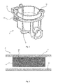
- the Fig. 2 shows a schematic perspective view of a nozzle holder 4 for a gas burner 3.
- the nozzle holder 4 preferably has a cup-shaped base body 5, in which a nozzle 9 (FIG. Fig. 1 ) of the gas burner 3 can be received.
- the main body 5 is made for example of an aluminum or magnesium material.
- the nozzle holder 4 also has a connecting portion 6, which is connected to the base body 5.
- the connecting portion 6 is positively and / or materially connected to the base body 5.
- the connecting portion 6 is connected to the base body 5 in such a way that it can not be removed from the base body 5 in a non-destructive way.
- the main body 5 may be cast or molded onto the connecting portion 6 in a metal die casting process or a metal injection molding process.
- the connecting portion 6 can be glued to the base body 5, welded, caulked, screwed and / or riveted.
- the connecting section 6 preferably has a steel material.
- the connecting portion 6 may be made of a steel sheet, for example.
- the connecting section 6 is in particular disc-shaped and preferably runs completely around the cup-shaped main body 5.
- the nozzle holder 4 can continue Attachment eyelets 11 have. However, the attachment eyelets 11 are not required for attaching the nozzle holder 4 to the cover plate 7.
- the Fig. 3 shows a schematic sectional view of a gas hob 2 according to the Fig. 1 ,
- the gas hob 2 or the hearth 1 has a cover plate 7 covering the nozzle holder 4 or a so-called top sheet or a trough top side. Furthermore, the gas hob 2 and the stove 1, a bottom tray 8.
- the nozzle holders 4 are positioned between the cover plate 7 and the bottom tray 8.
- the floor pan 8 may be made of a steel sheet.
- the cover plate 7 is arranged parallel to and spaced from the bottom tray 8.
- the nozzle holder 4 is connected by means of a compound 10 with the cover plate 7 such that the nozzle holder 4 is not removable or detachable from the cover plate 7.
- the term "non-removable” or “non-detachable” or “insoluble” in the present case means that the nozzle holder 4 and the cover plate 7 can be separated from each other only by destroying the connection 10, the cover plate 7 and / or the nozzle holder 4. When disconnecting the connection 10, this, the nozzle holder 4 and / or the cover plate 7 is destroyed.
- the nozzle holder 4 may be welded or glued to the cover plate 7.
- the nozzle holder 4 is at least partially made of a magnesium or aluminum material.
- the cover plate 7 is preferably made of a steel material.
- the cover plate 7 is made of a steel sheet.
- the nozzle holder 4 can be connected to the cover plate 7 with the aid of the connecting section 6 made of a steel material.
- the connecting portion 6 is welded to the cover plate 7, glued, caulked or the like. This makes it possible to dispense with screwing or riveting of the nozzle holder 4 with the cover plate 7.
Landscapes
- Engineering & Computer Science (AREA)
- Chemical & Material Sciences (AREA)
- Combustion & Propulsion (AREA)
- Mechanical Engineering (AREA)
- General Engineering & Computer Science (AREA)
- Gas Burners (AREA)
- Combinations Of Kitchen Furniture (AREA)
- Baking, Grill, Roasting (AREA)
Abstract
Description
- Die vorliegende Erfindung betrifft eine Gaskochstelle und einen Herd.
- Ein Gasherd weist zumeist eine Kochmulde auf. Jede Kochmulde umfasst ein sogenanntes Top Sheet, an dem Düsenhalter von Gasbrennern des Herds befestigt sein können. Üblicherweise werden die Düsenhalter wieder lösbar mit dem Top Sheet verschraubt.
- Vor diesem Hintergrund besteht eine Aufgabe der vorliegenden Erfindung darin, eine verbesserte Gaskochstelle zur Verfügung zu stellen.
- Demgemäß wird eine Gaskochstelle mit zumindest einem Düsenhalter zum Halten einer Düse eines Gasbrenners der Gaskochstelle und einer Deckplatte vorgeschlagen, wobei der Düsenhalter derart stoffschlüssig mit der Deckplatte verbunden ist, dass eine Verbindung des Düsenhalters und der Deckplatte nicht lösbar, insbesondere nicht zerstörungsfrei lösbar, ist.
- Hierdurch kann auf zusätzliche Befestigungselemente wie beispielsweise Schrauben verzichtet werden. Insbesondere ist der Düsenhalter unlösbar mit der Deckplatte verbunden. Unter "nicht zerstörungsfrei" oder "unlösbar" ist zu verstehen, dass der Düsenhalter und die Deckplatte so miteinander verbunden sind, dass beim Trennen des Düsenhalters von der Deckplatte die Verbindung zwischen dem Düsenhalter und der Deckplatte, der Düsenhalter und/oder die Deckplatte beschädigt werden.
- Gemäß einer Ausführungsform ist der Düsenhalter mit der Deckplatte verschweißt, verlötet oder verklebt.
- Die Verbindung zwischen dem Düsenhalter und der Deckplatte kann beispielsweise eine Schweiß- oder Lötnaht oder Verklebung sein. Insbesondere ist der Düsenhalter mit Hilfe einer hitzebeständigen Verklebung mit der Deckplatte verbunden. Der Düsenhalter kann zusätzlich auch formschlüssig mit der Deckplatte verbunden sein. Unter einer "stoffschlüssigen Verbindung" wird vorliegend auch eine Klebeverbindung verstanden. Der Düsenhalter kann beispielsweise auch mit der Deckplatte verstemmt sein.
- Gemäß einer weiteren Ausführungsform ist der Düsenhalter aus einem Aluminiumwerkstoff gefertigt und die Deckplatte ist aus einem Stahlwerkstoff gefertigt.
- Insbesondere ist der Düsenhalter zumindest teilweise aus dem Aluminiumwerkstoff gefertigt. Alternativ kann der Düsenhalter beispielsweise aus einem Magnesiumwerkstoff gefertigt sein oder zumindest Magnesium aufweisen. Die Deckplatte kann beispielsweise aus einem Stahlblech gefertigt sein.
- Gemäß einer weiteren Ausführungsform weist der Düsenhalter einen Verbindungsabschnitt auf, der mit der Deckplatte verbindbar, insbesondere verschweißbar, ist.
- Der Verbindungsabschnitt kann auch mit der Deckplatte verklebbar oder verstemmbar sein.
- Gemäß einer weiteren Ausführungsform weist der Verbindungsabschnitt einen Stahlwerkstoff auf.
- Beispielsweise ist der Verbindungsabschnitt aus einem Stahlblech gefertigt. Hierdurch kann der Verbindungsabschnitt mit der aus einem Stahlwerkstoff gefertigten Deckplatte verschweißt werden.
- Gemäß einer weiteren Ausführungsform ist der Verbindungsabschnitt formschlüssig und/oder stoffschlüssig mit einem Grundkörper des Düsenhalters verbunden.
- Hierdurch ist eine zuverlässige und langlebige Verbindung des Düsenhalters mit der Deckplatte gewährleistet.
- Gemäß einer weiteren Ausführungsform ist der Grundkörper in einem Metalldruckgussverfahren oder einem Metallspritzgussverfahren an den Verbindungsabschnitt angegossen oder angespritzt.
- Hierdurch ist eine kostengünstige Serienproduktion des Düsenhalters möglich. Weiterhin ergibt sich hierdurch eine zuverlässige und langlebige Verbindung des Verbindungsabschnitts mit dem Grundkörper.
- Gemäß einer weiteren Ausführungsform ist der Verbindungsabschnitt mit dem Grundkörper verklebt, verschweißt, verstemmt, verschraubt und/oder vernietet.
- Hierdurch ergibt sich ebenfalls eine zuverlässige und langlebige Verbindung des Verbindungsabschnitts mit dem Grundkörper.
- Gemäß einer weiteren Ausführungsform ist der Verbindungsabschnitt scheibenförmig.
- Gemäß einer weiteren Ausführungsform umläuft der Verbindungsabschnitt um den Grundkörper.
- Weiterhin wird ein Herd vorgeschlagen. Der Herd umfasst mindestens eine derartige Gaskochstelle.
- Der Herd ist vorzugsweise ein Haushaltsgerät. Die Gaskochstelle ist vorzugsweise Teil eines Haushaltsgeräts.
- Weitere mögliche Implementierungen der Gaskochstelle und des Herds umfassen auch nicht explizit genannte Kombinationen von zuvor oder im Folgenden bezüglich der Ausführungsbeispiele beschriebenen Merkmalen oder Ausführungsformen. Dabei wird der Fachmann auch Einzelaspekte als Verbesserungen oder Ergänzungen zu der jeweiligen Grundform der Erfindung hinzufügen.
- Weitere vorteilhafte Ausgestaltungen und Aspekte der Erfindung sind Gegenstand der Unteransprüche sowie der im Folgenden beschriebenen Ausführungsbeispiele der Erfindung. Im Weiteren wird die Erfindung anhand von bevorzugten Ausführungsformen unter Bezugnahme auf die beigelegten Figuren näher erläutert.
-
Fig. 1 zeigt eine schematische Aufsicht einer Ausführungsform eines Herds; -
Fig. 2 zeigt eine schematische perspektivische Ansicht einer Ausführungsform eines Düsenhalters eines Gasbrenners des Herds gemäß derFig. 1 ; und -
Fig. 3 zeigt eine schematische Schnittansicht des Herds gemäß derFig. 1 . - In den Figuren sind gleiche oder funktionsgleiche Elemente mit denselben Bezugszeichen versehen worden, sofern nichts anderes angegeben ist.
- Die
Fig. 1 zeigt eine schematische Aufsicht auf einen Herd 1. Der Herd 1 ist insbesondere ein Gasherd mit einer Kochmulde. Der Herd 1 weist zumindest eine, insbesondere jedoch mehrere, Gaskochstellen 2 auf. Jeder Gaskochstelle 2 kann ein Gasbrenner 3 zugeordnet sein. - Die
Fig. 2 zeigt eine schematische perspektivische Ansicht eines Düsenhalters 4 für einen Gasbrenner 3. Der Düsenhalter 4 weist vorzugsweise einen topfförmigen Grundkörper 5 auf, in dem eine Düse 9 (Fig. 1 ) des Gasbrenners 3 aufnehmbar ist. Der Grundkörper 5 ist z.B. aus einem Aluminium- oder Magnesiumwerkstoff gefertigt. - Der Düsenhalter 4 weist ferner einen Verbindungsabschnitt 6 auf, der mit dem Grundkörper 5 verbunden ist. Der Verbindungsabschnitt 6 ist formschlüssig und/oder stoffschlüssig mit dem Grundkörper 5 verbunden. Insbesondere ist der Verbindungsabschnitt 6 derart mit dem Grundkörper 5 verbunden, dass dieser nicht zerstörungsfrei von dem Grundkörper 5 entfernbar ist.
- Beispielsweise kann der Grundkörper 5 in einem Metalldruckgussverfahren oder einem Metallspritzgussverfahren an den Verbindungsabschnitt 6 angegossen oder angespritzt sein. Weiterhin kann der Verbindungsabschnitt 6 mit dem Grundkörper 5 verklebt, verschweißt, verstemmt, verschraubt und/oder vernietet sein.
- Der Verbindungsabschnitt 6 weist vorzugsweise einen Stahlwerkstoff auf. Der Verbindungsabschnitt 6 kann beispielsweise aus einem Stahlblech gefertigt sein. Der Verbindungsabschnitt 6 ist insbesondere scheibenförmig und läuft um den topfförmigen Grundkörper 5 vorzugsweise vollständig um. Der Düsenhalter 4 kann weiterhin Befestigungsösen 11 aufweisen. Die Befestigungsösen 11 sind jedoch zum Befestigen des Düsenhalters 4 an der Deckplatte 7 nicht erforderlich.
- Die
Fig. 3 zeigt eine schematische Schnittansicht einer Gaskochstelle 2 gemäß derFig. 1 . Die Gaskochstelle 2 bzw. der Herd 1 weist eine die Düsenhalter 4 abdeckende Deckplatte 7 oder ein sogenanntes Top Sheet oder eine Muldenoberseite auf. Weiterhin weist die Gaskochstelle 2 bzw. der Herd 1 eine Bodenwanne 8 auf. Die Düsenhalter 4 sind zwischen der Deckplatte 7 und der Bodenwanne 8 positioniert. Die Bodenwanne 8 kann aus einem Stahlblech gefertigt sein. Die Deckplatte 7 ist parallel zu und beabstandet von der Bodenwanne 8 angeordnet. - Der Düsenhalter 4 ist mi Hilfe einer Verbindung 10 derart mit der Deckplatte 7 verbunden, dass der Düsenhalter 4 von der Deckplatte 7 nicht entfernbar oder lösbar ist. Unter "nicht entfernbar" oder "nicht lösbar" bzw. "unlösbar" ist vorliegend zu verstehen, dass der Düsenhalter 4 und die Deckplatte 7 nur durch Zerstörung der Verbindung 10, der Deckplatte 7 und/oder des Düsenhalters 4 voneinander trennbar sind. Beim Trennen der Verbindung 10 wird diese, der Düsenhalter 4 und/oder die Deckplatte 7 zerstört. Beispielsweise kann der Düsenhalter 4 mit der Deckplatte 7 verschweißt oder verklebt sein.
- Wie zuvor beschrieben, ist der Düsenhalter 4 zumindest abschnittsweise aus einem Magnesium- oder Aluminiumwerkstoff gefertigt. Die Deckplatte 7 ist vorzugsweise aus einem Stahlwerkstoff gefertigt. Beispielsweise ist die Deckplatte 7 aus einem Stahlblech gefertigt. Der Düsenhalter 4 ist mit Hilfe des aus einem Stahlwerkstoff gefertigten Verbindungsabschnitts 6 mit der Deckplatte 7 verbindbar. Insbesondere ist der Verbindungsabschnitt 6 mit der Deckplatte 7 verschweißt, verklebt, verstemmt oder dergleichen. Hierdurch kann auf ein Verschrauben oder Vernieten des Düsenhalters 4 mit der Deckplatte 7 verzichtet werden.
- Obwohl die vorliegende Erfindung anhand von Ausführungsbeispielen beschrieben wurde, ist sie vielfältig modifizierbar.
-
- 1
- Herd
- 2
- Gaskochstelle
- 3
- Gasbrenner
- 4
- Düsenhalter
- 5
- Grundkörper
- 6
- Verbindungsabschnitt
- 7
- Deckplatte
- 8
- Bodenwanne
- 9
- Düse
- 10
- Verbindung
- 11
- Befestigungsöse
Claims (11)
- Gaskochstelle (2) mit zumindest einem Düsenhalter (4) zum Halten einer Düse (9) eines Gasbrenners (3) der Gaskochstelle (2) und einer Deckplatte (7), wobei der Düsenhalter (4) derart stoffschlüssig mit der Deckplatte (7) verbunden ist, dass eine Verbindung (10) des Düsenhalters (4) und der Deckplatte (7) nicht lösbar, insbesondere nicht zerstörungsfrei lösbar, ist.
- Gaskochstelle nach Anspruch 1, dadurch gekennzeichnet, dass der Düsenhalter (4) mit der Deckplatte (7) verschweißt, verlötet oder verklebt ist.
- Gaskochstelle nach Anspruch 1, dadurch gekennzeichnet, dass der Düsenhalter (4) aus einem Aluminiumwerkstoff und dass die Deckplatte (7) aus einem Stahlwerkstoff gefertigt ist.
- Gaskochstelle nach Anspruch 3, dadurch gekennzeichnet, dass der Düsenhalter (4) einen Verbindungsabschnitt (6) aufweist, der mit der Deckplatte (7) verbindbar, insbesondere verschweißbar, ist.
- Gaskochstelle nach Anspruch 4, dadurch gekennzeichnet, dass der Verbindungsabschnitt (6) einen Stahlwerkstoff aufweist.
- Gaskochstelle nach Anspruch 4 oder 5, dadurch gekennzeichnet, dass der Verbindungsabschnitt (6) formschlüssig und/oder stoffschlüssig mit einem Grundkörper (5) des Düsenhalters (4) verbunden ist.
- Gaskochstelle nach einem der Ansprüche 4 - 6, dadurch gekennzeichnet, dass der Grundkörper (5) in einem Metalldruckgussverfahren oder einem Metallspritzgussverfahren an den Verbindungsabschnitt (6) angegossen oder angespritzt ist.
- Gaskochstelle nach einem der Ansprüche 4 - 6, dadurch gekennzeichnet, dass der Verbindungsabschnitt (6) mit dem Grundkörper (5) verklebt, verschweißt, verstemmt, verschraubt und/oder vernietet ist.
- Gaskochstelle nach einem der Ansprüche 4 - 8, dadurch gekennzeichnet, dass der Verbindungsabschnitt (6) scheibenförmig ist.
- Gaskochstelle nach einem der Ansprüche 4 - 9, dadurch gekennzeichnet, dass der Verbindungsabschnitt (6) um den Grundkörper (5) umläuft.
- Herd (1) mit mindestens einer Gaskochstelle (2) nach einem der Ansprüche 1 - 10.
Applications Claiming Priority (1)
| Application Number | Priority Date | Filing Date | Title |
|---|---|---|---|
| ES201430800A ES2552583B1 (es) | 2014-05-28 | 2014-05-28 | Punto de cocción a gas y cocina |
Publications (2)
| Publication Number | Publication Date |
|---|---|
| EP2950001A1 true EP2950001A1 (de) | 2015-12-02 |
| EP2950001B1 EP2950001B1 (de) | 2018-03-28 |
Family
ID=53177243
Family Applications (1)
| Application Number | Title | Priority Date | Filing Date |
|---|---|---|---|
| EP15167843.0A Not-in-force EP2950001B1 (de) | 2014-05-28 | 2015-05-15 | Gaskochstelle und herd |
Country Status (2)
| Country | Link |
|---|---|
| EP (1) | EP2950001B1 (de) |
| ES (2) | ES2552583B1 (de) |
Citations (9)
| Publication number | Priority date | Publication date | Assignee | Title |
|---|---|---|---|---|
| GB975426A (en) * | 1960-06-20 | 1964-11-18 | Procedes Sauter | Gas burners |
| US3405703A (en) * | 1965-10-25 | 1968-10-15 | Bahco Ab | Portable stove |
| EP0216693A1 (de) * | 1985-09-13 | 1987-04-01 | Compagnie Europeenne Pour L'equipement Menager "Cepem" | Gaszufuhrvorrichtung für Kochbrenner |
| US5052920A (en) * | 1988-10-11 | 1991-10-01 | Lincoln Brass Works, Inc. | Gas burner and method |
| DE19853795A1 (de) * | 1998-11-21 | 2000-07-06 | Kueppersbusch Hausgeraete Ag | Gaskochgerät |
| WO2000040900A1 (en) * | 1998-12-30 | 2000-07-13 | Ardem Pi̇şi̇ri̇ci̇ Ve Isitici Ci̇hazlar Sanavi̇i̇ A.Ş. | Deep drawn burner mechanism |
| DE10041472C1 (de) * | 2000-08-24 | 2002-04-18 | Schott Glas | Gasstrahlungsbrenner |
| EP1251310A1 (de) * | 2001-04-18 | 2002-10-23 | Sourdillon | Gasgargerät |
| EP1406043A1 (de) * | 2002-10-04 | 2004-04-07 | Burner Systems International (BSI) | Gasbrenner |
Family Cites Families (2)
| Publication number | Priority date | Publication date | Assignee | Title |
|---|---|---|---|---|
| US5186158A (en) * | 1990-08-23 | 1993-02-16 | Lincoln Brass Works, Inc. | Gas burner |
| FR2823836B1 (fr) * | 2001-04-18 | 2005-07-22 | Sourdillon Sa | Appareil de cuisson a gaz |
-
2014
- 2014-05-28 ES ES201430800A patent/ES2552583B1/es not_active Revoked
-
2015
- 2015-05-15 EP EP15167843.0A patent/EP2950001B1/de not_active Not-in-force
- 2015-05-15 ES ES15167843.0T patent/ES2665171T3/es active Active
Patent Citations (9)
| Publication number | Priority date | Publication date | Assignee | Title |
|---|---|---|---|---|
| GB975426A (en) * | 1960-06-20 | 1964-11-18 | Procedes Sauter | Gas burners |
| US3405703A (en) * | 1965-10-25 | 1968-10-15 | Bahco Ab | Portable stove |
| EP0216693A1 (de) * | 1985-09-13 | 1987-04-01 | Compagnie Europeenne Pour L'equipement Menager "Cepem" | Gaszufuhrvorrichtung für Kochbrenner |
| US5052920A (en) * | 1988-10-11 | 1991-10-01 | Lincoln Brass Works, Inc. | Gas burner and method |
| DE19853795A1 (de) * | 1998-11-21 | 2000-07-06 | Kueppersbusch Hausgeraete Ag | Gaskochgerät |
| WO2000040900A1 (en) * | 1998-12-30 | 2000-07-13 | Ardem Pi̇şi̇ri̇ci̇ Ve Isitici Ci̇hazlar Sanavi̇i̇ A.Ş. | Deep drawn burner mechanism |
| DE10041472C1 (de) * | 2000-08-24 | 2002-04-18 | Schott Glas | Gasstrahlungsbrenner |
| EP1251310A1 (de) * | 2001-04-18 | 2002-10-23 | Sourdillon | Gasgargerät |
| EP1406043A1 (de) * | 2002-10-04 | 2004-04-07 | Burner Systems International (BSI) | Gasbrenner |
Also Published As
| Publication number | Publication date |
|---|---|
| ES2552583B1 (es) | 2016-09-14 |
| ES2552583A1 (es) | 2015-11-30 |
| ES2665171T3 (es) | 2018-04-24 |
| EP2950001B1 (de) | 2018-03-28 |
Similar Documents
| Publication | Publication Date | Title |
|---|---|---|
| EP0677264B1 (de) | Topfförmiges Gar- und/oder Kochgerät | |
| EP2989946B1 (de) | Grill | |
| EP1530941A1 (de) | Gefäss zum Kochen von Speisen mit einer Einrichtung zum Anzeigen der erreichten Temperatur | |
| EP3278025A1 (de) | Gasbrenner und gaskochfeld | |
| EP3679301B1 (de) | Topfträger, gaskochstelle und verfahren zum herstellen eines topfträgers | |
| EP2950001B1 (de) | Gaskochstelle und herd | |
| DE715630C (de) | Kochtopf aus Aluminium mit einem durch aufgepresste Auflagen verstaerkten Boden | |
| DE3713685C1 (de) | Verfahren zum Anbringen einer Kunststoffarmatur an einem Krug aus zerbrechlichem Material | |
| DE202016000820U1 (de) | Gaskochgerät für einen Wok und andere Garbehältnisse | |
| EP2476957B1 (de) | Gaskochfeld | |
| EP3018409B1 (de) | Gaskochstelle mit brennerunterteil für einen gasbrenner | |
| DE102012103478B4 (de) | Behälter einer landwirtschaftlichen Verteilmaschine | |
| DE3416571C2 (de) | ||
| WO2016071821A1 (de) | Gaskochmulde | |
| EP3161386B1 (de) | Gaskochstelle | |
| DE683228C (de) | Turmkochvorrichtung | |
| EP3012527A1 (de) | Gaskochstelle und kochfeld | |
| DE102016105617A1 (de) | Haltegegenstand | |
| EP2952817A1 (de) | Hausgeräte-bedienanordnung, gasventil und herd | |
| DE102008044235A1 (de) | Kochfeld mit einer Kochfeldplatte, welche mit einem Montagerahmen verbunden ist, sowie Verfahren zum Herstellen eines Kochfelds | |
| AT165113B (de) | Herdplatte, insbesondere für Gasherde und Verfahren zu ihrer Herstellung | |
| DE468317C (de) | Befestigung von plattenartigen Seitenteilen an Gaskochern, Gasherden, Tischen o. dgl. | |
| DE920957C (de) | Brennstoffbeschickungsvorrichtung | |
| DE2138256A1 (de) | Fixier- und montageplatte fuer die zuend- und/oder sicherungseinrichtungen an gasbrennern von herden | |
| EP2860455A1 (de) | Positioniereinrichtung zum Positionieren eines Gasbrenners in oder an einer Kochmulde, Kochmulde und Gasherd |
Legal Events
| Date | Code | Title | Description |
|---|---|---|---|
| AK | Designated contracting states |
Kind code of ref document: A1 Designated state(s): AL AT BE BG CH CY CZ DE DK EE ES FI FR GB GR HR HU IE IS IT LI LT LU LV MC MK MT NL NO PL PT RO RS SE SI SK SM TR |
|
| AX | Request for extension of the european patent |
Extension state: BA ME |
|
| PUAI | Public reference made under article 153(3) epc to a published international application that has entered the european phase |
Free format text: ORIGINAL CODE: 0009012 |
|
| 17P | Request for examination filed |
Effective date: 20160602 |
|
| RBV | Designated contracting states (corrected) |
Designated state(s): AL AT BE BG CH CY CZ DE DK EE ES FI FR GB GR HR HU IE IS IT LI LT LU LV MC MK MT NL NO PL PT RO RS SE SI SK SM TR |
|
| 17Q | First examination report despatched |
Effective date: 20161121 |
|
| GRAP | Despatch of communication of intention to grant a patent |
Free format text: ORIGINAL CODE: EPIDOSNIGR1 |
|
| INTG | Intention to grant announced |
Effective date: 20171017 |
|
| GRAS | Grant fee paid |
Free format text: ORIGINAL CODE: EPIDOSNIGR3 |
|
| GRAA | (expected) grant |
Free format text: ORIGINAL CODE: 0009210 |
|
| AK | Designated contracting states |
Kind code of ref document: B1 Designated state(s): AL AT BE BG CH CY CZ DE DK EE ES FI FR GB GR HR HU IE IS IT LI LT LU LV MC MK MT NL NO PL PT RO RS SE SI SK SM TR |
|
| REG | Reference to a national code |
Ref country code: GB Ref legal event code: FG4D Free format text: NOT ENGLISH |
|
| REG | Reference to a national code |
Ref country code: CH Ref legal event code: EP |
|
| REG | Reference to a national code |
Ref country code: AT Ref legal event code: REF Ref document number: 983788 Country of ref document: AT Kind code of ref document: T Effective date: 20180415 |
|
| REG | Reference to a national code |
Ref country code: IE Ref legal event code: FG4D Free format text: LANGUAGE OF EP DOCUMENT: GERMAN |
|
| REG | Reference to a national code |
Ref country code: DE Ref legal event code: R096 Ref document number: 502015003586 Country of ref document: DE |
|
| REG | Reference to a national code |
Ref country code: ES Ref legal event code: FG2A Ref document number: 2665171 Country of ref document: ES Kind code of ref document: T3 Effective date: 20180424 |
|
| REG | Reference to a national code |
Ref country code: FR Ref legal event code: PLFP Year of fee payment: 4 |
|
| PG25 | Lapsed in a contracting state [announced via postgrant information from national office to epo] |
Ref country code: FI Free format text: LAPSE BECAUSE OF FAILURE TO SUBMIT A TRANSLATION OF THE DESCRIPTION OR TO PAY THE FEE WITHIN THE PRESCRIBED TIME-LIMIT Effective date: 20180328 Ref country code: NO Free format text: LAPSE BECAUSE OF FAILURE TO SUBMIT A TRANSLATION OF THE DESCRIPTION OR TO PAY THE FEE WITHIN THE PRESCRIBED TIME-LIMIT Effective date: 20180628 Ref country code: LT Free format text: LAPSE BECAUSE OF FAILURE TO SUBMIT A TRANSLATION OF THE DESCRIPTION OR TO PAY THE FEE WITHIN THE PRESCRIBED TIME-LIMIT Effective date: 20180328 Ref country code: HR Free format text: LAPSE BECAUSE OF FAILURE TO SUBMIT A TRANSLATION OF THE DESCRIPTION OR TO PAY THE FEE WITHIN THE PRESCRIBED TIME-LIMIT Effective date: 20180328 |
|
| REG | Reference to a national code |
Ref country code: NL Ref legal event code: MP Effective date: 20180328 |
|
| REG | Reference to a national code |
Ref country code: LT Ref legal event code: MG4D |
|
| PG25 | Lapsed in a contracting state [announced via postgrant information from national office to epo] |
Ref country code: BG Free format text: LAPSE BECAUSE OF FAILURE TO SUBMIT A TRANSLATION OF THE DESCRIPTION OR TO PAY THE FEE WITHIN THE PRESCRIBED TIME-LIMIT Effective date: 20180628 Ref country code: GR Free format text: LAPSE BECAUSE OF FAILURE TO SUBMIT A TRANSLATION OF THE DESCRIPTION OR TO PAY THE FEE WITHIN THE PRESCRIBED TIME-LIMIT Effective date: 20180629 Ref country code: SE Free format text: LAPSE BECAUSE OF FAILURE TO SUBMIT A TRANSLATION OF THE DESCRIPTION OR TO PAY THE FEE WITHIN THE PRESCRIBED TIME-LIMIT Effective date: 20180328 Ref country code: LV Free format text: LAPSE BECAUSE OF FAILURE TO SUBMIT A TRANSLATION OF THE DESCRIPTION OR TO PAY THE FEE WITHIN THE PRESCRIBED TIME-LIMIT Effective date: 20180328 Ref country code: RS Free format text: LAPSE BECAUSE OF FAILURE TO SUBMIT A TRANSLATION OF THE DESCRIPTION OR TO PAY THE FEE WITHIN THE PRESCRIBED TIME-LIMIT Effective date: 20180328 |
|
| PG25 | Lapsed in a contracting state [announced via postgrant information from national office to epo] |
Ref country code: MT Free format text: LAPSE BECAUSE OF FAILURE TO SUBMIT A TRANSLATION OF THE DESCRIPTION OR TO PAY THE FEE WITHIN THE PRESCRIBED TIME-LIMIT Effective date: 20180328 |
|
| PG25 | Lapsed in a contracting state [announced via postgrant information from national office to epo] |
Ref country code: PL Free format text: LAPSE BECAUSE OF FAILURE TO SUBMIT A TRANSLATION OF THE DESCRIPTION OR TO PAY THE FEE WITHIN THE PRESCRIBED TIME-LIMIT Effective date: 20180328 Ref country code: EE Free format text: LAPSE BECAUSE OF FAILURE TO SUBMIT A TRANSLATION OF THE DESCRIPTION OR TO PAY THE FEE WITHIN THE PRESCRIBED TIME-LIMIT Effective date: 20180328 Ref country code: AL Free format text: LAPSE BECAUSE OF FAILURE TO SUBMIT A TRANSLATION OF THE DESCRIPTION OR TO PAY THE FEE WITHIN THE PRESCRIBED TIME-LIMIT Effective date: 20180328 Ref country code: NL Free format text: LAPSE BECAUSE OF FAILURE TO SUBMIT A TRANSLATION OF THE DESCRIPTION OR TO PAY THE FEE WITHIN THE PRESCRIBED TIME-LIMIT Effective date: 20180328 Ref country code: RO Free format text: LAPSE BECAUSE OF FAILURE TO SUBMIT A TRANSLATION OF THE DESCRIPTION OR TO PAY THE FEE WITHIN THE PRESCRIBED TIME-LIMIT Effective date: 20180328 |
|
| PG25 | Lapsed in a contracting state [announced via postgrant information from national office to epo] |
Ref country code: CZ Free format text: LAPSE BECAUSE OF FAILURE TO SUBMIT A TRANSLATION OF THE DESCRIPTION OR TO PAY THE FEE WITHIN THE PRESCRIBED TIME-LIMIT Effective date: 20180328 Ref country code: SM Free format text: LAPSE BECAUSE OF FAILURE TO SUBMIT A TRANSLATION OF THE DESCRIPTION OR TO PAY THE FEE WITHIN THE PRESCRIBED TIME-LIMIT Effective date: 20180328 Ref country code: SK Free format text: LAPSE BECAUSE OF FAILURE TO SUBMIT A TRANSLATION OF THE DESCRIPTION OR TO PAY THE FEE WITHIN THE PRESCRIBED TIME-LIMIT Effective date: 20180328 |
|
| REG | Reference to a national code |
Ref country code: CH Ref legal event code: PL |
|
| PG25 | Lapsed in a contracting state [announced via postgrant information from national office to epo] |
Ref country code: PT Free format text: LAPSE BECAUSE OF FAILURE TO SUBMIT A TRANSLATION OF THE DESCRIPTION OR TO PAY THE FEE WITHIN THE PRESCRIBED TIME-LIMIT Effective date: 20180730 |
|
| REG | Reference to a national code |
Ref country code: DE Ref legal event code: R097 Ref document number: 502015003586 Country of ref document: DE |
|
| REG | Reference to a national code |
Ref country code: BE Ref legal event code: MM Effective date: 20180531 |
|
| PG25 | Lapsed in a contracting state [announced via postgrant information from national office to epo] |
Ref country code: DK Free format text: LAPSE BECAUSE OF FAILURE TO SUBMIT A TRANSLATION OF THE DESCRIPTION OR TO PAY THE FEE WITHIN THE PRESCRIBED TIME-LIMIT Effective date: 20180328 Ref country code: MC Free format text: LAPSE BECAUSE OF FAILURE TO SUBMIT A TRANSLATION OF THE DESCRIPTION OR TO PAY THE FEE WITHIN THE PRESCRIBED TIME-LIMIT Effective date: 20180328 |
|
| PLBE | No opposition filed within time limit |
Free format text: ORIGINAL CODE: 0009261 |
|
| STAA | Information on the status of an ep patent application or granted ep patent |
Free format text: STATUS: NO OPPOSITION FILED WITHIN TIME LIMIT |
|
| REG | Reference to a national code |
Ref country code: IE Ref legal event code: MM4A |
|
| PG25 | Lapsed in a contracting state [announced via postgrant information from national office to epo] |
Ref country code: CH Free format text: LAPSE BECAUSE OF NON-PAYMENT OF DUE FEES Effective date: 20180531 Ref country code: LI Free format text: LAPSE BECAUSE OF NON-PAYMENT OF DUE FEES Effective date: 20180531 |
|
| 26N | No opposition filed |
Effective date: 20190103 |
|
| PG25 | Lapsed in a contracting state [announced via postgrant information from national office to epo] |
Ref country code: LU Free format text: LAPSE BECAUSE OF NON-PAYMENT OF DUE FEES Effective date: 20180515 |
|
| PG25 | Lapsed in a contracting state [announced via postgrant information from national office to epo] |
Ref country code: IE Free format text: LAPSE BECAUSE OF NON-PAYMENT OF DUE FEES Effective date: 20180515 |
|
| PG25 | Lapsed in a contracting state [announced via postgrant information from national office to epo] |
Ref country code: SI Free format text: LAPSE BECAUSE OF FAILURE TO SUBMIT A TRANSLATION OF THE DESCRIPTION OR TO PAY THE FEE WITHIN THE PRESCRIBED TIME-LIMIT Effective date: 20180328 Ref country code: BE Free format text: LAPSE BECAUSE OF NON-PAYMENT OF DUE FEES Effective date: 20180531 |
|
| PG25 | Lapsed in a contracting state [announced via postgrant information from national office to epo] |
Ref country code: TR Free format text: LAPSE BECAUSE OF FAILURE TO SUBMIT A TRANSLATION OF THE DESCRIPTION OR TO PAY THE FEE WITHIN THE PRESCRIBED TIME-LIMIT Effective date: 20180328 |
|
| PG25 | Lapsed in a contracting state [announced via postgrant information from national office to epo] |
Ref country code: MK Free format text: LAPSE BECAUSE OF NON-PAYMENT OF DUE FEES Effective date: 20180328 Ref country code: CY Free format text: LAPSE BECAUSE OF FAILURE TO SUBMIT A TRANSLATION OF THE DESCRIPTION OR TO PAY THE FEE WITHIN THE PRESCRIBED TIME-LIMIT Effective date: 20180328 Ref country code: HU Free format text: LAPSE BECAUSE OF FAILURE TO SUBMIT A TRANSLATION OF THE DESCRIPTION OR TO PAY THE FEE WITHIN THE PRESCRIBED TIME-LIMIT; INVALID AB INITIO Effective date: 20150515 |
|
| PG25 | Lapsed in a contracting state [announced via postgrant information from national office to epo] |
Ref country code: IS Free format text: LAPSE BECAUSE OF FAILURE TO SUBMIT A TRANSLATION OF THE DESCRIPTION OR TO PAY THE FEE WITHIN THE PRESCRIBED TIME-LIMIT Effective date: 20180728 |
|
| REG | Reference to a national code |
Ref country code: AT Ref legal event code: MM01 Ref document number: 983788 Country of ref document: AT Kind code of ref document: T Effective date: 20200515 |
|
| PGFP | Annual fee paid to national office [announced via postgrant information from national office to epo] |
Ref country code: FR Payment date: 20210525 Year of fee payment: 7 Ref country code: DE Payment date: 20210531 Year of fee payment: 7 Ref country code: IT Payment date: 20210531 Year of fee payment: 7 |
|
| PG25 | Lapsed in a contracting state [announced via postgrant information from national office to epo] |
Ref country code: AT Free format text: LAPSE BECAUSE OF NON-PAYMENT OF DUE FEES Effective date: 20200515 |
|
| PGFP | Annual fee paid to national office [announced via postgrant information from national office to epo] |
Ref country code: GB Payment date: 20210526 Year of fee payment: 7 Ref country code: ES Payment date: 20210618 Year of fee payment: 7 |
|
| REG | Reference to a national code |
Ref country code: DE Ref legal event code: R119 Ref document number: 502015003586 Country of ref document: DE |
|
| GBPC | Gb: european patent ceased through non-payment of renewal fee |
Effective date: 20220515 |
|
| PG25 | Lapsed in a contracting state [announced via postgrant information from national office to epo] |
Ref country code: FR Free format text: LAPSE BECAUSE OF NON-PAYMENT OF DUE FEES Effective date: 20220531 |
|
| PG25 | Lapsed in a contracting state [announced via postgrant information from national office to epo] |
Ref country code: GB Free format text: LAPSE BECAUSE OF NON-PAYMENT OF DUE FEES Effective date: 20220515 Ref country code: DE Free format text: LAPSE BECAUSE OF NON-PAYMENT OF DUE FEES Effective date: 20221201 |
|
| REG | Reference to a national code |
Ref country code: ES Ref legal event code: FD2A Effective date: 20230627 |
|
| PG25 | Lapsed in a contracting state [announced via postgrant information from national office to epo] |
Ref country code: IT Free format text: LAPSE BECAUSE OF NON-PAYMENT OF DUE FEES Effective date: 20220515 Ref country code: ES Free format text: LAPSE BECAUSE OF NON-PAYMENT OF DUE FEES Effective date: 20220516 |