EP2948733B1 - Procédé et dispositif destinés à déterminer la géométrie d'un véhicule - Google Patents
Procédé et dispositif destinés à déterminer la géométrie d'un véhicule Download PDFInfo
- Publication number
- EP2948733B1 EP2948733B1 EP13807960.3A EP13807960A EP2948733B1 EP 2948733 B1 EP2948733 B1 EP 2948733B1 EP 13807960 A EP13807960 A EP 13807960A EP 2948733 B1 EP2948733 B1 EP 2948733B1
- Authority
- EP
- European Patent Office
- Prior art keywords
- vehicle
- measurement
- mathematical model
- tyres
- tyre
- Prior art date
- Legal status (The legal status is an assumption and is not a legal conclusion. Google has not performed a legal analysis and makes no representation as to the accuracy of the status listed.)
- Not-in-force
Links
- 238000005259 measurement Methods 0.000 title claims description 25
- 238000000034 method Methods 0.000 title claims description 17
- 238000013178 mathematical model Methods 0.000 claims description 17
- 238000011156 evaluation Methods 0.000 claims description 7
- 238000001454 recorded image Methods 0.000 claims description 4
- 230000000903 blocking effect Effects 0.000 claims description 2
- 230000005484 gravity Effects 0.000 description 2
- 238000013459 approach Methods 0.000 description 1
- 230000006835 compression Effects 0.000 description 1
- 238000007906 compression Methods 0.000 description 1
- 230000003287 optical effect Effects 0.000 description 1
- 238000012545 processing Methods 0.000 description 1
- 238000005096 rolling process Methods 0.000 description 1
Images
Classifications
-
- G—PHYSICS
- G01—MEASURING; TESTING
- G01M—TESTING STATIC OR DYNAMIC BALANCE OF MACHINES OR STRUCTURES; TESTING OF STRUCTURES OR APPARATUS, NOT OTHERWISE PROVIDED FOR
- G01M17/00—Testing of vehicles
- G01M17/007—Wheeled or endless-tracked vehicles
-
- G—PHYSICS
- G01—MEASURING; TESTING
- G01B—MEASURING LENGTH, THICKNESS OR SIMILAR LINEAR DIMENSIONS; MEASURING ANGLES; MEASURING AREAS; MEASURING IRREGULARITIES OF SURFACES OR CONTOURS
- G01B11/00—Measuring arrangements characterised by the use of optical techniques
- G01B11/16—Measuring arrangements characterised by the use of optical techniques for measuring the deformation in a solid, e.g. optical strain gauge
- G01B11/168—Measuring arrangements characterised by the use of optical techniques for measuring the deformation in a solid, e.g. optical strain gauge by means of polarisation
-
- G—PHYSICS
- G06—COMPUTING; CALCULATING OR COUNTING
- G06T—IMAGE DATA PROCESSING OR GENERATION, IN GENERAL
- G06T7/00—Image analysis
- G06T7/0002—Inspection of images, e.g. flaw detection
- G06T7/0004—Industrial image inspection
- G06T7/001—Industrial image inspection using an image reference approach
-
- G—PHYSICS
- G06—COMPUTING; CALCULATING OR COUNTING
- G06T—IMAGE DATA PROCESSING OR GENERATION, IN GENERAL
- G06T7/00—Image analysis
- G06T7/70—Determining position or orientation of objects or cameras
- G06T7/73—Determining position or orientation of objects or cameras using feature-based methods
- G06T7/75—Determining position or orientation of objects or cameras using feature-based methods involving models
-
- G—PHYSICS
- G01—MEASURING; TESTING
- G01B—MEASURING LENGTH, THICKNESS OR SIMILAR LINEAR DIMENSIONS; MEASURING ANGLES; MEASURING AREAS; MEASURING IRREGULARITIES OF SURFACES OR CONTOURS
- G01B2210/00—Aspects not specifically covered by any group under G01B, e.g. of wheel alignment, caliper-like sensors
- G01B2210/10—Wheel alignment
- G01B2210/28—Beam projector and related sensors, camera, inclinometer or other active sensing or projecting device
- G01B2210/283—Beam projectors and related sensors
- G01B2210/286—Projecting a light pattern on the wheel or vehicle body
-
- G—PHYSICS
- G06—COMPUTING; CALCULATING OR COUNTING
- G06T—IMAGE DATA PROCESSING OR GENERATION, IN GENERAL
- G06T2207/00—Indexing scheme for image analysis or image enhancement
- G06T2207/10—Image acquisition modality
- G06T2207/10004—Still image; Photographic image
- G06T2207/10012—Stereo images
-
- G—PHYSICS
- G06—COMPUTING; CALCULATING OR COUNTING
- G06T—IMAGE DATA PROCESSING OR GENERATION, IN GENERAL
- G06T2207/00—Indexing scheme for image analysis or image enhancement
- G06T2207/30—Subject of image; Context of image processing
- G06T2207/30108—Industrial image inspection
-
- G—PHYSICS
- G06—COMPUTING; CALCULATING OR COUNTING
- G06T—IMAGE DATA PROCESSING OR GENERATION, IN GENERAL
- G06T2207/00—Indexing scheme for image analysis or image enhancement
- G06T2207/30—Subject of image; Context of image processing
- G06T2207/30248—Vehicle exterior or interior
- G06T2207/30252—Vehicle exterior; Vicinity of vehicle
Definitions
- the invention relates to a method and a device for checking the correct positioning of a vehicle on a measuring station for vehicle measurement.
- the flatness of the measuring station and an exactly horizontal orientation of the vehicle play a major role in achieving precise results during the survey.
- the manufacturers state that the maximum height difference between the wheel contact surfaces must not exceed 1 mm.
- a method for checking the correct positioning of a vehicle on a measuring station for vehicle measurement comprises the steps of recording images of at least two tires of the vehicle; identifying features in the captured images describing at least a portion of the respective captured tire; approximating a mathematical model to the identified features of the tire; determining the extent of flattening of each tire from the approximated mathematical model; and comparing the flattening of the at least two tires.
- the identified features describe in particular that region of the tire in which a flattening occurs, in particular a region arranged around the footprint of the tire.
- An inventive device for checking the correct positioning of a vehicle on a measuring station for vehicle measurement, in particular for checking a correct horizontal orientation of the vehicle, with at least two transducers, which are each adapted to receive images of a tire of the vehicle, has an evaluation device which is formed To identify features in the captured images describing at least a portion of the respective captured tire; to approximate a mathematical model to the identified features; determine the degree of flattening of each tire from the approximated mathematical model; and compare the flattening of at least two tires.
- a device according to the invention according to claim 7 and a method according to claim 1 according to the invention the proper horizontal alignment of the motor vehicle to be measured can be checked easily and conveniently and in particular automatically.
- a check according to the invention can be set up by updating the software of an existing measuring device without having to install additional hardware.
- the check according to the invention can therefore be implemented inexpensively both in new and in existing measuring stations.
- the evaluation device can be integrated into one of the transducers used for vehicle measurement.
- the device may have four or more transducers to capture all wheels of the vehicle at the same time.
- the method may additionally include the step of issuing a warning and / or blocking a planned vehicle measurement when the difference in the flattening of the tires exceeds a predetermined limit.
- Each tire or at least a portion of the tire can each be illuminated by a projector, which can be configured as a light or laser projector, in order to enable a structured image recording of the tire or of a partial area.
- a projector which can be configured as a light or laser projector, in order to enable a structured image recording of the tire or of a partial area.
- the pictures of the tires can be taken with a stereo camera as stereo images, in order to account for three-dimensional information.
- the mathematical model that is adapted to the recorded images may in particular be a two- or three-dimensional mathematical model, for example a rotationally symmetric polynomial model or a spline model.
- Such models have proven to be particularly well suited to produce a sufficiently accurate mathematical model of the tire with reasonable computational effort.
- the method may additionally include taking multiple images of each wheel as the vehicle passes by; to determine from the mathematical model rotation centers of wheels; and to check if the wheels have moved in one plane while passing by.
- the sensor is equipped with a gravity sensor that allows the sensor to be aligned in the gravity field of the sensor
- the orientation of the plane of the measuring station in the gravitational field of the earth can also be determined.
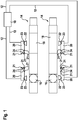
- FIG. 1 shows a schematic plan view of a measuring station for vehicle measurement.
- the measuring station has two mutually parallel rails 14, which may be, for example, the rails 14 of a lift.
- the rails 14 can also be installed firmly on the ground of the measuring station. Alternatively, the method can also be carried out without rails 14 on the floor of the measuring station.
- each of the two running rails 14 is equipped with a turning plate 16 which makes it possible to deflect the steerable wheels of a vehicle arranged on the running rails 14 when the vehicle is arranged on the running rails 14 such that its steerable wheels rest on the turning plates 16 are supported.
- the rails 14 each have a sliding plate 18.
- the sliding plates 18 are displaceable parallel to the longitudinal extent of the rails 14 and can thus be arranged at a variable distance from the associated rotary plate 16. In this way, the measuring station can be adapted to different vehicles having different distances between the front wheels and the rear wheels.
- transducers 20 are arranged in a rectangular arrangement.
- Two (front) transducers 20 are arranged at the height of the rotary plates 16 and thus adjacent to the usually steerable front wheels of a parked on the rails 14 vehicle.
- Two (rear) transducers 20 can be moved along the rails 14, so that their position can be adjusted to the center distance of the vehicle to be measured such that the rear transducers 20 are always positioned opposite the rear wheels of the vehicle parked on the rails 14.
- Each of the transducers 20 includes an image pickup device (image sensor) 22 for detecting a measured value, which is e.g. is designed as a (stereo) camera, and an integrated lighting device 23, which is designed to illuminate the wheel to be measured opposite the respective sensor 20.
- image sensor image sensor 22 for detecting a measured value
- integrated lighting device 23 which is designed to illuminate the wheel to be measured opposite the respective sensor 20.
- Each of the transducers 20 can also have position lights 21 and in each case one optical sensor 24 in order to be able to determine the position of the respective transducers 20 with respect to at least two other transducers 20.
- the transducers 20 are connected via data lines 12 to a central evaluation device 10. Alternatively, the transducers 20 can be wirelessly connected to the central evaluation device 10.
- the evaluation device 10 may also be arranged in one or more of the transducers 20.
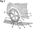
- FIG. 2 shows an example of a 3D point cloud, as recorded by a transducer 20, which is arranged on the left front wheel 8 of a vehicle.
- the affiliation of the recorded points to the wheel 8, to the body 2, for example the wheel arch 4, and to the roadway 14, 16 is determined. From the points associated with the tire 7 of the wheel 8, those points 7a belonging to the lower portion of the tire 7 flattened due to the self-weight of the vehicle are identified.
- a mathematical model in particular a so-called spline model, is adapted to the points which represent the tire 7 and in particular to the points 7 a of the lower, flattened region of the tire 7. From the parameters of the mathematical model, the flattening of the tire 7 can then be determined.
- This process is performed for at least two tires 7 of the vehicle, and the flattenings of the tires 7 are compared with each other. If the differences in the extent of the flattening between different tires 7 of a vehicle exceed a predefined limit value, a warning signal is output and / or a planned vehicle measurement is prevented since the vehicle measurement could no longer be performed with the required accuracy when the limit value is exceeded, but leads to incorrect results would lead.
- one or more images are taken of each wheel 8 as the vehicle travels onto or over the measuring station. From the at least one recorded image, in addition, the center of rotation Z of each wheel 8 can be determined.
- a suitable method is for example in DE 10 2006 048 725 A1 described.
- the invention thus makes it possible to conveniently and reliably check the conditions for a successful vehicle measurement, in particular a horizontal alignment of the vehicle body.
Landscapes
- Physics & Mathematics (AREA)
- General Physics & Mathematics (AREA)
- Engineering & Computer Science (AREA)
- Computer Vision & Pattern Recognition (AREA)
- Theoretical Computer Science (AREA)
- Quality & Reliability (AREA)
- Length Measuring Devices By Optical Means (AREA)
Claims (10)
- Procédé de contrôle de positionnement correct d'un véhicule sur un lieu de mesure pour le mesurage de véhicule, caractérisé en ce que le procédé comprend les étapes consistant :a) à capturer des images d'au moins deux pneus (7) du véhicule;b) à identifier dans les images capturées des caractéristiques qui décrivent au moins une zone du pneu (7) capturé respectif;c) à approcher un modèle mathématique des caractéristiques identifiées;d) à déterminer la dimension de l'aplatissement de chaque pneu (7) à partir du modèle mathématique approché;e) à comparer la dimension de l'aplatissement des aux moins deux pneus (7).
- Procédé selon la revendication 1, dont une étape supplémentaire consiste à émettre un avertissement et/ou à bloquer un mesurage de véhicule planifié si la différence d'aplatissement entre les pneus (7) dépasse une valeur limite prédéfinie.
- Procédé selon la revendication 1 ou 2, les pneus (7) étant respectivement éclairés par un projecteur (23).
- Procédé selon l'une quelconque des revendications précédentes, des images stéréoscopiques des pneus (7) étant capturées avec une caméra stéréoscopique (22).
- Procédé selon l'une quelconque des revendications précédentes, le modèle mathématique étant un modèle mathématique bidimensionnel ou tridimensionnel.
- Procédé selon l'une quelconque des revendications précédentes, le procédé consistant- à capturer au moins une image de chaque pneu (8) du véhicule pendant un passage du véhicule;- à déterminer les centres de rotation (Z) des roues (8) à partir du modèle mathématique; et- à contrôler si les centres de rotation (Z) des roues (8) se sont déplacés dans un plan pendant le passage.
- Dispositif de contrôle de positionnement correct d'un véhicule sur un lieu de mesure pour le mesurage de véhicule, pourvu d'au moins deux capteurs (20) de mesure qui servent respectivement à capturer des images d'un pneu (7) du véhicule, caractérisé en ce que le dispositif comporte un dispositif d'évaluation (10) qui sert- à identifier dans les images capturées des caractéristiques qui décrivent au moins une zone du pneu (7) capturé respectif;- à approcher un modèle mathématique des caractéristiques identifiées;- à déterminer la dimension de l'aplatissement de chaque pneu (7) à partir du modèle mathématique approché; et- à comparer la dimension de l'aplatissement d'au moins deux pneus (7) l'un par rapport à l'autre.
- Dispositif selon la revendication 6, le dispositif d'évaluation (10) étant intégré à au moins un des capteurs (20) de mesure.
- Dispositif selon la revendication 7 ou 8, le dispositif comportant quatre capteurs (20) de mesure.
- Dispositif de mesurage de véhicule qui comporte un dispositif de contrôle du positionnement correct d'un véhicule selon l'une quelconque des revendications 7 à 9.
Applications Claiming Priority (2)
| Application Number | Priority Date | Filing Date | Title |
|---|---|---|---|
| DE102013200910.0A DE102013200910A1 (de) | 2013-01-22 | 2013-01-22 | Verfahren und Vorrichtung zur Fahrzeugvermessung |
| PCT/EP2013/075897 WO2014114402A1 (fr) | 2013-01-22 | 2013-12-09 | Procédé et dispositif destinés à déterminer la géométrie d'un véhicule |
Publications (2)
| Publication Number | Publication Date |
|---|---|
| EP2948733A1 EP2948733A1 (fr) | 2015-12-02 |
| EP2948733B1 true EP2948733B1 (fr) | 2018-10-31 |
Family
ID=49779869
Family Applications (1)
| Application Number | Title | Priority Date | Filing Date |
|---|---|---|---|
| EP13807960.3A Not-in-force EP2948733B1 (fr) | 2013-01-22 | 2013-12-09 | Procédé et dispositif destinés à déterminer la géométrie d'un véhicule |
Country Status (5)
| Country | Link |
|---|---|
| US (1) | US9599538B2 (fr) |
| EP (1) | EP2948733B1 (fr) |
| CN (1) | CN104937366A (fr) |
| DE (1) | DE102013200910A1 (fr) |
| WO (1) | WO2014114402A1 (fr) |
Families Citing this family (7)
| Publication number | Priority date | Publication date | Assignee | Title |
|---|---|---|---|---|
| DE102014204809A1 (de) * | 2014-03-14 | 2015-09-17 | Robert Bosch Gmbh | Verfahren und Vorrichtung zum Überprüfen der Radaufhängung eines Fahrzeugs |
| CN105388028B (zh) * | 2015-11-24 | 2018-09-28 | 上海斐讯数据通信技术有限公司 | 移动终端及其检测汽车轮胎下沉量的方法和装置 |
| BR102017002219B1 (pt) * | 2017-02-02 | 2020-01-07 | Vale S/A | Sistema e método para o monitoramento de rodas ferroviárias |
| WO2018158995A1 (fr) * | 2017-02-28 | 2018-09-07 | パナソニックIpマネジメント株式会社 | Appareil de mesure de charge par essieu et procédé de mesure de charge par essieu |
| US10671873B2 (en) * | 2017-03-10 | 2020-06-02 | Tusimple, Inc. | System and method for vehicle wheel detection |
| CN111213192B (zh) * | 2017-10-31 | 2022-05-10 | 松下知识产权经营株式会社 | 双轮胎判定装置以及双轮胎判定方法 |
| CN116878402B (zh) * | 2023-07-11 | 2024-07-19 | 北京博科测试系统股份有限公司 | 非接触轮眉测量传感器及方法 |
Family Cites Families (11)
| Publication number | Priority date | Publication date | Assignee | Title |
|---|---|---|---|---|
| FR2602048A1 (fr) * | 1985-12-30 | 1988-01-29 | Clerc Alain | Dispositif pour evaluer la deformation des pneumatiques de vehicules |
| US5962779A (en) * | 1997-01-29 | 1999-10-05 | Shell Oil Company | Method for determining tire inflation status |
| US6237234B1 (en) * | 1999-09-28 | 2001-05-29 | Snap-On Technologies, Inc. | Method and apparatus for measuring vehicle wheel roll radius |
| US7336350B2 (en) * | 2002-05-15 | 2008-02-26 | Hunter Engineering Company | Wheel alignment apparatus and method utilizing three-dimensional imaging |
| US7702126B2 (en) * | 2004-12-15 | 2010-04-20 | Hunter Engineering Company | Vehicle lift measurement system |
| DE102005017624A1 (de) * | 2005-04-15 | 2006-10-19 | Robert Bosch Gmbh | Verfahren zum Bestimmen der Rad- und/oder Achsgeometrie von Kraftfahrzeugen |
| DE102006035924A1 (de) * | 2006-07-31 | 2008-02-07 | Robert Bosch Gmbh | Verfahren zum Bestimmen der Drehachse und des Drehzentrums eines Fahrzeugrads |
| DE102006048725A1 (de) * | 2006-10-16 | 2008-04-17 | Robert Bosch Gmbh | Verfahren zum Ermitteln der Drehachse eines Fahrzeugrades |
| US8650766B2 (en) * | 2008-09-12 | 2014-02-18 | Robert Bosch Gmbh | Target system, set of target systems and device for optically aligning an axle |
| JP5387202B2 (ja) * | 2009-07-23 | 2014-01-15 | 横浜ゴム株式会社 | タイヤ解析システムおよびタイヤ解析方法 |
| BR112014010638A2 (pt) * | 2011-11-03 | 2017-05-09 | Neomatix Ltd | sistema para estimar o estado da pressão pneumática de pneus para veículos |
-
2013
- 2013-01-22 DE DE102013200910.0A patent/DE102013200910A1/de not_active Withdrawn
- 2013-12-09 EP EP13807960.3A patent/EP2948733B1/fr not_active Not-in-force
- 2013-12-09 CN CN201380071040.9A patent/CN104937366A/zh active Pending
- 2013-12-09 US US14/762,625 patent/US9599538B2/en active Active
- 2013-12-09 WO PCT/EP2013/075897 patent/WO2014114402A1/fr active Application Filing
Non-Patent Citations (1)
| Title |
|---|
| None * |
Also Published As
| Publication number | Publication date |
|---|---|
| EP2948733A1 (fr) | 2015-12-02 |
| US9599538B2 (en) | 2017-03-21 |
| WO2014114402A1 (fr) | 2014-07-31 |
| CN104937366A (zh) | 2015-09-23 |
| DE102013200910A1 (de) | 2014-07-24 |
| US20150369701A1 (en) | 2015-12-24 |
Similar Documents
| Publication | Publication Date | Title |
|---|---|---|
| EP2948733B1 (fr) | Procédé et dispositif destinés à déterminer la géométrie d'un véhicule | |
| EP2539117B1 (fr) | Procédé et dispositif pour déterminer des distances sur un véhicule | |
| EP1042643B1 (fr) | Dispositif de determination de la geometrie de roues et/ou d'essieux de vehicules a moteur | |
| DE102012215754A1 (de) | Verfahren und Vorrichtung zur Fahrzeugvermessung | |
| EP1042644B1 (fr) | Dispositif de determination de la geometrie de roues et/ou d'essieux de vehicules a moteur | |
| EP2079982B1 (fr) | Procédé pour déterminer l'axe de rotation d'une roue d'un véhicule | |
| WO2014114403A1 (fr) | Dispositif et procédé pour la surveillance et le calibrage d'un dispositif de mesure de la profondeur des sculptures d'un pneu | |
| DE102008045307A1 (de) | Vorrichtung und Verfahren zum Bestimmen und Einstellen der Fahrwerksgeometrie eines Fahrzeuges | |
| DE102012202271A1 (de) | Vorrichtung und Verfahren zur Reifenprüfung | |
| DE102012224260A1 (de) | Vorrichtung und Verfahren zur Messung der Profiltiefe eines Reifens | |
| EP3612794B1 (fr) | Procédé et dispositif de contrôle de la géométrie des trains roulants | |
| DE102011087177A1 (de) | Verfahren zur Positionierung eines Messsystems und Messsystem zur Durchführung des Verfahrens | |
| WO2020038675A1 (fr) | Dispositif de mesure, dispositif, système, véhicule et procédé | |
| DE102013222291A1 (de) | Verfahren und Vorrichtung zur Schätzung der Einbauwinkel eines in einem Fahrzeug montierten bildgebenden Sensors | |
| EP2960883B1 (fr) | Détermination d'au moins une caractéristique d'un véhicule | |
| EP2839239B1 (fr) | Procédé de détermination de l'orientation d'au moins un rail de roulement d'un poste de mesure et dispositif permettant la mise en oeuvre dudit procédé | |
| WO2015197668A1 (fr) | Procédé et dispositif permettant de vérifier le poids de chargement d'un camion | |
| DE102019003238B4 (de) | Fahrzeugortung durch Kartenabgleich unter Berücksichtigung eines Straßenprofils | |
| DE69733766T2 (de) | Verfahren und vorrichtung zur ausrichtung von fahrzeugrädern | |
| EP4328540A1 (fr) | Dispositif et procédé de mesure de la profondeur de sculpture de pneus de véhicule | |
| DE102013021475A1 (de) | Optische Lenkwinkelbestimmung | |
| DE102006048726A1 (de) | Verfahren zum Vermessen der Rad- oder Achsgeometrie eines Fahrzeugs | |
| EP3611653A1 (fr) | Dispositif et procédé de détection d'un pneumatique d'un véhicule | |
| DE102005063050A1 (de) | Verfahren und Vorrichtung zur berührungslosen Messung der Achsgeometrie | |
| EP3688409B1 (fr) | Procédé de détermination d'un carrossage ou d'un pincement de roue |
Legal Events
| Date | Code | Title | Description |
|---|---|---|---|
| PUAI | Public reference made under article 153(3) epc to a published international application that has entered the european phase |
Free format text: ORIGINAL CODE: 0009012 |
|
| 17P | Request for examination filed |
Effective date: 20150824 |
|
| AK | Designated contracting states |
Kind code of ref document: A1 Designated state(s): AL AT BE BG CH CY CZ DE DK EE ES FI FR GB GR HR HU IE IS IT LI LT LU LV MC MK MT NL NO PL PT RO RS SE SI SK SM TR |
|
| AX | Request for extension of the european patent |
Extension state: BA ME |
|
| DAX | Request for extension of the european patent (deleted) | ||
| GRAP | Despatch of communication of intention to grant a patent |
Free format text: ORIGINAL CODE: EPIDOSNIGR1 |
|
| INTG | Intention to grant announced |
Effective date: 20180517 |
|
| GRAS | Grant fee paid |
Free format text: ORIGINAL CODE: EPIDOSNIGR3 |
|
| GRAA | (expected) grant |
Free format text: ORIGINAL CODE: 0009210 |
|
| AK | Designated contracting states |
Kind code of ref document: B1 Designated state(s): AL AT BE BG CH CY CZ DE DK EE ES FI FR GB GR HR HU IE IS IT LI LT LU LV MC MK MT NL NO PL PT RO RS SE SI SK SM TR |
|
| REG | Reference to a national code |
Ref country code: CH Ref legal event code: EP Ref country code: GB Ref legal event code: FG4D Free format text: NOT ENGLISH |
|
| REG | Reference to a national code |
Ref country code: AT Ref legal event code: REF Ref document number: 1059917 Country of ref document: AT Kind code of ref document: T Effective date: 20181115 |
|
| REG | Reference to a national code |
Ref country code: DE Ref legal event code: R096 Ref document number: 502013011509 Country of ref document: DE |
|
| REG | Reference to a national code |
Ref country code: IE Ref legal event code: FG4D Free format text: LANGUAGE OF EP DOCUMENT: GERMAN |
|
| REG | Reference to a national code |
Ref country code: NL Ref legal event code: MP Effective date: 20181031 |
|
| REG | Reference to a national code |
Ref country code: LT Ref legal event code: MG4D |
|
| PG25 | Lapsed in a contracting state [announced via postgrant information from national office to epo] |
Ref country code: NO Free format text: LAPSE BECAUSE OF FAILURE TO SUBMIT A TRANSLATION OF THE DESCRIPTION OR TO PAY THE FEE WITHIN THE PRESCRIBED TIME-LIMIT Effective date: 20190131 Ref country code: BG Free format text: LAPSE BECAUSE OF FAILURE TO SUBMIT A TRANSLATION OF THE DESCRIPTION OR TO PAY THE FEE WITHIN THE PRESCRIBED TIME-LIMIT Effective date: 20190131 Ref country code: LT Free format text: LAPSE BECAUSE OF FAILURE TO SUBMIT A TRANSLATION OF THE DESCRIPTION OR TO PAY THE FEE WITHIN THE PRESCRIBED TIME-LIMIT Effective date: 20181031 Ref country code: FI Free format text: LAPSE BECAUSE OF FAILURE TO SUBMIT A TRANSLATION OF THE DESCRIPTION OR TO PAY THE FEE WITHIN THE PRESCRIBED TIME-LIMIT Effective date: 20181031 Ref country code: LV Free format text: LAPSE BECAUSE OF FAILURE TO SUBMIT A TRANSLATION OF THE DESCRIPTION OR TO PAY THE FEE WITHIN THE PRESCRIBED TIME-LIMIT Effective date: 20181031 Ref country code: PL Free format text: LAPSE BECAUSE OF FAILURE TO SUBMIT A TRANSLATION OF THE DESCRIPTION OR TO PAY THE FEE WITHIN THE PRESCRIBED TIME-LIMIT Effective date: 20181031 Ref country code: HR Free format text: LAPSE BECAUSE OF FAILURE TO SUBMIT A TRANSLATION OF THE DESCRIPTION OR TO PAY THE FEE WITHIN THE PRESCRIBED TIME-LIMIT Effective date: 20181031 Ref country code: ES Free format text: LAPSE BECAUSE OF FAILURE TO SUBMIT A TRANSLATION OF THE DESCRIPTION OR TO PAY THE FEE WITHIN THE PRESCRIBED TIME-LIMIT Effective date: 20181031 Ref country code: IS Free format text: LAPSE BECAUSE OF FAILURE TO SUBMIT A TRANSLATION OF THE DESCRIPTION OR TO PAY THE FEE WITHIN THE PRESCRIBED TIME-LIMIT Effective date: 20190228 |
|
| REG | Reference to a national code |
Ref country code: DE Ref legal event code: R082 Ref document number: 502013011509 Country of ref document: DE Representative=s name: SCHMITT-NILSON SCHRAUD WAIBEL WOHLFROM PATENTA, DE Ref country code: DE Ref legal event code: R081 Ref document number: 502013011509 Country of ref document: DE Owner name: BEISSBARTH GMBH, DE Free format text: FORMER OWNER: ROBERT BOSCH GMBH, 70469 STUTTGART, DE |
|
| PG25 | Lapsed in a contracting state [announced via postgrant information from national office to epo] |
Ref country code: PT Free format text: LAPSE BECAUSE OF FAILURE TO SUBMIT A TRANSLATION OF THE DESCRIPTION OR TO PAY THE FEE WITHIN THE PRESCRIBED TIME-LIMIT Effective date: 20190301 Ref country code: GR Free format text: LAPSE BECAUSE OF FAILURE TO SUBMIT A TRANSLATION OF THE DESCRIPTION OR TO PAY THE FEE WITHIN THE PRESCRIBED TIME-LIMIT Effective date: 20190201 Ref country code: NL Free format text: LAPSE BECAUSE OF FAILURE TO SUBMIT A TRANSLATION OF THE DESCRIPTION OR TO PAY THE FEE WITHIN THE PRESCRIBED TIME-LIMIT Effective date: 20181031 Ref country code: SE Free format text: LAPSE BECAUSE OF FAILURE TO SUBMIT A TRANSLATION OF THE DESCRIPTION OR TO PAY THE FEE WITHIN THE PRESCRIBED TIME-LIMIT Effective date: 20181031 Ref country code: RS Free format text: LAPSE BECAUSE OF FAILURE TO SUBMIT A TRANSLATION OF THE DESCRIPTION OR TO PAY THE FEE WITHIN THE PRESCRIBED TIME-LIMIT Effective date: 20181031 Ref country code: AL Free format text: LAPSE BECAUSE OF FAILURE TO SUBMIT A TRANSLATION OF THE DESCRIPTION OR TO PAY THE FEE WITHIN THE PRESCRIBED TIME-LIMIT Effective date: 20181031 |
|
| REG | Reference to a national code |
Ref country code: GB Ref legal event code: 732E Free format text: REGISTERED BETWEEN 20190523 AND 20190529 |
|
| RAP2 | Party data changed (patent owner data changed or rights of a patent transferred) |
Owner name: BEISSBARTH GMBH |
|
| PG25 | Lapsed in a contracting state [announced via postgrant information from national office to epo] |
Ref country code: CZ Free format text: LAPSE BECAUSE OF FAILURE TO SUBMIT A TRANSLATION OF THE DESCRIPTION OR TO PAY THE FEE WITHIN THE PRESCRIBED TIME-LIMIT Effective date: 20181031 Ref country code: DK Free format text: LAPSE BECAUSE OF FAILURE TO SUBMIT A TRANSLATION OF THE DESCRIPTION OR TO PAY THE FEE WITHIN THE PRESCRIBED TIME-LIMIT Effective date: 20181031 |
|
| REG | Reference to a national code |
Ref country code: CH Ref legal event code: PL |
|
| REG | Reference to a national code |
Ref country code: DE Ref legal event code: R097 Ref document number: 502013011509 Country of ref document: DE |
|
| PG25 | Lapsed in a contracting state [announced via postgrant information from national office to epo] |
Ref country code: MC Free format text: LAPSE BECAUSE OF FAILURE TO SUBMIT A TRANSLATION OF THE DESCRIPTION OR TO PAY THE FEE WITHIN THE PRESCRIBED TIME-LIMIT Effective date: 20181031 Ref country code: SK Free format text: LAPSE BECAUSE OF FAILURE TO SUBMIT A TRANSLATION OF THE DESCRIPTION OR TO PAY THE FEE WITHIN THE PRESCRIBED TIME-LIMIT Effective date: 20181031 Ref country code: RO Free format text: LAPSE BECAUSE OF FAILURE TO SUBMIT A TRANSLATION OF THE DESCRIPTION OR TO PAY THE FEE WITHIN THE PRESCRIBED TIME-LIMIT Effective date: 20181031 Ref country code: LU Free format text: LAPSE BECAUSE OF NON-PAYMENT OF DUE FEES Effective date: 20181209 Ref country code: EE Free format text: LAPSE BECAUSE OF FAILURE TO SUBMIT A TRANSLATION OF THE DESCRIPTION OR TO PAY THE FEE WITHIN THE PRESCRIBED TIME-LIMIT Effective date: 20181031 Ref country code: SM Free format text: LAPSE BECAUSE OF FAILURE TO SUBMIT A TRANSLATION OF THE DESCRIPTION OR TO PAY THE FEE WITHIN THE PRESCRIBED TIME-LIMIT Effective date: 20181031 |
|
| PLBE | No opposition filed within time limit |
Free format text: ORIGINAL CODE: 0009261 |
|
| STAA | Information on the status of an ep patent application or granted ep patent |
Free format text: STATUS: NO OPPOSITION FILED WITHIN TIME LIMIT |
|
| REG | Reference to a national code |
Ref country code: IE Ref legal event code: MM4A |
|
| REG | Reference to a national code |
Ref country code: BE Ref legal event code: MM Effective date: 20181231 |
|
| 26N | No opposition filed |
Effective date: 20190801 |
|
| PG25 | Lapsed in a contracting state [announced via postgrant information from national office to epo] |
Ref country code: SI Free format text: LAPSE BECAUSE OF FAILURE TO SUBMIT A TRANSLATION OF THE DESCRIPTION OR TO PAY THE FEE WITHIN THE PRESCRIBED TIME-LIMIT Effective date: 20181031 Ref country code: IE Free format text: LAPSE BECAUSE OF NON-PAYMENT OF DUE FEES Effective date: 20181209 |
|
| PG25 | Lapsed in a contracting state [announced via postgrant information from national office to epo] |
Ref country code: BE Free format text: LAPSE BECAUSE OF NON-PAYMENT OF DUE FEES Effective date: 20181231 |
|
| PG25 | Lapsed in a contracting state [announced via postgrant information from national office to epo] |
Ref country code: LI Free format text: LAPSE BECAUSE OF NON-PAYMENT OF DUE FEES Effective date: 20181231 Ref country code: CH Free format text: LAPSE BECAUSE OF NON-PAYMENT OF DUE FEES Effective date: 20181231 |
|
| PG25 | Lapsed in a contracting state [announced via postgrant information from national office to epo] |
Ref country code: MT Free format text: LAPSE BECAUSE OF FAILURE TO SUBMIT A TRANSLATION OF THE DESCRIPTION OR TO PAY THE FEE WITHIN THE PRESCRIBED TIME-LIMIT Effective date: 20181031 |
|
| REG | Reference to a national code |
Ref country code: AT Ref legal event code: MM01 Ref document number: 1059917 Country of ref document: AT Kind code of ref document: T Effective date: 20181209 |
|
| PG25 | Lapsed in a contracting state [announced via postgrant information from national office to epo] |
Ref country code: TR Free format text: LAPSE BECAUSE OF FAILURE TO SUBMIT A TRANSLATION OF THE DESCRIPTION OR TO PAY THE FEE WITHIN THE PRESCRIBED TIME-LIMIT Effective date: 20181031 |
|
| PG25 | Lapsed in a contracting state [announced via postgrant information from national office to epo] |
Ref country code: AT Free format text: LAPSE BECAUSE OF NON-PAYMENT OF DUE FEES Effective date: 20181209 |
|
| PG25 | Lapsed in a contracting state [announced via postgrant information from national office to epo] |
Ref country code: CY Free format text: LAPSE BECAUSE OF FAILURE TO SUBMIT A TRANSLATION OF THE DESCRIPTION OR TO PAY THE FEE WITHIN THE PRESCRIBED TIME-LIMIT Effective date: 20181031 Ref country code: MK Free format text: LAPSE BECAUSE OF NON-PAYMENT OF DUE FEES Effective date: 20181031 Ref country code: HU Free format text: LAPSE BECAUSE OF FAILURE TO SUBMIT A TRANSLATION OF THE DESCRIPTION OR TO PAY THE FEE WITHIN THE PRESCRIBED TIME-LIMIT; INVALID AB INITIO Effective date: 20131209 |
|
| PGFP | Annual fee paid to national office [announced via postgrant information from national office to epo] |
Ref country code: FR Payment date: 20211220 Year of fee payment: 9 Ref country code: GB Payment date: 20211222 Year of fee payment: 9 |
|
| PGFP | Annual fee paid to national office [announced via postgrant information from national office to epo] |
Ref country code: DE Payment date: 20220228 Year of fee payment: 9 |
|
| PGFP | Annual fee paid to national office [announced via postgrant information from national office to epo] |
Ref country code: IT Payment date: 20211230 Year of fee payment: 9 |
|
| REG | Reference to a national code |
Ref country code: DE Ref legal event code: R119 Ref document number: 502013011509 Country of ref document: DE |
|
| GBPC | Gb: european patent ceased through non-payment of renewal fee |
Effective date: 20221209 |
|
| PG25 | Lapsed in a contracting state [announced via postgrant information from national office to epo] |
Ref country code: GB Free format text: LAPSE BECAUSE OF NON-PAYMENT OF DUE FEES Effective date: 20221209 Ref country code: DE Free format text: LAPSE BECAUSE OF NON-PAYMENT OF DUE FEES Effective date: 20230701 |
|
| PG25 | Lapsed in a contracting state [announced via postgrant information from national office to epo] |
Ref country code: FR Free format text: LAPSE BECAUSE OF NON-PAYMENT OF DUE FEES Effective date: 20221231 |
|
| PG25 | Lapsed in a contracting state [announced via postgrant information from national office to epo] |
Ref country code: IT Free format text: LAPSE BECAUSE OF NON-PAYMENT OF DUE FEES Effective date: 20221209 |