EP2948021B1 - Pinzettenartiges gehäuse zum auftragen eines kosmetikproduktes - Google Patents
Pinzettenartiges gehäuse zum auftragen eines kosmetikproduktes Download PDFInfo
- Publication number
- EP2948021B1 EP2948021B1 EP13872784.7A EP13872784A EP2948021B1 EP 2948021 B1 EP2948021 B1 EP 2948021B1 EP 13872784 A EP13872784 A EP 13872784A EP 2948021 B1 EP2948021 B1 EP 2948021B1
- Authority
- EP
- European Patent Office
- Prior art keywords
- wiper
- container
- neck
- applicator
- overcap
- Prior art date
- Legal status (The legal status is an assumption and is not a legal conclusion. Google has not performed a legal analysis and makes no representation as to the accuracy of the status listed.)
- Active
Links
- 239000002537 cosmetic Substances 0.000 title description 12
- 210000003128 head Anatomy 0.000 claims description 79
- 210000000720 eyelash Anatomy 0.000 claims description 12
- 210000004209 hair Anatomy 0.000 claims description 9
- 210000001520 comb Anatomy 0.000 claims description 6
- 210000000080 chela (arthropods) Anatomy 0.000 description 18
- -1 polyethylene Polymers 0.000 description 6
- 230000000694 effects Effects 0.000 description 4
- 239000000463 material Substances 0.000 description 4
- 238000000034 method Methods 0.000 description 4
- 239000000203 mixture Substances 0.000 description 4
- 239000004743 Polypropylene Substances 0.000 description 3
- 230000000295 complement effect Effects 0.000 description 3
- 239000013536 elastomeric material Substances 0.000 description 3
- 229920001155 polypropylene Polymers 0.000 description 3
- 238000007789 sealing Methods 0.000 description 3
- 229920002943 EPDM rubber Polymers 0.000 description 2
- 239000004698 Polyethylene Substances 0.000 description 2
- 239000000853 adhesive Substances 0.000 description 2
- 230000001070 adhesive effect Effects 0.000 description 2
- FACXGONDLDSNOE-UHFFFAOYSA-N buta-1,3-diene;styrene Chemical compound C=CC=C.C=CC1=CC=CC=C1.C=CC1=CC=CC=C1 FACXGONDLDSNOE-UHFFFAOYSA-N 0.000 description 2
- 230000001010 compromised effect Effects 0.000 description 2
- 230000000994 depressogenic effect Effects 0.000 description 2
- 239000005038 ethylene vinyl acetate Substances 0.000 description 2
- 238000001746 injection moulding Methods 0.000 description 2
- 230000033001 locomotion Effects 0.000 description 2
- 238000000465 moulding Methods 0.000 description 2
- 229920001200 poly(ethylene-vinyl acetate) Polymers 0.000 description 2
- 229920000728 polyester Polymers 0.000 description 2
- 229920000573 polyethylene Polymers 0.000 description 2
- 230000000717 retained effect Effects 0.000 description 2
- 238000000926 separation method Methods 0.000 description 2
- 229920000468 styrene butadiene styrene block copolymer Polymers 0.000 description 2
- 238000003466 welding Methods 0.000 description 2
- VSKJLJHPAFKHBX-UHFFFAOYSA-N 2-methylbuta-1,3-diene;styrene Chemical compound CC(=C)C=C.C=CC1=CC=CC=C1.C=CC1=CC=CC=C1 VSKJLJHPAFKHBX-UHFFFAOYSA-N 0.000 description 1
- 229920000459 Nitrile rubber Polymers 0.000 description 1
- 239000004952 Polyamide Substances 0.000 description 1
- 229920002614 Polyether block amide Polymers 0.000 description 1
- 230000002411 adverse Effects 0.000 description 1
- 230000005540 biological transmission Effects 0.000 description 1
- 229920001400 block copolymer Polymers 0.000 description 1
- 239000011248 coating agent Substances 0.000 description 1
- 238000000576 coating method Methods 0.000 description 1
- 238000010276 construction Methods 0.000 description 1
- 238000001816 cooling Methods 0.000 description 1
- 230000009977 dual effect Effects 0.000 description 1
- 229920001971 elastomer Polymers 0.000 description 1
- 239000000806 elastomer Substances 0.000 description 1
- 210000004709 eyebrow Anatomy 0.000 description 1
- 210000000744 eyelid Anatomy 0.000 description 1
- 229920001903 high density polyethylene Polymers 0.000 description 1
- 239000004700 high-density polyethylene Substances 0.000 description 1
- 238000007654 immersion Methods 0.000 description 1
- 230000001788 irregular Effects 0.000 description 1
- 229920000126 latex Polymers 0.000 description 1
- 239000004816 latex Substances 0.000 description 1
- 229920001684 low density polyethylene Polymers 0.000 description 1
- 239000004702 low-density polyethylene Substances 0.000 description 1
- 239000012768 molten material Substances 0.000 description 1
- 229920001778 nylon Polymers 0.000 description 1
- 238000004806 packaging method and process Methods 0.000 description 1
- 229920003023 plastic Polymers 0.000 description 1
- 239000004033 plastic Substances 0.000 description 1
- 229920002647 polyamide Polymers 0.000 description 1
- 239000004417 polycarbonate Substances 0.000 description 1
- 229920000515 polycarbonate Polymers 0.000 description 1
- 229920001296 polysiloxane Polymers 0.000 description 1
- 229920002635 polyurethane Polymers 0.000 description 1
- 239000004814 polyurethane Substances 0.000 description 1
- 239000004800 polyvinyl chloride Substances 0.000 description 1
- 229920000915 polyvinyl chloride Polymers 0.000 description 1
- 230000000284 resting effect Effects 0.000 description 1
- 239000007787 solid Substances 0.000 description 1
- 239000012815 thermoplastic material Substances 0.000 description 1
- 239000002699 waste material Substances 0.000 description 1
- 230000004580 weight loss Effects 0.000 description 1
Images


Classifications
-
- A—HUMAN NECESSITIES
- A45—HAND OR TRAVELLING ARTICLES
- A45D—HAIRDRESSING OR SHAVING EQUIPMENT; EQUIPMENT FOR COSMETICS OR COSMETIC TREATMENTS, e.g. FOR MANICURING OR PEDICURING
- A45D40/00—Casings or accessories specially adapted for storing or handling solid or pasty toiletry or cosmetic substances, e.g. shaving soaps or lipsticks
- A45D40/26—Appliances specially adapted for applying pasty paint, e.g. using roller, using a ball
- A45D40/262—Appliances specially adapted for applying pasty paint, e.g. using roller, using a ball using a brush or the like
- A45D40/265—Appliances specially adapted for applying pasty paint, e.g. using roller, using a ball using a brush or the like connected to the cap of the container
- A45D40/267—Appliances specially adapted for applying pasty paint, e.g. using roller, using a ball using a brush or the like connected to the cap of the container comprising a wiper
-
- A—HUMAN NECESSITIES
- A45—HAND OR TRAVELLING ARTICLES
- A45D—HAIRDRESSING OR SHAVING EQUIPMENT; EQUIPMENT FOR COSMETICS OR COSMETIC TREATMENTS, e.g. FOR MANICURING OR PEDICURING
- A45D40/00—Casings or accessories specially adapted for storing or handling solid or pasty toiletry or cosmetic substances, e.g. shaving soaps or lipsticks
- A45D40/26—Appliances specially adapted for applying pasty paint, e.g. using roller, using a ball
Definitions
- the invention is in the field of cosmetic product applicator systems. More specifically, it relates to tweezer type applicators in combination with a product container and customized wiper system, especially for applying mascara.
- a typical mascara applicator comprises a threaded handle, a stem and an applicator head.
- a common container of mascara has a threaded neck that leads into a cylindrical reservoir of product.
- a wiper is located in the neck, and has a lower orifice that is designed to wipe the stem and applicator head as they pass through the wiper.
- the handle is screwed onto the neck of the container, the stem rotates around the central longitudinal axis of the wiper.
- the wiper orifice is able to tightly hug the perimeter of the stem for efficient wiping. If the stem was not coaxial with wiper, then the wiper orifice would have to be large enough to accommodate the orbit of the stem. In that case, the orifice would not hug the perimeter of the stem, and the wiping function would be compromised.
- a tweezers is a pair of levers that have proximal ends that articulate with each other (either directly or through an intermediate member) and distal ends that remain free.
- the articulation acts as a fulcrum, and is such that an internal tension is stored in the articulation that tends to push the levers toward a rest position.
- the rest position corresponds to no applied pressure.
- the rest position means that the distal ends of the levers are spaced apart, and application of external pressure brings them closer together to effect a pincer grip.
- the articulation may be effected by welding or unitary construction or any type of joint that can hold and release tension as just described.
- US5,611,361 discloses a mascara applicator-container system in which the applicator comprises a handle, one end of a stem rigidly connected to and extending from the handle, and two applicator heads extending from the other end of the stem.
- the applicator heads and stem may be immersed in a container of product, and the handle may be threaded onto the neck of the container.
- the handle As the handle is threaded onto the neck, the applicator heads revolve around the axis of the container neck. There are no wipers in the neck or container, nor anything else to interfere with the revolution of the applicator heads.
- the system suffers from not having wipers to remove excess product and clumps from the applicator heads, a feature that is often considered essential for good results.
- the multiple applicator heads are not really intended to be used in a tweezer fashion.
- US6,325,071 discloses a tweezer type applicator system for mascara.
- the system has a dual bladed mascara applicator which is received in a cylindrical product container.
- a wiper has a disc shape with two apertures to accept the applicator blades.
- a wiper housing receives the wiper and is rotatable in the product container.
- pressure is applied near the middle of the blades.
- the level of product in the container and the placement of the wiper in the container is relatively low, well below the orifice of the container. According to the patent, only about one third of the container can be filled with product, which is well below conventional mascara fill levels.
- the container must be fashioned with a custom lip on its inner wall, to give the wiper housing something against which to rest, to prevent unwanted vertical movement of the wiper.
- the low product fill level is a great waste of container space compared to conventional mascara applicator systems.
- WO 2004/077987 A1 discloses another structure of a mascara applicator with movable arms.
- a main object of the invention is to provide an improved tweezer type cosmetic applicator system, especially for mascara.
- Another object of the invention is to provide a tweezer cosmetic applicator system that utilizes a standard container that may be filled to conventional levels.
- Another object of the invention is to provide a tweezer cosmetic applicator system that effects a pincer grip without the application of external pressure.
- Another object of the invention is to provide a tweezer cosmetic applicator system that enables better evacuation of the product container.
- Another object is to provide a mascara applicator system that achieves acceptable evacuation of a non-cylindrical container.
- the present invention is a tweezer type applicator system as defined in appended claims, said system comprising a product container, a rotating wiper system, a fulcrum, two applicator heads that are biased to form a pincer grip, and an overcap that has means to release the pincer grip.
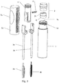
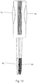
- FIGs 1 , 2a and 2b depict one embodiment of an applicator according to the present invention
- figure 3 is an exploded view thereof.
- This applicator system comprises a product container (1), a wiper system (2), two articulating stems (3a, 3b), two applicator heads (4a, 4b), a fulcrum (5), a spring (6), and an overcap (7) that has means to pressure the articulating stems.
- Figure 1 depicts the applicator in a nearly closed or rest position.
- Figure 2b depicts the applicator in an opened position.
- a preferred embodiment of a container (1) comprises an inside wall or internal surface (1f) that defines a reservoir (1 a) for holding a cosmetic or personal care product (P) that is to be applied by the applicator.
- the container further comprises a neck (1 b) having an orifice (1 c) which together form a passageway from the exterior of the container into the reservoir.
- the neck comprises screw threads (1 d) that cooperate with an overcap (7).
- the neck is able to receive into itself a wiper system, and retain the wiper system against unintentional removal.
- the neck of the container may have a notch (1e) which can be used to secure the wiper housing (2a) against unwanted rotation (see figure 5 ).
- it is possible to make the container non-cylindrical, and still achieve acceptable evacuation of product.
- a wiper that can clean and prepare two applicator heads for use is secured in the neck (1 b) of the container (1) such that the wiper is free to rotate, but not come out of the neck.
- a wiper system (2) comprises a wiper housing (2a) and a wiper (2b).
- the wiper housing is roughly cylindrical and hollow.
- a lower portion (2c) of the wiper housing is designed to be secured in the neck (1 b) of the container (1). This is preferably achieved with a friction fit that makes an effective seal, as commonly done in the art, but other means, such as adhesive, overmolding, or integral molding, may be used.
- the friction fit and seal between the wiper housing and neck may be enhanced with a sealing ring (2d), as shown on the lower portion of the wiper.
- the lower portion also comprises an internal ring (2e), which cooperates with the wiper (2b).
- An upper portion (2f) of the wiper housing extends above the neck of the container.
- Preferred embodiments of the wiper housing have a beveled surface (2q) near the top of the wiper housing, which cooperates with the overcap (7).
- a flange (2g) rests against the top of the neck. The flange prevents the housing from being inserted too far into the container, and improves the seal between the neck and wiper housing.
- the flange also cooperates with the overcap.
- the wiper housing is fashioned of an elastomeric material.
- the wiper housing may have a detent (2o, see figure 5 ) which registers with the notch (1 e) of the neck (1 b) of the container, to secure the wiper housing against unwanted rotation.
- the wiper depends from the wiper housing (2a) and extends down into the neck of the container.
- An upper portion (2h) of the wiper is cylindrical and designed to fit into, and be retained in the lower portion (2c) of the wiper housing.
- the wiper has a circumferential channel (2i) for receiving internal ring (2e) of the wiper housing (2a). This fitment is sufficiently snug that the wiper does not back out of the housing during intended use, but the wiper is able to rotate relative to the housing.
- a lower portion (2j) of the wiper is tapered, and there are two passageways (2k, 2l) through the wiper, for servicing applicator heads (4a, 4b) and stems (3a, 3b).
- the lower orifices (2m, 2n) of the wiper are sized to scrape the stems and applicator heads, as they pass through the wiper.
- the lower orifices Preferably, the lower orifices have the same shape as the cross section of stems (3a, 3b) In some preferred embodiments, the shapes and diameters of the two orifices are the same.
- the wiper is fashioned of an elastomeric material.
- a tweezer type package comprises two articulating stems (3a, 3b).
- Each stem has a distal end (3c, 3d) and a proximal end (3e, 3f).
- the distal ends support applicator heads (4a, 4b).
- the distal ends of the stems with the applicator heads attached are able to pass through the wiper housing, each stem/applicator head entering into one of the passageways (2k, 2l), and emerging into the reservoir (1 a) of the container (1).
- the length of the stems is such that in the fully assembled system, the applicator heads are able to scrape the internal surface of the bottom (1g) of the container.
- tweezers A simple type of tweezers was described above. That type is often seen in cosmetic packaging, such as that described in US6,325,071 .
- Preferred embodiments of the present invention use a different type of tweezers, in which "rest position" means that the distal ends of the levers are touching in a pincer grip, while application of external pressure to the levers moves them apart and breaks the grip.
- rest position means that the distal ends of the levers are touching in a pincer grip, while application of external pressure to the levers moves them apart and breaks the grip.
- tension is stored in the articulation that tends to push the levers toward their resting, or grip, position.
- the stems (3a, 3b), in between their proximal (3e, 3f) and distal (3c, 3d) ends (but nearer to their proximal ends) are formed to receive an axle in a pivoting arrangement.
- stem (3a) is formed as two circular collars (3g).
- stem (3b) is formed as one circular collar (3h).
- collar (3h) of stem (3b) fits in between collars (3g) of stem (3a). This arrangement allows the applicator heads (4a, 4b) to line up so that they come into contact in rest position.
- the collars may be partially open, as shown, and sufficiently flexible so that they may be snapped onto an axle (5c). Once on the axle, the two stems are articulated about the axle, and the distal ends (3c, 3d) of the stems move in an arc, sometimes closer together, sometimes further apart.
- each stem may have a groove (3i, 3j), for receiving opposite ends of a spring (6).
- Each groove is even closer to the proximal end than the collar, i.e. each stem articulates with the axle between its proximal and distal ends.
- the spring pushes apart the proximal ends of the stems, which brings together the applicator heads (4a, 4b) located at the distal ends of the stems. Under the internal pressure of the spring, the two applicator heads come together in a pincer grip.
- the pincer grip is sufficiently strong to perform the intended cosmetic application, but not so strong as to create any unpleasantness or damage to the user.
- the applicator heads are closed on the lashes near the base of the lashes.
- the pincer grip should be string enough to maintain firm contact with the lashes, but not so strong that it creates an unpleasant tugging of the lashes nor pulls out any eyelashes.
- an applicator for applying dye to hairs of the head may use a stronger pincer grip than a mascara applicator.
- external pressure must be supplied by a user to release the pincer grip and/or separate the applicator heads. Therefore, it is preferable if the pincer grip is not so strong that a user has difficulty separating the applicator heads.
- the characteristics of the spring (6) may be altered through trial and error to achieve an acceptable pincer grip for the given application.
- Applicator heads (4a, 4b) are attached to the distal ends of the stems (3a, 3b).
- an applicator head may form a snap fit with the distal end of a stem, or they may be joined by adhesive or welding or integrally molding.
- both applicator heads are loaded with the same product. So the intention of the invention is that both applicator heads be used to apply the same product, generally to the same body feature, i.e. the eyelashes or eyebrows or hair of the head or lips or nails, etc.
- the applicator heads may be identical.
- both applicator heads may be identical bristle brushes for applying mascara (as shown in figure 11 ), or identical combs for applying dye to the hair of the head.
- the applicator heads may be different.
- one applicator head may be a bristle brush, and the other may be a comb for eyelashes (as shown in figures 6 or 9 ).
- brushes and combs are distinguished, as commonly understood. Compared to combs, brushes have bristles that are generally more flexible, more numerous, and extending in many directions. Compared to brushes, combs have tines that are generally more stiff, less numerous, and presented in a single row with all tines basically parallel. Combs with more than one row of tines are also known in the art, but the tines are still much sparser than bristles in a brush.
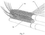
- figures 6 and 7 show a brush applicator head (4c) with numerous bristles pointing in all directions, and a comb (4d) with two rows of parallel tines. This particular embodiment is a preferred one for hair applications. It is especially effective for applying mascara to the eyelashes.
- any type of applicator head that lends itself to being immersed in product and passed through a wiper may be useful in the present invention.
- brushes include twisted wire core types, molded types and crimped types. Sponges may also be useful.
- the applicator heads (4a, 4b) are chosen to work together to apply a cosmetic composition. It is possible to use the two applicator heads sequentially, first one and then the other. However, preferred methods of application take advantage of the pincer grip that the applicator system is able to provide.
- the applicator system is used to apply product to hair (H), which lends itself to being gripped between the applicator heads (4a, 4b), and drawn through applicator heads which apply a constant pressure, to evenly spread the product (see figure 7 ).
- the fulcrum (5) comprises an upper portion (5a) and two downwardly depending legs (5b).
- An axle (5c) formed as a cylinder, extends from one leg to the other, and is fixedly attached thereto. As described above, the axle supports the collars (3g, 3h) of the stems (3a, 3b).
- the space (5d) between the legs is provided so that the proximal ends (3e, 3f) of the stems can approach each other, which increases the range of motion of the applicator heads.
- a housing (5e) for the spring (6) is also depending from the upper portion (5a) of the fulcrum (5).
- the housing is formed as a bored out member.
- the spring When assembled, the spring is disposed in the bore (5f), with either end of the spring extending beyond the member, so that the spring may contact the grooves (3i, 3j) of the proximal ends (3e, 3f) of the stems (3a, 3b).
- the characteristics of the spring should be chosen to achieve an acceptable pincer grip for the intended application.
- the force that the spring exerts on the stems depends on the material of the spring, its length, wire diameter, helix diameter and pitch. All of these may be varied to adjust the pincer grip, the length of the spring, however, should be as follows.
- the spring is long enough to always be in contact with both grooves. More preferably, the spring is longer than the greatest separation between the proximal ends of the stems. When this is the case, the two applicator heads (4a, 4b) will be forced together with some residual pressure to create a pincer grip.
- the fulcrum (5) is designed to fit into the overcap (7) and be retained in the overcap.
- the shape of the fulcrum may be complementary to the shape of the inside of the overcap. For example, both may be approximately cylindrical.
- the fulcrum may be provided with one or more raised snaps (5h) which cooperate with one or more detents (7e) on an inner surface of the overcap, to hold the fulcrum inside the overcap (see figure 9 ).
- the fulcrum may be provided with features that ensure that the fulcrum and overcap are rigidly joined so that they move as one.
- the fulcrum may have ribs (5g) which grip complementary grooves (7f) on an inner surface of the overcap. In this way, when the overcap is rotated, the fulcrum is also rotated, there being no appreciable slippage between the two.
- the overcap (7) is a housing for the fulcrum (5), as just described.
- the inner surface of the overcap (7) may be provided with one or more detents (7e) which cooperate with one or more raised snaps (5h) of the fulcrum (5), to hold the fulcrum inside the overcap (see figure 8 ).
- the overcap may be provided with features that ensure that the overcap and fulcrum move as one.
- the inner surface of the overcap may have grooves (7f) which grip complementary ribs (5g) of the fulcrum. In this way, when the overcap is rotated, the fulcrum is also rotated, there being no appreciable slippage between the two.
- the lateral wall (7d) of the overcap is generally rigid, except for one or more flexible portions, preferably two flexible portions (7a, 7b) on opposite sides of the overcap. Each flexible portion fills a hole or window in the lateral wall.
- each flexible portion is located adjacent to one of the proximal ends (3e or 3f) of the stems.
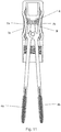
- an external force is applied to the proximal ends of the stems. This force tends to compress the spring (6) and force the applicator heads (4a, 4b) apart. This is depicted in figures 2b and 11 .
- the spring expands, pushing the proximal ends of the stems apart, expanding the flexible portions of the overcap, and forcing the applicator heads toward rest position.
- Figure 12 depicts an applicator in rest position.
- the lateral wall (7d) and flexible portions (7a, 7b) of the overcap (7) are separate components.
- the flexible portions are permanently assembled over the windows of the lateral wall.
- the perimeter (7i) of each flexible portions is permanently assembled to the perimeter (7j) of the window of the lateral wall.
- the perimeter of the flexible portions may be snap fitted or glued to the perimeter of lateral wall portions, but this type of assembly is relatively labor intensive.
- the rigid and flexible wall portions are formed using bi-injection molding techniques. This process is carried out by either simultaneously or successively injecting different molten materials into separate sections of a mold until the separate components meet to fill the mold.
- the material comprising the rigid wall of the overcap may be polyethylene, such as low density polyethylene, high density polyethylene, or blends of varying density polyethylene; polypropylene; polyvinylchloride; polyesters; polyamides; nylons; or blends of other plastics, such as a polycarbonate/polypropylene mixture.
- the rigid frame is composed of polypropylene.
- the flexible portions are preferably elastomeric or thermoplastic material, such as silicone, ethylene vinyl acetate copolymer (EVA), polyether amide block copolymer, polyester elastomer, ethylene propylene diene monomer rubber (EPDM), polyurethane, styrene butadiene styrene (SBS), styrene isoprene styrene, styrene ethylene-butylene styrene, styrene ethylene-propylene styrene, latex, and nitrile butadiene rubber.
- elastomeric or thermoplastic material such as silicone, ethylene vinyl acetate copolymer (EVA), polyether amide block copolymer, polyester elastomer, ethylene propylene diene monomer rubber (EPDM), polyurethane, styrene butadiene styrene (SBS), styrene is
- the overcap (7) also acts as a closure for the container (1) through its cooperating threads (7c), and provides optional, but preferred sealing features.
- the overcap when the overcap is screwed down onto the container, the bottom (7g) of the overcap comes to bear down on the flange (2g) of the wiper housing (2a), creating a seal between the flange and the overcap.
- preferred overcaps have a tapered surface (7h) above the threads. When the overcap is screwed down onto the container, then the tapered surface comes to bear against the beveled surface (2q) near the top of the wiper housing, thus forming another seal between the wiper housing and the overcap.
- the bi-injection molding process described above is also preferred because joining the flexible and rigid portions in this way ensures that there will be no air gaps in the finished overcap.
- the stems (3a, 3b) and applicator heads (4a, 4b) revolve around the longitudinal axis (A) of the neck (1 b). Because the stems contact the wiper (2b), the wiper rotates around the same axis.
- the wiper housing (2a) is prevented from rotating, as described above, so that the seal that the wiper housing makes with the neck of the container is not compromised.
- the applicator heads may be raised out of the reservoir. In doing so, the stems and applicator heads are wiped by the orifices (2m, 2n) of the wiper (2b).
- the applicator While in the grip of the applicator heads, the applicator is drawn along the surface, spreading product on the surface with constant pressure.
- a user will draw the applicator heads away from the eyelid, coating the eyelashes along the way until the applicator heads reach the end of the eyelashes and come off the lashes.
- the user may squeeze the flexible portions of the overcap to separate the applicator heads and repeat the process on the same of different lashes.
- the applicator can also be used without gripping a part of the body.
- the surfaces of the applicator heads that do not meet in rest position may be used according to their typical use. Thus, product may be spread evenly with the pincer grip, and then touched up in a more conventional fashion.
- each applicator head will be guided into one of the passageways (2k, 2l) of the wiper without having to apply any pressure to the flexible portions of the overcap.
- Figure 1 is a cross section of an applicator system according to one preferred embodiment of the present invention.
- the overcap (7) is fully seated on the container (1).
- the applicator heads (4a, 4b) are shown as separated, i.e. not fully in the rest position. This may happen if the wall (2p) between the two passageways (2k, 2l) of the wiper (2b) is sufficiently strong to hold the stems (3a, 3b) apart.
- some separation between the applicator heads is preferred, because it enables the entire applicator head to contact and receive product. Otherwise, those surfaces of the applicator heads that contact each other would have less product, and these are exactly the most important surfaces for applying product with the present applicator system.
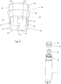
- the reservoir (10a) (and container 10) may be tapered outward, having a larger diameter at the bottom (10g) than at the neck (10b).
- the applicator heads could be made to expand to scrape the internal surface (10f) of the container. As the applicator heads are withdrawn from the reservoir, the walls would push back against the applicator heads, pushing them closer together until they reach the wiper.
- Container shapes are not limited to simple tapering, and a wide variety of shapes will be more efficiently evacuated with an applicator according to the present invention.
- the applicator heads of the present invention are especially able to scrape the internal surface of any cylindrically symmetric reservoir. Therefore, non-cylindrical reservoirs that have cylindrical symmetry are preferred when efficient evacuation is important.
- Such shapes may be regular, such as spheres, cones, and cylinders, but may also be an irregular solid of revolution.
- the applicator system thus described is particularly useful for making up hair. Also, although the invention has been described in terms of make up products, other products such as treatment products may be applied in the same manner.
- the tweezer applicator system described herein provides improvements of prior art applicators, especially those for applying mascara.
- the system may use a standard container of the type commonly used, and the container may be filled to conventional levels.
- the tweezer grip is achieved without the application of external pressure, which gives a consistent grip and more even application of product.
- the present applicator is able to evacuate more product from the container than prior art applicators, even for some non-cylindrical containers.
Claims (11)
- Ein pinzettenartiges Applikatorsystem, das Folgendes umfasst:- einen Behälter (1) mit einem Vorratsbehälter (1a) zum Aufnehmen eines Produkts (P), das auf einen Körper aufgetragen werden soll, sowie einen Hals (1b) mit einem Schraubgewinde (1d);- einen Abstreifer (2b), der in dem Hals (1b) des Behälters (1) derart gesichert ist, dass sich der Abstreifer (2b) frei dreht, und wobei der Abstreifer (2b) einen konisch zulaufenden unteren Abschnitt (2j) und zwei, durch den Abstreifer (2b) hindurchlaufende Kanäle (2k, 21) umfasst, die in zwei unteren Öffnungen (2m, 2n) enden, welche in den Vorratsbehälter (1a) führen;- eine mit Gewinde versehene Deckkappe (7), die um den Hals (1b) geschraubt werden kann und eine Seitenwand (7d) umfasst, die flexible Abschnitte (7a, 7b) aufweist, die zusammengedrückt werden können;- einen Drehpunkt (5), der in der Deckkappe (7) untergebracht und mit ihr starr verbunden ist und eine Achse (5c) umfasst;- zwei Schäfte (3a, 3b), wobei jeder Schaft ein proximales Ende (3e, 3f) und ein distales Ende (3c, 3d) umfasst, wobei jedes distale Ende (3c, 3d) einen Applikatorkopf (4a, 4b) trägt; jeder Schaft (3a, 3b) zwischen seinen proximalen (3e, 3f) und distalen (3c, 3d) Enden in einer Schwenkvorrichtung an der Achse (5c) angelenkt ist;- eine in dem Drehpunkt (5) untergebrachte Feder (6), die die proximalen Enden (3e, 3f) der Schäfte berührt und die proximalen Enden (3e, 3f) voneinander weg vorspannt;wobei:- durch Zusammendrücken der flexiblen Abschnitte (7a, 7b) der Deckkappe (7) eine äußere Kraft auf die proximalen Enden (3e, 3f) der Schäfte (3a, 3b) ausgeübt wird, die die Feder (6) zusammen- und die Applikatorköpfe (4a, 4b) auseinanderdrückt; und- wenn jeder Schaft (3a, 3b) durch einen der Kanäle (2k, 21) hindurch angeordnet ist, dann bewirkt das Schrauben der Deckkappe (7) um den Hals (1b), dass die Schäfte (3a, 3b) rotieren und sich der Abstreifer (2b) um die Längsachse des Halses (1b) dreht.
- Das pinzettenartige Applikatorsystem nach Anspruch 1, das ferner ein hohles Gehäuse für den Abstreifer (2a) umfasst, das einen oberen Abschnitt (2f) und einen unteren Abschnitt (2c) aufweist; wobei- der obere Abschnitt (2f) sich oberhalb des Halses (1b) des Behälters erstreckt;- der untere Abschnitt (2c) im Hals (1b) des Behälters befestigt ist;- der Abstreifer (2b) von dem unteren Abschnitt (2c) des Gehäuses für den Abstreifer (2a) so herabhängt, dass der Abstreifer (2b) in Bezug zu dem Gehäuse (2a) drehbar ist.
- Das pinzettenartige Applikatorsystem nach Anspruch 2, wobei das Gehäuse für den Abstreifer (2a) eine Feststellvorrichtung (2o) aufweist, die durch eine Kerbe (1e), die im Hals (1b) des Behälters (1) angebracht ist, verhindert, dass sich das Gehäuse für den Abstreifer (2a) dreht.
- Das pinzettenartige Applikatorsystem nach Anspruch 1, wobei die unteren Öffnungen (2m, 2n) des Abstreifers (2b) bemessen sind, um die Schäfte (3a, 3b) und Applikatorköpfe (4a, 4b) abzustreichen, wenn sie sich durch den Abstreifer (2b) hindurch bewegen.
- Das pinzettenartige Applikatorsystem nach Anspruch 1, wobei jeder Schaft (3a, 3b) mindestens einen Kragen (3g, 3h) aufweist, der in der Lage ist, die Achse (5c) in einer Schwenkvorrichtung aufzunehmen.
- Das pinzettenartige Applikatorsystem nach Anspruch 1, wobei jeder Schaft (3a, 3b) eine Nut (3i, 3j) zum Aufnehmen gegenüberliegender Enden der Feder (6) aufweist.
- Das pinzettenartige Applikatorsystem nach Anspruch 1, wobei die Applikatorköpfe (4a, 4b) aus Bürsten, Kämmen und Schwämmen ausgewählt sind.
- Das pinzettenartige Applikatorsystem nach Anspruch 7, wobei die Applikatorköpfe (4a, 4b) zum Auftragen von Mascara auf die Wimpern geeignet sind.
- Das pinzettenartige Applikatorsystem nach Anspruch 1, wobei der Drehpunkt (5) Folgendes umfasst:- einen oberen Abschnitt (5a), von dem ein Gehäuse (5e) für die Feder (6) herabhängt, und- zwei herabhängende, voneinander beabstandete Schenkel (5b), so dass die Achse (5c) fest zwischen den Schenkeln (5b) angebracht ist.
- Das pinzettenartige Applikatorsystem nach Anspruch 1, wobei der Behälter (1) nicht zylindrisch ist.
- Das pinzettenartige Applikatorsystem nach Anspruch 1, wobei der Vorratsbehälter (1a) ein Haarmittel enthält.
Applications Claiming Priority (2)
| Application Number | Priority Date | Filing Date | Title |
|---|---|---|---|
| US13/746,409 US8851775B2 (en) | 2013-01-22 | 2013-01-22 | Tweezer type package for cosmetic product application |
| PCT/US2013/078085 WO2014116390A1 (en) | 2013-01-22 | 2013-12-27 | Tweezer type package for cosmetic product application |
Publications (3)
| Publication Number | Publication Date |
|---|---|
| EP2948021A1 EP2948021A1 (de) | 2015-12-02 |
| EP2948021A4 EP2948021A4 (de) | 2016-08-17 |
| EP2948021B1 true EP2948021B1 (de) | 2017-06-28 |
Family
ID=51207791
Family Applications (1)
| Application Number | Title | Priority Date | Filing Date |
|---|---|---|---|
| EP13872784.7A Active EP2948021B1 (de) | 2013-01-22 | 2013-12-27 | Pinzettenartiges gehäuse zum auftragen eines kosmetikproduktes |
Country Status (8)
| Country | Link |
|---|---|
| US (1) | US8851775B2 (de) |
| EP (1) | EP2948021B1 (de) |
| JP (1) | JP5946593B2 (de) |
| KR (1) | KR101708137B1 (de) |
| AU (1) | AU2013375212B2 (de) |
| CA (1) | CA2896712C (de) |
| ES (1) | ES2641163T3 (de) |
| WO (1) | WO2014116390A1 (de) |
Families Citing this family (27)
| Publication number | Priority date | Publication date | Assignee | Title |
|---|---|---|---|---|
| US10441054B2 (en) | 2012-10-04 | 2019-10-15 | Lisa Hatch | Stabilized, precision, dual-brush eyelash application apparatus and method |
| WO2014055940A1 (en) | 2012-10-04 | 2014-04-10 | Lash Duet, Llc | Dual eyelash applicator with reverse action apparatus |
| US20150164210A1 (en) * | 2013-12-12 | 2015-06-18 | Jia Hsing Enterprise Co., Ltd. | Eyelash Brush |
| FR3026281B1 (fr) * | 2014-09-25 | 2018-08-24 | L'oreal | Organe d'application comportant deux parties assemblees. |
| KR101681315B1 (ko) | 2015-04-29 | 2016-11-30 | 주식회사 인터워크 코리아 | 속눈썹용 화장품 도포기 |
| US20160367013A1 (en) * | 2015-06-22 | 2016-12-22 | Melissa Arredondo | Active arm eyelash applicator |
| CN106307976A (zh) * | 2015-07-02 | 2017-01-11 | 洽兴包装工业(中国)有限公司 | 双头睫毛膏刷 |
| CN106307978A (zh) * | 2015-07-03 | 2017-01-11 | 洽兴包装工业(中国)有限公司 | 异形头涂抹装置 |
| KR101703698B1 (ko) * | 2015-07-06 | 2017-02-08 | (주)아모레퍼시픽 | 편심으로 형성된 솔대를 구비한 손가락 삽입 마스카라 용기 |
| KR101745357B1 (ko) | 2015-07-06 | 2017-06-12 | (주)아모레퍼시픽 | 탄성슬릿부를 구비한 손가락 삽입 마스카라 용기 |
| JP6734635B2 (ja) * | 2015-09-30 | 2020-08-05 | 株式会社吉野工業所 | 塗布具付容器 |
| US20170231368A1 (en) * | 2016-02-12 | 2017-08-17 | Maria A. NAVARRO | Mascara applicator for simultaneously curling and applying mascara to eyelashes and a storage system |
| KR101929286B1 (ko) * | 2016-07-05 | 2018-12-14 | (주)에프에스케이컬러 | 하부 회전 와이퍼가 구비된 마스카라 용기 |
| JP2018064791A (ja) * | 2016-10-20 | 2018-04-26 | ロレアル | 化粧用製品を保管し、塗布するためのアプリケータおよび組立体 |
| KR102351643B1 (ko) * | 2017-01-03 | 2022-01-17 | 주식회사 엘지생활건강 | 마스카라 |
| JP6639023B2 (ja) * | 2017-01-31 | 2020-02-05 | 稔 兼松 | マスカラ塗布具製品 |
| KR101893891B1 (ko) * | 2017-03-29 | 2018-08-31 | 안동과학대학교 산학협력단 | 멀티 브러시를 갖는 화장품 용기 |
| US10849405B2 (en) * | 2017-09-20 | 2020-12-01 | Elc Management Llc | Cap and vial applicator system for applying two cosmetic products |
| KR101896685B1 (ko) * | 2018-03-26 | 2018-09-10 | 주식회사 엘지생활건강 | 마스카라 |
| KR102557203B1 (ko) * | 2018-04-20 | 2023-07-21 | 주식회사 인터워크 코리아 | 속눈썹용 화장품 도포기 |
| USD898290S1 (en) * | 2018-07-09 | 2020-10-06 | Jd Holding | Combined tweezer and brush |
| JP7300323B2 (ja) * | 2019-06-24 | 2023-06-29 | 花王株式会社 | 塗布具付き染毛料容器 |
| US11877641B2 (en) * | 2020-08-31 | 2024-01-23 | L'oreal | Applicator with expanding surface area mechanism |
| DE202021103262U1 (de) | 2021-06-17 | 2021-08-02 | KK (Kunert Kosmetik) UG (haftungsbeschränkt) | Wimperntuschensystem, Applikator und Depoteinheit zum Speichern und Auftragen von Wimperntusche |
| WO2022263643A1 (de) | 2021-06-17 | 2022-12-22 | KK (Kunert Kosmetik) UG (haftungsbeschränkt) | Wimperntuschensystem, applikator und depoteinheit zum speichern und auftragen von wimperntusche |
| DE102021115712A1 (de) | 2021-06-17 | 2022-12-22 | KK (Kunert Kosmetik) UG (haftungsbeschränkt) | Wimperntuschensystem, Applikator und Depoteinheit zum Speichern und Auftragen von Wimperntusche |
| USD1015635S1 (en) * | 2021-10-28 | 2024-02-20 | Cecilia Paige | Tweezer brush combination |
Family Cites Families (22)
| Publication number | Priority date | Publication date | Assignee | Title |
|---|---|---|---|---|
| US2022896A (en) * | 1935-01-28 | 1935-12-03 | Robert R Nathans | Eyelash applicator and curler |
| US2136779A (en) | 1937-11-04 | 1938-11-15 | Henry J Bednar | Eyelash darkener |
| GB804192A (en) * | 1956-12-17 | 1958-11-12 | Ernest Norland | Mascara applicator |
| US2908923A (en) * | 1957-12-23 | 1959-10-20 | Edward E Schlechter | Lens cleaning device |
| JPS5757510A (en) * | 1980-09-22 | 1982-04-06 | Kanebo Ltd | Mascara coating tool |
| US4458701A (en) | 1983-03-21 | 1984-07-10 | Linda Holland | Mascara applicator |
| US5052839A (en) | 1986-03-06 | 1991-10-01 | Pettengill Edwin R | Mascara applicator |
| US5007442A (en) | 1988-01-11 | 1991-04-16 | Hirzel Suzy C | Double blocking members sealing a single opening means |
| US5137387A (en) | 1991-06-11 | 1992-08-11 | Maybe Holding Co., Inc. | Cosmetic applicator with rotary wiping system |
| US5172992A (en) | 1992-03-09 | 1992-12-22 | Risdon Corporation | Mascara container with stirrer |
| DE9316704U1 (de) | 1993-11-02 | 1994-01-13 | Geka Brush Georg Karl Gmbh | Mascara-Bürstchen |
| US5611361A (en) | 1995-06-14 | 1997-03-18 | Revlon Consumer Products Corporation | Mascara application system |
| US5676480A (en) | 1996-04-05 | 1997-10-14 | Tosto; Nada | Hair dye applicating apparatus |
| US5700100A (en) | 1997-02-20 | 1997-12-23 | Risdon Corporation | Mascara container having a stirrer and a separate wiper |
| US6120202A (en) * | 1999-06-21 | 2000-09-19 | Donsky; Robin | Nail polish applicator bottle |
| US6325071B1 (en) | 2000-02-17 | 2001-12-04 | G.H.B. Enterprises | Dual blade mascara application system |
| US6508603B1 (en) | 2000-11-17 | 2003-01-21 | The Bridgeport Metal Goods Manufacturing Company | Mascara brush configured for loading from sidewall of container |
| WO2004077987A1 (en) | 2003-03-05 | 2004-09-16 | Laline International Sarl | Mascara applicator with movable arms |
| JP2007020793A (ja) * | 2005-07-14 | 2007-02-01 | Mitsubishi Pencil Co Ltd | 化粧料塗布具及び塗布容器 |
| US7997820B2 (en) * | 2009-03-31 | 2011-08-16 | Elc Management Llc | Multi-applicator package with single handle |
| DE102009057026A1 (de) | 2009-12-04 | 2011-06-09 | Geka Gmbh | Kosmetikapplikator, insbesondere Mascaraapplikator sowie ein Kosmetikprodukt |
| US20110250003A1 (en) | 2010-04-12 | 2011-10-13 | Rnd Group Llc | Double type cosmetics package |
-
2013
- 2013-01-22 US US13/746,409 patent/US8851775B2/en active Active
- 2013-12-27 JP JP2015553743A patent/JP5946593B2/ja active Active
- 2013-12-27 ES ES13872784.7T patent/ES2641163T3/es active Active
- 2013-12-27 WO PCT/US2013/078085 patent/WO2014116390A1/en active Application Filing
- 2013-12-27 EP EP13872784.7A patent/EP2948021B1/de active Active
- 2013-12-27 AU AU2013375212A patent/AU2013375212B2/en active Active
- 2013-12-27 CA CA2896712A patent/CA2896712C/en active Active
- 2013-12-27 KR KR1020157019287A patent/KR101708137B1/ko active IP Right Grant
Also Published As
| Publication number | Publication date |
|---|---|
| EP2948021A4 (de) | 2016-08-17 |
| AU2013375212B2 (en) | 2016-08-04 |
| JP2016503713A (ja) | 2016-02-08 |
| CA2896712A1 (en) | 2014-07-31 |
| AU2013375212A1 (en) | 2015-08-13 |
| US20140205357A1 (en) | 2014-07-24 |
| KR20150096507A (ko) | 2015-08-24 |
| CA2896712C (en) | 2017-10-10 |
| ES2641163T3 (es) | 2017-11-08 |
| KR101708137B1 (ko) | 2017-02-17 |
| WO2014116390A1 (en) | 2014-07-31 |
| JP5946593B2 (ja) | 2016-07-06 |
| US8851775B2 (en) | 2014-10-07 |
| EP2948021A1 (de) | 2015-12-02 |
Similar Documents
| Publication | Publication Date | Title |
|---|---|---|
| EP2948021B1 (de) | Pinzettenartiges gehäuse zum auftragen eines kosmetikproduktes | |
| US8292529B2 (en) | Dispenser and method for dispensing fluids | |
| EP2285250B1 (de) | Verpackung und applikatorvorrichtung, insbesondere für mascara | |
| AU757128B2 (en) | Flexible wall cosmetic container | |
| JPH08173237A (ja) | メーキャップ製品の保存および塗布用装置 | |
| JP2007167615A (ja) | 物質を毛に塗布するための装置 | |
| JP2008508983A (ja) | 化粧組成物を貯蔵かつ施与するための装置 | |
| US11439221B2 (en) | Stabilized, precision, dual-brush eyelash application apparatus and method | |
| JP2005253985A (ja) | 化粧品のアプリケータ | |
| US7229228B2 (en) | Applicator dispenser of a paste cosmetic product, typically a mascara | |
| JP2007160114A (ja) | 特にマニキュア液用の製品保留部を備える塗布具 | |
| EP1474017B1 (de) | Verbesserte auftragungsmaterialpackung und herstellungsverfahren | |
| JP2004065467A (ja) | 高粘度流動性化粧品を塗布するための化粧用具 | |
| KR20150124946A (ko) | 화장료 조성물을 도포하는 장치 | |
| US20160367013A1 (en) | Active arm eyelash applicator | |
| US10537164B1 (en) | Cosmetic container with anti-contamination function for wiper | |
| JP4102645B2 (ja) | 貯蔵・塗布ユニット | |
| KR102180414B1 (ko) | 화장 제품용 힌지식 도포기 및 관련 포장 및 도포 어셈블리 | |
| JP2007307314A (ja) | 液状化粧料容器 | |
| JP2006263233A (ja) | 液状化粧料容器 |
Legal Events
| Date | Code | Title | Description |
|---|---|---|---|
| PUAI | Public reference made under article 153(3) epc to a published international application that has entered the european phase |
Free format text: ORIGINAL CODE: 0009012 |
|
| 17P | Request for examination filed |
Effective date: 20150813 |
|
| AK | Designated contracting states |
Kind code of ref document: A1 Designated state(s): AL AT BE BG CH CY CZ DE DK EE ES FI FR GB GR HR HU IE IS IT LI LT LU LV MC MK MT NL NO PL PT RO RS SE SI SK SM TR |
|
| AX | Request for extension of the european patent |
Extension state: BA ME |
|
| DAX | Request for extension of the european patent (deleted) | ||
| A4 | Supplementary search report drawn up and despatched |
Effective date: 20160714 |
|
| RIC1 | Information provided on ipc code assigned before grant |
Ipc: B65D 51/32 20060101ALI20160708BHEP Ipc: A45D 34/04 20060101AFI20160708BHEP |
|
| GRAP | Despatch of communication of intention to grant a patent |
Free format text: ORIGINAL CODE: EPIDOSNIGR1 |
|
| STAA | Information on the status of an ep patent application or granted ep patent |
Free format text: STATUS: GRANT OF PATENT IS INTENDED |
|
| INTG | Intention to grant announced |
Effective date: 20170126 |
|
| GRAS | Grant fee paid |
Free format text: ORIGINAL CODE: EPIDOSNIGR3 |
|
| GRAA | (expected) grant |
Free format text: ORIGINAL CODE: 0009210 |
|
| STAA | Information on the status of an ep patent application or granted ep patent |
Free format text: STATUS: THE PATENT HAS BEEN GRANTED |
|
| AK | Designated contracting states |
Kind code of ref document: B1 Designated state(s): AL AT BE BG CH CY CZ DE DK EE ES FI FR GB GR HR HU IE IS IT LI LT LU LV MC MK MT NL NO PL PT RO RS SE SI SK SM TR |
|
| REG | Reference to a national code |
Ref country code: GB Ref legal event code: FG4D |
|
| REG | Reference to a national code |
Ref country code: CH Ref legal event code: EP |
|
| REG | Reference to a national code |
Ref country code: AT Ref legal event code: REF Ref document number: 904061 Country of ref document: AT Kind code of ref document: T Effective date: 20170715 |
|
| REG | Reference to a national code |
Ref country code: IE Ref legal event code: FG4D |
|
| REG | Reference to a national code |
Ref country code: DE Ref legal event code: R096 Ref document number: 602013023018 Country of ref document: DE |
|
| PG25 | Lapsed in a contracting state [announced via postgrant information from national office to epo] |
Ref country code: GR Free format text: LAPSE BECAUSE OF FAILURE TO SUBMIT A TRANSLATION OF THE DESCRIPTION OR TO PAY THE FEE WITHIN THE PRESCRIBED TIME-LIMIT Effective date: 20170929 Ref country code: HR Free format text: LAPSE BECAUSE OF FAILURE TO SUBMIT A TRANSLATION OF THE DESCRIPTION OR TO PAY THE FEE WITHIN THE PRESCRIBED TIME-LIMIT Effective date: 20170628 Ref country code: LT Free format text: LAPSE BECAUSE OF FAILURE TO SUBMIT A TRANSLATION OF THE DESCRIPTION OR TO PAY THE FEE WITHIN THE PRESCRIBED TIME-LIMIT Effective date: 20170628 Ref country code: NO Free format text: LAPSE BECAUSE OF FAILURE TO SUBMIT A TRANSLATION OF THE DESCRIPTION OR TO PAY THE FEE WITHIN THE PRESCRIBED TIME-LIMIT Effective date: 20170928 Ref country code: FI Free format text: LAPSE BECAUSE OF FAILURE TO SUBMIT A TRANSLATION OF THE DESCRIPTION OR TO PAY THE FEE WITHIN THE PRESCRIBED TIME-LIMIT Effective date: 20170628 |
|
| REG | Reference to a national code |
Ref country code: NL Ref legal event code: MP Effective date: 20170628 |
|
| REG | Reference to a national code |
Ref country code: ES Ref legal event code: FG2A Ref document number: 2641163 Country of ref document: ES Kind code of ref document: T3 Effective date: 20171108 |
|
| REG | Reference to a national code |
Ref country code: LT Ref legal event code: MG4D |
|
| REG | Reference to a national code |
Ref country code: AT Ref legal event code: MK05 Ref document number: 904061 Country of ref document: AT Kind code of ref document: T Effective date: 20170628 |
|
| REG | Reference to a national code |
Ref country code: FR Ref legal event code: PLFP Year of fee payment: 5 |
|
| PG25 | Lapsed in a contracting state [announced via postgrant information from national office to epo] |
Ref country code: RS Free format text: LAPSE BECAUSE OF FAILURE TO SUBMIT A TRANSLATION OF THE DESCRIPTION OR TO PAY THE FEE WITHIN THE PRESCRIBED TIME-LIMIT Effective date: 20170628 Ref country code: LV Free format text: LAPSE BECAUSE OF FAILURE TO SUBMIT A TRANSLATION OF THE DESCRIPTION OR TO PAY THE FEE WITHIN THE PRESCRIBED TIME-LIMIT Effective date: 20170628 Ref country code: SE Free format text: LAPSE BECAUSE OF FAILURE TO SUBMIT A TRANSLATION OF THE DESCRIPTION OR TO PAY THE FEE WITHIN THE PRESCRIBED TIME-LIMIT Effective date: 20170628 Ref country code: NL Free format text: LAPSE BECAUSE OF FAILURE TO SUBMIT A TRANSLATION OF THE DESCRIPTION OR TO PAY THE FEE WITHIN THE PRESCRIBED TIME-LIMIT Effective date: 20170628 Ref country code: BG Free format text: LAPSE BECAUSE OF FAILURE TO SUBMIT A TRANSLATION OF THE DESCRIPTION OR TO PAY THE FEE WITHIN THE PRESCRIBED TIME-LIMIT Effective date: 20170928 |
|
| PG25 | Lapsed in a contracting state [announced via postgrant information from national office to epo] |
Ref country code: AT Free format text: LAPSE BECAUSE OF FAILURE TO SUBMIT A TRANSLATION OF THE DESCRIPTION OR TO PAY THE FEE WITHIN THE PRESCRIBED TIME-LIMIT Effective date: 20170628 Ref country code: CZ Free format text: LAPSE BECAUSE OF FAILURE TO SUBMIT A TRANSLATION OF THE DESCRIPTION OR TO PAY THE FEE WITHIN THE PRESCRIBED TIME-LIMIT Effective date: 20170628 Ref country code: RO Free format text: LAPSE BECAUSE OF FAILURE TO SUBMIT A TRANSLATION OF THE DESCRIPTION OR TO PAY THE FEE WITHIN THE PRESCRIBED TIME-LIMIT Effective date: 20170628 Ref country code: EE Free format text: LAPSE BECAUSE OF FAILURE TO SUBMIT A TRANSLATION OF THE DESCRIPTION OR TO PAY THE FEE WITHIN THE PRESCRIBED TIME-LIMIT Effective date: 20170628 Ref country code: SK Free format text: LAPSE BECAUSE OF FAILURE TO SUBMIT A TRANSLATION OF THE DESCRIPTION OR TO PAY THE FEE WITHIN THE PRESCRIBED TIME-LIMIT Effective date: 20170628 |
|
| PG25 | Lapsed in a contracting state [announced via postgrant information from national office to epo] |
Ref country code: SM Free format text: LAPSE BECAUSE OF FAILURE TO SUBMIT A TRANSLATION OF THE DESCRIPTION OR TO PAY THE FEE WITHIN THE PRESCRIBED TIME-LIMIT Effective date: 20170628 Ref country code: IS Free format text: LAPSE BECAUSE OF FAILURE TO SUBMIT A TRANSLATION OF THE DESCRIPTION OR TO PAY THE FEE WITHIN THE PRESCRIBED TIME-LIMIT Effective date: 20171028 Ref country code: PL Free format text: LAPSE BECAUSE OF FAILURE TO SUBMIT A TRANSLATION OF THE DESCRIPTION OR TO PAY THE FEE WITHIN THE PRESCRIBED TIME-LIMIT Effective date: 20170628 |
|
| REG | Reference to a national code |
Ref country code: DE Ref legal event code: R097 Ref document number: 602013023018 Country of ref document: DE |
|
| PG25 | Lapsed in a contracting state [announced via postgrant information from national office to epo] |
Ref country code: DK Free format text: LAPSE BECAUSE OF FAILURE TO SUBMIT A TRANSLATION OF THE DESCRIPTION OR TO PAY THE FEE WITHIN THE PRESCRIBED TIME-LIMIT Effective date: 20170628 |
|
| PLBE | No opposition filed within time limit |
Free format text: ORIGINAL CODE: 0009261 |
|
| STAA | Information on the status of an ep patent application or granted ep patent |
Free format text: STATUS: NO OPPOSITION FILED WITHIN TIME LIMIT |
|
| 26N | No opposition filed |
Effective date: 20180329 |
|
| REG | Reference to a national code |
Ref country code: CH Ref legal event code: PL |
|
| PG25 | Lapsed in a contracting state [announced via postgrant information from national office to epo] |
Ref country code: SI Free format text: LAPSE BECAUSE OF FAILURE TO SUBMIT A TRANSLATION OF THE DESCRIPTION OR TO PAY THE FEE WITHIN THE PRESCRIBED TIME-LIMIT Effective date: 20170628 |
|
| REG | Reference to a national code |
Ref country code: IE Ref legal event code: MM4A |
|
| PG25 | Lapsed in a contracting state [announced via postgrant information from national office to epo] |
Ref country code: LU Free format text: LAPSE BECAUSE OF NON-PAYMENT OF DUE FEES Effective date: 20171227 Ref country code: MT Free format text: LAPSE BECAUSE OF NON-PAYMENT OF DUE FEES Effective date: 20171227 |
|
| REG | Reference to a national code |
Ref country code: BE Ref legal event code: MM Effective date: 20171231 |
|
| PG25 | Lapsed in a contracting state [announced via postgrant information from national office to epo] |
Ref country code: IE Free format text: LAPSE BECAUSE OF NON-PAYMENT OF DUE FEES Effective date: 20171227 |
|
| PG25 | Lapsed in a contracting state [announced via postgrant information from national office to epo] |
Ref country code: LI Free format text: LAPSE BECAUSE OF NON-PAYMENT OF DUE FEES Effective date: 20171231 Ref country code: BE Free format text: LAPSE BECAUSE OF NON-PAYMENT OF DUE FEES Effective date: 20171231 Ref country code: CH Free format text: LAPSE BECAUSE OF NON-PAYMENT OF DUE FEES Effective date: 20171231 |
|
| PG25 | Lapsed in a contracting state [announced via postgrant information from national office to epo] |
Ref country code: HU Free format text: LAPSE BECAUSE OF FAILURE TO SUBMIT A TRANSLATION OF THE DESCRIPTION OR TO PAY THE FEE WITHIN THE PRESCRIBED TIME-LIMIT; INVALID AB INITIO Effective date: 20131227 Ref country code: MC Free format text: LAPSE BECAUSE OF FAILURE TO SUBMIT A TRANSLATION OF THE DESCRIPTION OR TO PAY THE FEE WITHIN THE PRESCRIBED TIME-LIMIT Effective date: 20170628 |
|
| PG25 | Lapsed in a contracting state [announced via postgrant information from national office to epo] |
Ref country code: CY Free format text: LAPSE BECAUSE OF FAILURE TO SUBMIT A TRANSLATION OF THE DESCRIPTION OR TO PAY THE FEE WITHIN THE PRESCRIBED TIME-LIMIT Effective date: 20170628 |
|
| PG25 | Lapsed in a contracting state [announced via postgrant information from national office to epo] |
Ref country code: MK Free format text: LAPSE BECAUSE OF FAILURE TO SUBMIT A TRANSLATION OF THE DESCRIPTION OR TO PAY THE FEE WITHIN THE PRESCRIBED TIME-LIMIT Effective date: 20170628 |
|
| PG25 | Lapsed in a contracting state [announced via postgrant information from national office to epo] |
Ref country code: TR Free format text: LAPSE BECAUSE OF FAILURE TO SUBMIT A TRANSLATION OF THE DESCRIPTION OR TO PAY THE FEE WITHIN THE PRESCRIBED TIME-LIMIT Effective date: 20170628 |
|
| PG25 | Lapsed in a contracting state [announced via postgrant information from national office to epo] |
Ref country code: PT Free format text: LAPSE BECAUSE OF FAILURE TO SUBMIT A TRANSLATION OF THE DESCRIPTION OR TO PAY THE FEE WITHIN THE PRESCRIBED TIME-LIMIT Effective date: 20170628 |
|
| PG25 | Lapsed in a contracting state [announced via postgrant information from national office to epo] |
Ref country code: AL Free format text: LAPSE BECAUSE OF FAILURE TO SUBMIT A TRANSLATION OF THE DESCRIPTION OR TO PAY THE FEE WITHIN THE PRESCRIBED TIME-LIMIT Effective date: 20170628 |
|
| STAA | Information on the status of an ep patent application or granted ep patent |
Free format text: STATUS: NO OPPOSITION FILED WITHIN TIME LIMIT |
|
| PGFP | Annual fee paid to national office [announced via postgrant information from national office to epo] |
Ref country code: DE Payment date: 20221122 Year of fee payment: 10 |
|
| PGFP | Annual fee paid to national office [announced via postgrant information from national office to epo] |
Ref country code: ES Payment date: 20230102 Year of fee payment: 10 |
|
| PGFP | Annual fee paid to national office [announced via postgrant information from national office to epo] |
Ref country code: GB Payment date: 20231219 Year of fee payment: 11 |
|
| PGFP | Annual fee paid to national office [announced via postgrant information from national office to epo] |
Ref country code: IT Payment date: 20231221 Year of fee payment: 11 Ref country code: FR Payment date: 20231226 Year of fee payment: 11 |