EP2945397B1 - Module de haut-parleur pour dispositif mobile et dispositif mobile ayant une structure de rayonnement de conduite - Google Patents
Module de haut-parleur pour dispositif mobile et dispositif mobile ayant une structure de rayonnement de conduite Download PDFInfo
- Publication number
- EP2945397B1 EP2945397B1 EP15174495.0A EP15174495A EP2945397B1 EP 2945397 B1 EP2945397 B1 EP 2945397B1 EP 15174495 A EP15174495 A EP 15174495A EP 2945397 B1 EP2945397 B1 EP 2945397B1
- Authority
- EP
- European Patent Office
- Prior art keywords
- duct
- opening surface
- speaker
- speaker module
- mobile device
- Prior art date
- Legal status (The legal status is an assumption and is not a legal conclusion. Google has not performed a legal analysis and makes no representation as to the accuracy of the status listed.)
- Active
Links
Images


Classifications
-
- H—ELECTRICITY
- H04—ELECTRIC COMMUNICATION TECHNIQUE
- H04R—LOUDSPEAKERS, MICROPHONES, GRAMOPHONE PICK-UPS OR LIKE ACOUSTIC ELECTROMECHANICAL TRANSDUCERS; DEAF-AID SETS; PUBLIC ADDRESS SYSTEMS
- H04R9/00—Transducers of moving-coil, moving-strip, or moving-wire type
- H04R9/06—Loudspeakers
-
- H—ELECTRICITY
- H04—ELECTRIC COMMUNICATION TECHNIQUE
- H04R—LOUDSPEAKERS, MICROPHONES, GRAMOPHONE PICK-UPS OR LIKE ACOUSTIC ELECTROMECHANICAL TRANSDUCERS; DEAF-AID SETS; PUBLIC ADDRESS SYSTEMS
- H04R1/00—Details of transducers, loudspeakers or microphones
- H04R1/20—Arrangements for obtaining desired frequency or directional characteristics
- H04R1/22—Arrangements for obtaining desired frequency or directional characteristics for obtaining desired frequency characteristic only
- H04R1/28—Transducer mountings or enclosures modified by provision of mechanical or acoustic impedances, e.g. resonator, damping means
- H04R1/2869—Reduction of undesired resonances, i.e. standing waves within enclosure, or of undesired vibrations, i.e. of the enclosure itself
- H04R1/2876—Reduction of undesired resonances, i.e. standing waves within enclosure, or of undesired vibrations, i.e. of the enclosure itself by means of damping material, e.g. as cladding
- H04R1/288—Reduction of undesired resonances, i.e. standing waves within enclosure, or of undesired vibrations, i.e. of the enclosure itself by means of damping material, e.g. as cladding for loudspeaker transducers
-
- H—ELECTRICITY
- H04—ELECTRIC COMMUNICATION TECHNIQUE
- H04M—TELEPHONIC COMMUNICATION
- H04M1/00—Substation equipment, e.g. for use by subscribers
- H04M1/02—Constructional features of telephone sets
- H04M1/03—Constructional features of telephone transmitters or receivers, e.g. telephone hand-sets
- H04M1/035—Improving the acoustic characteristics by means of constructional features of the housing, e.g. ribs, walls, resonating chambers or cavities
-
- H—ELECTRICITY
- H04—ELECTRIC COMMUNICATION TECHNIQUE
- H04R—LOUDSPEAKERS, MICROPHONES, GRAMOPHONE PICK-UPS OR LIKE ACOUSTIC ELECTROMECHANICAL TRANSDUCERS; DEAF-AID SETS; PUBLIC ADDRESS SYSTEMS
- H04R1/00—Details of transducers, loudspeakers or microphones
-
- H—ELECTRICITY
- H04—ELECTRIC COMMUNICATION TECHNIQUE
- H04R—LOUDSPEAKERS, MICROPHONES, GRAMOPHONE PICK-UPS OR LIKE ACOUSTIC ELECTROMECHANICAL TRANSDUCERS; DEAF-AID SETS; PUBLIC ADDRESS SYSTEMS
- H04R1/00—Details of transducers, loudspeakers or microphones
- H04R1/02—Casings; Cabinets ; Supports therefor; Mountings therein
- H04R1/023—Screens for loudspeakers
-
- H—ELECTRICITY
- H04—ELECTRIC COMMUNICATION TECHNIQUE
- H04R—LOUDSPEAKERS, MICROPHONES, GRAMOPHONE PICK-UPS OR LIKE ACOUSTIC ELECTROMECHANICAL TRANSDUCERS; DEAF-AID SETS; PUBLIC ADDRESS SYSTEMS
- H04R1/00—Details of transducers, loudspeakers or microphones
- H04R1/02—Casings; Cabinets ; Supports therefor; Mountings therein
- H04R1/025—Arrangements for fixing loudspeaker transducers, e.g. in a box, furniture
-
- H—ELECTRICITY
- H04—ELECTRIC COMMUNICATION TECHNIQUE
- H04R—LOUDSPEAKERS, MICROPHONES, GRAMOPHONE PICK-UPS OR LIKE ACOUSTIC ELECTROMECHANICAL TRANSDUCERS; DEAF-AID SETS; PUBLIC ADDRESS SYSTEMS
- H04R1/00—Details of transducers, loudspeakers or microphones
- H04R1/08—Mouthpieces; Microphones; Attachments therefor
- H04R1/083—Special constructions of mouthpieces
- H04R1/086—Protective screens, e.g. all weather or wind screens
-
- H—ELECTRICITY
- H04—ELECTRIC COMMUNICATION TECHNIQUE
- H04R—LOUDSPEAKERS, MICROPHONES, GRAMOPHONE PICK-UPS OR LIKE ACOUSTIC ELECTROMECHANICAL TRANSDUCERS; DEAF-AID SETS; PUBLIC ADDRESS SYSTEMS
- H04R1/00—Details of transducers, loudspeakers or microphones
- H04R1/20—Arrangements for obtaining desired frequency or directional characteristics
- H04R1/22—Arrangements for obtaining desired frequency or directional characteristics for obtaining desired frequency characteristic only
- H04R1/28—Transducer mountings or enclosures modified by provision of mechanical or acoustic impedances, e.g. resonator, damping means
- H04R1/2807—Enclosures comprising vibrating or resonating arrangements
- H04R1/2811—Enclosures comprising vibrating or resonating arrangements for loudspeaker transducers
-
- H—ELECTRICITY
- H04—ELECTRIC COMMUNICATION TECHNIQUE
- H04R—LOUDSPEAKERS, MICROPHONES, GRAMOPHONE PICK-UPS OR LIKE ACOUSTIC ELECTROMECHANICAL TRANSDUCERS; DEAF-AID SETS; PUBLIC ADDRESS SYSTEMS
- H04R1/00—Details of transducers, loudspeakers or microphones
- H04R1/20—Arrangements for obtaining desired frequency or directional characteristics
- H04R1/22—Arrangements for obtaining desired frequency or directional characteristics for obtaining desired frequency characteristic only
- H04R1/28—Transducer mountings or enclosures modified by provision of mechanical or acoustic impedances, e.g. resonator, damping means
- H04R1/2807—Enclosures comprising vibrating or resonating arrangements
- H04R1/2853—Enclosures comprising vibrating or resonating arrangements using an acoustic labyrinth or a transmission line
- H04R1/2857—Enclosures comprising vibrating or resonating arrangements using an acoustic labyrinth or a transmission line for loudspeaker transducers
-
- H—ELECTRICITY
- H04—ELECTRIC COMMUNICATION TECHNIQUE
- H04R—LOUDSPEAKERS, MICROPHONES, GRAMOPHONE PICK-UPS OR LIKE ACOUSTIC ELECTROMECHANICAL TRANSDUCERS; DEAF-AID SETS; PUBLIC ADDRESS SYSTEMS
- H04R1/00—Details of transducers, loudspeakers or microphones
- H04R1/20—Arrangements for obtaining desired frequency or directional characteristics
- H04R1/32—Arrangements for obtaining desired frequency or directional characteristics for obtaining desired directional characteristic only
- H04R1/34—Arrangements for obtaining desired frequency or directional characteristics for obtaining desired directional characteristic only by using a single transducer with sound reflecting, diffracting, directing or guiding means
- H04R1/345—Arrangements for obtaining desired frequency or directional characteristics for obtaining desired directional characteristic only by using a single transducer with sound reflecting, diffracting, directing or guiding means for loudspeakers
-
- H—ELECTRICITY
- H04—ELECTRIC COMMUNICATION TECHNIQUE
- H04R—LOUDSPEAKERS, MICROPHONES, GRAMOPHONE PICK-UPS OR LIKE ACOUSTIC ELECTROMECHANICAL TRANSDUCERS; DEAF-AID SETS; PUBLIC ADDRESS SYSTEMS
- H04R9/00—Transducers of moving-coil, moving-strip, or moving-wire type
- H04R9/02—Details
-
- H—ELECTRICITY
- H04—ELECTRIC COMMUNICATION TECHNIQUE
- H04R—LOUDSPEAKERS, MICROPHONES, GRAMOPHONE PICK-UPS OR LIKE ACOUSTIC ELECTROMECHANICAL TRANSDUCERS; DEAF-AID SETS; PUBLIC ADDRESS SYSTEMS
- H04R2400/00—Loudspeakers
- H04R2400/11—Aspects regarding the frame of loudspeaker transducers
-
- H—ELECTRICITY
- H04—ELECTRIC COMMUNICATION TECHNIQUE
- H04R—LOUDSPEAKERS, MICROPHONES, GRAMOPHONE PICK-UPS OR LIKE ACOUSTIC ELECTROMECHANICAL TRANSDUCERS; DEAF-AID SETS; PUBLIC ADDRESS SYSTEMS
- H04R2499/00—Aspects covered by H04R or H04S not otherwise provided for in their subgroups
- H04R2499/10—General applications
- H04R2499/11—Transducers incorporated or for use in hand-held devices, e.g. mobile phones, PDA's, camera's
Definitions
- the present invention relates to a speaker module for a mobile device and a mobile device having a duct radiation structure. More particularly, the present invention relates to a speaker module for a mobile device and a mobile device having a duct radiation structure that can improve a sound performance by changing a shape of an opening surface of a duct to which a protection member for preventing a foreign substance from being injected is attached.
- a recent mobile device performs mobile convergence including a function of other terminals as well as each traditional intrinsic function.
- a recent mobile communication terminal provides a multimedia function such as a television viewing function (e.g., mobile broadcasting such as Digital Multimedia Broadcasting (DMB) or Digital Video Broadcasting (DVB)), a music reproduction function (e.g., Motion Picture Experts Group (MPEG) Audio Layer-3 (MP3)), and a moving picture reproduction function, in addition to a general communication function such as voice communication and a character messaging service.
- DMB Digital Multimedia Broadcasting
- DVD Digital Video Broadcasting
- MPEG Motion Picture Experts Group Audio Layer-3
- MP3 Motion Picture Experts Group Audio Layer-3
- FIGs. 1A and 1B are a perspective view and a cross-sectional view illustrating an external appearance and a section of a speaker module having a duct radiation structure according to the related art.
- a speaker module 10 having a duct radiation structure includes a speaker 14 for outputting a sound signal, a body 11 in which the speaker 14 is mounted, a duct 12 extended from one surface of the body 11 for guiding a sound signal of the speaker 14 to be radiated to one surface, a soundproof member 15 attached to a wall of the duct 12, and a protection member 13 attached to the soundproof member 15 for preventing a foreign substance from entering the speaker module 10. It is preferable that the speaker module 10 has a size to improve a sound performance.
- a size of the speaker module 10 is limited by the available space in the mobile device.
- a size of the duct 12 in which a sound signal is radiated is further limited. In this way, as a size of the duct 12 is limited, the speaker module 10 has difficulty in securing a satisfactory sound performance.
- the protection member 13 for preventing a foreign substance from being injected is attached, it becomes difficult for the speaker module 10 to provide a satisfactory sound performance due to a sound pressure decrease by the protection member 13.
- JP-2007/256572-A discloses an electro-optical apparatus comprising: a display section including a display region; and sounding bodies.
- the sounding bodies include: speakers in which the sounding bodies are arranged so as to overlap with the display region on a plane view; and sound releasing holes which release sound output by the speakers.
- the plurality of sound releasing holes for composing the plurality of sounding bodies are arranged in the peripheral section located outside the plane view of the display region, along one edge of the display area.
- EP-1379101-A1 discloses a communication terminal comprising a housing carrying therein a radio antenna element, a speaker, and a chamber acting as an electromagnetic resonance cavity for the antenna and as an acoustic resonance cavity for the speaker.
- Said speaker is mounted inside said chamber and is coupled to the outside of said housing through a sound channel.
- the terminal comprises a user interface on a front side of the housing, and in that said speaker is placed behind said user interface as seen from said front side, with the sound channel extending from a channel inlet at said speaker to a channel front outlet at said front side.
- a mobile device comprising: a speaker module; a body to which the speaker module is fastened; and a protection member; wherein the speaker module comprises: a speaker configured to output a sound signal; a speaker module body to which the speaker is mounted; and a duct defining an opening surface for radiating a sound signal output from the speaker to outside of the speaker module, the duct being configured to guide a sound signal output from the speaker to the opening surface of the duct, wherein the opening surface is tilted relative to an extending direction of the duct; wherein the body of the mobile device includes a connecting structure having an opening surface configured to match the opening surface of the duct to radiate a sound signal output from the speaker module to the outside of the mobile device without leakage; and wherein the protection member is disposed between the opening surface of the duct and the opening surface of the connecting structure for preventing a foreign substance from entering the inside of the speaker module.
- a mobile device is a small-sized terminal including a speaker module, and includes a mobile communication terminal, a Personal Digital Assistant (PDA), a smart phone terminal, a Moving Picture Experts Group (MPEG) audio layer-3 (MP3) player, and a Portable Multimedia layer (PMP).
- PDA Personal Digital Assistant
- MPEG Moving Picture Experts Group
- MP3 Moving Picture Experts Group
- PMP Portable Multimedia layer
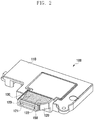
- FIG. 2 is a perspective view illustrating an external appearance of a speaker module according to a first exemplary embodiment of the present invention.
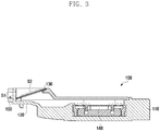
- FIG. 3 is a cross-sectional view illustrating a speaker module according to the first exemplary embodiment of the present invention.
- a speaker module 100 includes a body 110, a duct 120, a protection member 130, a speaker 140, and a soundproof member 150.
- the speaker 140 is mounted within the body 110, and a sound signal output from the speaker 140 may be radiated to the outside through a passage formed with the body 110 and the duct 120. That is, a sound signal output from the speaker 140 may be radiated to the outside through an opening surface of the duct 120.
- the duct 120 according to the first exemplary embodiment of the present invention includes a first opening surface 121, a second opening surface 122, and a third opening surface 123.
- the first opening surface 121 is formed in various forms (e.g., a stepwise form) such as a vertical form or a form inclined with respect to a length (extending) direction of the duct 120.
- the second opening surface 122 is formed at one side end (e.g. inside) of the duct 120.
- the third opening surface 123 is formed to expose the second opening surface 122.
- the second opening surface 122 is formed to have an area larger than that of a cross-sectional opening surface formed vertically with respect to a length direction of the duct 120 and be disposed inclinedly with respect to each of the first opening surface 121 and the second opening surface 123 so as to guide the sound signal to the first opening surface 121 and the third opening surface 123.
- the second opening surface 122 is formed inclindedly with respect to the extending direction of the duct 120.
- the first opening surface 121 is in contact with a wall of a hole (not shown, hereinafter, a speaker hole) formed in a case of a mobile device (not shown). That is, a sound signal output from the speaker 140 is radiated to the outside of a mobile device (not shown) through a speaker hole.
- the soundproof member 150 for preventing leakage of a sound signal is positioned between the speaker hole and the first opening surface 121.
- the soundproof member 150 may be formed of various appropriate materials such as sponge, poron, and rubber.
- the second opening surface 122 is a surface to which a protection member 130 for preventing a foreign substance from entering the speaker module is attached, and it is preferable that an area S2 of the second opening surface 122 be larger than an area S1 of the first opening surface 121.
- the protection member 130 may be formed with mesh and non-woven cloth.
- An audio signal passes through the protection member 130 with low sound signal transfer resistance.
- a plurality of holes i.e., net knot
- the third opening surface 123 is formed to easily attach the protection member 130 to the second opening surface 122.
- the speaker module 100 can reduce sound pressure deterioration due to the protection member 130, compared with the speaker module 10 of the related art. This is because an area of an opening surface to which the protection member 130 is attached is large compared with a case of the relate art and thus as a sound signal is radiated through a wide area, the transfer resistance to a sound signal passing through the protection member 130 is relatively small.
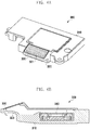
- FIG. 4 is a perspective view illustrating an external appearance of a speaker module according to a second exemplary embodiment of the present invention.
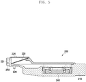
- FIG. 5 is a cross-sectional view illustrating a speaker module according to the second exemplary embodiment of the present invention.
- a speaker module 200 according to the second exemplary embodiment of the present invention includes a body 210, a duct 220, a protection member 230, a speaker 240, and a soundproof member 250.
- the speaker module 200 according to the second exemplary embodiment of the present invention is similar to the speaker module 100 according to the first exemplary embodiment.
- the speaker module 200 according to the second exemplary embodiment of the present invention includes a soundproof cover 224 fastened to the third opening surface 223.
- the soundproof cover 224 prevents a sound signal from being distributed and output to a third opening surface 223. That is, the speaker module 200 according to the second exemplary embodiment of the present invention prevents performance deterioration of a sound signal occurring as the sound signal is distributed and output to the first opening surface 221 and the third opening surface 223.
- a soundproof cover 224 is formed separately, but the present invention is not limited thereto.
- the soundproof cover 224 may be integrally formed with another part which is one of constituent elements of the speaker module 200.
- the third opening surface 223 may be soundproof-processed by body of the mobile device.
- the body of the mobile device may include a constituent element (e.g., a bracket) for blocking the third opening surface 223.
- a soundproof member e.g., poron and sponge
- a soundproof process may be performed.
- one protection member is attached to the second opening surfaces 122 and 222, but the present invention is not limited thereto. That is, in another exemplary embodiment of the present invention, one or more protection members may be attached to the speaker modules 100 and 200.
- a protection member may be further attached to the first opening surfaces 121 and 221 of the speaker modules 100 and 200.
- the protection member attached to the first opening surfaces 121 and 221 may be more sparsely spaced than, i.e., may have a hole size larger than, a protection member attached to the second opening surfaces 122 and 222.
- a protection member attached to the first opening surface 121 or 221 and the second opening surface 122 or 222 may have the same hole size.
- FIGs. 6A and 6B are a perspective view and a cross-sectional view illustrating an external appearance and a section of a speaker module according to a third exemplary embodiment of the present invention.
- a speaker module 300 includes a speaker 340 for outputting a sound signal, a body 310 in which the speaker 340 is mounted, a duct 320 for forming a radiation path of a sound signal output from the speaker 340, and a protection member 330 attached to an opening surface 321 of the duct 320.
- the speaker module 300 according to the third exemplary embodiment of the present invention has an opening surface 321, unlike the speaker modules 100 and 200 according to the first exemplary embodiment and the second exemplary embodiment.
- the opening surface 321 is not formed vertically with respect to a length direction of the duct 320. This is to enable the opening surface 321 to have an area larger than that of a cross-sectional opening surface formed vertically with respect to a length direction of the duct 320.
- the opening surface 321 of the duct 320 may be formed to have a tilt angle, essentially any angle except for '90°' and '270°', which are angles having a minimum sectional area, and '180°' and '360°', which are angles parallel to a length direction of the duct 320.
- the speaker module 300 according to the third exemplary embodiment of the present invention has one opening surface, unlike the speaker modules 100 and 200 according to the first exemplary embodiment and the second exemplary embodiment respectively, and thus the protection member 330 is more easily attached.
- the speaker module 300 is fastened to the body of the mobile device.
- a sound signal of the speaker module 300 is radiated to the outside through a speaker hole formed in a side surface of the body of the mobile device.
- the opening surface 321 has a tilt
- the opening surface 321 and the body of the mobile device do not fully contact each other, and a gap may be formed between the opening surface 321 and the body of the mobile device. Due to the gap, all sound signals are not output to the outside through a speaker hole, and some sound signal may be leaked.
- the body of the mobile device includes a duct structure (not shown, hereinafter, a second duct) coupled to the duct 320 (hereinafter, a first duct) of the speaker module 300. That is, as a second duct coupled to the first duct 320 is provided in the body of the mobile device, a sound signal output from the speaker module 300 may be radiated to the outside without leakage. In this way, when the second duct is formed in the body of the mobile device, the protection member 330 may be attached to an opening surface of the second duct. The opening surface of the second duct is opposite to the opening surface of the first duct 320.
- one side end of the duct 320 to which the protection member 330 is attached is formed as a tilt with respect to the extending direction of the duct 320, but one side end of the duct 320 of the speaker module 300 may be formed in various forms having a surface larger than an opening surface of the speaker apparatus 10 of the related art.
- one side end of the duct 320 of the speaker module 300 may be formed in a protruded form while having a tilt such as ' ⁇ ' and '>' or in a protruded form while having a curvature such as '(' and ')'.
- one side end of the duct 320 to which the protection member 330 is attached in a stepwise form, an area to which the protection member 330 is attached may be increased.
- One side end structure of the duct 320 may be applied to the foregoing first and second exemplary embodiments of the present invention for forming the second opening surface, and to the fourth exemplary embodiment through a fifth exemplary embodiment to be described later.
- FIGs. 7A and 7B are a perspective view and a cross-sectional view illustrating an external appearance and a section of a speaker module according to a fourth exemplary embodiment of the present invention.
- a speaker module 400 includes a speaker 440 for outputting a sound signal, a body 410 in which the speaker 440 is mounted, a duct 420 for forming a radiation path of a sound signal output through the speaker 440, and a protection member 430 attached to the duct 420 to prevent a foreign substance from entering the speaker module.
- the duct 420 includes a first opening surface 421 vertically formed at one side of the duct 420, and a second opening surface 422 formed parallel to a length direction of the duct 420.
- the protection member 430 is attached to enclose the first opening surface 421 and the second opening surface 422.
- the speaker module 400 according to the fourth exemplary embodiment of the present invention has one or more opening surfaces, and as the protection member 430 is attached to the one or more opening surfaces, a sound performance (sound pressure) is prevented from being deteriorated by the protection member 430. That is, the speaker module 400 according to the fourth exemplary embodiment of the present invention does not attach a protection member to one opening surface having a narrow area like the related art but instead forms one or more opening surfaces, and thus a protection member may be attached to a relatively wide area compared to the related art, thereby minimizing deterioration of a sound performance due to the protection member.
- the speaker module 400 is fastened to the body of the mobile device.
- a sound signal of the speaker 440 is radiated to the outside of the speaker module 400 through the first opening surface 421 and the second opening surface 422 of the duct 420, and is radiated to the outside through a speaker hole formed at one side (e.g., a side surface) of the body of the mobile device.
- a sound signal is radiated through only the first opening surface 421, and thus the same problem as that of the related art occurs.
- the body of the mobile device be formed so as to not block the second opening surface 422 of the speaker module 400.
- the body of the mobile device may include a device (e.g., a duct, a gap) for transferring a sound signal output through the second opening surface 422 to the speaker hole.
- a device e.g., a duct, a gap
- an upper end area of a soundproof member 450 is removed. This is to prevent a problem that a sound signal radiated through the second opening surface 422 is not transferred to the outside through the speaker hole of the case by the soundproof member 450.
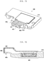
- FIGs. 8A and 8B are a perspective view and a cross-sectional view illustrating an external appearance and a section of a speaker module according to a fifth exemplary embodiment of the present invention.
- a speaker module 500 includes a body 510, a duct 520, a protection member 530, a speaker 540, and a soundproof member 550.
- the speaker module 500 according to the fifth exemplary embodiment of the present invention has a structure similar to that of the speaker modules 100 and 200 according to the first exemplary embodiment and the second exemplary embodiment, respectively.
- the speaker module 500 according to the fifth exemplary embodiment of the present invention includes a soundproof cover 524 fastened to an opening surface above protection member 530.
- the soundproof cover 524 prevents a sound signal from being distributed and output to the opening surface above protection member 530.
- the protection member 530 is attached in different forms than in the previous embodiments.
- the protection members 130 and 230 have a vertical tilt
- the protection member 530 of the speaker module 500 according to the fifth exemplary embodiment has a tilt in a horizontal direction, as shown in FIGs. 8A and 8B .
- the speaker module 500 includes one protection member 530, but the present invention is not limited thereto. That is, as described above, the speaker module 500 may include a plurality of protection members.
- FIG. 9 is a cross-sectional view illustrating a fastened shape of a speaker module and a mobile device having a duct radiation structure according to an exemplary embodiment of the present invention.
- a mobile device 700 includes a body 710 in which a speaker module 600 is mounted and a second duct 720 formed in the body 710 for radiating a sound signal of the speaker module 600 to the outside.
- the mobile device 700 according to an exemplary embodiment of the present invention includes a protection member 730 for preventing a foreign substance from entering the inside of the second duct 720.
- the second duct 720 includes a first opening surface contacting with a first duct 620, a second opening surface formed within the second duct 720 and to which the protection member 730 is attached, and a third opening surface positioned at an opposite side of the first opening surface for radiating a sound signal to the outside.
- the mobile device 700 includes a soundproof member 650 positioned between the first opening surface of the second duct 720 and an opening surface of the first duct 620 for transferring a sound signal output from a speaker 640 without leakage from the first duct 620 to the second duct 720.
- the mobile device 700 may include a plurality of protection members.
- the mobile device 700 may further attach a protection member 750 to the third opening surface.
- the protection member 750 attached to the third opening surface may have a hole size greater than or equal to the protection member 730 attached to the inside of the second duct 720.
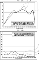
- FIGs. 10A and 10B are graphs illustrating a sound performance measurement result of a speaker module of the related art and speaker modules of exemplary embodiments of the present invention.
- FIG. 10A is a graph illustrating a sound pressure measurement result of each speaker module
- FIG. 10B is a graph illustrating a Total Harmonic Distortion (THD) measurement result of each speaker module.
- THD Total Harmonic Distortion
- a first graph A is a sound pressure graph of the speaker module 10 of the related art
- a second graph B is a sound pressure graph of the speaker module 100 according to the first exemplary embodiment of the present invention
- a third graph C is a sound pressure graph of the speaker module 200 according to the second exemplary embodiment of the present invention.
- the speaker modules 100 and 200 according to exemplary embodiments of the present invention are similar in a frequency band, or a sound pressure of about 1 decibel (dB) to 6 dB is increased, compared with the speaker module 10 of the related art.
- a sound pressure of the speaker module 200 according to the second exemplary embodiment is further increased in an intermediate and large band, from about 900 Hertz (Hz) to about 3000 Hz and again from about 4500 Hz to about 7500 Hz, compared with the speaker module 100 according to the first exemplary embodiment.
- a fourth graph A' is a THD graph of the speaker module 10 of the related art
- a fifth graph B' is a THD graph of the speaker module 100 according to the first exemplary embodiment of the present invention
- a sixth graph C' is a THD graph of the speaker module 200 according to the second exemplary embodiment of the present invention.
- the speaker modules 100 and 200 according to exemplary embodiments of the present invention are generally lower in THD than the speaker module 10 of the related art.
- a level of a harmonic component included in a signal output from the speaker modules 100 and 200 according to exemplary embodiments of the present invention is low. That is, it can be seen that a performance of the speaker modules 100 and 200 according to exemplary embodiments of the present invention is improved, compared with the speaker module 10 of the related art.
- FIGs. 10A and 10B illustrate measurement results of the speaker modules 100 and 200 according to only the first exemplary embodiment and the second exemplary embodiment of the present invention.
- a performance of the speaker modules 300, 400, and 500 according to the third, fourth, and fifth exemplary embodiments of the present invention, and the speaker module 600 fastened to a mobile device having a duct radiation structure described in FIG. 9 is similarly improved in comparison to the speaker module 10 of the related art.
- a protection member is attached to a duct formed in a speaker module or a mobile device body.
- a protection member may be doubly attached. That is, in an exemplary embodiment of the present invention, a protection member may be attached to a duct and a speaker hole of a body of a mobile device. In this case, it is preferable to attach a protection member in which a size of a hole is relatively large to the speaker hole and the duct.
- a protection member may be doubly attached to a first opening surface and a second opening surface.
- a speaker module for a mobile device and a mobile device having a duct radiation structure can increase an area of an opening surface to which a protection member is attached by changing a shape of a duct in which a sound signal is radiated. In this way, as an area of the opening surface is increased, a sound performance deterioration problem by the protection member can be improved. That is, a sound performance of the speaker module can be improved.
Landscapes
- Physics & Mathematics (AREA)
- Engineering & Computer Science (AREA)
- Acoustics & Sound (AREA)
- Signal Processing (AREA)
- Health & Medical Sciences (AREA)
- Otolaryngology (AREA)
- Telephone Set Structure (AREA)
- Details Of Audible-Bandwidth Transducers (AREA)
- Obtaining Desirable Characteristics In Audible-Bandwidth Transducers (AREA)
Claims (6)
- Dispositif mobile comprenant : un module de haut-parleur (300) ;
un corps auquel le module de haut-parleur (300) est fixé ; et
un élément de protection (330) ;
ledit module de haut-parleur (300) comprenant :un haut-parleur (340) conçu pour délivrer en sortie un signal sonore ;un corps de module de haut-parleur (310) auquel le haut-parleur (340) est monté ; etun conduit (320) définissant une surface d'ouverture (321) pour rayonner un signal sonore délivré en sortie depuis le haut-parleur (340) jusqu'à l'extérieur du module de haut-parleur (300), ledit conduit (320) étant conçu pour guider un signal sonore délivré en sortie depuis le haut-parleur (340) jusqu'à la surface d'ouverture (321) du conduit (320), ladite surface d'ouverture (321) étant inclinée par rapport à une direction d'extension du conduit (320) ; ledit corps du dispositif mobile comprenant une structure de raccordement possédant une surface d'ouverture conçue pour correspondre à la surface d'ouverture (321) du conduit (320) afin de rayonner un signal sonore délivré en sortie depuis le module de haut-parleur (300) jusqu'à l'extérieur du dispositif mobile sans fuite ; etledit élément de protection (330) étant disposé entre la surface d'ouverture (321) du conduit (320) et la surface d'ouverture de la structure de raccordement pour empêcher une substance étrangère d'entrer à l'intérieur du module de haut-parleur (300). - Dispositif mobile selon la revendication 1, ladite structure de raccordement comprenant un second conduit.
- Dispositif mobile selon la revendication 1, ledit élément de protection (330) possédant une superficie plus grande que la superficie de la section transversale du conduit (320) dans un plan perpendiculaire à la direction de la longueur du conduit (320).
- Dispositif mobile selon l'une quelconque des revendications précédentes, ledit élément de protection (330) étant formé d'une maille ou d'un tissu non-tissé.
- Dispositif mobile selon l'une quelconque des revendications précédentes, ledit élément de protection étant attaché à la surface d'ouverture (321) du conduit (320).
- Dispositif mobile selon l'une quelconque des revendications 1 à 4, ledit élément de protection étant attaché à la surface d'ouverture de la structure de raccordement.
Priority Applications (2)
| Application Number | Priority Date | Filing Date | Title |
|---|---|---|---|
| EP18203487.6A EP3496415B1 (fr) | 2012-02-24 | 2013-02-25 | Module de haut-parleur pour dispositif mobile et dispositif mobile ayant une structure de rayonnement de conduite |
| EP20169331.4A EP3748987A1 (fr) | 2012-02-24 | 2013-02-25 | Module de haut-parleur pour dispositif mobile et dispositif mobile ayant une structure de rayonnement de conduite |
Applications Claiming Priority (2)
| Application Number | Priority Date | Filing Date | Title |
|---|---|---|---|
| KR1020120019346A KR101991504B1 (ko) | 2012-02-24 | 2012-02-24 | 휴대 기기용 스피커 모듈 및 덕트 방사 구조를 구비하는 휴대 기기 |
| EP13156525.1A EP2632172B1 (fr) | 2012-02-24 | 2013-02-25 | Module de haut-parleur pour dispositif mobile et dispositif mobile ayant une structure de rayonnement de conduit |
Related Parent Applications (2)
| Application Number | Title | Priority Date | Filing Date |
|---|---|---|---|
| EP13156525.1A Division-Into EP2632172B1 (fr) | 2012-02-24 | 2013-02-25 | Module de haut-parleur pour dispositif mobile et dispositif mobile ayant une structure de rayonnement de conduit |
| EP13156525.1A Division EP2632172B1 (fr) | 2012-02-24 | 2013-02-25 | Module de haut-parleur pour dispositif mobile et dispositif mobile ayant une structure de rayonnement de conduit |
Related Child Applications (2)
| Application Number | Title | Priority Date | Filing Date |
|---|---|---|---|
| EP20169331.4A Division EP3748987A1 (fr) | 2012-02-24 | 2013-02-25 | Module de haut-parleur pour dispositif mobile et dispositif mobile ayant une structure de rayonnement de conduite |
| EP18203487.6A Division EP3496415B1 (fr) | 2012-02-24 | 2013-02-25 | Module de haut-parleur pour dispositif mobile et dispositif mobile ayant une structure de rayonnement de conduite |
Publications (2)
| Publication Number | Publication Date |
|---|---|
| EP2945397A1 EP2945397A1 (fr) | 2015-11-18 |
| EP2945397B1 true EP2945397B1 (fr) | 2018-10-31 |
Family
ID=47790009
Family Applications (4)
| Application Number | Title | Priority Date | Filing Date |
|---|---|---|---|
| EP13156525.1A Active EP2632172B1 (fr) | 2012-02-24 | 2013-02-25 | Module de haut-parleur pour dispositif mobile et dispositif mobile ayant une structure de rayonnement de conduit |
| EP15174495.0A Active EP2945397B1 (fr) | 2012-02-24 | 2013-02-25 | Module de haut-parleur pour dispositif mobile et dispositif mobile ayant une structure de rayonnement de conduite |
| EP18203487.6A Active EP3496415B1 (fr) | 2012-02-24 | 2013-02-25 | Module de haut-parleur pour dispositif mobile et dispositif mobile ayant une structure de rayonnement de conduite |
| EP20169331.4A Ceased EP3748987A1 (fr) | 2012-02-24 | 2013-02-25 | Module de haut-parleur pour dispositif mobile et dispositif mobile ayant une structure de rayonnement de conduite |
Family Applications Before (1)
| Application Number | Title | Priority Date | Filing Date |
|---|---|---|---|
| EP13156525.1A Active EP2632172B1 (fr) | 2012-02-24 | 2013-02-25 | Module de haut-parleur pour dispositif mobile et dispositif mobile ayant une structure de rayonnement de conduit |
Family Applications After (2)
| Application Number | Title | Priority Date | Filing Date |
|---|---|---|---|
| EP18203487.6A Active EP3496415B1 (fr) | 2012-02-24 | 2013-02-25 | Module de haut-parleur pour dispositif mobile et dispositif mobile ayant une structure de rayonnement de conduite |
| EP20169331.4A Ceased EP3748987A1 (fr) | 2012-02-24 | 2013-02-25 | Module de haut-parleur pour dispositif mobile et dispositif mobile ayant une structure de rayonnement de conduite |
Country Status (5)
| Country | Link |
|---|---|
| US (3) | US9479850B2 (fr) |
| EP (4) | EP2632172B1 (fr) |
| KR (1) | KR101991504B1 (fr) |
| CN (3) | CN107027084B (fr) |
| ES (1) | ES2793276T3 (fr) |
Families Citing this family (30)
| Publication number | Priority date | Publication date | Assignee | Title |
|---|---|---|---|---|
| KR101991504B1 (ko) | 2012-02-24 | 2019-09-30 | 삼성전자주식회사 | 휴대 기기용 스피커 모듈 및 덕트 방사 구조를 구비하는 휴대 기기 |
| US9307314B2 (en) | 2013-06-12 | 2016-04-05 | Samsung Electronics Co., Ltd. | Electronic device with side acoustic emission type speaker device |
| CN103747398B (zh) * | 2013-12-25 | 2017-05-17 | 歌尔股份有限公司 | 扬声器模组及其包含该扬声器模组的电子装置 |
| CN104168528B (zh) * | 2014-09-01 | 2018-09-18 | 歌尔股份有限公司 | 扬声器模组 |
| CN105376680B (zh) * | 2015-11-16 | 2018-09-21 | 青岛海信移动通信技术股份有限公司 | 一种移动终端 |
| KR102409316B1 (ko) * | 2016-02-19 | 2022-06-16 | 삼성전자 주식회사 | 측면 방사형 스피커 장치를 구비하는 전자 장치 |
| CN105592389B (zh) * | 2016-02-29 | 2019-02-26 | 歌尔股份有限公司 | 扬声器模组 |
| CN206181361U (zh) * | 2016-10-25 | 2017-05-17 | 瑞声声学科技(深圳)有限公司 | 扬声器箱 |
| US10567868B2 (en) * | 2017-01-26 | 2020-02-18 | AAC Technologies Pte. Ltd. | Sound generator |
| TWI689209B (zh) * | 2017-03-14 | 2020-03-21 | 大陸商廣東歐珀移動通信有限公司 | 揚聲器、揚聲裝置及行動終端 |
| CN107547974B (zh) * | 2017-07-04 | 2019-10-22 | 瑞声科技(新加坡)有限公司 | 扬声器箱 |
| CN108174338A (zh) * | 2017-12-21 | 2018-06-15 | 瑞声科技(新加坡)有限公司 | 扬声器箱及其装配方法 |
| CN107909968B (zh) * | 2017-12-28 | 2019-07-23 | 武汉华星光电半导体显示技术有限公司 | Amoled显示面板的驱动方法及相关产品 |
| KR102533426B1 (ko) | 2018-05-03 | 2023-05-17 | 삼성전자 주식회사 | 전자장치의 관로 구조 및 이를 포함하는 전자장치 |
| EP3820123B1 (fr) * | 2018-07-16 | 2023-06-28 | Guangdong Oppo Mobile Telecommunications Corp., Ltd. | Ensemble boîtier, et dispositif électronique |
| CN109618251B (zh) * | 2018-10-24 | 2024-07-19 | 通力电梯有限公司 | 具有增加声压级别的结构和具有该结构的声音指示器 |
| KR102573519B1 (ko) * | 2018-12-04 | 2023-09-04 | 삼성전자주식회사 | 스피커 모듈을 포함하는 전자 장치 |
| JP7092153B2 (ja) * | 2019-03-13 | 2022-06-28 | 株式会社デンソーエレクトロニクス | 発音器およびその製造方法 |
| WO2021000110A1 (fr) * | 2019-06-29 | 2021-01-07 | 瑞声声学科技(深圳)有限公司 | Structure de sortie de son destinée à un équipement électronique |
| KR102651992B1 (ko) * | 2019-07-02 | 2024-03-27 | 삼성전자주식회사 | 음향 모듈을 포함하는 전자 장치 |
| CN113329303A (zh) * | 2020-02-28 | 2021-08-31 | 博思特国际股份有限公司 | 发声体 |
| US10972832B1 (en) * | 2020-03-09 | 2021-04-06 | Chih-chi Chen | Sounding body |
| CN213938240U (zh) * | 2020-11-30 | 2021-08-10 | 瑞声科技(新加坡)有限公司 | 一种扬声器箱及移动终端 |
| EP4198682A4 (fr) | 2020-12-31 | 2024-03-06 | Samsung Electronics Co., Ltd. | Dispositif électronique comprenant un haut-parleur |
| KR102867953B1 (ko) * | 2021-01-12 | 2025-10-10 | 삼성전자주식회사 | 소리가 전파되는 관로 구조를 포함하는 전자 장치 |
| EP4344247A4 (fr) | 2021-06-28 | 2024-10-16 | Samsung Electronics Co., Ltd. | Dispositif électronique comprenant une structure de résonance |
| KR102880838B1 (ko) * | 2021-06-28 | 2025-11-04 | 삼성전자주식회사 | 공명 구조를 포함하는 전자 장치 |
| CN215453258U (zh) * | 2021-06-30 | 2022-01-07 | 瑞声光电科技(常州)有限公司 | 扬声器箱 |
| US11962960B2 (en) * | 2021-07-19 | 2024-04-16 | Samsung Electronics Co., Ltd. | Electronic device including sound component assembly |
| JP2023176238A (ja) * | 2022-05-31 | 2023-12-13 | Tdk株式会社 | 音響デバイス |
Family Cites Families (22)
| Publication number | Priority date | Publication date | Assignee | Title |
|---|---|---|---|---|
| US5909490A (en) * | 1997-07-07 | 1999-06-01 | Hughes Electronics Corporation | Omnidirectional audio in a communications device |
| US6002949A (en) * | 1997-11-18 | 1999-12-14 | Nortel Networks Corporation | Handset with a single transducer for handset and handsfree functionality |
| KR200257575Y1 (ko) * | 1998-12-18 | 2002-08-22 | 엘지정보통신주식회사 | 단말기의스피커소리유도장치 |
| DE60202397T2 (de) | 2001-05-08 | 2005-06-16 | Matsushita Electric Industrial Co., Ltd., Kadoma | Lautsprecher und Mobilendgerät |
| TWI267315B (en) * | 2002-07-01 | 2006-11-21 | Sony Ericsson Mobile Comm Ab | Communication terminal |
| DE60234327D1 (de) | 2002-07-01 | 2009-12-24 | Sony Ericsson Mobile Comm Ab | Lautsprecheranordnung für Kommunikationsendgerät |
| US6758303B2 (en) * | 2002-10-31 | 2004-07-06 | Motorola, Inc. | Electronic device having a multi-mode acoustic system and method for radiating sound waves |
| US6785395B1 (en) * | 2003-06-02 | 2004-08-31 | Motorola, Inc. | Speaker configuration for a portable electronic device |
| JP4002561B2 (ja) * | 2004-06-30 | 2007-11-07 | 埼玉日本電気株式会社 | 携帯型電子機器における小型スピーカ実装構造及び該構造を備えた携帯型電子機器 |
| KR20060004523A (ko) * | 2004-07-09 | 2006-01-12 | 엘지전자 주식회사 | 음질 개선장치를 구비한 휴대용 단말기 |
| JP2006191213A (ja) * | 2004-12-28 | 2006-07-20 | Citizen Electronics Co Ltd | 電気音響変換器及び携帯端末装置 |
| JP2006279260A (ja) | 2005-03-28 | 2006-10-12 | Nec Saitama Ltd | 携帯端末 |
| KR200408511Y1 (ko) * | 2005-11-24 | 2006-02-13 | 부전전자부품 주식회사 | 이동통신 단말기용 스피커 |
| JP4853029B2 (ja) * | 2006-01-20 | 2012-01-11 | 日本電気株式会社 | 携帯端末、スピーカ、及び携帯端末のスピーカ取付構造 |
| JP2007215075A (ja) | 2006-02-13 | 2007-08-23 | Hosiden Corp | 電気音響変換装置 |
| JP4793047B2 (ja) * | 2006-03-23 | 2011-10-12 | ソニー株式会社 | 電気光学装置および電子機器 |
| US20070223744A1 (en) * | 2006-03-23 | 2007-09-27 | Epson Imaging Devices Corporation | Electro-optic device and electronic apparatus |
| US8126138B2 (en) * | 2007-01-05 | 2012-02-28 | Apple Inc. | Integrated speaker assembly for personal media device |
| US8055003B2 (en) | 2008-04-01 | 2011-11-08 | Apple Inc. | Acoustic systems for electronic devices |
| US8213659B2 (en) * | 2009-06-30 | 2012-07-03 | Nokia Corporation | Apparatus with adjustable speaker arrangement |
| KR101612791B1 (ko) * | 2010-02-04 | 2016-04-18 | 엘지전자 주식회사 | 스피커 모듈 및 이를 갖는 휴대 단말기 |
| KR101991504B1 (ko) * | 2012-02-24 | 2019-09-30 | 삼성전자주식회사 | 휴대 기기용 스피커 모듈 및 덕트 방사 구조를 구비하는 휴대 기기 |
-
2012
- 2012-02-24 KR KR1020120019346A patent/KR101991504B1/ko active Active
-
2013
- 2013-02-19 US US13/770,628 patent/US9479850B2/en active Active
- 2013-02-25 CN CN201710334216.5A patent/CN107027084B/zh active Active
- 2013-02-25 ES ES18203487T patent/ES2793276T3/es active Active
- 2013-02-25 CN CN201711179294.9A patent/CN107948851B/zh active Active
- 2013-02-25 EP EP13156525.1A patent/EP2632172B1/fr active Active
- 2013-02-25 EP EP15174495.0A patent/EP2945397B1/fr active Active
- 2013-02-25 EP EP18203487.6A patent/EP3496415B1/fr active Active
- 2013-02-25 EP EP20169331.4A patent/EP3748987A1/fr not_active Ceased
- 2013-02-25 CN CN201310059042.8A patent/CN103327432B/zh active Active
-
2016
- 2016-09-22 US US15/273,282 patent/US10433050B2/en active Active
-
2019
- 2019-08-22 US US16/548,227 patent/US10993020B2/en active Active
Non-Patent Citations (1)
| Title |
|---|
| None * |
Also Published As
| Publication number | Publication date |
|---|---|
| KR101991504B1 (ko) | 2019-09-30 |
| US20170013351A1 (en) | 2017-01-12 |
| US10433050B2 (en) | 2019-10-01 |
| EP3496415B1 (fr) | 2020-04-29 |
| CN107027084B (zh) | 2020-09-11 |
| CN107948851A (zh) | 2018-04-20 |
| ES2793276T3 (es) | 2020-11-13 |
| EP2632172B1 (fr) | 2015-08-12 |
| US20190379966A1 (en) | 2019-12-12 |
| US9479850B2 (en) | 2016-10-25 |
| US10993020B2 (en) | 2021-04-27 |
| EP2945397A1 (fr) | 2015-11-18 |
| KR20130097590A (ko) | 2013-09-03 |
| EP3496415A1 (fr) | 2019-06-12 |
| EP2632172A1 (fr) | 2013-08-28 |
| EP3748987A1 (fr) | 2020-12-09 |
| CN107027084A (zh) | 2017-08-08 |
| US20130223655A1 (en) | 2013-08-29 |
| CN107948851B (zh) | 2020-02-18 |
| CN103327432B (zh) | 2017-12-22 |
| CN103327432A (zh) | 2013-09-25 |
Similar Documents
| Publication | Publication Date | Title |
|---|---|---|
| EP2945397B1 (fr) | Module de haut-parleur pour dispositif mobile et dispositif mobile ayant une structure de rayonnement de conduite | |
| US8767992B2 (en) | Mobile media device case/attachment for providing passive acoustic boosting | |
| CN103024613B (zh) | 具有扬声器声音放大路径的保护罩 | |
| US9247348B2 (en) | Speaker having a horizontal former | |
| US8428291B2 (en) | Speaker system with subwoofer | |
| WO2021197114A1 (fr) | Dispositif électronique | |
| CN108650345A (zh) | 移动终端 | |
| KR20140145068A (ko) | 측면 방사형 스피커 장치를 구비하는 전자 장치 | |
| US8116504B2 (en) | Electronic device having a receiver | |
| KR102210118B1 (ko) | 휴대 기기용 스피커 모듈 및 덕트 방사 구조를 구비하는 휴대 기기 | |
| US8208977B2 (en) | Mobile terminal and speaker device thereof | |
| US20240305918A1 (en) | Electroacoustic module and electronic device | |
| CN111107212B (zh) | 防尘组件及电子设备 | |
| US10231041B2 (en) | Loudspeaker module | |
| US20250310672A1 (en) | Sound-producing apparatus and electronic device | |
| CN114866913B (zh) | 发声模组和终端设备 | |
| US8922586B2 (en) | Electronic device with reduced form factor | |
| KR20110073191A (ko) | 지향성 스피커 모듈 및 이를 포함하는 휴대 단말기 |
Legal Events
| Date | Code | Title | Description |
|---|---|---|---|
| PUAI | Public reference made under article 153(3) epc to a published international application that has entered the european phase |
Free format text: ORIGINAL CODE: 0009012 |
|
| AC | Divisional application: reference to earlier application |
Ref document number: 2632172 Country of ref document: EP Kind code of ref document: P |
|
| AK | Designated contracting states |
Kind code of ref document: A1 Designated state(s): AL AT BE BG CH CY CZ DE DK EE ES FI FR GB GR HR HU IE IS IT LI LT LU LV MC MK MT NL NO PL PT RO RS SE SI SK SM TR |
|
| 17P | Request for examination filed |
Effective date: 20160510 |
|
| RBV | Designated contracting states (corrected) |
Designated state(s): AL AT BE BG CH CY CZ DE DK EE ES FI FR GB GR HR HU IE IS IT LI LT LU LV MC MK MT NL NO PL PT RO RS SE SI SK SM TR |
|
| STAA | Information on the status of an ep patent application or granted ep patent |
Free format text: STATUS: EXAMINATION IS IN PROGRESS |
|
| 17Q | First examination report despatched |
Effective date: 20161206 |
|
| GRAP | Despatch of communication of intention to grant a patent |
Free format text: ORIGINAL CODE: EPIDOSNIGR1 |
|
| STAA | Information on the status of an ep patent application or granted ep patent |
Free format text: STATUS: GRANT OF PATENT IS INTENDED |
|
| RIC1 | Information provided on ipc code assigned before grant |
Ipc: H04R 1/00 20060101ALI20180413BHEP Ipc: H04R 1/34 20060101ALI20180413BHEP Ipc: H04M 1/03 20060101ALI20180413BHEP Ipc: H04R 1/02 20060101AFI20180413BHEP Ipc: H04R 1/28 20060101ALI20180413BHEP Ipc: H04R 1/08 20060101ALI20180413BHEP |
|
| INTG | Intention to grant announced |
Effective date: 20180504 |
|
| GRAS | Grant fee paid |
Free format text: ORIGINAL CODE: EPIDOSNIGR3 |
|
| GRAJ | Information related to disapproval of communication of intention to grant by the applicant or resumption of examination proceedings by the epo deleted |
Free format text: ORIGINAL CODE: EPIDOSDIGR1 |
|
| GRAL | Information related to payment of fee for publishing/printing deleted |
Free format text: ORIGINAL CODE: EPIDOSDIGR3 |
|
| STAA | Information on the status of an ep patent application or granted ep patent |
Free format text: STATUS: EXAMINATION IS IN PROGRESS |
|
| GRAR | Information related to intention to grant a patent recorded |
Free format text: ORIGINAL CODE: EPIDOSNIGR71 |
|
| STAA | Information on the status of an ep patent application or granted ep patent |
Free format text: STATUS: GRANT OF PATENT IS INTENDED |
|
| INTC | Intention to grant announced (deleted) | ||
| GRAA | (expected) grant |
Free format text: ORIGINAL CODE: 0009210 |
|
| STAA | Information on the status of an ep patent application or granted ep patent |
Free format text: STATUS: THE PATENT HAS BEEN GRANTED |
|
| INTG | Intention to grant announced |
Effective date: 20180919 |
|
| AC | Divisional application: reference to earlier application |
Ref document number: 2632172 Country of ref document: EP Kind code of ref document: P |
|
| AK | Designated contracting states |
Kind code of ref document: B1 Designated state(s): AL AT BE BG CH CY CZ DE DK EE ES FI FR GB GR HR HU IE IS IT LI LT LU LV MC MK MT NL NO PL PT RO RS SE SI SK SM TR |
|
| REG | Reference to a national code |
Ref country code: CH Ref legal event code: EP Ref country code: GB Ref legal event code: FG4D |
|
| REG | Reference to a national code |
Ref country code: AT Ref legal event code: REF Ref document number: 1060828 Country of ref document: AT Kind code of ref document: T Effective date: 20181115 |
|
| REG | Reference to a national code |
Ref country code: IE Ref legal event code: FG4D |
|
| REG | Reference to a national code |
Ref country code: DE Ref legal event code: R096 Ref document number: 602013046167 Country of ref document: DE |
|
| REG | Reference to a national code |
Ref country code: NL Ref legal event code: FP |
|
| REG | Reference to a national code |
Ref country code: LT Ref legal event code: MG4D |
|
| REG | Reference to a national code |
Ref country code: AT Ref legal event code: MK05 Ref document number: 1060828 Country of ref document: AT Kind code of ref document: T Effective date: 20181031 |
|
| PG25 | Lapsed in a contracting state [announced via postgrant information from national office to epo] |
Ref country code: FI Free format text: LAPSE BECAUSE OF FAILURE TO SUBMIT A TRANSLATION OF THE DESCRIPTION OR TO PAY THE FEE WITHIN THE PRESCRIBED TIME-LIMIT Effective date: 20181031 Ref country code: NO Free format text: LAPSE BECAUSE OF FAILURE TO SUBMIT A TRANSLATION OF THE DESCRIPTION OR TO PAY THE FEE WITHIN THE PRESCRIBED TIME-LIMIT Effective date: 20190131 Ref country code: HR Free format text: LAPSE BECAUSE OF FAILURE TO SUBMIT A TRANSLATION OF THE DESCRIPTION OR TO PAY THE FEE WITHIN THE PRESCRIBED TIME-LIMIT Effective date: 20181031 Ref country code: LT Free format text: LAPSE BECAUSE OF FAILURE TO SUBMIT A TRANSLATION OF THE DESCRIPTION OR TO PAY THE FEE WITHIN THE PRESCRIBED TIME-LIMIT Effective date: 20181031 Ref country code: PL Free format text: LAPSE BECAUSE OF FAILURE TO SUBMIT A TRANSLATION OF THE DESCRIPTION OR TO PAY THE FEE WITHIN THE PRESCRIBED TIME-LIMIT Effective date: 20181031 Ref country code: BG Free format text: LAPSE BECAUSE OF FAILURE TO SUBMIT A TRANSLATION OF THE DESCRIPTION OR TO PAY THE FEE WITHIN THE PRESCRIBED TIME-LIMIT Effective date: 20190131 Ref country code: ES Free format text: LAPSE BECAUSE OF FAILURE TO SUBMIT A TRANSLATION OF THE DESCRIPTION OR TO PAY THE FEE WITHIN THE PRESCRIBED TIME-LIMIT Effective date: 20181031 Ref country code: LV Free format text: LAPSE BECAUSE OF FAILURE TO SUBMIT A TRANSLATION OF THE DESCRIPTION OR TO PAY THE FEE WITHIN THE PRESCRIBED TIME-LIMIT Effective date: 20181031 Ref country code: AT Free format text: LAPSE BECAUSE OF FAILURE TO SUBMIT A TRANSLATION OF THE DESCRIPTION OR TO PAY THE FEE WITHIN THE PRESCRIBED TIME-LIMIT Effective date: 20181031 Ref country code: IS Free format text: LAPSE BECAUSE OF FAILURE TO SUBMIT A TRANSLATION OF THE DESCRIPTION OR TO PAY THE FEE WITHIN THE PRESCRIBED TIME-LIMIT Effective date: 20190228 |
|
| PG25 | Lapsed in a contracting state [announced via postgrant information from national office to epo] |
Ref country code: AL Free format text: LAPSE BECAUSE OF FAILURE TO SUBMIT A TRANSLATION OF THE DESCRIPTION OR TO PAY THE FEE WITHIN THE PRESCRIBED TIME-LIMIT Effective date: 20181031 Ref country code: PT Free format text: LAPSE BECAUSE OF FAILURE TO SUBMIT A TRANSLATION OF THE DESCRIPTION OR TO PAY THE FEE WITHIN THE PRESCRIBED TIME-LIMIT Effective date: 20190301 Ref country code: RS Free format text: LAPSE BECAUSE OF FAILURE TO SUBMIT A TRANSLATION OF THE DESCRIPTION OR TO PAY THE FEE WITHIN THE PRESCRIBED TIME-LIMIT Effective date: 20181031 Ref country code: GR Free format text: LAPSE BECAUSE OF FAILURE TO SUBMIT A TRANSLATION OF THE DESCRIPTION OR TO PAY THE FEE WITHIN THE PRESCRIBED TIME-LIMIT Effective date: 20190201 Ref country code: SE Free format text: LAPSE BECAUSE OF FAILURE TO SUBMIT A TRANSLATION OF THE DESCRIPTION OR TO PAY THE FEE WITHIN THE PRESCRIBED TIME-LIMIT Effective date: 20181031 |
|
| PG25 | Lapsed in a contracting state [announced via postgrant information from national office to epo] |
Ref country code: CZ Free format text: LAPSE BECAUSE OF FAILURE TO SUBMIT A TRANSLATION OF THE DESCRIPTION OR TO PAY THE FEE WITHIN THE PRESCRIBED TIME-LIMIT Effective date: 20181031 Ref country code: DK Free format text: LAPSE BECAUSE OF FAILURE TO SUBMIT A TRANSLATION OF THE DESCRIPTION OR TO PAY THE FEE WITHIN THE PRESCRIBED TIME-LIMIT Effective date: 20181031 Ref country code: IT Free format text: LAPSE BECAUSE OF FAILURE TO SUBMIT A TRANSLATION OF THE DESCRIPTION OR TO PAY THE FEE WITHIN THE PRESCRIBED TIME-LIMIT Effective date: 20181031 |
|
| REG | Reference to a national code |
Ref country code: DE Ref legal event code: R097 Ref document number: 602013046167 Country of ref document: DE |
|
| PG25 | Lapsed in a contracting state [announced via postgrant information from national office to epo] |
Ref country code: RO Free format text: LAPSE BECAUSE OF FAILURE TO SUBMIT A TRANSLATION OF THE DESCRIPTION OR TO PAY THE FEE WITHIN THE PRESCRIBED TIME-LIMIT Effective date: 20181031 Ref country code: SK Free format text: LAPSE BECAUSE OF FAILURE TO SUBMIT A TRANSLATION OF THE DESCRIPTION OR TO PAY THE FEE WITHIN THE PRESCRIBED TIME-LIMIT Effective date: 20181031 Ref country code: EE Free format text: LAPSE BECAUSE OF FAILURE TO SUBMIT A TRANSLATION OF THE DESCRIPTION OR TO PAY THE FEE WITHIN THE PRESCRIBED TIME-LIMIT Effective date: 20181031 Ref country code: SM Free format text: LAPSE BECAUSE OF FAILURE TO SUBMIT A TRANSLATION OF THE DESCRIPTION OR TO PAY THE FEE WITHIN THE PRESCRIBED TIME-LIMIT Effective date: 20181031 |
|
| PLBE | No opposition filed within time limit |
Free format text: ORIGINAL CODE: 0009261 |
|
| STAA | Information on the status of an ep patent application or granted ep patent |
Free format text: STATUS: NO OPPOSITION FILED WITHIN TIME LIMIT |
|
| REG | Reference to a national code |
Ref country code: CH Ref legal event code: PL |
|
| 26N | No opposition filed |
Effective date: 20190801 |
|
| PG25 | Lapsed in a contracting state [announced via postgrant information from national office to epo] |
Ref country code: LU Free format text: LAPSE BECAUSE OF NON-PAYMENT OF DUE FEES Effective date: 20190225 Ref country code: SI Free format text: LAPSE BECAUSE OF FAILURE TO SUBMIT A TRANSLATION OF THE DESCRIPTION OR TO PAY THE FEE WITHIN THE PRESCRIBED TIME-LIMIT Effective date: 20181031 Ref country code: MC Free format text: LAPSE BECAUSE OF FAILURE TO SUBMIT A TRANSLATION OF THE DESCRIPTION OR TO PAY THE FEE WITHIN THE PRESCRIBED TIME-LIMIT Effective date: 20181031 |
|
| REG | Reference to a national code |
Ref country code: BE Ref legal event code: MM Effective date: 20190228 |
|
| REG | Reference to a national code |
Ref country code: IE Ref legal event code: MM4A |
|
| PG25 | Lapsed in a contracting state [announced via postgrant information from national office to epo] |
Ref country code: CH Free format text: LAPSE BECAUSE OF NON-PAYMENT OF DUE FEES Effective date: 20190228 Ref country code: LI Free format text: LAPSE BECAUSE OF NON-PAYMENT OF DUE FEES Effective date: 20190228 |
|
| PG25 | Lapsed in a contracting state [announced via postgrant information from national office to epo] |
Ref country code: IE Free format text: LAPSE BECAUSE OF NON-PAYMENT OF DUE FEES Effective date: 20190225 |
|
| PG25 | Lapsed in a contracting state [announced via postgrant information from national office to epo] |
Ref country code: BE Free format text: LAPSE BECAUSE OF NON-PAYMENT OF DUE FEES Effective date: 20190228 Ref country code: FR Free format text: LAPSE BECAUSE OF NON-PAYMENT OF DUE FEES Effective date: 20190228 |
|
| PG25 | Lapsed in a contracting state [announced via postgrant information from national office to epo] |
Ref country code: TR Free format text: LAPSE BECAUSE OF FAILURE TO SUBMIT A TRANSLATION OF THE DESCRIPTION OR TO PAY THE FEE WITHIN THE PRESCRIBED TIME-LIMIT Effective date: 20181031 |
|
| PG25 | Lapsed in a contracting state [announced via postgrant information from national office to epo] |
Ref country code: MT Free format text: LAPSE BECAUSE OF NON-PAYMENT OF DUE FEES Effective date: 20190225 |
|
| PG25 | Lapsed in a contracting state [announced via postgrant information from national office to epo] |
Ref country code: CY Free format text: LAPSE BECAUSE OF FAILURE TO SUBMIT A TRANSLATION OF THE DESCRIPTION OR TO PAY THE FEE WITHIN THE PRESCRIBED TIME-LIMIT Effective date: 20181031 |
|
| PG25 | Lapsed in a contracting state [announced via postgrant information from national office to epo] |
Ref country code: HU Free format text: LAPSE BECAUSE OF FAILURE TO SUBMIT A TRANSLATION OF THE DESCRIPTION OR TO PAY THE FEE WITHIN THE PRESCRIBED TIME-LIMIT; INVALID AB INITIO Effective date: 20130225 |
|
| PG25 | Lapsed in a contracting state [announced via postgrant information from national office to epo] |
Ref country code: MK Free format text: LAPSE BECAUSE OF FAILURE TO SUBMIT A TRANSLATION OF THE DESCRIPTION OR TO PAY THE FEE WITHIN THE PRESCRIBED TIME-LIMIT Effective date: 20181031 |
|
| PGFP | Annual fee paid to national office [announced via postgrant information from national office to epo] |
Ref country code: NL Payment date: 20250121 Year of fee payment: 13 |
|
| PGFP | Annual fee paid to national office [announced via postgrant information from national office to epo] |
Ref country code: DE Payment date: 20250120 Year of fee payment: 13 |
|
| PGFP | Annual fee paid to national office [announced via postgrant information from national office to epo] |
Ref country code: GB Payment date: 20250120 Year of fee payment: 13 |