EP2945224A1 - Flachbandabgriff - Google Patents
Flachbandabgriff Download PDFInfo
- Publication number
- EP2945224A1 EP2945224A1 EP15167443.9A EP15167443A EP2945224A1 EP 2945224 A1 EP2945224 A1 EP 2945224A1 EP 15167443 A EP15167443 A EP 15167443A EP 2945224 A1 EP2945224 A1 EP 2945224A1
- Authority
- EP
- European Patent Office
- Prior art keywords
- contact
- screw
- tap
- ribbon cable
- flat tape
- Prior art date
- Legal status (The legal status is an assumption and is not a legal conclusion. Google has not performed a legal analysis and makes no representation as to the accuracy of the status listed.)
- Granted
Links
Images




Classifications
-
- H—ELECTRICITY
- H01—ELECTRIC ELEMENTS
- H01R—ELECTRICALLY-CONDUCTIVE CONNECTIONS; STRUCTURAL ASSOCIATIONS OF A PLURALITY OF MUTUALLY-INSULATED ELECTRICAL CONNECTING ELEMENTS; COUPLING DEVICES; CURRENT COLLECTORS
- H01R4/00—Electrically-conductive connections between two or more conductive members in direct contact, i.e. touching one another; Means for effecting or maintaining such contact; Electrically-conductive connections having two or more spaced connecting locations for conductors and using contact members penetrating insulation
- H01R4/24—Connections using contact members penetrating or cutting insulation or cable strands
- H01R4/2404—Connections using contact members penetrating or cutting insulation or cable strands the contact members having teeth, prongs, pins or needles penetrating the insulation
-
- H—ELECTRICITY
- H01—ELECTRIC ELEMENTS
- H01R—ELECTRICALLY-CONDUCTIVE CONNECTIONS; STRUCTURAL ASSOCIATIONS OF A PLURALITY OF MUTUALLY-INSULATED ELECTRICAL CONNECTING ELEMENTS; COUPLING DEVICES; CURRENT COLLECTORS
- H01R12/00—Structural associations of a plurality of mutually-insulated electrical connecting elements, specially adapted for printed circuits, e.g. printed circuit boards [PCB], flat or ribbon cables, or like generally planar structures, e.g. terminal strips, terminal blocks; Coupling devices specially adapted for printed circuits, flat or ribbon cables, or like generally planar structures; Terminals specially adapted for contact with, or insertion into, printed circuits, flat or ribbon cables, or like generally planar structures
- H01R12/50—Fixed connections
- H01R12/59—Fixed connections for flexible printed circuits, flat or ribbon cables or like structures
- H01R12/65—Fixed connections for flexible printed circuits, flat or ribbon cables or like structures characterised by the terminal
- H01R12/67—Fixed connections for flexible printed circuits, flat or ribbon cables or like structures characterised by the terminal insulation penetrating terminals
-
- H—ELECTRICITY
- H01—ELECTRIC ELEMENTS
- H01R—ELECTRICALLY-CONDUCTIVE CONNECTIONS; STRUCTURAL ASSOCIATIONS OF A PLURALITY OF MUTUALLY-INSULATED ELECTRICAL CONNECTING ELEMENTS; COUPLING DEVICES; CURRENT COLLECTORS
- H01R4/00—Electrically-conductive connections between two or more conductive members in direct contact, i.e. touching one another; Means for effecting or maintaining such contact; Electrically-conductive connections having two or more spaced connecting locations for conductors and using contact members penetrating insulation
- H01R4/24—Connections using contact members penetrating or cutting insulation or cable strands
- H01R4/2416—Connections using contact members penetrating or cutting insulation or cable strands the contact members having insulation-cutting edges, e.g. of tuning fork type
- H01R4/242—Connections using contact members penetrating or cutting insulation or cable strands the contact members having insulation-cutting edges, e.g. of tuning fork type the contact members being plates having a single slot
- H01R4/2425—Flat plates, e.g. multi-layered flat plates
- H01R4/2429—Flat plates, e.g. multi-layered flat plates mounted in an insulating base
- H01R4/2433—Flat plates, e.g. multi-layered flat plates mounted in an insulating base one part of the base being movable to push the cable into the slot
-
- H—ELECTRICITY
- H01—ELECTRIC ELEMENTS
- H01R—ELECTRICALLY-CONDUCTIVE CONNECTIONS; STRUCTURAL ASSOCIATIONS OF A PLURALITY OF MUTUALLY-INSULATED ELECTRICAL CONNECTING ELEMENTS; COUPLING DEVICES; CURRENT COLLECTORS
- H01R9/00—Structural associations of a plurality of mutually-insulated electrical connecting elements, e.g. terminal strips or terminal blocks; Terminals or binding posts mounted upon a base or in a case; Bases therefor
- H01R9/03—Connectors arranged to contact a plurality of the conductors of a multiconductor cable, e.g. tapping connections
- H01R9/031—Connectors arranged to contact a plurality of the conductors of a multiconductor cable, e.g. tapping connections for multiphase cables, e.g. with contact members penetrating insulation of a plurality of conductors
-
- H—ELECTRICITY
- H01—ELECTRIC ELEMENTS
- H01R—ELECTRICALLY-CONDUCTIVE CONNECTIONS; STRUCTURAL ASSOCIATIONS OF A PLURALITY OF MUTUALLY-INSULATED ELECTRICAL CONNECTING ELEMENTS; COUPLING DEVICES; CURRENT COLLECTORS
- H01R12/00—Structural associations of a plurality of mutually-insulated electrical connecting elements, specially adapted for printed circuits, e.g. printed circuit boards [PCB], flat or ribbon cables, or like generally planar structures, e.g. terminal strips, terminal blocks; Coupling devices specially adapted for printed circuits, flat or ribbon cables, or like generally planar structures; Terminals specially adapted for contact with, or insertion into, printed circuits, flat or ribbon cables, or like generally planar structures
- H01R12/50—Fixed connections
- H01R12/59—Fixed connections for flexible printed circuits, flat or ribbon cables or like structures
- H01R12/65—Fixed connections for flexible printed circuits, flat or ribbon cables or like structures characterised by the terminal
- H01R12/67—Fixed connections for flexible printed circuits, flat or ribbon cables or like structures characterised by the terminal insulation penetrating terminals
- H01R12/675—Fixed connections for flexible printed circuits, flat or ribbon cables or like structures characterised by the terminal insulation penetrating terminals with contacts having at least a slotted plate for penetration of cable insulation, e.g. insulation displacement contacts for round conductor flat cables
-
- H—ELECTRICITY
- H01—ELECTRIC ELEMENTS
- H01R—ELECTRICALLY-CONDUCTIVE CONNECTIONS; STRUCTURAL ASSOCIATIONS OF A PLURALITY OF MUTUALLY-INSULATED ELECTRICAL CONNECTING ELEMENTS; COUPLING DEVICES; CURRENT COLLECTORS
- H01R4/00—Electrically-conductive connections between two or more conductive members in direct contact, i.e. touching one another; Means for effecting or maintaining such contact; Electrically-conductive connections having two or more spaced connecting locations for conductors and using contact members penetrating insulation
- H01R4/24—Connections using contact members penetrating or cutting insulation or cable strands
- H01R4/2416—Connections using contact members penetrating or cutting insulation or cable strands the contact members having insulation-cutting edges, e.g. of tuning fork type
- H01R4/242—Connections using contact members penetrating or cutting insulation or cable strands the contact members having insulation-cutting edges, e.g. of tuning fork type the contact members being plates having a single slot
-
- H—ELECTRICITY
- H01—ELECTRIC ELEMENTS
- H01R—ELECTRICALLY-CONDUCTIVE CONNECTIONS; STRUCTURAL ASSOCIATIONS OF A PLURALITY OF MUTUALLY-INSULATED ELECTRICAL CONNECTING ELEMENTS; COUPLING DEVICES; CURRENT COLLECTORS
- H01R4/00—Electrically-conductive connections between two or more conductive members in direct contact, i.e. touching one another; Means for effecting or maintaining such contact; Electrically-conductive connections having two or more spaced connecting locations for conductors and using contact members penetrating insulation
- H01R4/24—Connections using contact members penetrating or cutting insulation or cable strands
- H01R4/2475—Connections using contact members penetrating or cutting insulation or cable strands the contact members penetrating the insulation being actuated by screws, nuts or bolts
- H01R4/2483—Connections using contact members penetrating or cutting insulation or cable strands the contact members penetrating the insulation being actuated by screws, nuts or bolts penetrating the area under the screw tip
Definitions
- the present invention relates to a tap for a ribbon cable, which in turn has a plurality of parallel-running wires.
- the parallel cores are surrounded by an insulating jacket.
- Such ribbon cables make it possible to be contacted at any point to tap the electrical potential of one or more wires at a desired location.
- Such flat tape taps usually consist of a housing comprising the ribbon cable.
- the ribbon cable is passed through the housing and extends in the horizontal direction.
- displaceable connection contacts are arranged in the vertical direction. The connection contacts are thus traversable at right angles to the ribbon cable. If the connection contacts are moved in the direction of the wires of the ribbon cable, they sever the insulating jacket of the ribbon cable at the respective contact points and form a contact with the wire.
- Such a housing with so-called insulation displacement contacts is known.
- the contacts are fork-shaped.
- the two forks have facing cutting edges. The cutting edges sever when contacting the insulating jacket of the ribbon cable and clamp the wire to be contacted between them.
- connection contacts are designed as piercing screws.
- connection contacts are present for each wire of the ribbon cable.
- the invention is based on the object, a Flachbandabgriff so make sure that only the number of connection contacts corresponding to the number of taps required is present.
- the invention is based on the basic idea to provide an actuating element which is movable back and forth between the individual contact points.
- the control element is in each case a contact point for contacting freely and at the same time inactivates the other contact points.
- the actuating element can serve as a drive element for a connection contact and thus switch the connection contact between different contact points back and forth in order to contact them selectively.
- the adjusting element is designed as a longitudinally displaceable carriage.
- the longitudinally displaceable carriage can be moved either at right angles, ie at an angle of 90 ° to the central longitudinal direction of the cable cores. This running at right angles to the wires displacement direction of the carriage allows a particularly space-saving design of Flachbandabgriffs.
- the carriage is diagonally displaceable to the ribbon cable.
- the displacement direction of the carriage thus runs at a 45 ° angle or at another angle obliquely to the central longitudinal direction of the wires of the ribbon cable.
- This diagonal direction of displacement of the carriage has the advantage of increased air and creepage distances, so that the ribbon tap is also suitable for higher electrical potentials.
- the diagonal shift direction must therefore not run exactly at an angle of 45 ° to the central longitudinal direction of the wires. Rather, an oblique course in an angular range of 85 ° to 10 °, preferably in the range of 30 ° to 60 ° meant.
- the adjusting element is designed as a perforated disc.
- This perforated disk has a through hole aligned with the respective contact point. The through hole can be moved by means of the perforated disc to each contact point, wherein the not provided with the through hole areas of the perforated disc cover the other contact points.
- the perforated disc is rotatably drivable with a rotary switch.
- connection contacts For example, it is possible to use as terminal contacts per se known fork-shaped insulation displacement contacts with mutually facing cutting edges.
- the insulation displacement contacts are driven in an advantageous development of a pivot lever to move from its inactive position into its active position to be pivoted.
- a tool attack on the pivot lever may be formed, for example, a pocket for a screwdriver blade.
- pivot lever and the insulation displacement contact is mounted in a separate contact housing.
- the contact housing with the built-in pivot lever and it mounted insulation displacement contact then forms an assembly that can be easily inserted into a corresponding receptacle at the contact point. It is also possible to insert this module in the movable carriage so as to be able to move the insulation displacement contact between the individual contact points back and forth.
- a known piercing screw as a connection contact.
- the piercing screw is guided longitudinally movable in a hollow cylindrical screw-in channel or screw-in funnel.
- the piercing screw is surrounded by a spacer sleeve like a wreath.
- the spacer sleeve is guided along its outer surfaces on the inner surfaces of the screw-in or Einschraubtrichters moved longitudinally while the screw head of the piercing screw is rotatably mounted in the spacer sleeve.
- the spacer sleeve has a double function as a captive securing the piercing screw in Einschraubkanal or screw-in funnel.
- the spacer sleeve also has a colored design, it serves as an indicator of the position of the piercing screw. If the spacer sleeve is visible at the open end of the screw-in channel or screw-in funnel, the piercing screw is in its inactive position. However, if the sleeve is no longer visible, the piercing screw is screwed deep into the screw-in channel or screw-in funnel and is therefore in your contact position. In the contact position pierces the screw tip of the piercing screw the insulating jacket of the ribbon cable and rests on the wire to be contacted.
- the spacer sleeve is pushed onto the screw head of the piercing screw or latched.
- it is considered advantageous on the spacer sleeve three at a 60 ° angle provide spaced fishing hooks. Two of these fishing hooks are preferably rigid and a third fishing hook is resilient. When snapping the spacer sleeve, the spring-loaded fishing hook springs out, thus allowing the screw head of the piercing screw to slide over.
- Torx a star-shaped tool attack in the screw head of the piercing screw with rounded tips and corners. Screws with such star-shaped tool attacks are marketed under the name "Torx" in the trade. These Torx screws have plug-compatible screwdriver bits for manual, cordless or torque screwdrivers. Due to the larger outer diameter of the spacer sleeve compared with the head diameter of the screw head of the piercing screw, it is possible to increase the inner diameter of the screw-in channel or screw-in funnel as well. In this enlarged Einschraubkanäle or screw funnel then a tool with a screwdriver bit can easily dive and be used to attach the piercing screw, which is montageetechnisch advantageous.
- a further development of the invention relates to the design of the longitudinally displaceable carriage.
- the screw-in or screw-in funnel is held in a U-shaped retaining clip and forms the longitudinally displaceable carriage.
- the U-legs of the retaining clip thereby form the bracket side walls.
- the screw-in funnel or screw-in channel is held and guided between the side walls and can be pushed back and forth along the side walls.
- locking grooves are formed in the upper edges of the clamp side walls formed by the U-legs. The locking grooves are each formed at those positions at which contact points are present. In this way, the screw-in channel or screw-in between the different contact points defined to be moved back and forth and locked above the corresponding contact each secure.
- latching feet are integrally formed on the lower edges of the side walls of the clamp facing away from the upper edges of the clamp side walls. aid the locking feet, the retaining clip on Flachbandabgriff be locked in corresponding openings.
- the unit of retaining clip and screw-in channel or screw-in funnel again forms a snap-on to the ribbon tap or the housing of Flachbandabgriffs module.
- the ribbon tap can have a preferably pivotably mounted housing cover which completely covers the displaceable slide or the perforated disk in the closed state and thus prevents any manipulation at the contact point.
- the housing cover may have a transparent area acting as a sight glass. Through this transparent area, the respective functional position of the carriage can be determined, so that the contact assignment is recognizable.
- the respective potential designation can be printed on the outside of the lid, so that the contact assignment can be seen even more easily from the outside. It is particularly advantageous to make the housing cover suitable both for the carriage variant and also for the perforated disc variants.
- the housing cover has a perpendicular to the central longitudinal direction of the wires or diagonal to the central longitudinal direction of the wires running dome.
- Fig. 1 the housing of the flat tape tap 1 and the ribbon cable 2 passing through the housing can be seen.
- Fig. 1 is further apparent the effective as a slide screw-in funnel 3 and the screw-in funnel 3 superimposed U-shaped retaining clip 4.
- the wires 6 are embedded in the insulating jacket 7 of the ribbon cable second
- Fig. 1 a shows the ribbon tap 1 with a pivotally mounted housing cover 28, which completely covers the displaceable screw-in funnel 3 in the closed state and thus prevents any manipulation at the contact point.
- the housing cover 28 has a transparent oblong hole 29 acting as a sight glass. Through this transparent slot 29, the respective functional position of the screw-in funnel 3 is visible, so that the contact assignment is recognizable. Outside on the housing cover 28, the respective potential designation 30 is printed, so that the pin assignment can be easily read from the outside.
- the housing cover 28 has an upwardly projecting, compared to the other areas of the housing cover 28 gradually increasing raised lid portion 31.
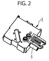
- Fig. 2 shows the housing of Flachbandabgriffs 1 with disassembled retaining clip 4 and dismantled screw funnel 3.
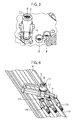
- Fig. 3 recognizable is the screw-in funnel 3 with the screw head 8 a piercing screw 11.
- the screw heads 8 of the piercing screws 11 for the neutral conductor and the protective conductor contact can be seen.
- Fig. 4 It can be seen that the screw-in funnel 3 with the piercing screw 11 along the contact bracket 9 of the socket contact 10 is diagonal to the wires 6 slidably.
- the piercing screws 11 of the protective conductor and the neutral conductor are screwed directly into the corresponding socket contacts 10.
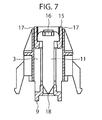
- Fig. 7 is in the sectional view again the spacer sleeve 15 recognizable, which is pushed onto the piercing screw 11.
- the piercing screw 11 is guided with the outer surface 17 of the spacer sleeve 15 in the screw-in funnel 3.
- the screw tip 18 is also good, which pierces the insulating jacket 7 of the ribbon cable 2 and rests in the contacting position on the wire 6.
- the spacer sleeve 15 which secures the one hand, the piercing screw 11 captive in the screw 3 and which on the other hand serves as an indicator.
- the spacer sleeve 15 is clearly visible from the outside, thus signaling the inactive position of the piercing screw 11. If the piercing screw 11, however, completely screwed, the spacer sleeve 15 is no longer visible.
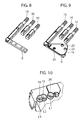
- socket contacts 10 of a second embodiment of the flat strip tap 1 according to the invention are recognizable.
- two socket contacts 10 act as contact elements for the neutral conductor or the protective conductor.
- the socket contact 10 with the molded contact bracket 9 is in turn provided for tapping the electrical potential.
- a perforated disc 19 is pivotally mounted with through holes 20.
- the through holes 20 are aligned in each case with the contact point to be released.
- there the contact point L1 from Through hole 20 is released, whereas the two adjacent contacts L2 and L3 are each closed by the perforated disc 19.
- FIG. 11 and FIG. 12 again show the open from the through hole 20 contact and an adjacent rotary switch 21, which is effective as a drive element for the perforated disc 19. From the representation of Fig. 12 Finally, it can be seen that the rotary switch 21 between the potentials L1, L2 and L3 for activating or deactivating the corresponding terminal contact back and forth is movable.
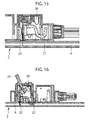
- Fig. 13 shows the perpendicular to the wires 6 of the ribbon cable 2 slidable carriage 22.
- the carriage 22 takes on a fork-like insulation displacement contact 23.
- the fork-like insulation displacement contact 23 in turn has two mutually facing cutting edges 24 on its forks. With the cutting edges 24 of the insulation displacement contact 23 cuts through the insulating jacket 7 of the ribbon cable 2 and contacted by clamping the sheath 7 coated by the insulating sheath 6 of the ribbon cable. 2
- FIG. 14 and Fig. 16 a screwdriver blade 25 can be seen, which engages in a tool attack on the pivot lever 26.
- the pivot lever 26 of the insulation displacement contact 23 By means of the pivot lever 26 of the insulation displacement contact 23 from his in Fig. 15 shown inactive position in his in Fig. 16 shown contact position in the direction of the wire 6 of the ribbon cable 2 pressed down.
- the derivation of the electrical potential takes place in accordance with the embodiment Fig. 13, Fig. 14 .
- FIGS. 15 and 16 via a copper wire 27, which is conductively connected to the insulation displacement contact 23.
- the through hole 20 is assigned by means of the rotary switch 21 to the desired contact L1, L2 or L3. Subsequently, a piercing screw initially not located on the ribbon tap is screwed into a thread located below the through-hole 20.
- the piercing screw 11 in this case pierces the insulating jacket 7 of the ribbon cable 2 and rests on its associated core 6 for contacting.
Landscapes
- Multi-Conductor Connections (AREA)
- Connections By Means Of Piercing Elements, Nuts, Or Screws (AREA)
Abstract
Description
- Die vorliegende Erfindung betrifft einen Abgriff für ein Flachbandkabel, welches seinerseits mehrere parallel laufende Adern aufweist. Die parallel laufenden Aderns sind von einem Isoliermantel umgeben. Derartige Flachbandkabel ermöglichen es, an beliebigen Stellen kontaktiert zu werden, um das elektrische Potential einer oder mehrerer Adern an einer gewünschten Stelle abzugreifen. Derartige Flachbandabgriffe bestehen in der Regel aus einem das Flachbandkabel umfassenden Gehäuse. Dabei ist das Flachbandkabel durch das Gehäuse durchgeleitet und erstreckt sich in horizontalter Richtung. Im Gehäuse sind in vertikaler Richtung verschiebbare Anschlusskontakte angeordnet. Die Anschlusskontakte sind also rechtwinklig zum Flachbandkabel verfahrbar. Werden die Anschlusskontakte in Richtung auf die Adern des Flachbandkabels verfahren, durchtrennen sie den Isoliermantel des Flachbandkabels an den jeweiligen Kontaktstellen und bilden mit der Ader einen Berührungskontakt aus.
- Aus der
EP 16 24 528 ist ein derartiges Gehäuse mit sogenannten Schneidklemmkontakten bekannt. Bei den Schneidklemmkontakten sind die Kontakte gabelförmig ausgebildet. Die beiden Gabelzinken weisen einander zugewandte Schneidkanten auf. Die Schneidkanten durchtrennen beim Kontaktieren den Isoliermantel des Flachbandkabels und klemmen die zu kontaktierenden Ader zwischen sich. - Aus der
EP 23 15 217 ist ebenfalls ein Flachbandabgriff mit einem Gehäuse bekannt. Dort sind die Anschlusskontakte als Piercingschrauben ausgebildet. - Nachteilig beim bekannten Stand der Technik ist die Tatsache, dass für jede Ader des Flachbandkabels Anschlusskontakte vorhanden sind. Häufig ist es nämlich erwünscht, nur wenige Adern des Flachbandkabels zu kontaktieren. Hiervon ausgehend liegt der Erfindung die Aufgabe zugrunde, einen Flachbandabgriff so zu gestalten, dass nur die der Anzahl der benötigten Abgriffe entsprechende Anzahl von Anschlusskontakten vorhanden ist.
- Diese Aufgabe ist durch die Merkmalskombination des Patentanspruchs 1 in erfinderischer Weise gelöst. Die Unteransprüche lehren teilweise vorteilhafte und teilweise für sich selbst erfinderische Weiterbildungen dieser Erfindung.
- Die Erfindung beruht auf der Grundüberlegung, ein Stellelement vorzusehen, welches zwischen den einzelnen Kontaktstellen hin- und her bewegbar ist. Das Stellelement gibt dabei jeweils eine Kontaktstelle zur Kontaktierung frei und inaktiviert zugleich die übrigen Kontaktstellen. Das Stellelement kann in diesem Zusammenhang als Antriebselement für einen Anschlusskontakt dienen und so den Anschlusskontakt zwischen verschiedenen Kontaktstellen hin- und her schalten, um diese wahlweise zu kontaktieren.
- Mit der Erfindung ist es beispielsweise möglich, bei einem fünfadrigen Flachbandkabel den Schutzleiter und den Nullleiter fest zu kontaktieren und das elektrische Potential wahlweise von den Leitern L1 oder L2 oder L3 abzuzweigen. In der Regel sind sämtliche Kontaktstellen des Flachleitungsabgriffs mit Stecker- oder Buchsenkontakten von Steckverbindern mechanisch verbunden, so dass das Potential aus den Adern des Flachbandkabels in die entsprechenden Kontakte des Steckverbinders eingeleitet wird. Bezogen auf einen 3-poligen elektrischen Steckverbinder kann beispielsweise der rechte und der mittlere Anschlusskontakt fest dem Nullleiter bzw. dem Schutzleiter zugeordnet sein, während der verbleibende linke Anschlusskontakt wahlweise mit den Potentialen L1, L2 oder L3 elektrisch verbunden werden kann.
- Natürlich ist es auch möglich, andere als 3- oder 5-polige Flachbandkabel bzw. Flachleitungsabgriffe mit der Erfindung zu versehen. Die vorerwähnten Ausführungen sind insoweit nicht beschränkend, sondern nur beispielhaft.
- Mit der Erfindung ist es sogar möglich, eine einmal gewählte Kontaktbelegung wieder zu verändern. Es wird einfach das jeweilige Kontaktelement von der fehlerhaften Kontaktstelle entfernt und durch das Stellelement an die korrekte Kontaktstelle verfahren. Es ist deshalb grundsätzlich möglich, eine Ader auch mehrfach zu piercen, ohne dass dies zu einem Ausfall der Anlage führt.
- In einer ersten Ausgestaltung ist das Stellelement als längsverschieblicher Schlitten ausgestaltet. Der längsverschiebliche Schlitten kann entweder rechtwinklig, also in einem Winkel von 90° zur Mittellängsrichtung der Leitungsadern verschoben werden. Diese rechtwinklig zu den Adern verlaufende Verschieberichtung des Schlittens ermöglicht eine besonders platzsparende Ausgestaltung des Flachbandabgriffs.
- In weiterer Ausgestaltung ist der Schlitten diagonal zum Flachbandkabel verschiebbar. Die Verschieberichtung des Schlittens läuft also in einem 45°-Winkel oder in einem anderen Winkel schräg zur Mittellängsrichtung der Adern des Flachbandkabels. Diese diagonale Verschieberichtung des Schlittens hat den Vorteil von vergrößerten Luft- und Kriechstrecken, so dass der Flachbandabgriff auch für höhere elektrische Potentiale geeignet ist. Die diagonale Verschieberichtung muß also nicht exakt in einem Winkel von 45° zur Mittellängsrichtung der Adern verlaufen. Vielmehr ist ein schräger Verlauf in einem Winkelbereich von 85° bis 10°, vorzugsweise im Bereich von 30° bis 60° gemeint.
- In einer weiteren Ausgestaltung ist das Stellelement als Lochscheibe ausgestaltet. Diese Lochscheibe weist ein mit der jeweiligen Kontaktstelle fluchtendes Durchgangsloch auf. Das Durchgangsloch kann mithilfe der Lochscheibe zu jeder Kontaktstelle hin bewegt werden, wobei die nicht mit dem Durchgangsloch versehenen Bereiche der Lochscheibe die übrigen Kontaktstellen abdecken. In vorteilhafter Ausgestaltung ist die Lochscheibe mit einem Drehschalter drehantreibbar.
- Weitere Varianten der Erfindung betreffen die Ausgestaltung der Anschlusskontakte. So ist es beispielsweise möglich, als Anschlusskontakte an sich bekannte gabelförmige Schneidklemmkontakte mit einander zugewandten Schneidkanten zu verwenden. Die Schneidklemmkontakte sind in vorteilhafter Weiterbildung von einem Schwenkhebel angetrieben, um aus ihrer Inaktivstellung in ihre Aktivstellung verschwenkt zu werden. Hierfür kann ein Werkzeugangriff am Schwenkhebel ausgebildet sein, beispielsweise eine Tasche für eine Schrauberklinge.
- In einer bevorzugten Variante ist der Schwenkhebel und der Schneidklemmkontakt in einem separaten Kontaktgehäuse gelagert. Das Kontaktgehäuse mit dem eingebauten Schwenkhebel und daran gelagertem Schneidklemmkontakt bildet dann eine Baugruppe, die einfach in eine entsprechende Aufnahme an der Kontaktstelle eingeschoben werden kann. Auch ist es möglich, diese Baugruppe in den bewegbaren Schlitten einzuschieben, um so den Schneidklemmkontakt zwischen den einzelnen Kontaktstellen hin- und her verschieben zu können.
- Eine weitere Ausführungsform betrifft eine an sich bekannte Piercingschraube als Anschlusskontakt. In vorteilhafter Ausgestaltung ist die Piercingschraube in einem hohlzylindrischen Einschraubkanal oder Einschraubtrichter längs verfahrbar geführt. In einer für sich selbst gesehen erfinderischen Variante ist die Piercingschraube von einer Distanzhülse kranzartig umschlossen. Die Distanzhülse ist dabei mit ihren Außenflächen an den Innenflächen des Einschraubkanals oder Einschraubtrichters längs verfahrbar geführt, während der Schraubenkopf der Piercingschraube in der Distanzhülse drehbeweglich gelagert ist. Die Distanzhülse hat eine Doppelfunktion zum einem als Verliersicherung der Piercingschraube im Einschraubkanal oder Einschraubtrichter. Ist die Distanzhülse darüber hinaus farbig ausgestaltet, dient sie zum anderen als Indikator für die jeweilige Stellung der Piercingschraube. Ist die Distanzhülse am offenen Ende des Einschraubkanals oder Einschraubtrichters sichtbar, befindet sich die Piercingschraube in ihrer Inaktivstellung. Ist die Hülse hingegen nicht mehr sichtbar, ist die Piercingschraube tief in den Einschraubkanal oder Einschraubtrichter eingeschraubt und befindet sich somit in Ihrer Kontaktstellung. In der Kontaktstellung durchstößt die Schraubenspitze der Piercingschraube den Isoliermantel des Flachbandkabels und liegt auf der zu kontaktierenden Ader auf.
- In vorteilhafter Ausgestaltung ist die Distanzhülse auf den Schraubenkopf der Piercingschraube aufschiebbar oder aufrastbar. Bei der aufrastbaren Variante wird es als vorteilhaft angesehen, an der Distanzhülse drei in einem 60°-Winkel voneinander beabstandete Fanghaken vorzusehen. Zwei dieser Fanghaken sind vorzugsweise starr und ein dritter Fanghaken ist federelastisch. Beim Aufrasten der Distanzhülse federt der federelastische Fanghaken aus und ermöglicht so das Übergleiten des Schraubenkopfs der Piercingschraube.
- Besonders vorteilhaft ist die Kombination der Distanzhülse mit einem sternförmigen Werkzeugangriff im Schraubenkopf der Piercingsschraube mit abgerundeten Spitzen und Ecken. Schrauben mit derartigen sternförmigen Werkzeugangriffen werden unter der Kennzeichnung "Torx" im Handel vertrieben. Zu diesen Torxschrauben existieren steckkompatible Schrauberbits für Hand-, Akku- oder Drehmomentschrauber. Aufgrund des verglichen mit dem Kopfdurchmesser des Schraubenkopfs der Piercingschraube größeren Außendurchmessers der Distanzhülse ist es möglich, den Innendurchmesser des Einschraubkanals oder Einschraubtrichters ebenfalls zu vergrößern. In diese vergrößerten Einschraubkanäle oder Einschraubtrichter kann dann ein Werkzeug mit einem Schrauberbit problemlos eintauchen und zur Befestigung der Piercingschraube verwendet werden, was montagetechnisch vorteilhaft ist.
- Eine weitere Weiterbildung der Erfindung betrifft die Ausgestaltung des längsverschieblichen Schlittens. Hierbei ist der Einschraubkanal oder Einschraubtrichter in einer U-förmigen Halteklammer gehalten und bildet den längsverschieblichen Schlitten. Die U-Schenkel der Halteklammer bilden dabei die Klammerseitenwände. Der Einschraubtrichter oder Einschraubkanal ist zwischen den Seitenwänden gehalten und geführt und kann entlang den Seitenwänden hin- und hergeschoben werden. In weiterer Ausgestaltung sind in die Oberkanten der von den U-Schenkel gebildeten Klammerseitenwände Rastnuten eingeformt. Die Rastnuten sind jeweils an denjenigen Positionen eingeformt, an welchen Kontaktstellen vorhanden sind. Auf diese Weise kann der Einschraubkanal oder Einschraubtrichter zwischen den verschiedenen Kontaktstellen definiert hin- oder her verschoben werden und verrastet oberhalb der entsprechenden Kontaktstelle jeweils sicher.
- In weiterer Ausgestaltung sind an den den Oberkanten der Klammerseitenwände abgewandten Unterkanten der Klammerseitenwände Rastfüße angeformt. Mithilfe der Rastfüße kann die Halteklammer am Flachbandabgriff in entsprechenden Öffnungen verrastet werden. Somit bildet die Einheit aus Halteklammer und Einschraubkanal bzw. Einschraubtrichter wiederum eine auf den Flachbandabgriff bzw. das Gehäuse des Flachbandabgriffs aufrastbare Baugruppe.
- Sämtliche vorbeschriebenen Varianten des Flachbandabgriffs können einen vorzugsweise verschwenkbar gelagerten Gehäusedeckel aufweisen, welcher den verschiebbaren Schlitten oder die Lochscheibe im verschlossenen Zustand vollständig abdeckt und so jegliche Manipulation an der Kontaktstelle verhindert. In weiterer Ausgestaltung kann der Gehäusedeckel einen transparenten als Schauglas wirkenden Bereich aufweisen. Durch diesen transparenten Bereich kann die jeweilige Funktionsstellung des Schlittens ermittelt werden, so dass die Kontaktbelegung erkennbar ist. In weiterer Ausgestaltung kann die jeweilige Potentialbezeichnung außen auf den Deckel aufgedruckt sein, so dass die Kontaktbelegung noch einfacher von außen gesehen werden kann. Besonders vorteilhaft ist es, den Gehäusedeckel sowohl passend für die Schlittenvariante als auch passend für die Lochscheibenvarianten zu machen. Um ausreichend Einbauraum für den Schlitten zu schaffen, weist der Gehäusedeckel einen rechtwinklig zur Mittellängsrichtung der Adern oder diagonal zur Mittellängsrichtung der Adern verlaufenden Dom auf.
- Anhand der in den Figuren dargestellten Ausführungsbeispiele ist die Erfindung mit weiteren Einzelheiten erläutert. Es zeigen:
- Fig. 1
- Den erfindungsmäßigen Flachbandabgriff mit diagonal zur Mittellängsrichtung der Adern des Flachbandkabels verlaufendem Schlitten,
- Fig. 1a
- den in
Fig. 1 dargestellten Flachbandabgriff mit einem aufgesetzten Gehäusedeckel, - Fig. 2
- das Gehäuse des Flachbankabgriffs ohne aufgesetzten Schlitten und ohne Flachbandkabel gemäß
Fig. 1 , - Fig. 3
- das Detail Schlitten auf dem Flachbandabgriff gemäß
Fig. 1 , - Fig. 4
- die Anschlusskontakte des Flachbandabgriffs aus
Fig. 1 , - Fig. 5
- die aus der U-förmigen Halteklammer und dem den Schlitten bildenden Einschraubtrichter bestehende Baugruppe,
- Fig. 6
- die Draufsicht auf die Baugruppe gemäß
Fig. 5 , - Fig. 7
- den Schnitt VII-VII aus
Fig. 6 , - Fig. 8
- die Anschlusskontakte einer zweiten Ausführungsform des Flachbandangriffs,
- Fig. 9
- die Anschlusskontakte aus
Fig. 8 sowie eine Lochscheibe, - Fig. 10
- die Draufsicht auf die Kontaktöffnungen des Gehäuses des Flachbandabgriffs mit den Kontaktelementen aus
Fig. 8 und Fig. 9 , - Fig. 11
- die Darstellung aus
Fig. 10 mit aufgesetztem Drehschalter, - Fig. 12
- eine Draufsicht auf die zweite Ausführungsform des Flachbandabgriffs,
- Fig. 13
- eine dritte Ausführungsform des Flachbandabgriffs mit rechtwinklig zur Mittellängsachse der Adern verschiebbarem Schlitten,
- Fig. 14
- eine geschnittene Vorderansicht der Ausführungsform aus
Fig. 13 , - Fig. 15
- eine geschnittene Seitenansicht der Ausführungsform aus
Fig. 13 mit Piercingkontakt in seiner Inaktivstellung sowie - Fig. 16
- den Piercingkontakt aus
Fig. 15 in seiner Aktivstellung. - In
Fig. 1 sind das Gehäuse des Flachbandabgriffs 1 und das das Gehäuse durchsetzende Flachbandkabel 2 erkennbar. InFig. 1 ist weiter erkennbar der als Schlitten wirksame Einschraubtrichter 3 sowie die den Einschraubtrichter 3 lagernde U-förmige Halteklammer 4. Ferner ist inFig. 1 der Berührungsschutz 5 eines Buchsenkontakts eines Steckverbinders erkennbar sowie freigelegte Adern 6 des Flachbandkabels 2. Die Adern 6 sind dabei eingebettet in den Isoliermantel 7 des Flachbandkabels 2. -
Fig. 1 a zeigt den Flachbandabgriff 1 mit einem schwenkbar gelagerten Gehäusedeckel 28, welcher den verschiebbaren Einschraubtrichter 3 im verschlossenen Zustand vollständig abdeckt und so jegliche Manipulation an der Kontaktstelle verhindert. Der Gehäusedeckel 28 weist ein transparentes als Schauglas wirkendes Langloch 29 auf. Durch dieses transparente Langloch 29 ist die jeweilige Funktionsstellung des Einschraubtrichters 3 sichtbar, so dass die Kontaktbelegung erkennbar ist. Außen auf den Gehäusedeckel 28 ist die jeweilige Potentialbezeichnung 30 aufgedruckt, so dass die Kontaktbelegung einfach von außen abgelesen werden kann. Um ausreichenden Einbauraum für den Einschraubtrichter 3 zu schaffen, weist der Gehäusedeckel 28 einen nach oben ragenden, gegenüber den übrigen Bereichen des Gehäusedeckels 28 stufenartig ansteigenden erhöhten Deckelbereich 31 auf. -
Fig. 2 zeigt das Gehäuse des Flachbandabgriffs 1 mit demontierter Halteklammer 4 und demontiertem Einschraubtrichter 3. InFig. 3 erkennbar ist der Einschraubtrichter 3 mit dem Schraubenkopf 8 einer Piercingsschraube 11. Des Weiteren sind erkennbar die Schraubenköpfe 8 der Piercingschrauben 11 für den Nullleiter und den Schutzleiterkontakt. Aus der Darstellung derFig. 4 ist erkennbar, dass der Einschraubtrichter 3 mit der Piercingschraube 11 entlang dem Kontaktbügel 9 des Buchsenkontakts 10 diagonal zu den Adern 6 verschiebbar ist. Die Piercingschrauben 11 des Schutzleiters und des Neutralleiters hingegen sind direkt in die entsprechenden Buchsenkontakte 10 eingeschraubt. - In
Fig. 5 schließlich ist noch einmal erkennbar die U-förmige Halteklammer 4 mit den die Klammerseitenwände 12 bildenden U-Schenkeln 4. In die Oberkanten der Klammerseitenwände 12 sind Rastnuten 13 eingeformt. Die Rastnuten 13 fixieren den Einschraubtrichter 3 in seiner jeweiligen Funktionsstellung über einer Kontaktstelle, wobei inFig. 5 zwei Funktionsstellungen des Einschraubtrichters 3 gezeigt sind. Schließlich erkennbar sind die Rastfüße 14, mit welchen die Halteklammer 4 am Gehäuse des Flachbandeingriffs 1 gelagert ist. - In der Draufsicht gemäß
Fig. 6 ist wiederum der Schraubenkopf 8, die den Schraubenkopf 8 umfangende Distanzhülse 15 und der sternförmige Werkzeugangriff 16 erkennbar. Der sternförmige Werkzeugangriff 16 wird unter der Kennzeichnung "Torx" mit entsprechenden Schrauben vertrieben. - In
Fig. 7 ist in der Schnittdarstellung wiederum die Distanzhülse 15 erkennbar, welche auf die Piercingschraube 11 aufgeschoben ist. Die Piercingschraube 11 ist mit der Außenfläche 17 der Distanzhülse 15 im Einschraubtrichter 3 geführt. In der Darstellung derFig. 7 ist auch gut die Schraubenspitze 18 erkennbar, welche den Isoliermantel 7 des Flachbandkabels 2 durchstößt und in der Kontaktierungstellung an der Ader 6 anliegt. - Weiterhin sei auf die Doppelfunktion der Distanzhülse 15 hingewiesen, welche einerseits die Piercingschraube 11 im Schraubkanal 3 unverlierbar sichert und welche andererseits als Indikator dient. In der in
Fig. 7 gezeigten Inaktivstellung ist die Distanzhülse 15 von außen her gut sichtbar und signalisiert so die Inaktivstellung der Piercingschraube 11. Ist die Piercingschraube 11 hingegen vollständig eingeschraubt, ist die Distanzhülse 15 nicht mehr sichtbar. - In
Fig. 8 erkennbar sind wiederum Buchsenkontakte 10 einer zweiten Ausführungsform des erfindungsmäßigen Flachbandabgriffs 1. Wiederum sind zwei Buchsenkontakte 10 als Kontaktelemente für den Nullleiter bzw. den Schutzleiter wirksam. Der Buchsenkontakt 10 mit dem daran angeformten Kontaktbügel 9 ist wiederum für den Abgriff des elektrischen Potentials vorgesehen. Am Kontaktbügel 9 ist eine Lochscheibe 19 mit Durchgangslöchern 20 schwenkbar gelagert. Die Durchgangslöcher 20 fluchten dabei jeweils mit der freizugebenden Kontaktstelle. In der Darstellung derFig. 10 ist erkennbar, dass dort die Kontaktstelle L1 vom Durchgangsloch 20 freigegeben ist, wogegen die beiden benachbarten Kontakte L2 und L3 jeweils von der Lochscheibe 19 verschlossen sind. -
Fig. 11 und Fig. 12 zeigen wiederum den vom Durchgangsloch 20 geöffneten Kontakt sowie einen benachbarten Drehschalter 21, welcher als Antriebselement für die Lochscheibe 19 wirksam ist. Aus der Darstellung derFig. 12 ist schließlich erkennbar, dass der Drehschalter 21 zwischen den Potentialen L1, L2 und L3 zum Aktivieren oder Deaktivieren des entsprechenden Anschlusskontakts hin- und her bewegbar ist. -
Fig. 13 schließlich zeigt den rechtwinklig zu den Adern 6 des Flachbandkabels 2 verschieblichen Schlitten 22. Der Schlitten 22 nimmt dabei einen gabelartigen Schneidklemmkontakt 23 auf. Der gabelartige Schneidklemmkontakt 23 weist seinerseits zwei einander zugewandte Schneidkanten 24 an seinen Gabelzinken auf. Mit den Schneidkanten 24 durchschneidet der Schneidklemmkontakt 23 zum einem den Isoliermantel 7 des Flachbandkabels 2 und kontaktiert klemmend die vom Isoliermantel 7 ummantelte Ader 6 des Flachbandkabels 2. - In der Darstellung der
Fig. 14 undFig. 16 ist eine Schraubendreherklinge 25 erkennbar, die in einen Werkzeugangriff am Schwenkhebel 26 eingreift. Mithilfe des Schwenkhebels 26 wird der Schneidklemmkontakt 23 aus seiner inFig. 15 gezeigten Inaktivstellung in seine inFig. 16 gezeigte Kontaktstellung in Richtung auf die Ader 6 des Flachbandkabels 2 herunter gedrückt. Die Ausleitung des elektrischen Potentials erfolgt bei der Ausführungsform gemäßFig. 13, Fig. 14 ,Fig. 15 und Fig. 16 über eine Kupferlitze 27, die mit dem Schneidklemmkontakt 23 leitend verbunden ist. - Während der Nullleiter und der Schutzleiter fest kontaktiert sind, wird zum Abgriff der Potentiale der Leiter L1, L2 oder L3 entweder der Schlitten 22 rechtwinklig zum Flachbandkabel 2 verschoben oder der Einschraubtrichter 3 diagonal bzw. schräg, beispielsweise in einem Winkel von 51° zum Flachbandkabel 2 verschoben oder die Lochscheibe 19 mit Hilfe des dritten Drehschalters 21 zwischen Ihren verschiedenen in
Fig. 12 gezeigten Funktionsstellungen hin- und her bewegt. Beim Ausführungsbeispiel mit dem rechtwinklig verschiebbaren Schlitten 22 wird der Schneidklemmkontakt 23 aus seiner Inaktivstellung gemäßFig. 15 in seine Aktivstellung gemäßFig. 16 mithilfe des Schwenkhebels 26 senkrecht herunter geschwenkt, in welchen die Schraubendreherklinge 25 eingreift. - Zur Kontaktierung Piercingkontakts beim Ausführungsbeispiel mit dem diagonal oder schräg verschiebbaren Einschraubtrichter 3 wird der Einschraubtrichter 3 in seine dem Kontakt L1, L2 oder L3 zugeordnete Funktionsstellung verfahren und verrastet in der jeweiligen Rastnut 13. Anschließendend wird die Torx-Piercingschraube mit Hilfe eines Akkuschraubers mit einem Torx-Schrauberbit in die Kontaktstellung heruntergeschraubt. Dabei durchsticht die Schraubenspitze 18 den Isoliermantel 7 des Flachbandkabels 2 und kontaktiert die zugeordnete Ader 6.
- Bei der Ausführungsform mit der Lochscheibe 19 wird das Durchgangsloch 20 mit Hilfe des Drehschalters 21 dem erwünschten Kontakt L1, L2 oder L3 zugeordnet. Anschließend wird eine zunächst nicht am Flachbandabgriff befindliche Piercingschraube in ein unterhalb des Durchgangslochs 20 befindliches Gewinde eingeschraubt. Die Piercingschraube 11 durchsticht hierbei den Isoliermantel 7 des Flachbandkabels 2 und liegt auf der ihr zugeordneten Ader 6 zur Kontaktierung auf.
-
- 1
- Flachbandabgriff
- 2
- Flachbandkabel
- 3
- Einschraubtrichter
- 4
- Halteklammer
- 5
- Berührungsschutz
- 6
- Ader
- 7
- Isoliermantel
- 8
- Schraubenkopf
- 9
- Kontaktbügel
- 10
- Buchsenkontakt
- 11
- Piercingschraube
- 12
- Klammerseitenwand
- 13
- Rastnut
- 14
- Rastfuß
- 15
- Distanzhülse
- 16
- Sternförmiger Werkzeugangriff
- 17
- Außenfläche
- 18
- Schraubenspitze
- 19
- Lochscheibe
- 20
- Durchgangsloch
- 21
- Drehschalter
- 22
- Schlitten
- 23
- Schneidklemmkontakt
- 24
- Schneidkante
- 25
- Schraubendreherklinge
- 26
- Schwenkhebel
- 27
- Kupferlitze
- 28
- Gehäusedeckel
- 29
- Langloch
- 30
- Potentialbezeichnung
- 31
- erhöhter Deckelbereich
Claims (15)
- Flachbandabgriff (1) mit einem mehrere parallele Adern aufweisenden Flachbandkabel (2) und mit mindestens einem einen Isoliermantel (7) einer Ader (6) des Flachbandkabels (2) durchdringenden Anschlusskontakt
dadurch gekennzeichnet,• dass am Flachbandabgriff (1) mehrere Kontaktstellen ausgebildet sind,• dass jeweils eine Kontaktstelle einer bestimmten Ader (6) des Flachbandkabels (2) zugeordnet ist und• dass ein zwischen den Kontaktstellen hin und her bewegbares Stellelement jeweils eine Kontaktstelle zur Kontaktierung freigibt und zugleich die nicht freigegebenen Kontaktstellen inaktiviert. - Flachbandabgriff (1) nach Anspruch 1
gekennzeichnet durch
einen längsverschieblichen Schlitten (22) als Stellelement. - Flachbandabgriff (1) nach Anspruch 2
dadurch gekennzeichnet
dass die Verschieberichtung des Schlittens (22) und die Mittellängsrichtung der Adern (6) des Flachbandkabels (2) rechtwinklig zueinander verlaufen. - Flachbandabgriff (1) nach Anspruch 2
dadurch gekennzeichnet
dass die Verschieberichtung des Schlittens (22) und die Mittellängsrichtung der Adern (6) des Flachbandkabels (2) diagonal zueinander verlaufen. - Flachbandabgriff (1) nach Anspruch 1
gekennzeichnet durch
eine Lochscheibe (19) als Stellelement mit einem jeweils mit der zur Kontaktierung freizugebenden Kontaktstelle fluchtenden Durchgangsloch (20). - Flachbandabgriff (1) nach Anspruch 5
gekennzeichnet durch einen Drehschalter (21) als Antriebselement für die Lochscheibe (19). - Flachbandabgriff (1) nach einem der Ansprüche 1 bis 6
gekennzeichnet durch
einen gabelförmigen Schneidklemmkontakt (23) mit zwei einander zugewandten Schneidkanten (24) an seinen beiden Kontaktgabeln derart, dass die Kontaktgabeln in der Kontaktstellung mit ihren Schneidkanten (24) einen die Adern (6) des Flachbandkabels (2) abschirmenden Isoliermantel (7) durchschneiden und die Ader (6) beidseitig klemmend zwischen sich fixieren. - Flachbandabgriff (1) nach Anspruch 7
dadurch gekennzeichnet
dass der Schneidklemmkontakt (23) von einem Schwenkhebel (26) angetrieben senkrecht aus seiner Inaktivstellung in Richtung auf das Flachbandkabel (2) in seine Kontaktstellung verfahrbar ist. - Flachbandabgriff (1) nach einem der Ansprüche 1 bis 6
gekennzeichnet durch
eine senkrecht in Richtung auf das Flachbandkabel (2) in ihre Kontaktstellung einschraubbare Piercingschraube (11) mit einer den Isoliermantel (7) des Flachbandkabels (2) durchstoßenden Schraubenspitze (18) - Flachbandabgriff (1) nach Anspruch 9
dadurch gekennzeichnet
dass die Piercingschraube (11) in einem hohlzylindrischen Einschraubtrichter (3) längsverschiebbar geführt ist. - Flachbandabgriff (1) nach Anspruch 10
gekennzeichnet durch
eine den Schraubenkopf (8) der Piercingschraube (11) kranzartig umschließende Distanzhülse (15), welche mit ihren Hülsenaussenflächen (17) an den Innenflächen des Einschraubtrichters (3) gleitend anliegt. - Flachbandabgriff (1) nach Anspruch 11
dadurch gekennzeichnet
dass die Distanzhülse (15) auf den Schraubenkopf (8) aufschiebbar oder aufrastbar ist. - Flachbandabgriff (1) nach einem der Ansprüche 9 bis 12
gekennzeichnet durch
einen sternförmigen Werkzeugangriff (16) im Schraubenkopf (8) der Piercingschraube (11) mit abgerundeten Spitzen und Ecken. - Flachbandabgriff (1) nach einem der Ansprüche 2 bis 13
dadurch gekennzeichnet
dass der Einschraubtrichter (3) in einer U-förmigen Halteklammer (4) zwischen den die Klammerseitenwände (12) bildenden U-Schenkeln verschiebbar gelagert ist. - Flachbandabgriff (1) nach Anspruch 14
dadurch gekennzeichnet
dass in die Oberkanten der Klammerseitenwände (12) im Bereich jeder Kontaktstelle Rastnuten (13) eingeformt sind zur Verrastung des Einschraubrichters (3) an der jeweiligen Kontaktstelle und dass die Halteklammer ihrerseits mit Rastfüßen (14) am Flachbandabgriff (1) verrastet ist.
Applications Claiming Priority (1)
| Application Number | Priority Date | Filing Date | Title |
|---|---|---|---|
| DE102014208970.0A DE102014208970A1 (de) | 2014-05-13 | 2014-05-13 | Flachbandabgriff |
Publications (2)
| Publication Number | Publication Date |
|---|---|
| EP2945224A1 true EP2945224A1 (de) | 2015-11-18 |
| EP2945224B1 EP2945224B1 (de) | 2017-10-11 |
Family
ID=53175341
Family Applications (1)
| Application Number | Title | Priority Date | Filing Date |
|---|---|---|---|
| EP15167443.9A Active EP2945224B1 (de) | 2014-05-13 | 2015-05-12 | Flachbandabgriff |
Country Status (3)
| Country | Link |
|---|---|
| EP (1) | EP2945224B1 (de) |
| DE (1) | DE102014208970A1 (de) |
| ES (1) | ES2654405T3 (de) |
Families Citing this family (1)
| Publication number | Priority date | Publication date | Assignee | Title |
|---|---|---|---|---|
| EP3923417B1 (de) * | 2020-06-08 | 2024-04-17 | Woertz AG | Anschlussdose |
Citations (4)
| Publication number | Priority date | Publication date | Assignee | Title |
|---|---|---|---|---|
| WO1995010863A1 (en) * | 1993-10-15 | 1995-04-20 | Lk As | A piercing terminal system |
| EP1624528A2 (de) | 2004-08-04 | 2006-02-08 | Wago Verwaltungsgesellschaft mbH | Elektrischer Abzweig-Anschlussverbinder |
| EP2190077A1 (de) * | 2008-11-25 | 2010-05-26 | Woertz AG | Anschlussvorrichtung mit Phasenwahl |
| EP2315217A1 (de) | 2009-10-22 | 2011-04-27 | Woertz AG | Satz zur Herstellung einer elektrischen Installation |
Family Cites Families (1)
| Publication number | Priority date | Publication date | Assignee | Title |
|---|---|---|---|---|
| DE29708222U1 (de) * | 1997-05-07 | 1998-09-10 | Tehalit GmbH, 67716 Heltersberg | Anschlußvorrichtung für Flachkabel |
-
2014
- 2014-05-13 DE DE102014208970.0A patent/DE102014208970A1/de not_active Withdrawn
-
2015
- 2015-05-12 ES ES15167443.9T patent/ES2654405T3/es active Active
- 2015-05-12 EP EP15167443.9A patent/EP2945224B1/de active Active
Patent Citations (4)
| Publication number | Priority date | Publication date | Assignee | Title |
|---|---|---|---|---|
| WO1995010863A1 (en) * | 1993-10-15 | 1995-04-20 | Lk As | A piercing terminal system |
| EP1624528A2 (de) | 2004-08-04 | 2006-02-08 | Wago Verwaltungsgesellschaft mbH | Elektrischer Abzweig-Anschlussverbinder |
| EP2190077A1 (de) * | 2008-11-25 | 2010-05-26 | Woertz AG | Anschlussvorrichtung mit Phasenwahl |
| EP2315217A1 (de) | 2009-10-22 | 2011-04-27 | Woertz AG | Satz zur Herstellung einer elektrischen Installation |
Also Published As
| Publication number | Publication date |
|---|---|
| DE102014208970A1 (de) | 2015-11-19 |
| ES2654405T3 (es) | 2018-02-13 |
| EP2945224B1 (de) | 2017-10-11 |
Similar Documents
| Publication | Publication Date | Title |
|---|---|---|
| EP0726623B1 (de) | Anschlussvorrichtung zur wahlfreien Herstellung eines wiederverwendbaren elektrischen Anschlusses bzw. Abgriffs an mehradrigen elektrischen Leitungen | |
| EP3235060A1 (de) | Steckverbinder | |
| EP3176879B1 (de) | Elektrische klemme | |
| DE2627843A1 (de) | Vorrichtung zur herstellung einer elektrischen verbindung | |
| DE10201495A1 (de) | Elektrische Anschlussklemme | |
| DE202006019520U1 (de) | Anschlussvorrichtung für Mehrleiterkabel | |
| EP0210945A1 (de) | Vorrichtung zum Anschliessen und Verbinden von Kabeladern | |
| EP3076188B1 (de) | Test-contactor, verfahren und verwendung | |
| EP2945224B1 (de) | Flachbandabgriff | |
| EP1523065B1 (de) | Elektrische Klemme | |
| EP1181745B1 (de) | Schraubenlose anschlussklemme | |
| EP1402598B1 (de) | Elektrische anschlussklemme | |
| EP0621483A1 (de) | Prüfstecker für Reihenklemmen | |
| DE10045764B4 (de) | Anschlussklemme | |
| DE4008388C2 (de) | ||
| DE19814182C2 (de) | Kontaktsystem zur abisolierfreien Kontaktierung | |
| DE29501970U1 (de) | Anschlußvorrichtung zur wahlfreien Herstellung eines wiederverwendbaren elektrischen Anschlusses bzw. Abgriffs an mehradrigen elektrischen Leitungen | |
| DE202010003980U1 (de) | Anschlussvorrichtung | |
| DE102005005917B4 (de) | Anschlussklemme für einen isolierten elektrischen Leiter | |
| DE20312123U1 (de) | Elektrische Klemme | |
| EP1624528B1 (de) | Elektrischer Abzweig-Anschlussverbinder | |
| EP1355379B1 (de) | Steckverbinder mit Schneidklemmkontakten | |
| DE10163809A1 (de) | Anschlussklemme | |
| DE102007029047A1 (de) | Anschlußvorrichtung für ein Flachkabel und Betätigungswerkzeug zur Verwendung bei einer Anschlußvorrichtung | |
| DE10329775B4 (de) | Kabelanschluß- oder -verbindungseinrichtung |
Legal Events
| Date | Code | Title | Description |
|---|---|---|---|
| PUAI | Public reference made under article 153(3) epc to a published international application that has entered the european phase |
Free format text: ORIGINAL CODE: 0009012 |
|
| AK | Designated contracting states |
Kind code of ref document: A1 Designated state(s): AL AT BE BG CH CY CZ DE DK EE ES FI FR GB GR HR HU IE IS IT LI LT LU LV MC MK MT NL NO PL PT RO RS SE SI SK SM TR |
|
| AX | Request for extension of the european patent |
Extension state: BA ME |
|
| 17P | Request for examination filed |
Effective date: 20160331 |
|
| RBV | Designated contracting states (corrected) |
Designated state(s): AL AT BE BG CH CY CZ DE DK EE ES FI FR GB GR HR HU IE IS IT LI LT LU LV MC MK MT NL NO PL PT RO RS SE SI SK SM TR |
|
| GRAP | Despatch of communication of intention to grant a patent |
Free format text: ORIGINAL CODE: EPIDOSNIGR1 |
|
| INTG | Intention to grant announced |
Effective date: 20170629 |
|
| GRAS | Grant fee paid |
Free format text: ORIGINAL CODE: EPIDOSNIGR3 |
|
| GRAA | (expected) grant |
Free format text: ORIGINAL CODE: 0009210 |
|
| AK | Designated contracting states |
Kind code of ref document: B1 Designated state(s): AL AT BE BG CH CY CZ DE DK EE ES FI FR GB GR HR HU IE IS IT LI LT LU LV MC MK MT NL NO PL PT RO RS SE SI SK SM TR |
|
| REG | Reference to a national code |
Ref country code: GB Ref legal event code: FG4D Free format text: NOT ENGLISH |
|
| REG | Reference to a national code |
Ref country code: CH Ref legal event code: EP |
|
| REG | Reference to a national code |
Ref country code: IE Ref legal event code: FG4D Free format text: LANGUAGE OF EP DOCUMENT: GERMAN |
|
| REG | Reference to a national code |
Ref country code: AT Ref legal event code: REF Ref document number: 936802 Country of ref document: AT Kind code of ref document: T Effective date: 20171115 |
|
| REG | Reference to a national code |
Ref country code: DE Ref legal event code: R096 Ref document number: 502015002043 Country of ref document: DE |
|
| REG | Reference to a national code |
Ref country code: NL Ref legal event code: FP |
|
| REG | Reference to a national code |
Ref country code: ES Ref legal event code: FG2A Ref document number: 2654405 Country of ref document: ES Kind code of ref document: T3 Effective date: 20180213 |
|
| REG | Reference to a national code |
Ref country code: LT Ref legal event code: MG4D |
|
| PG25 | Lapsed in a contracting state [announced via postgrant information from national office to epo] |
Ref country code: LT Free format text: LAPSE BECAUSE OF FAILURE TO SUBMIT A TRANSLATION OF THE DESCRIPTION OR TO PAY THE FEE WITHIN THE PRESCRIBED TIME-LIMIT Effective date: 20171011 Ref country code: FI Free format text: LAPSE BECAUSE OF FAILURE TO SUBMIT A TRANSLATION OF THE DESCRIPTION OR TO PAY THE FEE WITHIN THE PRESCRIBED TIME-LIMIT Effective date: 20171011 Ref country code: SE Free format text: LAPSE BECAUSE OF FAILURE TO SUBMIT A TRANSLATION OF THE DESCRIPTION OR TO PAY THE FEE WITHIN THE PRESCRIBED TIME-LIMIT Effective date: 20171011 Ref country code: NO Free format text: LAPSE BECAUSE OF FAILURE TO SUBMIT A TRANSLATION OF THE DESCRIPTION OR TO PAY THE FEE WITHIN THE PRESCRIBED TIME-LIMIT Effective date: 20180111 |
|
| REG | Reference to a national code |
Ref country code: FR Ref legal event code: PLFP Year of fee payment: 4 |
|
| PG25 | Lapsed in a contracting state [announced via postgrant information from national office to epo] |
Ref country code: LV Free format text: LAPSE BECAUSE OF FAILURE TO SUBMIT A TRANSLATION OF THE DESCRIPTION OR TO PAY THE FEE WITHIN THE PRESCRIBED TIME-LIMIT Effective date: 20171011 Ref country code: BG Free format text: LAPSE BECAUSE OF FAILURE TO SUBMIT A TRANSLATION OF THE DESCRIPTION OR TO PAY THE FEE WITHIN THE PRESCRIBED TIME-LIMIT Effective date: 20180111 Ref country code: GR Free format text: LAPSE BECAUSE OF FAILURE TO SUBMIT A TRANSLATION OF THE DESCRIPTION OR TO PAY THE FEE WITHIN THE PRESCRIBED TIME-LIMIT Effective date: 20180112 Ref country code: RS Free format text: LAPSE BECAUSE OF FAILURE TO SUBMIT A TRANSLATION OF THE DESCRIPTION OR TO PAY THE FEE WITHIN THE PRESCRIBED TIME-LIMIT Effective date: 20171011 Ref country code: HR Free format text: LAPSE BECAUSE OF FAILURE TO SUBMIT A TRANSLATION OF THE DESCRIPTION OR TO PAY THE FEE WITHIN THE PRESCRIBED TIME-LIMIT Effective date: 20171011 Ref country code: IS Free format text: LAPSE BECAUSE OF FAILURE TO SUBMIT A TRANSLATION OF THE DESCRIPTION OR TO PAY THE FEE WITHIN THE PRESCRIBED TIME-LIMIT Effective date: 20180211 |
|
| REG | Reference to a national code |
Ref country code: DE Ref legal event code: R097 Ref document number: 502015002043 Country of ref document: DE |
|
| PG25 | Lapsed in a contracting state [announced via postgrant information from national office to epo] |
Ref country code: CZ Free format text: LAPSE BECAUSE OF FAILURE TO SUBMIT A TRANSLATION OF THE DESCRIPTION OR TO PAY THE FEE WITHIN THE PRESCRIBED TIME-LIMIT Effective date: 20171011 Ref country code: EE Free format text: LAPSE BECAUSE OF FAILURE TO SUBMIT A TRANSLATION OF THE DESCRIPTION OR TO PAY THE FEE WITHIN THE PRESCRIBED TIME-LIMIT Effective date: 20171011 Ref country code: DK Free format text: LAPSE BECAUSE OF FAILURE TO SUBMIT A TRANSLATION OF THE DESCRIPTION OR TO PAY THE FEE WITHIN THE PRESCRIBED TIME-LIMIT Effective date: 20171011 Ref country code: SK Free format text: LAPSE BECAUSE OF FAILURE TO SUBMIT A TRANSLATION OF THE DESCRIPTION OR TO PAY THE FEE WITHIN THE PRESCRIBED TIME-LIMIT Effective date: 20171011 |
|
| PLBE | No opposition filed within time limit |
Free format text: ORIGINAL CODE: 0009261 |
|
| STAA | Information on the status of an ep patent application or granted ep patent |
Free format text: STATUS: NO OPPOSITION FILED WITHIN TIME LIMIT |
|
| PG25 | Lapsed in a contracting state [announced via postgrant information from national office to epo] |
Ref country code: RO Free format text: LAPSE BECAUSE OF FAILURE TO SUBMIT A TRANSLATION OF THE DESCRIPTION OR TO PAY THE FEE WITHIN THE PRESCRIBED TIME-LIMIT Effective date: 20171011 Ref country code: SM Free format text: LAPSE BECAUSE OF FAILURE TO SUBMIT A TRANSLATION OF THE DESCRIPTION OR TO PAY THE FEE WITHIN THE PRESCRIBED TIME-LIMIT Effective date: 20171011 Ref country code: PL Free format text: LAPSE BECAUSE OF FAILURE TO SUBMIT A TRANSLATION OF THE DESCRIPTION OR TO PAY THE FEE WITHIN THE PRESCRIBED TIME-LIMIT Effective date: 20171011 |
|
| 26N | No opposition filed |
Effective date: 20180712 |
|
| PG25 | Lapsed in a contracting state [announced via postgrant information from national office to epo] |
Ref country code: MT Free format text: LAPSE BECAUSE OF FAILURE TO SUBMIT A TRANSLATION OF THE DESCRIPTION OR TO PAY THE FEE WITHIN THE PRESCRIBED TIME-LIMIT Effective date: 20171011 |
|
| PG25 | Lapsed in a contracting state [announced via postgrant information from national office to epo] |
Ref country code: SI Free format text: LAPSE BECAUSE OF FAILURE TO SUBMIT A TRANSLATION OF THE DESCRIPTION OR TO PAY THE FEE WITHIN THE PRESCRIBED TIME-LIMIT Effective date: 20171011 |
|
| REG | Reference to a national code |
Ref country code: BE Ref legal event code: MM Effective date: 20180531 |
|
| PG25 | Lapsed in a contracting state [announced via postgrant information from national office to epo] |
Ref country code: MC Free format text: LAPSE BECAUSE OF FAILURE TO SUBMIT A TRANSLATION OF THE DESCRIPTION OR TO PAY THE FEE WITHIN THE PRESCRIBED TIME-LIMIT Effective date: 20171011 |
|
| REG | Reference to a national code |
Ref country code: IE Ref legal event code: MM4A |
|
| PG25 | Lapsed in a contracting state [announced via postgrant information from national office to epo] |
Ref country code: LU Free format text: LAPSE BECAUSE OF NON-PAYMENT OF DUE FEES Effective date: 20180512 |
|
| PG25 | Lapsed in a contracting state [announced via postgrant information from national office to epo] |
Ref country code: IE Free format text: LAPSE BECAUSE OF NON-PAYMENT OF DUE FEES Effective date: 20180512 |
|
| PG25 | Lapsed in a contracting state [announced via postgrant information from national office to epo] |
Ref country code: BE Free format text: LAPSE BECAUSE OF NON-PAYMENT OF DUE FEES Effective date: 20180531 |
|
| PG25 | Lapsed in a contracting state [announced via postgrant information from national office to epo] |
Ref country code: TR Free format text: LAPSE BECAUSE OF FAILURE TO SUBMIT A TRANSLATION OF THE DESCRIPTION OR TO PAY THE FEE WITHIN THE PRESCRIBED TIME-LIMIT Effective date: 20171011 |
|
| PG25 | Lapsed in a contracting state [announced via postgrant information from national office to epo] |
Ref country code: PT Free format text: LAPSE BECAUSE OF FAILURE TO SUBMIT A TRANSLATION OF THE DESCRIPTION OR TO PAY THE FEE WITHIN THE PRESCRIBED TIME-LIMIT Effective date: 20171011 |
|
| PG25 | Lapsed in a contracting state [announced via postgrant information from national office to epo] |
Ref country code: HU Free format text: LAPSE BECAUSE OF FAILURE TO SUBMIT A TRANSLATION OF THE DESCRIPTION OR TO PAY THE FEE WITHIN THE PRESCRIBED TIME-LIMIT; INVALID AB INITIO Effective date: 20150512 Ref country code: MK Free format text: LAPSE BECAUSE OF NON-PAYMENT OF DUE FEES Effective date: 20171011 Ref country code: CY Free format text: LAPSE BECAUSE OF FAILURE TO SUBMIT A TRANSLATION OF THE DESCRIPTION OR TO PAY THE FEE WITHIN THE PRESCRIBED TIME-LIMIT Effective date: 20171011 |
|
| PG25 | Lapsed in a contracting state [announced via postgrant information from national office to epo] |
Ref country code: AL Free format text: LAPSE BECAUSE OF FAILURE TO SUBMIT A TRANSLATION OF THE DESCRIPTION OR TO PAY THE FEE WITHIN THE PRESCRIBED TIME-LIMIT Effective date: 20171011 |
|
| PGFP | Annual fee paid to national office [announced via postgrant information from national office to epo] |
Ref country code: IT Payment date: 20200528 Year of fee payment: 6 |
|
| REG | Reference to a national code |
Ref country code: AT Ref legal event code: MM01 Ref document number: 936802 Country of ref document: AT Kind code of ref document: T Effective date: 20200512 |
|
| PG25 | Lapsed in a contracting state [announced via postgrant information from national office to epo] |
Ref country code: AT Free format text: LAPSE BECAUSE OF NON-PAYMENT OF DUE FEES Effective date: 20200512 |
|
| PG25 | Lapsed in a contracting state [announced via postgrant information from national office to epo] |
Ref country code: IT Free format text: LAPSE BECAUSE OF NON-PAYMENT OF DUE FEES Effective date: 20200512 |
|
| PGFP | Annual fee paid to national office [announced via postgrant information from national office to epo] |
Ref country code: NL Payment date: 20250522 Year of fee payment: 11 |
|
| PGFP | Annual fee paid to national office [announced via postgrant information from national office to epo] |
Ref country code: DE Payment date: 20250528 Year of fee payment: 11 |
|
| PGFP | Annual fee paid to national office [announced via postgrant information from national office to epo] |
Ref country code: GB Payment date: 20250522 Year of fee payment: 11 Ref country code: ES Payment date: 20250616 Year of fee payment: 11 |
|
| PGFP | Annual fee paid to national office [announced via postgrant information from national office to epo] |
Ref country code: FR Payment date: 20250521 Year of fee payment: 11 |
|
| PGFP | Annual fee paid to national office [announced via postgrant information from national office to epo] |
Ref country code: CH Payment date: 20250601 Year of fee payment: 11 |
|
| PG25 | Lapsed in a contracting state [announced via postgrant information from national office to epo] |
Ref country code: IT Free format text: LAPSE BECAUSE OF NON-PAYMENT OF DUE FEES Effective date: 20210512 |
|
| REG | Reference to a national code |
Ref country code: DE Ref legal event code: R082 Ref document number: 502015002043 Country of ref document: DE Representative=s name: TERGAU & WALKENHORST INTELLECTUAL PROPERTY GMB, DE |