EP2944532B1 - Système d'assistance de feu de circulation pour un véhicule doté d'un dispositif d'affichage - Google Patents
Système d'assistance de feu de circulation pour un véhicule doté d'un dispositif d'affichage Download PDFInfo
- Publication number
- EP2944532B1 EP2944532B1 EP15165689.9A EP15165689A EP2944532B1 EP 2944532 B1 EP2944532 B1 EP 2944532B1 EP 15165689 A EP15165689 A EP 15165689A EP 2944532 B1 EP2944532 B1 EP 2944532B1
- Authority
- EP
- European Patent Office
- Prior art keywords
- vehicle
- traffic light
- display
- symbol
- driver
- Prior art date
- Legal status (The legal status is an assumption and is not a legal conclusion. Google has not performed a legal analysis and makes no representation as to the accuracy of the status listed.)
- Active
Links
- 230000001133 acceleration Effects 0.000 claims description 31
- 230000033001 locomotion Effects 0.000 claims description 14
- 230000033228 biological regulation Effects 0.000 claims description 9
- 230000001105 regulatory effect Effects 0.000 claims description 6
- 230000001419 dependent effect Effects 0.000 claims description 5
- 238000013459 approach Methods 0.000 claims description 4
- 230000008859 change Effects 0.000 description 12
- 238000004891 communication Methods 0.000 description 9
- 238000000034 method Methods 0.000 description 8
- 230000008569 process Effects 0.000 description 8
- 230000009471 action Effects 0.000 description 6
- 238000011161 development Methods 0.000 description 6
- 230000018109 developmental process Effects 0.000 description 6
- 238000005265 energy consumption Methods 0.000 description 6
- 230000010354 integration Effects 0.000 description 5
- 230000003111 delayed effect Effects 0.000 description 4
- 230000007704 transition Effects 0.000 description 4
- 239000003086 colorant Substances 0.000 description 3
- 238000012790 confirmation Methods 0.000 description 3
- 230000006978 adaptation Effects 0.000 description 2
- 230000000454 anti-cipatory effect Effects 0.000 description 2
- 238000001514 detection method Methods 0.000 description 2
- 230000012447 hatching Effects 0.000 description 2
- 230000003466 anti-cipated effect Effects 0.000 description 1
- 210000000988 bone and bone Anatomy 0.000 description 1
- 230000001276 controlling effect Effects 0.000 description 1
- 230000007423 decrease Effects 0.000 description 1
- 238000013461 design Methods 0.000 description 1
- 230000000694 effects Effects 0.000 description 1
- 238000005516 engineering process Methods 0.000 description 1
- 239000000446 fuel Substances 0.000 description 1
- 230000006872 improvement Effects 0.000 description 1
- 238000013507 mapping Methods 0.000 description 1
- 238000005457 optimization Methods 0.000 description 1
- 238000003825 pressing Methods 0.000 description 1
- 230000009467 reduction Effects 0.000 description 1
- 238000004904 shortening Methods 0.000 description 1
Images


Classifications
-
- G—PHYSICS
- G08—SIGNALLING
- G08G—TRAFFIC CONTROL SYSTEMS
- G08G1/00—Traffic control systems for road vehicles
- G08G1/09—Arrangements for giving variable traffic instructions
- G08G1/0962—Arrangements for giving variable traffic instructions having an indicator mounted inside the vehicle, e.g. giving voice messages
- G08G1/0967—Systems involving transmission of highway information, e.g. weather, speed limits
- G08G1/096708—Systems involving transmission of highway information, e.g. weather, speed limits where the received information might be used to generate an automatic action on the vehicle control
- G08G1/096716—Systems involving transmission of highway information, e.g. weather, speed limits where the received information might be used to generate an automatic action on the vehicle control where the received information does not generate an automatic action on the vehicle control
-
- B—PERFORMING OPERATIONS; TRANSPORTING
- B60—VEHICLES IN GENERAL
- B60K—ARRANGEMENT OR MOUNTING OF PROPULSION UNITS OR OF TRANSMISSIONS IN VEHICLES; ARRANGEMENT OR MOUNTING OF PLURAL DIVERSE PRIME-MOVERS IN VEHICLES; AUXILIARY DRIVES FOR VEHICLES; INSTRUMENTATION OR DASHBOARDS FOR VEHICLES; ARRANGEMENTS IN CONNECTION WITH COOLING, AIR INTAKE, GAS EXHAUST OR FUEL SUPPLY OF PROPULSION UNITS IN VEHICLES
- B60K35/00—Arrangement of adaptations of instruments
-
- B60K35/10—
-
- B60K35/28—
-
- B—PERFORMING OPERATIONS; TRANSPORTING
- B60—VEHICLES IN GENERAL
- B60W—CONJOINT CONTROL OF VEHICLE SUB-UNITS OF DIFFERENT TYPE OR DIFFERENT FUNCTION; CONTROL SYSTEMS SPECIALLY ADAPTED FOR HYBRID VEHICLES; ROAD VEHICLE DRIVE CONTROL SYSTEMS FOR PURPOSES NOT RELATED TO THE CONTROL OF A PARTICULAR SUB-UNIT
- B60W30/00—Purposes of road vehicle drive control systems not related to the control of a particular sub-unit, e.g. of systems using conjoint control of vehicle sub-units, or advanced driver assistance systems for ensuring comfort, stability and safety or drive control systems for propelling or retarding the vehicle
- B60W30/14—Adaptive cruise control
- B60W30/143—Speed control
-
- B—PERFORMING OPERATIONS; TRANSPORTING
- B60—VEHICLES IN GENERAL
- B60W—CONJOINT CONTROL OF VEHICLE SUB-UNITS OF DIFFERENT TYPE OR DIFFERENT FUNCTION; CONTROL SYSTEMS SPECIALLY ADAPTED FOR HYBRID VEHICLES; ROAD VEHICLE DRIVE CONTROL SYSTEMS FOR PURPOSES NOT RELATED TO THE CONTROL OF A PARTICULAR SUB-UNIT
- B60W30/00—Purposes of road vehicle drive control systems not related to the control of a particular sub-unit, e.g. of systems using conjoint control of vehicle sub-units, or advanced driver assistance systems for ensuring comfort, stability and safety or drive control systems for propelling or retarding the vehicle
- B60W30/18—Propelling the vehicle
- B60W30/18009—Propelling the vehicle related to particular drive situations
- B60W30/18154—Approaching an intersection
-
- B—PERFORMING OPERATIONS; TRANSPORTING
- B60—VEHICLES IN GENERAL
- B60W—CONJOINT CONTROL OF VEHICLE SUB-UNITS OF DIFFERENT TYPE OR DIFFERENT FUNCTION; CONTROL SYSTEMS SPECIALLY ADAPTED FOR HYBRID VEHICLES; ROAD VEHICLE DRIVE CONTROL SYSTEMS FOR PURPOSES NOT RELATED TO THE CONTROL OF A PARTICULAR SUB-UNIT
- B60W50/00—Details of control systems for road vehicle drive control not related to the control of a particular sub-unit, e.g. process diagnostic or vehicle driver interfaces
- B60W50/0097—Predicting future conditions
-
- B—PERFORMING OPERATIONS; TRANSPORTING
- B60—VEHICLES IN GENERAL
- B60W—CONJOINT CONTROL OF VEHICLE SUB-UNITS OF DIFFERENT TYPE OR DIFFERENT FUNCTION; CONTROL SYSTEMS SPECIALLY ADAPTED FOR HYBRID VEHICLES; ROAD VEHICLE DRIVE CONTROL SYSTEMS FOR PURPOSES NOT RELATED TO THE CONTROL OF A PARTICULAR SUB-UNIT
- B60W50/00—Details of control systems for road vehicle drive control not related to the control of a particular sub-unit, e.g. process diagnostic or vehicle driver interfaces
- B60W50/08—Interaction between the driver and the control system
- B60W50/14—Means for informing the driver, warning the driver or prompting a driver intervention
-
- G—PHYSICS
- G08—SIGNALLING
- G08G—TRAFFIC CONTROL SYSTEMS
- G08G1/00—Traffic control systems for road vehicles
- G08G1/09—Arrangements for giving variable traffic instructions
- G08G1/0962—Arrangements for giving variable traffic instructions having an indicator mounted inside the vehicle, e.g. giving voice messages
- G08G1/09626—Arrangements for giving variable traffic instructions having an indicator mounted inside the vehicle, e.g. giving voice messages where the origin of the information is within the own vehicle, e.g. a local storage device, digital map
-
- G—PHYSICS
- G08—SIGNALLING
- G08G—TRAFFIC CONTROL SYSTEMS
- G08G1/00—Traffic control systems for road vehicles
- G08G1/09—Arrangements for giving variable traffic instructions
- G08G1/0962—Arrangements for giving variable traffic instructions having an indicator mounted inside the vehicle, e.g. giving voice messages
- G08G1/0967—Systems involving transmission of highway information, e.g. weather, speed limits
- G08G1/096708—Systems involving transmission of highway information, e.g. weather, speed limits where the received information might be used to generate an automatic action on the vehicle control
- G08G1/096725—Systems involving transmission of highway information, e.g. weather, speed limits where the received information might be used to generate an automatic action on the vehicle control where the received information generates an automatic action on the vehicle control
-
- G—PHYSICS
- G08—SIGNALLING
- G08G—TRAFFIC CONTROL SYSTEMS
- G08G1/00—Traffic control systems for road vehicles
- G08G1/09—Arrangements for giving variable traffic instructions
- G08G1/0962—Arrangements for giving variable traffic instructions having an indicator mounted inside the vehicle, e.g. giving voice messages
- G08G1/0967—Systems involving transmission of highway information, e.g. weather, speed limits
- G08G1/096733—Systems involving transmission of highway information, e.g. weather, speed limits where a selection of the information might take place
- G08G1/096758—Systems involving transmission of highway information, e.g. weather, speed limits where a selection of the information might take place where no selection takes place on the transmitted or the received information
-
- G—PHYSICS
- G08—SIGNALLING
- G08G—TRAFFIC CONTROL SYSTEMS
- G08G1/00—Traffic control systems for road vehicles
- G08G1/09—Arrangements for giving variable traffic instructions
- G08G1/0962—Arrangements for giving variable traffic instructions having an indicator mounted inside the vehicle, e.g. giving voice messages
- G08G1/0967—Systems involving transmission of highway information, e.g. weather, speed limits
- G08G1/096766—Systems involving transmission of highway information, e.g. weather, speed limits where the system is characterised by the origin of the information transmission
- G08G1/096783—Systems involving transmission of highway information, e.g. weather, speed limits where the system is characterised by the origin of the information transmission where the origin of the information is a roadside individual element
-
- B60K2360/1438—
-
- B60K2360/1468—
-
- B60K2360/166—
-
- B60K2360/167—
-
- B60K2360/171—
-
- B60K2360/172—
-
- B60K2360/178—
-
- B60K2360/179—
-
- B—PERFORMING OPERATIONS; TRANSPORTING
- B60—VEHICLES IN GENERAL
- B60W—CONJOINT CONTROL OF VEHICLE SUB-UNITS OF DIFFERENT TYPE OR DIFFERENT FUNCTION; CONTROL SYSTEMS SPECIALLY ADAPTED FOR HYBRID VEHICLES; ROAD VEHICLE DRIVE CONTROL SYSTEMS FOR PURPOSES NOT RELATED TO THE CONTROL OF A PARTICULAR SUB-UNIT
- B60W50/00—Details of control systems for road vehicle drive control not related to the control of a particular sub-unit, e.g. process diagnostic or vehicle driver interfaces
- B60W50/08—Interaction between the driver and the control system
- B60W50/14—Means for informing the driver, warning the driver or prompting a driver intervention
- B60W2050/146—Display means
-
- B—PERFORMING OPERATIONS; TRANSPORTING
- B60—VEHICLES IN GENERAL
- B60W—CONJOINT CONTROL OF VEHICLE SUB-UNITS OF DIFFERENT TYPE OR DIFFERENT FUNCTION; CONTROL SYSTEMS SPECIALLY ADAPTED FOR HYBRID VEHICLES; ROAD VEHICLE DRIVE CONTROL SYSTEMS FOR PURPOSES NOT RELATED TO THE CONTROL OF A PARTICULAR SUB-UNIT
- B60W2520/00—Input parameters relating to overall vehicle dynamics
- B60W2520/10—Longitudinal speed
-
- B—PERFORMING OPERATIONS; TRANSPORTING
- B60—VEHICLES IN GENERAL
- B60W—CONJOINT CONTROL OF VEHICLE SUB-UNITS OF DIFFERENT TYPE OR DIFFERENT FUNCTION; CONTROL SYSTEMS SPECIALLY ADAPTED FOR HYBRID VEHICLES; ROAD VEHICLE DRIVE CONTROL SYSTEMS FOR PURPOSES NOT RELATED TO THE CONTROL OF A PARTICULAR SUB-UNIT
- B60W2554/00—Input parameters relating to objects
- B60W2554/20—Static objects
-
- B—PERFORMING OPERATIONS; TRANSPORTING
- B60—VEHICLES IN GENERAL
- B60W—CONJOINT CONTROL OF VEHICLE SUB-UNITS OF DIFFERENT TYPE OR DIFFERENT FUNCTION; CONTROL SYSTEMS SPECIALLY ADAPTED FOR HYBRID VEHICLES; ROAD VEHICLE DRIVE CONTROL SYSTEMS FOR PURPOSES NOT RELATED TO THE CONTROL OF A PARTICULAR SUB-UNIT
- B60W2554/00—Input parameters relating to objects
- B60W2554/80—Spatial relation or speed relative to objects
- B60W2554/802—Longitudinal distance
-
- B—PERFORMING OPERATIONS; TRANSPORTING
- B60—VEHICLES IN GENERAL
- B60W—CONJOINT CONTROL OF VEHICLE SUB-UNITS OF DIFFERENT TYPE OR DIFFERENT FUNCTION; CONTROL SYSTEMS SPECIALLY ADAPTED FOR HYBRID VEHICLES; ROAD VEHICLE DRIVE CONTROL SYSTEMS FOR PURPOSES NOT RELATED TO THE CONTROL OF A PARTICULAR SUB-UNIT
- B60W2555/00—Input parameters relating to exterior conditions, not covered by groups B60W2552/00, B60W2554/00
- B60W2555/60—Traffic rules, e.g. speed limits or right of way
-
- B—PERFORMING OPERATIONS; TRANSPORTING
- B60—VEHICLES IN GENERAL
- B60W—CONJOINT CONTROL OF VEHICLE SUB-UNITS OF DIFFERENT TYPE OR DIFFERENT FUNCTION; CONTROL SYSTEMS SPECIALLY ADAPTED FOR HYBRID VEHICLES; ROAD VEHICLE DRIVE CONTROL SYSTEMS FOR PURPOSES NOT RELATED TO THE CONTROL OF A PARTICULAR SUB-UNIT
- B60W2556/00—Input parameters relating to data
- B60W2556/45—External transmission of data to or from the vehicle
- B60W2556/55—External transmission of data to or from the vehicle using telemetry
-
- B—PERFORMING OPERATIONS; TRANSPORTING
- B60—VEHICLES IN GENERAL
- B60W—CONJOINT CONTROL OF VEHICLE SUB-UNITS OF DIFFERENT TYPE OR DIFFERENT FUNCTION; CONTROL SYSTEMS SPECIALLY ADAPTED FOR HYBRID VEHICLES; ROAD VEHICLE DRIVE CONTROL SYSTEMS FOR PURPOSES NOT RELATED TO THE CONTROL OF A PARTICULAR SUB-UNIT
- B60W2720/00—Output or target parameters relating to overall vehicle dynamics
- B60W2720/10—Longitudinal speed
- B60W2720/106—Longitudinal acceleration
-
- B—PERFORMING OPERATIONS; TRANSPORTING
- B60—VEHICLES IN GENERAL
- B60W—CONJOINT CONTROL OF VEHICLE SUB-UNITS OF DIFFERENT TYPE OR DIFFERENT FUNCTION; CONTROL SYSTEMS SPECIALLY ADAPTED FOR HYBRID VEHICLES; ROAD VEHICLE DRIVE CONTROL SYSTEMS FOR PURPOSES NOT RELATED TO THE CONTROL OF A PARTICULAR SUB-UNIT
- B60W30/00—Purposes of road vehicle drive control systems not related to the control of a particular sub-unit, e.g. of systems using conjoint control of vehicle sub-units, or advanced driver assistance systems for ensuring comfort, stability and safety or drive control systems for propelling or retarding the vehicle
- B60W30/14—Adaptive cruise control
- B60W30/16—Control of distance between vehicles, e.g. keeping a distance to preceding vehicle
- B60W30/17—Control of distance between vehicles, e.g. keeping a distance to preceding vehicle with provision for special action when the preceding vehicle comes to a halt, e.g. stop and go
-
- G—PHYSICS
- G08—SIGNALLING
- G08G—TRAFFIC CONTROL SYSTEMS
- G08G1/00—Traffic control systems for road vehicles
- G08G1/07—Controlling traffic signals
-
- G—PHYSICS
- G08—SIGNALLING
- G08G—TRAFFIC CONTROL SYSTEMS
- G08G1/00—Traffic control systems for road vehicles
- G08G1/09—Arrangements for giving variable traffic instructions
- G08G1/095—Traffic lights
Definitions
- the invention relates to a traffic light assistance system for a vehicle with a display device for the driver of the vehicle and a control device which is designed to generate at least one display element as a function of traffic light phase information and vehicle information.
- a driver assistance system is understood to mean a device in a vehicle which supports the driver when driving the vehicle.
- Driver assistance systems within the meaning of the invention thus include both pure information systems that support the driver and devices that automatically influence the movement of the vehicle, whereby they can regulate the driving functions of the vehicle or intervene in the driving functions.
- the driver directly influences the movement of the vehicle.
- signals or movements from operating elements operated by the driver such as the pedals, the gear stick or the steering wheel, are transmitted to corresponding devices of the vehicle, which influence the movement of the vehicle.
- Such locomotion of the vehicle corresponds to the lowest degree of automation.
- there is automatic intervention in devices which are used to move the vehicle For example, there is intervention in the steering of the vehicle or the acceleration in a positive or negative direction.
- interventions in facilities of the vehicle are made to the extent that certain types of locomotion of the vehicle, e.g. B. straight ahead, can be carried out automatically.
- routes of a navigation system for example, can be driven essentially automatically.
- LSA traffic light system
- traffic light system colloquially "traffic light”.
- driving is also characterized by heavy traffic and frequent stop-and-go situations in which you accelerate, decelerate and stop in rapid succession are to be carried out.
- stop-and-go function available today is a considerable relief.
- the movement of the vehicle is controlled partially or fully automatically by accelerating or decelerating in the direction of travel in such a way that, in particular, a sufficient distance from the vehicle in front is maintained.
- the speed is adapted to the external conditions, e.g. B. to comply with traffic regulations, to optimize the energy consumption of the vehicle or to react to approaching obstacles.
- the document US 2008 030372 A1 discloses a traffic light assistance system for a vehicle with a display device for the driver of the vehicle and a control device which is designed to generate a display element as a function of traffic light phase information and vehicle information and to generate this display element on the display device relative to a vehicle symbol serving as a reference point within the display of the display device to represent.
- the present invention is based on the object of providing a traffic light assistance system, the outputs of which the driver can record quickly and reliably. According to the invention, this object is achieved by a traffic light assistance system with the features of claim 1. Advantageous refinements and developments result from the dependent claims.
- a representation is generated on the display device of the vehicle in order to output information from the traffic light assistance system to the driver.
- a vehicle symbol, relative to which at least one other display element is displayed, serves as a reference point within the display.
- this display element is generated as a function of information about the traffic light phases and the vehicle.
- the traffic light phase information includes, for example, in particular data about the times at which the traffic light switches, that is to say when passage is permitted or prohibited.
- the traffic light assistance system can determine whether passage is permitted at a traffic light at a given point in time or in which time periods individual traffic lights are to be switched.
- the vehicle information can include, for example, the position of the vehicle and the direction and magnitude of its speed.
- This information is recorded in relation to the traffic light in particular, i.e. the distance between the vehicle and the traffic light is recorded.
- the vehicle information can include data, for example, on a planned route, on the traffic situation in the vicinity of the vehicle and on a planned route, and on the individual preferences of the driver.
- Measures of the traffic light assistance system result from the totality of the information recorded by the system, i.e. depending on the degree of automation, e.g. the output of driving instructions for the driver or the automatic implementation of an acceleration or braking process, i.e. automatic longitudinal control.
- outputs of the traffic light assistance system can advantageously be output to the driver in a manner that can be recorded quickly and reliably.
- these outputs can be driving instructions that the driver should actively implement by means of the control of the vehicle.
- the outputs can include information about which driving maneuvers are currently running automatically. In this way it can be ensured that the driver always has an overview of the behavior of the vehicle even during an automatic intervention in the control of the vehicle and can, if necessary, actively intervene and correct it.
- the driver is thus aware of both the current and future system states of the assistance function at all times and as a result he can build up system trust, that is, the measures of the traffic light assistance system are comprehensible to the driver. This also leads to a higher degree of compliance, ie the driver is ready to follow the system's driving instructions.
- By integrating the current and future signal states of the traffic lights in relation to the vehicle's own position in an integrative display for Driver assistance systems, in particular for a longitudinal control system of the vehicle, can improve driving comfort as well as consumption and traffic efficiency.
- the term “traffic light” is to be understood in particular as a light signal system in which information is transmitted to road users by outputting a light signal. This information relates, for example, to the permission or the prohibition to drive over a predetermined stop line and enter an intersection, for example, or reflect right-of-way regulations at an intersection.
- a display of a driver assistance system is expanded to include display elements for crossing a traffic light with a corresponding assistance function (traffic light assistance).
- the elements of the display described below for the traffic light assistance function can, however, also be used for a comparable function with recommendations for action or for feedback on system behavior.
- other traffic signs can prompt you to stop or the traffic conditions can trigger an intervention by a driver assistance system.
- anticipatory driving in which approaching dangerous situations are anticipated, such situations can be taken into account in the same way as a traffic light in front of the vehicle, for example by adjusting the speed using an automatic longitudinal control or by outputting a corresponding driving instruction for the driver of the vehicle.
- Information about the state of the vehicle and about interventions by the driver assistance system can therefore be output in an analogous manner by the system according to the invention.
- the traffic light assistance function can be integrated into the existing logic of an already known, general display for other driver assistance systems of the vehicle, such as automatic longitudinal control.
- the already existing longitudinal control based on distance control is expanded in this case by the traffic light assistance system according to the invention to support the driver when driving through intersections with traffic lights, including stopping and starting, if necessary.
- the functional focus is on all route sections equipped with traffic lights or comparable elements for traffic control.
- an active and permanent longitudinal control can take place within the scope of the distance control (ACC).
- ACC distance control
- the support provided by the system according to the invention focuses the assisted drive and in this respect serves as supporting and explanatory information.
- elements from the The display generated according to the invention can also be used to output a driving recommendation without an automatic longitudinal control.
- the display device is integrated in particular in the instrument cluster of the vehicle.
- the driver can monitor this area particularly easily and quickly grasp the information displayed there.
- the display device can be, for example, a field of view display, for example a so-called head-up display, or a screen on the center console of the vehicle.
- the traffic light phase information can be received via a radio interface and / or read from a database.
- the system according to the invention advantageously uses, in particular, information about the future switching times of the traffic light.
- Such information can be made available via suitable communication channels, for example c2X (Car-to-X) or mobile radio, or in vehicle-internal databases.
- Automatic communication with the traffic lights requires in particular the existence of a suitable communication network in which, for example, individual traffic light systems transmit information about the switching times or the information is obtained from other sources. It is expected that such communication networks will be increasingly available in the future in order to achieve an improved regulation of traffic, especially within cities.
- the action area of the traffic light assistance system covers a longer route section in front of the actual traffic light and the assigned stop line as well as a shorter area behind it.
- a regime is assigned and a suitable, predictive driving maneuver is selected.
- a relevant situation is e.g. B. a delayed passage with initially a red signal for individual classification in the "green wave". In this case, when approaching a stop signal, the vehicle is decelerated so that it does not reach the stop line until passage is permitted again.
- the speed of the vehicle can be controlled in such a way that it is not necessary to stop at traffic lights ahead if such an optimal speed ("green wave") is provided.
- Another exemplary situation is the unavoidable stop when the signal is red and a subsequent optimized start. It holds Vehicle at a certain distance in front of the stop line in order to accelerate before the light signal is switched so that the stop line is crossed immediately after the time of switchover.
- the acquisition of the actual status data, i.e. the current signal, of the traffic light is implemented on the basis of a sensor-based (e.g. camera) detection.
- a sensor in the vehicle detects the current switching status of a traffic light, for example at an intersection in front of the vehicle, and performs an assistance function based on this data, for example by displaying a warning message or automatically braking and accelerating the vehicle.
- the vehicle information includes a distance between the vehicle and the next traffic light in the direction of travel, a vehicle acceleration and / or a speed of the vehicle approaching the traffic light. Information is therefore advantageously recorded that allows the traffic light assistance system to optimize the longitudinal guidance of the vehicle and to issue warning messages or automatic interventions, in particular automatic longitudinal regulation.
- the vehicle information includes control parameters of a longitudinal control system.
- control parameters can in particular be the setpoint distance to vehicles driving ahead, a change in the speed of the vehicle or other planned interventions by the longitudinal control system.
- the system is thereby advantageously linked with other functions and driver assistance systems of the vehicle and the output can be integrated within a display of control parameters for the driver.
- the longitudinal control system controls the speed in such a way that the safety distance to a vehicle in front is maintained. This is taken into account by the traffic light assistance system, which means, for example, that acceleration processes are designed in such a way that the safety distance is maintained.
- the display can therefore include both information on the traffic light assistance function and on further longitudinal control.
- control parameters are formed as a function of the traffic light phase information.
- the control parameters of the longitudinal control system are formed on the basis of the information that the traffic light assistance system according to the invention records. This advantageously relieves the driver of the control of the vehicle, in particular of the anticipatory Adaptation of the speed to the traffic situation.
- the traffic light assistance system can be used in this way to automatically control the vehicle.
- the longitudinal control system is designed to generate control parameters for accelerating or decelerating the vehicle in such a way that the movement of the vehicle in front of a traffic light is optimized with regard to driving efficiency.
- driving efficiency encompasses various, partially dependent variables according to which the efficiency of the journey is assessed. These variables include the energy consumption of the vehicle, the travel time to reach a destination and / or the integration into the traffic flow. Depending on the traffic situation, it may be necessary, for example, to accelerate a lot in order to shorten the travel time, which in turn results in higher energy consumption by the vehicle. Conversely, the travel time can be longer if the lowest possible energy consumption is to be achieved.
- the longitudinal control system solves an optimization task in which the different effects of a driving maneuver are analyzed and weighted. The control parameters are then generated in such a way that the journey of the vehicle corresponds to the optimum driving efficiency.
- the display element is designed as an arrow of variable length and is arranged in the direction of travel in front of the vehicle symbol.
- the length of the arrow depends on the acceleration or deceleration of the vehicle.
- the display is generated in such a way that information about the change in the movement of the vehicle in the direction of travel is displayed to the driver in a way that can be quickly grasped.
- the length of the arrow is dependent on the amount and / or the direction of the acceleration or deceleration of the vehicle. This enables the driver to recognize how and to what extent the speed of the vehicle is influenced by the automatic intervention of the longitudinal control.
- the current system behavior can be displayed, for example a straight line implemented deceleration, as well as the behavior planned for the future, such as an imminent acceleration.
- the arrow shown becomes longer as the amount of acceleration in the direction of travel increases and becomes shorter as the deceleration increases.
- the arrow comprises a herringbone pattern, which is designed depending on whether an activated longitudinal control system accelerates, decelerates or decelerates the vehicle to a standstill and / or whether the vehicle accelerates, decelerates or until it reaches the next traffic light in the direction of travel Standstill in front of the traffic lights will delay.
- a symbolism for acceleration and deceleration processes on the longitudinal guide arrow, which is widespread in other areas, the driver is shown redundant information about the current or future system behavior, especially if the information is displayed to the driver at different output units in the vehicle at the same time.
- the display of the herringbone pattern is adapted so that additional information is displayed to the driver. This differentiates the display in an advantageous manner so that the driver can differentiate between various interventions by the assistance system and assess their consequences.
- acceleration, deceleration and the imminent stopping of the vehicle can be displayed.
- Customizable properties of the herringbone pattern can include the number, thickness, and width of the arrow elements shown and the direction they indicate. In the case of a strong acceleration, for example, many forward-pointing arrow elements can be displayed, while a smaller number of "bones" indicates a lower acceleration.
- the adaptation of the length of the longitudinal guide arrow in accordance with the longitudinal control system offers redundant information about the current or future system behavior, in particular if the driver is provided with the information at the same time during an intervention that is currently being carried out different output units in the vehicle is displayed and the driver perceives a current change in speed haptically.
- the control device is designed to display a plurality of display elements relative to the vehicle symbol on the display device, the different display elements being assigned to different lanes and / or different traffic lights.
- the different display elements being assigned to different lanes and / or different traffic lights.
- the displayed display assumes a clear assignment of the vehicle and signal group, such as a traffic light.
- driving instructions can be displayed for lanes with different levels of traffic, on which different interventions by the driver assistance system are necessary in order to maintain a safe distance from the vehicle in front, although the signals from the same traffic light must be taken into account in all lanes.
- control device generates the display in such a way that several display elements show the planned behavior of the vehicle in several alternative driving situations. Furthermore, in order to enable this assignment, for example a turn arrow can be displayed, which signals that the display relates to the corresponding turn lane.
- the representation as graphic elements can include several arrows next to each other and display driving instructions for different lanes, for example a planned acceleration process on the current lane, whose traffic light enables the journey, and a braking process on the neighboring lane, whose traffic light prompts the driver to stop.
- the display of different signal groups contributes to the efficient control of the traffic flow and supports the driver in selecting a preferred or prioritized traffic light or lane.
- control device is designed to also display a holding line symbol relative to the vehicle symbol on the display device.
- This symbol is displayed in particular in situations in which the vehicle is to be brought to a standstill or is in front of a traffic light. It can advantageously explain to the driver that braking is currently being carried out or planned, possibly until the vehicle comes to a standstill, or it can indicate that acceleration is necessary after the traffic light has enabled driving to reach the target speed of the vehicle.
- the distance between the stopping position of the vehicle and the stop line can be signaled.
- the display can include several stop lines, for example to display driving instructions for several lanes.
- a further development of the invention comprises the combination of a needs-based display of stop lines with information about different phases of the passage in the traffic light area.
- the properties of the displayed stop lines are adapted to the position of the vehicle relative to the traffic light. For example, it can be differentiated in color (color bar) whether the vehicle has to be brought to a stop or whether the stop line can be crossed.
- the control device generates the display in such a way that differently displayed areas that are delimited from one another display different phases of the passage in the traffic light area.
- the switching times of the traffic lights are set in relation to the vehicle's own position and speed.
- these areas are shown in different colors and are therefore referred to below as the “color carpet”, although the distinction can also be made by other features, such as different patterns.
- the color carpet can be displayed relative to the vehicle symbol in such a way that it corresponds in the representation to a roadway running in the direction of travel. For example, by displaying the lane in front of the vehicle in red, it can be indicated that the traffic light in front of the vehicle is showing a stop signal and that a delay should take place.
- the green color can indicate that travel is enabled and that acceleration should be carried out.
- the display can signal to the driver that the vehicle is in the "green” or in the "red” area at the current speed, i.e. whether an uninterrupted journey can be carried out or whether braking until the vehicle comes to a standstill is necessary.
- the combination of both features, such as the display of a lane with red and green areas allows more complex driving instructions to be displayed, for example to brake the vehicle when approaching a red traffic light without coming to a stop, and the stop line only after approval by the To run over traffic lights.
- the traffic light assistance system includes a waiting mode that is activated when the vehicle comes to a stop at a traffic light, the display including a further element that displays information about the status of the traffic light assistance system.
- a waiting mode with the following components: A display of the remaining waiting time (duration of the red light phase), for example one Dynamic display of the number of seconds, which decreases over time, until the traffic light (counter) is switched, as well as a request for a driver confirmation (prompt to take action) for an efficient or optimized start, with a message being displayed in particular that the assistance system is automatically starting the Vehicle can perform if the driver confirms this intention by an operator action.
- a display of the waiting time until the optimized start can be displayed if the driver has confirmed that an optimized start is to be carried out.
- the vehicle is first brought to a standstill at a certain distance in front of the stop line and accelerated again before the traffic light is switched in order to cross the stop line immediately after the traffic light is switched.
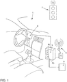
- a vehicle with an exemplary embodiment of the traffic light assistance system according to the invention is explained.
- the vehicle 1 comprises a display device 6 which, in the case shown, is integrated in the combination instrument 6.
- a control device 3 is coupled to this in terms of data technology. Graphics data are generated by the control device 3, transmitted to the output unit 6 and output there.
- the control device 3 comprises a traffic light assistance device 4a and a longitudinal control system 4b.
- the control device 3 is also coupled to a drive unit 9 of the vehicle 1 and can automatically regulate the drive of the vehicle 1 by generating signals and transmitting them to the drive unit 9 so that, for example, the vehicle 1 is accelerated or decelerated.
- control device 3 is coupled to a detection unit 10, which in turn comprises a communication device 5 that can wirelessly communicate with a traffic light 7.
- the acquisition unit 10 can acquire information on the switching times of the traffic light 7 in this way.
- the acquisition unit 10 records information about the vehicle 1, in particular its position relative to the traffic light 7 and its speed v 1 , as well as the distance to a vehicle traveling ahead, provided that such a vehicle is in front of the vehicle 1.
- the vehicle 1 includes an automatic control of the movement of the vehicle 1, the control device 3 generating a display on the display device 6 during an automatic intervention in the control of the vehicle 1, by means of which information about the automatic intervention is output to the driver. For example, a warning message is output if the distance to the vehicle in front is too short and braking is carried out.
- the longitudinal control is automatically regulated, the speed v 1 of the vehicle 1 being regulated.
- the driver of the vehicle 1 is only supported by driving instructions that are displayed by means of the display device 6.
- the control device 3 uses the acquisition unit 10 and its communication device 5 to acquire traffic light phase information from the traffic light 7 and vehicle data of the vehicle 1, in particular the speed v 1 of the vehicle 1 and its position relative to the traffic light 7. Furthermore, vehicles ahead and the distance to them are recorded.
- the control device 3 determines a driving instruction as a function of these data, the traffic light assistance device 4a and the longitudinal control system 4b being integrated as modules in an overall driver assistance system.
- the driving instruction is generated in such a way that the vehicle 1 maintains the safe distance from a vehicle traveling ahead, provided that such a vehicle is detected. Furthermore, the speed v 1 of the vehicle 1 is regulated as a function of the switching times of the traffic light 7 in such a way that the most efficient possible driving behavior is achieved.
- the driving efficiency is calculated using parameters that result from the consequences of the possible driving instructions. In particular, the energy consumption of vehicle 1 is determined, and the travel time to the destination of the route recorded in a navigation system of vehicle 1 is also determined. Furthermore, the vehicle 1 should be controlled in such a way that a uniform flow of traffic is made possible.
- the control device 3 On the basis of the driving instruction generated in this way, the control device 3 generates a signal and transmits it to the drive unit 9, which intervenes accordingly in the drive of the vehicle 1. As a consequence, the vehicle 1 is in particular accelerated or decelerated. Furthermore, the control device 3 generates graphic data and transmits this to the display device 6, where the graphic data are output.
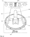
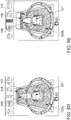
- the display comprises a vehicle symbol 101, which is shown on a virtual roadway 102. There is an arrow 106 in front of the vehicle symbol 101 in the direction of travel.
- the vehicle symbol 101 is surrounded by a warning ring 103, which is divided evenly into eight segments and on which a direction can be indicated from which potential dangers threaten. For example, falling below the safety distance to another vehicle in the vicinity of vehicle 1 can be achieved by highlighting one of the segments of the Warning ring 103 are displayed in order to signal the driver which danger area he must monitor.
- the display also includes a lateral guidance display 105, where arrow symbols can be displayed to the right and left of the vehicle symbol 101 on the virtual lane 102, which can light up when the vehicle 1 approaches the edge of the lane and support the guidance of the vehicle 1 within the lane 2 (please refer Fig. 3 ).
- a display of the setpoint speed 104 In the lower area of the illustration there is a display of the setpoint speed 104.
- the longitudinal control system 4b regulates the speed of the vehicle 1 so that the setpoint speed 104 is reached if this is possible without risk, so as long as z. B. the safety distance to vehicles in front is maintained.
- control objects 107 are shown in the upper area of the display, a traffic light symbol 107a being highlighted in the example shown in order to signal that the traffic light assistance device 4a is active.
- other symbols of rule objects 107 are shown, the associated control being inactive and the symbols therefore being shown "grayed out", i.e. with lower intensity and lower saturation.
- These other symbols of rule objects 107 include, for example, symbols for route guidance and for automated straight-ahead driving.
- the arrow 106 shown is generated in particular as a function of traffic light phase information and vehicle information. This is explained in more detail below.
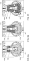
- FIG 3A shows schematically the vehicle 1, which comprises the communication device 5 and is located in the lane 2.
- the vehicle 1 moves at the speed v 1 in the direction of travel F towards the stop line 8.
- the traffic light 7 uses a red light signal to indicate that crossing the stop line 8 is not permitted.
- the vehicle 1 retrieves traffic light phase information from the traffic light 7. Using this information and using vehicle information, such as the speed v 1 of the vehicle 1 and the distance to the stop line 8, it is determined whether the vehicle must stop before the stop line 8 or whether it can drive through without stopping.
- the ones in the Figures 4A and 4B The displays shown can be generated, for example, in order to display acceleration when driving off at a traffic light 7, as in FIG Figure 3D or to indicate a delay as shown in the in Figure 3A situation shown is carried out.
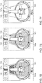
- the representation essentially corresponds to that in Fig. 2 ad already shown.
- the arrow 106 is generated within the scope of the traffic light assistance system according to the invention and adapted to the driving situation.
- the display integrates outputs from the traffic light assistance system and the longitudinal guidance based on the distance from vehicles in front.
- the arrow 106 displayed in front of the vehicle symbol 101 allows measures for controlling the longitudinal guidance of the vehicle 1 to be shown. In particular, changes in speed are shown on the basis of the length of the arrow 106.
- the length of the longitudinal guide arrow 106 is therefore adapted in accordance with the control behavior of the longitudinal control system 4b.
- a longer arrow 106 means that the vehicle 1 is being accelerated, a shorter arrow 106 indicates a deceleration.
- a distinction is also made for the “stop” application in which the vehicle 1 comes to a stop at the end of the braking process.
- the shortest arrow 106 which is also combined with an additional holding line symbol 108, is graphically displayed here.
- the length of the longitudinal guide arrow 106 is thus redundant information for the driver about the Control behavior of the longitudinal control system 4b and is redundant to the perceived driving behavior (for example acceleration of the vehicle 1).
- the Indian Figure 4A The arrow 106 shown in front of the vehicle is longer than the defined initial length as shown in FIG Fig. 2 is shown.
- the arrow 106 extends in Figure 4A almost to the end of the illustrated section of the virtual roadway 102 and therefore signals to the driver of the vehicle 1 that the longitudinal control system 4b is accelerating.
- the arrow 106 shown is shorter than the initial length and thus indicates a delay.
- a particularly short arrow can also signal that the vehicle 1 is being brought to a standstill.
- the display can be generated dynamically, in particular the length of the arrow 106 can change over time or an arrow 106 that is periodically lengthening or shortening can signal the driver that the vehicle 1 is accelerating or decelerating with additional clarity.
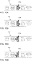
- the vehicle symbol 101 is shown on the virtual lane 102.
- the arrow 106 In front of the vehicle symbol 101 is the arrow 106 pointing in the direction of travel.
- a representation has been integrated into the arrow 106 for the longitudinal control, which has the shape of a herringbone pattern and informs the driver of the planned accelerations and decelerations of the longitudinal control system 4b.
- This herringbone pattern depicts three different system states for the distance-based longitudinal control: acceleration, deceleration and deceleration to stop (standstill).
- the herringbone pattern is thus additional information for the driver about the control behavior of the longitudinal control system 4b and is redundant to the perceived driving behavior (e.g. acceleration of vehicle 1).
- FIG. 5A An acceleration of the vehicle 1 is displayed, for example in the case shown in FIG Figure 3D illustrated situation of approaching a traffic light 7. This is illustrated by a herringbone pattern pointing forward in the direction of travel on the arrow 106. In the case shown, three arrow elements, which are in the direction of travel from Vehicle symbol 101 pointing away, shown. This signals to the driver of vehicle 1 that he is accelerating in the direction of travel.
- FIG. 5B A deceleration of the vehicle 1 is shown, for example in the case shown in FIG Figure 3A
- three arrow elements are also shown here on the arrow 106 pointing in the direction of travel, but in this case the arrow elements point against the direction of travel to the vehicle symbol 101. This signals a delay to the driver of vehicle 1.
- FIG. 5C The example of a display shown signals a deceleration of the vehicle 1 until it comes to a stop, for example in the in Figure 3C situation of stopping in front of a traffic light shown 7.
- a stop for example in the in Figure 3C situation of stopping in front of a traffic light shown 7.
- three arrow elements pointing against the direction of travel are shown on the arrow 106, as a result of which a delay is signaled to the driver.
- a horizontal line is shown, which is also located on arrow 106. The three arrow elements pointing against the direction of travel point to the horizontal line. This signals to the driver of vehicle 1 that a deceleration is being carried out in such a way that vehicle 1 comes to a standstill.
- the number of arrow elements shown on arrow 106 varies depending on the strength of the acceleration or deceleration of vehicle 1. In particular, more arrow elements are displayed with a greater change in speed than with a smaller change in speed. Furthermore, the size of the arrow elements can be adjusted accordingly. In addition, the arrow elements can be displayed dynamically, for example by the appearance of the arrow elements with a time delay, for example in the manner of a running light that moves towards or away from the vehicle symbol 101. This signals the change in speed to the driver.
- a “color carpet” is integrated in the exemplary embodiments shown, which provides the driver with information on the predicted traffic light phase. It consists of the states “green” and “red”. Is possible also the integration of the "yellow phase”.
- the color carpet is dynamic and behaves analogously to the traffic light phase or the status of the traffic light. With the help of this display, the driver can on the one hand see whether he can reach certain traffic light phases or not, on the other hand he can better prepare for an optimized traffic light start.
- the representation of the color carpet is described in detail below: As a function of the traffic light phase information and the speed v 1 and position of the vehicle 1 relative to the traffic light 7, it is determined whether the traffic light 7 is reached at a point in time at which passage is permitted or not. The consequences of a possible change in speed are also determined.
- the display is generated in such a way that it signals to the driver whether or not he will have to stop at the current speed v 1.
- the virtual roadway 102 is divided into areas that are set off from one another by different colors. This type of display is referred to as a “color carpet”, since the impression of a colored and / or patterned background arises on the virtual roadway 102.
- the color green is shown when the journey can be continued uninterrupted, and the color red when it is necessary to stop.
- This is shown in the drawings by different hatching.
- a yellow-colored area can be displayed which corresponds to a third traffic light phase, in particular a transition phase between the “red” and “green” phases.
- the vehicle 1 can continue its journey at the current speed past the traffic light 7, for example in the mode shown in FIG Figure 3D
- the vehicle symbol 101 is therefore located on the green-colored area 102a of the virtual roadway 102.
- the arrow 106 In front of the vehicle symbol 101 is the arrow 106, on which arrow heads pointing in the direction of travel are shown. Acceleration is thus signaled to the driver of vehicle 1.
- the red-colored area 102b of the virtual roadway 102 is located in front of the vehicle symbol 101. This signals to the driver that excessive acceleration will move the vehicle symbol 101 into the red area and that the journey will not take place without stopping at the Stop line 8 may be continued.
- the display shown signals to the driver that he must brake the vehicle 1 in order to avoid stopping at the traffic light 7, for example in the Figures 3A and 3B illustrated situation of delayed passage at a traffic light 7.
- the vehicle symbol 101 is located in this case at the transition between the red-colored area 102b and the green-colored area 102a of the virtual roadway 102.
- An uninterrupted journey is only possible if the speed v 1 of the vehicle 1 is adjusted so that the vehicle symbol 101 is located on the green marked area 102a of the virtual roadway 102.
- the arrow 106 located in front of the vehicle symbol 101 comprises three arrow heads pointing against the direction of travel to the vehicle symbol 101, which signal the driver of the vehicle 1 that the vehicle 1 is decelerating. This signals a change in speed to the driver, which enables uninterrupted progress in traffic.
- the one in the Figure 6C The display shown is generated when stopping the vehicle at the stop line 8 of the traffic light 7 can no longer be avoided, for example in the in the Figures 3A and 3B
- the area 102b of the virtual roadway 102 on which the vehicle symbol 101 is located is colored red.
- the holding line symbol 108 is located at the end of the arrow 106 in front of the vehicle symbol 101 pointing in the direction of travel Figures 6A and 6B A delay is signaled to the driver in the cases shown.
- the holding line symbol 108 indicates that the vehicle 101 is being brought to a standstill.
- the stopping position is selected in such a way that an optimized start of the vehicle 1 can be carried out.
- the optimized start is described below with reference to the Figures 9A through 9G described in detail.
- the position of the stop line symbol 108 therefore does not represent the position of the actual stop line 8, but rather represents the desired stop position of the vehicle 1 in front of the stop line 8.
- the stop line is only displayed if the vehicle has to stop at a signal that is likely to be red.
- the stop line symbol 108 is not displayed.
- the holding line symbol 108 can also serve the driver as an orientation aid for a possibly optimized stop, as will be explained in more detail below.
- the representation also includes a yellow-marked area of the virtual roadway 102. This represents, in particular, the transition between the red phase and the green phase of the traffic light 7.
- FIG. 7A through 7F a sequence of displays for delayed passage at a traffic light is explained, which of an embodiment of the invention Traffic light assistance system can be generated. This corresponds to the approach of the vehicle speed v 1 to a “green wave”, the traffic lights 7 being configured in such a way that several traffic lights 7 can be passed without stopping at an optimal speed. An example of this situation is in the Figures 3A and 3B shown.
- a traffic light located in front of vehicle 1 in the direction of travel was detected and the traffic light assistance system was activated, recognizable from the highlighted traffic light symbol 107a.
- the vehicle symbol 101 is therefore displayed on the red-colored area 102b of the virtual roadway 102.
- the arrow 106 in the direction of travel in front of the vehicle symbol 101 comprises three arrow elements of a herringbone pattern pointing against the direction of travel, which signal the driver that the vehicle 1 needs to be decelerated.
- the representation of the acceleration or deceleration by a herringbone pattern on the arrow 106 has already been described above.
- the vehicle symbol 101 is located completely in the green-colored area 102a of the virtual roadway 102. This signals to the driver that at the current speed v 1 it is possible to drive through the traffic light 7 without stopping. After the stop line 8 has been traversed, with the vehicle 1 moving freely, as in FIG Figure 7E shown, the entire virtual roadway 102 colored green. This signals that the driver is free to travel. Since the vehicle 1 is not in the vicinity of another traffic light 7, the traffic light assistant becomes inactive and the assigned traffic light symbol 107a is hidden. The virtual roadway 102 is no longer shown highlighted in color, as in FIG Figure 7F shown.
- the one in the Figure 8A The display shown is displayed to the driver of the vehicle 1 if there are no traffic lights 7 in the vicinity in front of the vehicle 1.
- the vehicle symbol 101 is located on the virtual roadway 102, and an arrow 106 located in front of the vehicle and pointing in the direction of travel is shown.
- the traffic light symbol 107a is shown in gray, which signals an inactive traffic light assistance system.
- the in Figure 8B shown display If a traffic light 7 is detected in front of the vehicle 1 at which passage is prohibited and at which a stop of the vehicle 1 is unavoidable, the in Figure 8B shown display.
- the traffic light assistance system is activated and the traffic light symbol 107a is highlighted in color.
- the virtual roadway 102 comprises an area 102b marked in red on which the vehicle symbol 101 is located.
- the arrow 106 displayed in front of the vehicle in the direction of travel comprises three arrow elements pointing against the direction of travel and a horizontal line towards which the arrow elements are directed. This signals to the driver of vehicle 1 that braking must be carried out until vehicle 1 comes to a standstill.
- the displays shown are displayed after the vehicle 1 had to stop at a red traffic light 7.
- the vehicle symbol 101 is located on the virtual roadway 102. Ahead the vehicle symbol 101 is shown the arrow symbol 106, which points away from the vehicle 101 in the direction of travel and ends at the holding line symbol 108.
- a message window 109 opens in the upper area of the display. A message shows the driver how long the red phase will last.
- a counter 110 in FIG Figure 9A The display shown indicates that the traffic light 7 will switch to green in 15 seconds.
- the vehicle symbol 101 is therefore located in the red-colored area 102b of the virtual roadway 102, which signals to the driver that no acceleration should be carried out.
- FIG. 9B the display shows ten seconds later and the display signals that traffic light 7 will switch over in five seconds.
- a green-colored area 102a appears on the virtual roadway 102 behind the vehicle symbol 101, which moves forward in the direction of travel as the waiting time expires and signals to the driver that a start can soon be carried out.
- Figure 9C shows the display shortly before the traffic light 7 switches to green.
- a confirmation request which includes a button 112, is displayed in the message window 109.
- the driver Before the vehicle 101 performs an optimized start, the driver must manually confirm this driving maneuver. In the case shown, this is done by touching the button 112 shown on the display, the touch of which is registered by the driver by means of a touch-sensitive surface of the display device 6.
- the confirmation can be carried out by pressing a button on the center console of the vehicle 1.
- the time until the optimized start is carried out is displayed in the message window 109 by the counter 110, in the illustrated case two seconds.
- the transition from the red-colored area 102b to the green-colored area 102a of the virtual roadway 102 shifts further in the direction of travel towards the stop line 108. This signals to the driver when the vehicle 1 is to be started.
- the optimized start is carried out.
- the corresponding display is in Figure 9E shown.
- the holding line symbol 108 is hidden because the vehicle 1 should no longer be stationary.
- the vehicle symbol 101 is located completely in the green marked area 102a of the virtual roadway 102 and that in front of the vehicle symbol 101
- the arrow 106 shown is opposite to the illustration in FIG Figure 9D extended. This signals to the driver that acceleration is being carried out.
- the in Figure 9F The herringbone pattern shown on the arrow 106 with arrow elements pointing in the direction of travel indicates a further acceleration.
- the vehicle 1 accelerates and drives towards the stop line 8 while the traffic light is still red.
- the movement of the vehicle 1 is controlled in such a way that it crosses the stop line 8 at the moment when the traffic light 7 switches to green and thus enables the journey. There is no longer any traffic light 7 in front of vehicle 1 and the traffic light assistance system becomes inactive, as in FIG Figure 9G represented by the grayed out traffic light symbol 107a.
- the Figures 10A to 10D show examples of the symbolic representation of control objects 107, the traffic light assistance system being active for a specific traffic light 7 from a larger number of traffic lights 7.
- the illustration relates to a traffic light 7 which is assigned to a lane to turn off.
- a traffic light symbol 107a is also shown, which in the cases shown comprises an arrow pointing to the right or left.
- the traffic light symbol 107a comprises an arrow pointing to the right, while the arrow in FIG Figure 10B is shown kinking to the right.
- the traffic light symbol 107a includes in FIG Figure 10C a left-pointing arrow that appears in Figure 10D is shown as kinking to the left. This signals to the driver that the display of the traffic light assistance system relates to the traffic light 7 that is assigned to the lane for the respective turning direction.
- the Figures 10E and 10F show representations in which the selection of the lane is indicated by the fact that the vehicle symbol 101 is located on a virtual roadway 102, which in this case is divided into three parts, with a left lane 102l, a straight lane 102g and a right-turn lane 102r being shown.
- the turning lanes to the left 102l and to the right 102r are shown as kinking arrows in the respective direction.
- the vehicle symbol 101 is located in each case on the lane 102l, 102g or 102r on which the real vehicle 1 is also located.
- the color carpet already described above, in which the lane 102 is colored red or green, is used here for each of the individual lanes 102g, 102l and 102r shown. The driver can thus easily see which traffic light phase is to be expected in which lane.
- the vehicle symbol 101 is in the straight lane 102g.
- the vehicle is located in the green-colored area of the lane 102g, as a result of which it is signaled to the driver of the vehicle 1 that he can drive over the traffic light 7 in front of the vehicle in a straight line.
- the vehicle symbol 101 is in the left lane 102l and is here in the red-colored area of the lane 102l. This signals to the driver of the vehicle 1 that the vehicle must be brought to a standstill in front of the stop line 8 at the traffic light 7.
- the two options described above for marking the relevant lane are combined, ie both a traffic light symbol 107a with an arrow in the corresponding direction and several lanes are displayed, the vehicle symbol 101 being on the relevant lane 102g, 102l or 102r is located.
- the number and design of the individual lanes is dependent on the arrangement of the lanes on the real lane 2.
- the display shows the driver driving instructions, which the driver should then actively implement by intervening in the control of the vehicle 1.
- the longitudinal control system 4b is not active or a vehicle 1 does not have such a system.
- the traffic light assistance device 4a generates driving instructions and the control device 3 generates a corresponding display on the display device 6.
Claims (8)
- Système d'assistance aux feux de signalisation destiné à un véhicule (1) et comprenant un dispositif d'affichage (6) destiné au conducteur du véhicule (1) et un dispositif de commande (3) qui est conçu pour générer au moins un élément d'affichage (106) en fonction d'informations de phase de feux de signalisation et d'informations de véhicule et pour présenter l'élément d'affichage (106) par rapport à un symbole de véhicule (101) sur le dispositif d'affichage (6), le dispositif de commande (3) étant conçu pour générer un affichage correspondant sur le dispositif d'affichage (6) et le symbole de véhicule (101) servant de point de référence dans l'affichage, caractérisé en ce que l'élément d'affichage (106) est conçu comme une flèche (106) de longueur variable et est disposé devant le symbole du véhicule (101) dans le sens de déplacement (F) et en ce que la longueur de la flèche (106) dépend de la quantité et/ou de la direction de l'accélération ou de la décélération du véhicule (1).
- Système d'assistance aux feux de signalisation selon la revendication 1, caractérisé en ce que les informations de phase de feux de signalisation peuvent être reçues par le biais d'une interface radio (5) et/ou peuvent être lues dans une base de données.
- Système d'assistance aux feux de signalisation selon la revendication 1 ou 2, caractérisé en ce que les informations de véhicule comprennent une distance entre le véhicule (1) et le feu de signalisation suivant (7) dans le sens de déplacement, une accélération de véhicule et/ou une vitesse d'approche du véhicule (1) par rapport aux feux de signalisation (7).
- Système d'assistance aux feux de signalisation selon l'une des revendications 1 à 3, caractérisé en ce que les informations de véhicule comprennent des paramètres de régulation d'un système de régulation longitudinale (4b) et les paramètres de commande sont formés en fonction des informations de phase de feux de signalisation.
- Système d'assistance aux feux de signalisation selon la revendication 4, caractérisé en ce que le système de régulation longitudinale (4b) est conçu pour générer des paramètres de régulation d'accélération ou de décélération du véhicule (1) de façon à optimiser le déplacement du véhicule (1) devant un feu de signalisation (7) en termes d'efficacité de conduite.
- Système d'assistance aux feux de signalisation selon l'une des revendications précédentes, caractérisé en ce que la flèche (106) comprend un motif à chevrons dont la conception dépend du fait qu'un système de régulation longitudinale activé (4b) accélère le véhicule (1), le décélère ou le décélère jusqu'à l'arrêt et/ou que le véhicule (1) accélérera ou décélérera jusqu'à atteindre le prochain feu (7) dans le sens de déplacement (F) ou décélérera jusqu'à l'arrêt devant le feu de signalisation (7) .
- Système d'assistance aux feux de circulation selon l'une des revendications précédentes, caractérisé en ce que le dispositif de commande (3) est conçu pour présenter une pluralité d'éléments d'affichage (102g ; 102l ; 102r) par rapport au symbole de véhicule (101) sur le dispositif d'affichage (6), les différents éléments d'affichage étant associés à différentes voies de circulation (2) et/ou différents feux de signalisation (7) .
- Système d'assistance aux feux de signalisation selon l'une des revendications précédentes, caractérisé en ce que le dispositif de commande (3) est conçu pour présenter également un symbole de ligne d'arrêt (108) par rapport au symbole de véhicule (101) sur le dispositif d'affichage (6).
Applications Claiming Priority (2)
| Application Number | Priority Date | Filing Date | Title |
|---|---|---|---|
| DE102014208942 | 2014-05-12 | ||
| DE102015204122.0A DE102015204122A1 (de) | 2014-05-12 | 2015-03-06 | Ampelassistenzsystem für ein Fahrzeug mit einer Anzeigeeinrichtung |
Publications (3)
| Publication Number | Publication Date |
|---|---|
| EP2944532A2 EP2944532A2 (fr) | 2015-11-18 |
| EP2944532A3 EP2944532A3 (fr) | 2017-04-26 |
| EP2944532B1 true EP2944532B1 (fr) | 2021-06-30 |
Family
ID=53008393
Family Applications (1)
| Application Number | Title | Priority Date | Filing Date |
|---|---|---|---|
| EP15165689.9A Active EP2944532B1 (fr) | 2014-05-12 | 2015-04-29 | Système d'assistance de feu de circulation pour un véhicule doté d'un dispositif d'affichage |
Country Status (2)
| Country | Link |
|---|---|
| EP (1) | EP2944532B1 (fr) |
| DE (1) | DE102015204122A1 (fr) |
Families Citing this family (35)
| Publication number | Priority date | Publication date | Assignee | Title |
|---|---|---|---|---|
| DE102015207963B4 (de) | 2015-04-29 | 2018-08-02 | Volkswagen Aktiengesellschaft | Verfahren und System zur Handlungsunterstützung |
| DE102015221815B3 (de) * | 2015-07-07 | 2016-12-22 | Volkswagen Aktiengesellschaft | Verfahren zum Steuern und/oder Regeln einer Fahrweise eines Kraftfahrzeugs |
| DE102015224114A1 (de) * | 2015-12-02 | 2017-06-08 | Bayerische Motoren Werke Aktiengesellschaft | Getriebesteuereinrichtung |
| FR3045545A1 (fr) * | 2015-12-21 | 2017-06-23 | Peugeot Citroen Automobiles Sa | Dispositif d’aide a la conduite |
| JP6814161B2 (ja) * | 2015-12-22 | 2021-01-13 | 株式会社小糸製作所 | 車両用照明装置、車両及び照明制御システム |
| DE102016204096B4 (de) * | 2016-03-11 | 2022-02-17 | Volkswagen Aktiengesellschaft | Verfahren zum Betreiben des Fahrerassistenzsystems und Fahrerassistenzsystem |
| DE102016208793A1 (de) * | 2016-05-20 | 2017-11-23 | Zf Friedrichshafen Ag | Verkehrsampel-Assistent |
| DE102016007012B4 (de) | 2016-06-09 | 2018-07-19 | Audi Ag | Verfahren zum Unterstützen eines Fahrers |
| DE102016009238A1 (de) | 2016-07-28 | 2017-02-16 | Daimler Ag | Verfahren zur Anzeige einer Ampel in einem Fahrzeug |
| DE102016217558A1 (de) | 2016-09-14 | 2018-03-15 | Continental Teves Ag & Co. Ohg | Verfahren zum Zuordnen einer Ampel zu einer Fahrspur, Fahrzeug und Speichermedium |
| DE102016011834A1 (de) | 2016-09-24 | 2017-04-13 | Daimler Ag | Verfahren zur Ausgabe zumindest einer verkehrsrelevanten Information |
| WO2018125128A1 (fr) * | 2016-12-29 | 2018-07-05 | Demetrius Thompson | Système de conduite sûr générant des points sur une carte |
| DE102017204592A1 (de) * | 2017-03-20 | 2018-09-20 | Robert Bosch Gmbh | Verfahren und Vorrichtung zum Anzeigen eines bevorstehenden Fahrmanövers für ein hochautomatisiertes Fahrzeug |
| DE102017208386A1 (de) | 2017-05-18 | 2018-11-22 | Ford Global Technologies, Llc | Verfahren zum unterstützenden Steuern eines Fahrzeugs, Assistenzsystem sowie Fahrzeug |
| DE102017208646A1 (de) * | 2017-05-22 | 2018-11-22 | Audi Ag | Verfahren zum Betreiben eines Kraftfahrzeugs sowie ein Kraftfahrzeug |
| DE102017221191B4 (de) | 2017-11-27 | 2019-06-13 | Volkswagen Aktiengesellschaft | Verfahren zur Anzeige des Verlaufs einer Sicherheitszone vor einem Fahrzeug oder einem Objekt mit einer Anzeigeeinheit, Vorrichtung zur Durchführung des Verfahrens sowie Kraftfahrzeug und Computerprogramm |
| DE102018203353A1 (de) | 2018-03-07 | 2019-09-12 | Bayerische Motoren Werke Aktiengesellschaft | Steuereinheit und Verfahren zum Betreiben einer Fahrfunktion an einer Signalisierungsanlage |
| DE102018205753A1 (de) * | 2018-04-16 | 2019-10-17 | Bayerische Motoren Werke Aktiengesellschaft | Verfahren, Vorrichtung und Fortbewegungsmittel für ein automatisiertes Anfahren eines Fortbewegungsmittels an einer Lichtsignalanlage |
| JP7110729B2 (ja) * | 2018-05-25 | 2022-08-02 | トヨタ自動車株式会社 | 自動運転システム及び自動運転システムの制御方法 |
| FR3085146A1 (fr) * | 2018-08-24 | 2020-02-28 | Psa Automobiles Sa | Procede et dispositif d’assistance a la conduite d’un vehicule lors d’un passage de feu tricolore, par affichage d’informations comportementales |
| FR3085147A1 (fr) * | 2018-08-24 | 2020-02-28 | Psa Automobiles Sa | Assistance a la conduite d’un vehicule lors d’un passage de feu tricolore, par affichage de ses couleurs en cours et future |
| DE102018123259A1 (de) * | 2018-09-21 | 2020-03-26 | Robert Bosch Gmbh | System und Verfahren zum Ermitteln eines Signalbilds eines Signalgebers einer Lichtsignalanlage |
| DE102018216383B4 (de) * | 2018-09-25 | 2023-12-07 | Audi Ag | Verfahren und Steuereinrichtung zum Betreiben einer am Kopf tragbaren Anzeigeeinrichtung in einem Kraftfahrzeug |
| CN109484411B (zh) * | 2018-10-25 | 2020-07-10 | 衢州学院 | 一种基于大数据的车辆行驶状态检测方法 |
| FR3108083B1 (fr) * | 2020-03-10 | 2022-09-02 | Psa Automobiles Sa | Système de conduite automatisée avec dispositif d’information du conducteur. |
| US20210348932A1 (en) * | 2020-05-08 | 2021-11-11 | George Mason University | Systems and methods for coordinating traffic lights |
| DE102020126670A1 (de) | 2020-10-12 | 2022-04-14 | Bayerische Motoren Werke Aktiengesellschaft | Fahrzeugführungssystem und Verfahren zum Betreiben einer Fahrfunktion in unterschiedlichen Modi |
| DE102020126673A1 (de) * | 2020-10-12 | 2022-04-14 | Bayerische Motoren Werke Aktiengesellschaft | Fahrzeugführungssystem und Verfahren zur Ausgabe von Information in Bezug auf eine Signalisierungseinheit |
| DE102020126671A1 (de) | 2020-10-12 | 2022-04-14 | Bayerische Motoren Werke Aktiengesellschaft | Fahrzeugführungssystem und Verfahren zum Betreiben einer Fahrfunktion bei einer Konfigurationsänderung |
| DE102020007229A1 (de) | 2020-11-20 | 2022-05-25 | Enno Hilliger | Fahrassistenzsystem, beispielweise zum zeitoptimierten Durchfahren von zeitabhängigen Verkehrseinschränkungen |
| CN112489460A (zh) | 2020-12-03 | 2021-03-12 | 百度国际科技(深圳)有限公司 | 信号灯信息的输出方法和装置 |
| DE102021104120A1 (de) | 2021-02-22 | 2022-08-25 | Bayerische Motoren Werke Aktiengesellschaft | Fahrzeugführungssystem und Verfahren zum Betreiben einer Fahrfunktion an einem Verkehrs-Knotenpunkt |
| KR102652486B1 (ko) * | 2021-09-24 | 2024-03-29 | (주)오토노머스에이투지 | 라이다를 이용한 신호등 정보 예측 방법 및 이를 이용한 서버 |
| CN115050194A (zh) * | 2022-06-10 | 2022-09-13 | 绿波速度(浙江)科技有限公司 | 一种应用于一般道路的分布式智能led绿波电子显示系统 |
| DE102022124616A1 (de) * | 2022-09-26 | 2024-03-28 | Bayerische Motoren Werke Aktiengesellschaft | Fahrzeugführungsvorrichtung und Verfahren zum Betrieb eines Fahrzeugs an einer Vorfahrtstelle |
Family Cites Families (5)
| Publication number | Priority date | Publication date | Assignee | Title |
|---|---|---|---|---|
| US20080030372A1 (en) * | 2006-08-02 | 2008-02-07 | Guixian Lu | Traffic light prediction system |
| DE102008019461A1 (de) * | 2008-04-18 | 2009-10-22 | Daimler Ag | Vorrichtung und Verfahren zur Anzeige von Informationen in einem Fahrzeug |
| DE102008020728B4 (de) * | 2008-04-25 | 2011-06-16 | Man Nutzfahrzeuge Aktiengesellschaft | Verkehrszeichenassistenzsystem |
| DE102008051385A1 (de) * | 2008-10-11 | 2010-04-15 | Man Nutzfahrzeuge Aktiengesellschaft | Optisches Anzeigesystem |
| DE102013003565A1 (de) * | 2013-03-01 | 2013-09-19 | Daimler Ag | Verfahren zur automatischen Längsregelung eines Fahrzeuges |
-
2015
- 2015-03-06 DE DE102015204122.0A patent/DE102015204122A1/de not_active Withdrawn
- 2015-04-29 EP EP15165689.9A patent/EP2944532B1/fr active Active
Also Published As
| Publication number | Publication date |
|---|---|
| EP2944532A3 (fr) | 2017-04-26 |
| EP2944532A2 (fr) | 2015-11-18 |
| DE102015204122A1 (de) | 2015-11-12 |
Similar Documents
| Publication | Publication Date | Title |
|---|---|---|
| EP2944532B1 (fr) | Système d'assistance de feu de circulation pour un véhicule doté d'un dispositif d'affichage | |
| EP2349805B1 (fr) | Procédé de commande d'un véhicule automobile et dispositif correspondant | |
| EP2881829B1 (fr) | Procédé destiné à la commande automatique d'un véhicule, dispositif de production de signaux de commande pour un véhicule et véhicule | |
| EP2812202B1 (fr) | Dispositif pour le guidage automatique d'un véhicule automobile, véhicule automobile avec un tel dispositif et procédé pour opérer un véhicule automobile | |
| EP2216197B1 (fr) | Procédé de commande d'un système d'assistance du conducteur et système d'assistance du conducteur | |
| EP2771227B1 (fr) | Procédé pour conduire un véhicule et système d'assistance au conducteur | |
| EP3250426B1 (fr) | Procédé et dispositif pour faire fonctionner un véhicule | |
| EP3269579B1 (fr) | Procede de fonctionnement d'un systeme d'informations et systeme d'informations | |
| DE19958520A1 (de) | Geschwindigkeitsregler für ein Kraftfahrzeug | |
| DE102012215060A1 (de) | Verfahren zum Führen eines Fahrzeugs und Fahrerassistenzsystem | |
| EP3180221B1 (fr) | Système d'aide au conducteur | |
| WO2020078810A1 (fr) | Procédé de visualisation d'un lieu de passage sur une route | |
| EP2862156A1 (fr) | Formation d'une voie réservée aux secours | |
| EP3138752B1 (fr) | Procede et systeme destines a assister un utilisateur lors de la planification et l'execution d'un parcours routier avec son vehicule | |
| EP2669109B1 (fr) | Système d'assistance de manoeuvre | |
| EP3569465A1 (fr) | Dispositif et système de fourniture d'une fonction d'automatisation pour un véhicule | |
| DE102007036417A1 (de) | Verfahren zum Betreiben eines Abstandsregelsystems für Fahrzeuge | |
| DE102021109105A1 (de) | Navigationssystem und Verfahren zur Anzeige einer Navigationskarte | |
| WO2019233719A1 (fr) | Procédé et dispositif pour assister un conducteur dans un véhicule | |
| EP3592604A1 (fr) | Véhicule automobile comprenant un module d'éclairage servant à générer un symbole | |
| DE102021203551A1 (de) | Fahrintentionserkennung | |
| DE10337842A1 (de) | Vorrichtung zur semiautonomen Unterstützung des Einparkvorgangs bei Fahrzeugen | |
| DE102020102328A1 (de) | Verfahren und Assistenzsystem zur Fahrzeugsteuerung und Kraftfahrzeug | |
| WO2010045903A1 (fr) | Dispositif et procédé pour commander et/ou réguler un véhicule au moyen d'informations concernant des véhicules circulant sur des voies adjacentes | |
| EP3747720B1 (fr) | Procédé de fonctionnement d'un véhicule pourvu d'une pluralité de modes semi-automatiques à commande de bracquage manuell et à commande de bracquage non manuell, ainsi que système de guidage de véhicule |
Legal Events
| Date | Code | Title | Description |
|---|---|---|---|
| PUAI | Public reference made under article 153(3) epc to a published international application that has entered the european phase |
Free format text: ORIGINAL CODE: 0009012 |
|
| AK | Designated contracting states |
Kind code of ref document: A2 Designated state(s): AL AT BE BG CH CY CZ DE DK EE ES FI FR GB GR HR HU IE IS IT LI LT LU LV MC MK MT NL NO PL PT RO RS SE SI SK SM TR |
|
| AX | Request for extension of the european patent |
Extension state: BA ME |
|
| PUAL | Search report despatched |
Free format text: ORIGINAL CODE: 0009013 |
|
| AK | Designated contracting states |
Kind code of ref document: A3 Designated state(s): AL AT BE BG CH CY CZ DE DK EE ES FI FR GB GR HR HU IE IS IT LI LT LU LV MC MK MT NL NO PL PT RO RS SE SI SK SM TR |
|
| AX | Request for extension of the european patent |
Extension state: BA ME |
|
| RIC1 | Information provided on ipc code assigned before grant |
Ipc: B60K 35/00 20060101ALI20170320BHEP Ipc: B60W 30/17 20120101ALN20170320BHEP Ipc: B60W 50/00 20060101ALI20170320BHEP Ipc: B60W 30/14 20060101ALI20170320BHEP Ipc: G08G 1/0967 20060101ALN20170320BHEP Ipc: B60W 50/14 20120101AFI20170320BHEP |
|
| STAA | Information on the status of an ep patent application or granted ep patent |
Free format text: STATUS: REQUEST FOR EXAMINATION WAS MADE |
|
| 17P | Request for examination filed |
Effective date: 20171026 |
|
| RBV | Designated contracting states (corrected) |
Designated state(s): AL AT BE BG CH CY CZ DE DK EE ES FI FR GB GR HR HU IE IS IT LI LT LU LV MC MK MT NL NO PL PT RO RS SE SI SK SM TR |
|
| GRAP | Despatch of communication of intention to grant a patent |
Free format text: ORIGINAL CODE: EPIDOSNIGR1 |
|
| STAA | Information on the status of an ep patent application or granted ep patent |
Free format text: STATUS: GRANT OF PATENT IS INTENDED |
|
| INTG | Intention to grant announced |
Effective date: 20210416 |
|
| GRAS | Grant fee paid |
Free format text: ORIGINAL CODE: EPIDOSNIGR3 |
|
| GRAA | (expected) grant |
Free format text: ORIGINAL CODE: 0009210 |
|
| STAA | Information on the status of an ep patent application or granted ep patent |
Free format text: STATUS: THE PATENT HAS BEEN GRANTED |
|
| AK | Designated contracting states |
Kind code of ref document: B1 Designated state(s): AL AT BE BG CH CY CZ DE DK EE ES FI FR GB GR HR HU IE IS IT LI LT LU LV MC MK MT NL NO PL PT RO RS SE SI SK SM TR |
|
| REG | Reference to a national code |
Ref country code: CH Ref legal event code: EP |
|
| REG | Reference to a national code |
Ref country code: AT Ref legal event code: REF Ref document number: 1406110 Country of ref document: AT Kind code of ref document: T Effective date: 20210715 |
|
| REG | Reference to a national code |
Ref country code: DE Ref legal event code: R096 Ref document number: 502015014866 Country of ref document: DE |
|
| REG | Reference to a national code |
Ref country code: IE Ref legal event code: FG4D Free format text: LANGUAGE OF EP DOCUMENT: GERMAN |
|
| REG | Reference to a national code |
Ref country code: LT Ref legal event code: MG9D |
|
| PG25 | Lapsed in a contracting state [announced via postgrant information from national office to epo] |
Ref country code: HR Free format text: LAPSE BECAUSE OF FAILURE TO SUBMIT A TRANSLATION OF THE DESCRIPTION OR TO PAY THE FEE WITHIN THE PRESCRIBED TIME-LIMIT Effective date: 20210630 Ref country code: BG Free format text: LAPSE BECAUSE OF FAILURE TO SUBMIT A TRANSLATION OF THE DESCRIPTION OR TO PAY THE FEE WITHIN THE PRESCRIBED TIME-LIMIT Effective date: 20210930 Ref country code: FI Free format text: LAPSE BECAUSE OF FAILURE TO SUBMIT A TRANSLATION OF THE DESCRIPTION OR TO PAY THE FEE WITHIN THE PRESCRIBED TIME-LIMIT Effective date: 20210630 |
|
| REG | Reference to a national code |
Ref country code: NL Ref legal event code: MP Effective date: 20210630 |
|
| PG25 | Lapsed in a contracting state [announced via postgrant information from national office to epo] |
Ref country code: LV Free format text: LAPSE BECAUSE OF FAILURE TO SUBMIT A TRANSLATION OF THE DESCRIPTION OR TO PAY THE FEE WITHIN THE PRESCRIBED TIME-LIMIT Effective date: 20210630 Ref country code: GR Free format text: LAPSE BECAUSE OF FAILURE TO SUBMIT A TRANSLATION OF THE DESCRIPTION OR TO PAY THE FEE WITHIN THE PRESCRIBED TIME-LIMIT Effective date: 20211001 Ref country code: SE Free format text: LAPSE BECAUSE OF FAILURE TO SUBMIT A TRANSLATION OF THE DESCRIPTION OR TO PAY THE FEE WITHIN THE PRESCRIBED TIME-LIMIT Effective date: 20210630 Ref country code: RS Free format text: LAPSE BECAUSE OF FAILURE TO SUBMIT A TRANSLATION OF THE DESCRIPTION OR TO PAY THE FEE WITHIN THE PRESCRIBED TIME-LIMIT Effective date: 20210630 Ref country code: NO Free format text: LAPSE BECAUSE OF FAILURE TO SUBMIT A TRANSLATION OF THE DESCRIPTION OR TO PAY THE FEE WITHIN THE PRESCRIBED TIME-LIMIT Effective date: 20210930 |
|
| PG25 | Lapsed in a contracting state [announced via postgrant information from national office to epo] |
Ref country code: SM Free format text: LAPSE BECAUSE OF FAILURE TO SUBMIT A TRANSLATION OF THE DESCRIPTION OR TO PAY THE FEE WITHIN THE PRESCRIBED TIME-LIMIT Effective date: 20210630 Ref country code: SK Free format text: LAPSE BECAUSE OF FAILURE TO SUBMIT A TRANSLATION OF THE DESCRIPTION OR TO PAY THE FEE WITHIN THE PRESCRIBED TIME-LIMIT Effective date: 20210630 Ref country code: CZ Free format text: LAPSE BECAUSE OF FAILURE TO SUBMIT A TRANSLATION OF THE DESCRIPTION OR TO PAY THE FEE WITHIN THE PRESCRIBED TIME-LIMIT Effective date: 20210630 Ref country code: EE Free format text: LAPSE BECAUSE OF FAILURE TO SUBMIT A TRANSLATION OF THE DESCRIPTION OR TO PAY THE FEE WITHIN THE PRESCRIBED TIME-LIMIT Effective date: 20210630 Ref country code: RO Free format text: LAPSE BECAUSE OF FAILURE TO SUBMIT A TRANSLATION OF THE DESCRIPTION OR TO PAY THE FEE WITHIN THE PRESCRIBED TIME-LIMIT Effective date: 20210630 Ref country code: PT Free format text: LAPSE BECAUSE OF FAILURE TO SUBMIT A TRANSLATION OF THE DESCRIPTION OR TO PAY THE FEE WITHIN THE PRESCRIBED TIME-LIMIT Effective date: 20211102 Ref country code: NL Free format text: LAPSE BECAUSE OF FAILURE TO SUBMIT A TRANSLATION OF THE DESCRIPTION OR TO PAY THE FEE WITHIN THE PRESCRIBED TIME-LIMIT Effective date: 20210630 Ref country code: ES Free format text: LAPSE BECAUSE OF FAILURE TO SUBMIT A TRANSLATION OF THE DESCRIPTION OR TO PAY THE FEE WITHIN THE PRESCRIBED TIME-LIMIT Effective date: 20210630 |
|
| PG25 | Lapsed in a contracting state [announced via postgrant information from national office to epo] |
Ref country code: PL Free format text: LAPSE BECAUSE OF FAILURE TO SUBMIT A TRANSLATION OF THE DESCRIPTION OR TO PAY THE FEE WITHIN THE PRESCRIBED TIME-LIMIT Effective date: 20210630 |
|
| REG | Reference to a national code |
Ref country code: DE Ref legal event code: R097 Ref document number: 502015014866 Country of ref document: DE |
|
| PG25 | Lapsed in a contracting state [announced via postgrant information from national office to epo] |
Ref country code: DK Free format text: LAPSE BECAUSE OF FAILURE TO SUBMIT A TRANSLATION OF THE DESCRIPTION OR TO PAY THE FEE WITHIN THE PRESCRIBED TIME-LIMIT Effective date: 20210630 |
|
| PLBE | No opposition filed within time limit |
Free format text: ORIGINAL CODE: 0009261 |
|
| STAA | Information on the status of an ep patent application or granted ep patent |
Free format text: STATUS: NO OPPOSITION FILED WITHIN TIME LIMIT |
|
| PG25 | Lapsed in a contracting state [announced via postgrant information from national office to epo] |
Ref country code: AL Free format text: LAPSE BECAUSE OF FAILURE TO SUBMIT A TRANSLATION OF THE DESCRIPTION OR TO PAY THE FEE WITHIN THE PRESCRIBED TIME-LIMIT Effective date: 20210630 |
|
| 26N | No opposition filed |
Effective date: 20220331 |
|
| PG25 | Lapsed in a contracting state [announced via postgrant information from national office to epo] |
Ref country code: IT Free format text: LAPSE BECAUSE OF FAILURE TO SUBMIT A TRANSLATION OF THE DESCRIPTION OR TO PAY THE FEE WITHIN THE PRESCRIBED TIME-LIMIT Effective date: 20210630 |
|
| REG | Reference to a national code |
Ref country code: CH Ref legal event code: PL |
|
| REG | Reference to a national code |
Ref country code: BE Ref legal event code: MM Effective date: 20220430 |
|
| PG25 | Lapsed in a contracting state [announced via postgrant information from national office to epo] |
Ref country code: MC Free format text: LAPSE BECAUSE OF FAILURE TO SUBMIT A TRANSLATION OF THE DESCRIPTION OR TO PAY THE FEE WITHIN THE PRESCRIBED TIME-LIMIT Effective date: 20210630 Ref country code: LU Free format text: LAPSE BECAUSE OF NON-PAYMENT OF DUE FEES Effective date: 20220429 Ref country code: LI Free format text: LAPSE BECAUSE OF NON-PAYMENT OF DUE FEES Effective date: 20220430 Ref country code: CH Free format text: LAPSE BECAUSE OF NON-PAYMENT OF DUE FEES Effective date: 20220430 |
|
| PG25 | Lapsed in a contracting state [announced via postgrant information from national office to epo] |
Ref country code: BE Free format text: LAPSE BECAUSE OF NON-PAYMENT OF DUE FEES Effective date: 20220430 |
|
| PG25 | Lapsed in a contracting state [announced via postgrant information from national office to epo] |
Ref country code: LT Free format text: LAPSE BECAUSE OF FAILURE TO SUBMIT A TRANSLATION OF THE DESCRIPTION OR TO PAY THE FEE WITHIN THE PRESCRIBED TIME-LIMIT Effective date: 20210630 Ref country code: IE Free format text: LAPSE BECAUSE OF NON-PAYMENT OF DUE FEES Effective date: 20220429 |
|
| REG | Reference to a national code |
Ref country code: AT Ref legal event code: MM01 Ref document number: 1406110 Country of ref document: AT Kind code of ref document: T Effective date: 20220429 |
|
| P01 | Opt-out of the competence of the unified patent court (upc) registered |
Effective date: 20230523 |
|
| PG25 | Lapsed in a contracting state [announced via postgrant information from national office to epo] |
Ref country code: AT Free format text: LAPSE BECAUSE OF NON-PAYMENT OF DUE FEES Effective date: 20220429 |
|
| PGFP | Annual fee paid to national office [announced via postgrant information from national office to epo] |
Ref country code: FR Payment date: 20230421 Year of fee payment: 9 Ref country code: DE Payment date: 20230430 Year of fee payment: 9 |
|
| PGFP | Annual fee paid to national office [announced via postgrant information from national office to epo] |
Ref country code: GB Payment date: 20230418 Year of fee payment: 9 |
|
| PG25 | Lapsed in a contracting state [announced via postgrant information from national office to epo] |
Ref country code: HU Free format text: LAPSE BECAUSE OF FAILURE TO SUBMIT A TRANSLATION OF THE DESCRIPTION OR TO PAY THE FEE WITHIN THE PRESCRIBED TIME-LIMIT; INVALID AB INITIO Effective date: 20150429 |
|
| PG25 | Lapsed in a contracting state [announced via postgrant information from national office to epo] |
Ref country code: MK Free format text: LAPSE BECAUSE OF FAILURE TO SUBMIT A TRANSLATION OF THE DESCRIPTION OR TO PAY THE FEE WITHIN THE PRESCRIBED TIME-LIMIT Effective date: 20210630 Ref country code: CY Free format text: LAPSE BECAUSE OF FAILURE TO SUBMIT A TRANSLATION OF THE DESCRIPTION OR TO PAY THE FEE WITHIN THE PRESCRIBED TIME-LIMIT Effective date: 20210630 |