EP2944532B1 - Traffic light assisting system for a vehicle with a display device - Google Patents
Traffic light assisting system for a vehicle with a display device Download PDFInfo
- Publication number
- EP2944532B1 EP2944532B1 EP15165689.9A EP15165689A EP2944532B1 EP 2944532 B1 EP2944532 B1 EP 2944532B1 EP 15165689 A EP15165689 A EP 15165689A EP 2944532 B1 EP2944532 B1 EP 2944532B1
- Authority
- EP
- European Patent Office
- Prior art keywords
- vehicle
- traffic light
- display
- symbol
- driver
- Prior art date
- Legal status (The legal status is an assumption and is not a legal conclusion. Google has not performed a legal analysis and makes no representation as to the accuracy of the status listed.)
- Active
Links
- 230000001133 acceleration Effects 0.000 claims description 31
- 230000033001 locomotion Effects 0.000 claims description 14
- 230000033228 biological regulation Effects 0.000 claims description 9
- 230000001105 regulatory effect Effects 0.000 claims description 6
- 230000001419 dependent effect Effects 0.000 claims description 5
- 238000013459 approach Methods 0.000 claims description 4
- 230000008859 change Effects 0.000 description 12
- 238000004891 communication Methods 0.000 description 9
- 238000000034 method Methods 0.000 description 8
- 230000008569 process Effects 0.000 description 8
- 230000009471 action Effects 0.000 description 6
- 238000011161 development Methods 0.000 description 6
- 230000018109 developmental process Effects 0.000 description 6
- 238000005265 energy consumption Methods 0.000 description 6
- 230000010354 integration Effects 0.000 description 5
- 230000003111 delayed effect Effects 0.000 description 4
- 230000007704 transition Effects 0.000 description 4
- 239000003086 colorant Substances 0.000 description 3
- 238000012790 confirmation Methods 0.000 description 3
- 230000006978 adaptation Effects 0.000 description 2
- 230000000454 anti-cipatory effect Effects 0.000 description 2
- 238000001514 detection method Methods 0.000 description 2
- 230000012447 hatching Effects 0.000 description 2
- 230000003466 anti-cipated effect Effects 0.000 description 1
- 210000000988 bone and bone Anatomy 0.000 description 1
- 230000001276 controlling effect Effects 0.000 description 1
- 230000007423 decrease Effects 0.000 description 1
- 238000013461 design Methods 0.000 description 1
- 230000000694 effects Effects 0.000 description 1
- 238000005516 engineering process Methods 0.000 description 1
- 239000000446 fuel Substances 0.000 description 1
- 230000006872 improvement Effects 0.000 description 1
- 238000013507 mapping Methods 0.000 description 1
- 238000005457 optimization Methods 0.000 description 1
- 238000003825 pressing Methods 0.000 description 1
- 230000009467 reduction Effects 0.000 description 1
- 238000004904 shortening Methods 0.000 description 1
Images


Classifications
-
- G—PHYSICS
- G08—SIGNALLING
- G08G—TRAFFIC CONTROL SYSTEMS
- G08G1/00—Traffic control systems for road vehicles
- G08G1/09—Arrangements for giving variable traffic instructions
- G08G1/0962—Arrangements for giving variable traffic instructions having an indicator mounted inside the vehicle, e.g. giving voice messages
- G08G1/0967—Systems involving transmission of highway information, e.g. weather, speed limits
- G08G1/096708—Systems involving transmission of highway information, e.g. weather, speed limits where the received information might be used to generate an automatic action on the vehicle control
- G08G1/096716—Systems involving transmission of highway information, e.g. weather, speed limits where the received information might be used to generate an automatic action on the vehicle control where the received information does not generate an automatic action on the vehicle control
-
- B—PERFORMING OPERATIONS; TRANSPORTING
- B60—VEHICLES IN GENERAL
- B60K—ARRANGEMENT OR MOUNTING OF PROPULSION UNITS OR OF TRANSMISSIONS IN VEHICLES; ARRANGEMENT OR MOUNTING OF PLURAL DIVERSE PRIME-MOVERS IN VEHICLES; AUXILIARY DRIVES FOR VEHICLES; INSTRUMENTATION OR DASHBOARDS FOR VEHICLES; ARRANGEMENTS IN CONNECTION WITH COOLING, AIR INTAKE, GAS EXHAUST OR FUEL SUPPLY OF PROPULSION UNITS IN VEHICLES
- B60K35/00—Arrangement of adaptations of instruments
-
- B60K35/10—
-
- B60K35/28—
-
- B—PERFORMING OPERATIONS; TRANSPORTING
- B60—VEHICLES IN GENERAL
- B60W—CONJOINT CONTROL OF VEHICLE SUB-UNITS OF DIFFERENT TYPE OR DIFFERENT FUNCTION; CONTROL SYSTEMS SPECIALLY ADAPTED FOR HYBRID VEHICLES; ROAD VEHICLE DRIVE CONTROL SYSTEMS FOR PURPOSES NOT RELATED TO THE CONTROL OF A PARTICULAR SUB-UNIT
- B60W30/00—Purposes of road vehicle drive control systems not related to the control of a particular sub-unit, e.g. of systems using conjoint control of vehicle sub-units, or advanced driver assistance systems for ensuring comfort, stability and safety or drive control systems for propelling or retarding the vehicle
- B60W30/14—Adaptive cruise control
- B60W30/143—Speed control
-
- B—PERFORMING OPERATIONS; TRANSPORTING
- B60—VEHICLES IN GENERAL
- B60W—CONJOINT CONTROL OF VEHICLE SUB-UNITS OF DIFFERENT TYPE OR DIFFERENT FUNCTION; CONTROL SYSTEMS SPECIALLY ADAPTED FOR HYBRID VEHICLES; ROAD VEHICLE DRIVE CONTROL SYSTEMS FOR PURPOSES NOT RELATED TO THE CONTROL OF A PARTICULAR SUB-UNIT
- B60W30/00—Purposes of road vehicle drive control systems not related to the control of a particular sub-unit, e.g. of systems using conjoint control of vehicle sub-units, or advanced driver assistance systems for ensuring comfort, stability and safety or drive control systems for propelling or retarding the vehicle
- B60W30/18—Propelling the vehicle
- B60W30/18009—Propelling the vehicle related to particular drive situations
- B60W30/18154—Approaching an intersection
-
- B—PERFORMING OPERATIONS; TRANSPORTING
- B60—VEHICLES IN GENERAL
- B60W—CONJOINT CONTROL OF VEHICLE SUB-UNITS OF DIFFERENT TYPE OR DIFFERENT FUNCTION; CONTROL SYSTEMS SPECIALLY ADAPTED FOR HYBRID VEHICLES; ROAD VEHICLE DRIVE CONTROL SYSTEMS FOR PURPOSES NOT RELATED TO THE CONTROL OF A PARTICULAR SUB-UNIT
- B60W50/00—Details of control systems for road vehicle drive control not related to the control of a particular sub-unit, e.g. process diagnostic or vehicle driver interfaces
- B60W50/0097—Predicting future conditions
-
- B—PERFORMING OPERATIONS; TRANSPORTING
- B60—VEHICLES IN GENERAL
- B60W—CONJOINT CONTROL OF VEHICLE SUB-UNITS OF DIFFERENT TYPE OR DIFFERENT FUNCTION; CONTROL SYSTEMS SPECIALLY ADAPTED FOR HYBRID VEHICLES; ROAD VEHICLE DRIVE CONTROL SYSTEMS FOR PURPOSES NOT RELATED TO THE CONTROL OF A PARTICULAR SUB-UNIT
- B60W50/00—Details of control systems for road vehicle drive control not related to the control of a particular sub-unit, e.g. process diagnostic or vehicle driver interfaces
- B60W50/08—Interaction between the driver and the control system
- B60W50/14—Means for informing the driver, warning the driver or prompting a driver intervention
-
- G—PHYSICS
- G08—SIGNALLING
- G08G—TRAFFIC CONTROL SYSTEMS
- G08G1/00—Traffic control systems for road vehicles
- G08G1/09—Arrangements for giving variable traffic instructions
- G08G1/0962—Arrangements for giving variable traffic instructions having an indicator mounted inside the vehicle, e.g. giving voice messages
- G08G1/09626—Arrangements for giving variable traffic instructions having an indicator mounted inside the vehicle, e.g. giving voice messages where the origin of the information is within the own vehicle, e.g. a local storage device, digital map
-
- G—PHYSICS
- G08—SIGNALLING
- G08G—TRAFFIC CONTROL SYSTEMS
- G08G1/00—Traffic control systems for road vehicles
- G08G1/09—Arrangements for giving variable traffic instructions
- G08G1/0962—Arrangements for giving variable traffic instructions having an indicator mounted inside the vehicle, e.g. giving voice messages
- G08G1/0967—Systems involving transmission of highway information, e.g. weather, speed limits
- G08G1/096708—Systems involving transmission of highway information, e.g. weather, speed limits where the received information might be used to generate an automatic action on the vehicle control
- G08G1/096725—Systems involving transmission of highway information, e.g. weather, speed limits where the received information might be used to generate an automatic action on the vehicle control where the received information generates an automatic action on the vehicle control
-
- G—PHYSICS
- G08—SIGNALLING
- G08G—TRAFFIC CONTROL SYSTEMS
- G08G1/00—Traffic control systems for road vehicles
- G08G1/09—Arrangements for giving variable traffic instructions
- G08G1/0962—Arrangements for giving variable traffic instructions having an indicator mounted inside the vehicle, e.g. giving voice messages
- G08G1/0967—Systems involving transmission of highway information, e.g. weather, speed limits
- G08G1/096733—Systems involving transmission of highway information, e.g. weather, speed limits where a selection of the information might take place
- G08G1/096758—Systems involving transmission of highway information, e.g. weather, speed limits where a selection of the information might take place where no selection takes place on the transmitted or the received information
-
- G—PHYSICS
- G08—SIGNALLING
- G08G—TRAFFIC CONTROL SYSTEMS
- G08G1/00—Traffic control systems for road vehicles
- G08G1/09—Arrangements for giving variable traffic instructions
- G08G1/0962—Arrangements for giving variable traffic instructions having an indicator mounted inside the vehicle, e.g. giving voice messages
- G08G1/0967—Systems involving transmission of highway information, e.g. weather, speed limits
- G08G1/096766—Systems involving transmission of highway information, e.g. weather, speed limits where the system is characterised by the origin of the information transmission
- G08G1/096783—Systems involving transmission of highway information, e.g. weather, speed limits where the system is characterised by the origin of the information transmission where the origin of the information is a roadside individual element
-
- B60K2360/1438—
-
- B60K2360/1468—
-
- B60K2360/166—
-
- B60K2360/167—
-
- B60K2360/171—
-
- B60K2360/172—
-
- B60K2360/178—
-
- B60K2360/179—
-
- B—PERFORMING OPERATIONS; TRANSPORTING
- B60—VEHICLES IN GENERAL
- B60W—CONJOINT CONTROL OF VEHICLE SUB-UNITS OF DIFFERENT TYPE OR DIFFERENT FUNCTION; CONTROL SYSTEMS SPECIALLY ADAPTED FOR HYBRID VEHICLES; ROAD VEHICLE DRIVE CONTROL SYSTEMS FOR PURPOSES NOT RELATED TO THE CONTROL OF A PARTICULAR SUB-UNIT
- B60W50/00—Details of control systems for road vehicle drive control not related to the control of a particular sub-unit, e.g. process diagnostic or vehicle driver interfaces
- B60W50/08—Interaction between the driver and the control system
- B60W50/14—Means for informing the driver, warning the driver or prompting a driver intervention
- B60W2050/146—Display means
-
- B—PERFORMING OPERATIONS; TRANSPORTING
- B60—VEHICLES IN GENERAL
- B60W—CONJOINT CONTROL OF VEHICLE SUB-UNITS OF DIFFERENT TYPE OR DIFFERENT FUNCTION; CONTROL SYSTEMS SPECIALLY ADAPTED FOR HYBRID VEHICLES; ROAD VEHICLE DRIVE CONTROL SYSTEMS FOR PURPOSES NOT RELATED TO THE CONTROL OF A PARTICULAR SUB-UNIT
- B60W2520/00—Input parameters relating to overall vehicle dynamics
- B60W2520/10—Longitudinal speed
-
- B—PERFORMING OPERATIONS; TRANSPORTING
- B60—VEHICLES IN GENERAL
- B60W—CONJOINT CONTROL OF VEHICLE SUB-UNITS OF DIFFERENT TYPE OR DIFFERENT FUNCTION; CONTROL SYSTEMS SPECIALLY ADAPTED FOR HYBRID VEHICLES; ROAD VEHICLE DRIVE CONTROL SYSTEMS FOR PURPOSES NOT RELATED TO THE CONTROL OF A PARTICULAR SUB-UNIT
- B60W2554/00—Input parameters relating to objects
- B60W2554/20—Static objects
-
- B—PERFORMING OPERATIONS; TRANSPORTING
- B60—VEHICLES IN GENERAL
- B60W—CONJOINT CONTROL OF VEHICLE SUB-UNITS OF DIFFERENT TYPE OR DIFFERENT FUNCTION; CONTROL SYSTEMS SPECIALLY ADAPTED FOR HYBRID VEHICLES; ROAD VEHICLE DRIVE CONTROL SYSTEMS FOR PURPOSES NOT RELATED TO THE CONTROL OF A PARTICULAR SUB-UNIT
- B60W2554/00—Input parameters relating to objects
- B60W2554/80—Spatial relation or speed relative to objects
- B60W2554/802—Longitudinal distance
-
- B—PERFORMING OPERATIONS; TRANSPORTING
- B60—VEHICLES IN GENERAL
- B60W—CONJOINT CONTROL OF VEHICLE SUB-UNITS OF DIFFERENT TYPE OR DIFFERENT FUNCTION; CONTROL SYSTEMS SPECIALLY ADAPTED FOR HYBRID VEHICLES; ROAD VEHICLE DRIVE CONTROL SYSTEMS FOR PURPOSES NOT RELATED TO THE CONTROL OF A PARTICULAR SUB-UNIT
- B60W2555/00—Input parameters relating to exterior conditions, not covered by groups B60W2552/00, B60W2554/00
- B60W2555/60—Traffic rules, e.g. speed limits or right of way
-
- B—PERFORMING OPERATIONS; TRANSPORTING
- B60—VEHICLES IN GENERAL
- B60W—CONJOINT CONTROL OF VEHICLE SUB-UNITS OF DIFFERENT TYPE OR DIFFERENT FUNCTION; CONTROL SYSTEMS SPECIALLY ADAPTED FOR HYBRID VEHICLES; ROAD VEHICLE DRIVE CONTROL SYSTEMS FOR PURPOSES NOT RELATED TO THE CONTROL OF A PARTICULAR SUB-UNIT
- B60W2556/00—Input parameters relating to data
- B60W2556/45—External transmission of data to or from the vehicle
- B60W2556/55—External transmission of data to or from the vehicle using telemetry
-
- B—PERFORMING OPERATIONS; TRANSPORTING
- B60—VEHICLES IN GENERAL
- B60W—CONJOINT CONTROL OF VEHICLE SUB-UNITS OF DIFFERENT TYPE OR DIFFERENT FUNCTION; CONTROL SYSTEMS SPECIALLY ADAPTED FOR HYBRID VEHICLES; ROAD VEHICLE DRIVE CONTROL SYSTEMS FOR PURPOSES NOT RELATED TO THE CONTROL OF A PARTICULAR SUB-UNIT
- B60W2720/00—Output or target parameters relating to overall vehicle dynamics
- B60W2720/10—Longitudinal speed
- B60W2720/106—Longitudinal acceleration
-
- B—PERFORMING OPERATIONS; TRANSPORTING
- B60—VEHICLES IN GENERAL
- B60W—CONJOINT CONTROL OF VEHICLE SUB-UNITS OF DIFFERENT TYPE OR DIFFERENT FUNCTION; CONTROL SYSTEMS SPECIALLY ADAPTED FOR HYBRID VEHICLES; ROAD VEHICLE DRIVE CONTROL SYSTEMS FOR PURPOSES NOT RELATED TO THE CONTROL OF A PARTICULAR SUB-UNIT
- B60W30/00—Purposes of road vehicle drive control systems not related to the control of a particular sub-unit, e.g. of systems using conjoint control of vehicle sub-units, or advanced driver assistance systems for ensuring comfort, stability and safety or drive control systems for propelling or retarding the vehicle
- B60W30/14—Adaptive cruise control
- B60W30/16—Control of distance between vehicles, e.g. keeping a distance to preceding vehicle
- B60W30/17—Control of distance between vehicles, e.g. keeping a distance to preceding vehicle with provision for special action when the preceding vehicle comes to a halt, e.g. stop and go
-
- G—PHYSICS
- G08—SIGNALLING
- G08G—TRAFFIC CONTROL SYSTEMS
- G08G1/00—Traffic control systems for road vehicles
- G08G1/07—Controlling traffic signals
-
- G—PHYSICS
- G08—SIGNALLING
- G08G—TRAFFIC CONTROL SYSTEMS
- G08G1/00—Traffic control systems for road vehicles
- G08G1/09—Arrangements for giving variable traffic instructions
- G08G1/095—Traffic lights
Definitions
- the invention relates to a traffic light assistance system for a vehicle with a display device for the driver of the vehicle and a control device which is designed to generate at least one display element as a function of traffic light phase information and vehicle information.
- a driver assistance system is understood to mean a device in a vehicle which supports the driver when driving the vehicle.
- Driver assistance systems within the meaning of the invention thus include both pure information systems that support the driver and devices that automatically influence the movement of the vehicle, whereby they can regulate the driving functions of the vehicle or intervene in the driving functions.
- the driver directly influences the movement of the vehicle.
- signals or movements from operating elements operated by the driver such as the pedals, the gear stick or the steering wheel, are transmitted to corresponding devices of the vehicle, which influence the movement of the vehicle.
- Such locomotion of the vehicle corresponds to the lowest degree of automation.
- there is automatic intervention in devices which are used to move the vehicle For example, there is intervention in the steering of the vehicle or the acceleration in a positive or negative direction.
- interventions in facilities of the vehicle are made to the extent that certain types of locomotion of the vehicle, e.g. B. straight ahead, can be carried out automatically.
- routes of a navigation system for example, can be driven essentially automatically.
- LSA traffic light system
- traffic light system colloquially "traffic light”.
- driving is also characterized by heavy traffic and frequent stop-and-go situations in which you accelerate, decelerate and stop in rapid succession are to be carried out.
- stop-and-go function available today is a considerable relief.
- the movement of the vehicle is controlled partially or fully automatically by accelerating or decelerating in the direction of travel in such a way that, in particular, a sufficient distance from the vehicle in front is maintained.
- the speed is adapted to the external conditions, e.g. B. to comply with traffic regulations, to optimize the energy consumption of the vehicle or to react to approaching obstacles.
- the document US 2008 030372 A1 discloses a traffic light assistance system for a vehicle with a display device for the driver of the vehicle and a control device which is designed to generate a display element as a function of traffic light phase information and vehicle information and to generate this display element on the display device relative to a vehicle symbol serving as a reference point within the display of the display device to represent.
- the present invention is based on the object of providing a traffic light assistance system, the outputs of which the driver can record quickly and reliably. According to the invention, this object is achieved by a traffic light assistance system with the features of claim 1. Advantageous refinements and developments result from the dependent claims.
- a representation is generated on the display device of the vehicle in order to output information from the traffic light assistance system to the driver.
- a vehicle symbol, relative to which at least one other display element is displayed, serves as a reference point within the display.
- this display element is generated as a function of information about the traffic light phases and the vehicle.
- the traffic light phase information includes, for example, in particular data about the times at which the traffic light switches, that is to say when passage is permitted or prohibited.
- the traffic light assistance system can determine whether passage is permitted at a traffic light at a given point in time or in which time periods individual traffic lights are to be switched.
- the vehicle information can include, for example, the position of the vehicle and the direction and magnitude of its speed.
- This information is recorded in relation to the traffic light in particular, i.e. the distance between the vehicle and the traffic light is recorded.
- the vehicle information can include data, for example, on a planned route, on the traffic situation in the vicinity of the vehicle and on a planned route, and on the individual preferences of the driver.
- Measures of the traffic light assistance system result from the totality of the information recorded by the system, i.e. depending on the degree of automation, e.g. the output of driving instructions for the driver or the automatic implementation of an acceleration or braking process, i.e. automatic longitudinal control.
- outputs of the traffic light assistance system can advantageously be output to the driver in a manner that can be recorded quickly and reliably.
- these outputs can be driving instructions that the driver should actively implement by means of the control of the vehicle.
- the outputs can include information about which driving maneuvers are currently running automatically. In this way it can be ensured that the driver always has an overview of the behavior of the vehicle even during an automatic intervention in the control of the vehicle and can, if necessary, actively intervene and correct it.
- the driver is thus aware of both the current and future system states of the assistance function at all times and as a result he can build up system trust, that is, the measures of the traffic light assistance system are comprehensible to the driver. This also leads to a higher degree of compliance, ie the driver is ready to follow the system's driving instructions.
- By integrating the current and future signal states of the traffic lights in relation to the vehicle's own position in an integrative display for Driver assistance systems, in particular for a longitudinal control system of the vehicle, can improve driving comfort as well as consumption and traffic efficiency.
- the term “traffic light” is to be understood in particular as a light signal system in which information is transmitted to road users by outputting a light signal. This information relates, for example, to the permission or the prohibition to drive over a predetermined stop line and enter an intersection, for example, or reflect right-of-way regulations at an intersection.
- a display of a driver assistance system is expanded to include display elements for crossing a traffic light with a corresponding assistance function (traffic light assistance).
- the elements of the display described below for the traffic light assistance function can, however, also be used for a comparable function with recommendations for action or for feedback on system behavior.
- other traffic signs can prompt you to stop or the traffic conditions can trigger an intervention by a driver assistance system.
- anticipatory driving in which approaching dangerous situations are anticipated, such situations can be taken into account in the same way as a traffic light in front of the vehicle, for example by adjusting the speed using an automatic longitudinal control or by outputting a corresponding driving instruction for the driver of the vehicle.
- Information about the state of the vehicle and about interventions by the driver assistance system can therefore be output in an analogous manner by the system according to the invention.
- the traffic light assistance function can be integrated into the existing logic of an already known, general display for other driver assistance systems of the vehicle, such as automatic longitudinal control.
- the already existing longitudinal control based on distance control is expanded in this case by the traffic light assistance system according to the invention to support the driver when driving through intersections with traffic lights, including stopping and starting, if necessary.
- the functional focus is on all route sections equipped with traffic lights or comparable elements for traffic control.
- an active and permanent longitudinal control can take place within the scope of the distance control (ACC).
- ACC distance control
- the support provided by the system according to the invention focuses the assisted drive and in this respect serves as supporting and explanatory information.
- elements from the The display generated according to the invention can also be used to output a driving recommendation without an automatic longitudinal control.
- the display device is integrated in particular in the instrument cluster of the vehicle.
- the driver can monitor this area particularly easily and quickly grasp the information displayed there.
- the display device can be, for example, a field of view display, for example a so-called head-up display, or a screen on the center console of the vehicle.
- the traffic light phase information can be received via a radio interface and / or read from a database.
- the system according to the invention advantageously uses, in particular, information about the future switching times of the traffic light.
- Such information can be made available via suitable communication channels, for example c2X (Car-to-X) or mobile radio, or in vehicle-internal databases.
- Automatic communication with the traffic lights requires in particular the existence of a suitable communication network in which, for example, individual traffic light systems transmit information about the switching times or the information is obtained from other sources. It is expected that such communication networks will be increasingly available in the future in order to achieve an improved regulation of traffic, especially within cities.
- the action area of the traffic light assistance system covers a longer route section in front of the actual traffic light and the assigned stop line as well as a shorter area behind it.
- a regime is assigned and a suitable, predictive driving maneuver is selected.
- a relevant situation is e.g. B. a delayed passage with initially a red signal for individual classification in the "green wave". In this case, when approaching a stop signal, the vehicle is decelerated so that it does not reach the stop line until passage is permitted again.
- the speed of the vehicle can be controlled in such a way that it is not necessary to stop at traffic lights ahead if such an optimal speed ("green wave") is provided.
- Another exemplary situation is the unavoidable stop when the signal is red and a subsequent optimized start. It holds Vehicle at a certain distance in front of the stop line in order to accelerate before the light signal is switched so that the stop line is crossed immediately after the time of switchover.
- the acquisition of the actual status data, i.e. the current signal, of the traffic light is implemented on the basis of a sensor-based (e.g. camera) detection.
- a sensor in the vehicle detects the current switching status of a traffic light, for example at an intersection in front of the vehicle, and performs an assistance function based on this data, for example by displaying a warning message or automatically braking and accelerating the vehicle.
- the vehicle information includes a distance between the vehicle and the next traffic light in the direction of travel, a vehicle acceleration and / or a speed of the vehicle approaching the traffic light. Information is therefore advantageously recorded that allows the traffic light assistance system to optimize the longitudinal guidance of the vehicle and to issue warning messages or automatic interventions, in particular automatic longitudinal regulation.
- the vehicle information includes control parameters of a longitudinal control system.
- control parameters can in particular be the setpoint distance to vehicles driving ahead, a change in the speed of the vehicle or other planned interventions by the longitudinal control system.
- the system is thereby advantageously linked with other functions and driver assistance systems of the vehicle and the output can be integrated within a display of control parameters for the driver.
- the longitudinal control system controls the speed in such a way that the safety distance to a vehicle in front is maintained. This is taken into account by the traffic light assistance system, which means, for example, that acceleration processes are designed in such a way that the safety distance is maintained.
- the display can therefore include both information on the traffic light assistance function and on further longitudinal control.
- control parameters are formed as a function of the traffic light phase information.
- the control parameters of the longitudinal control system are formed on the basis of the information that the traffic light assistance system according to the invention records. This advantageously relieves the driver of the control of the vehicle, in particular of the anticipatory Adaptation of the speed to the traffic situation.
- the traffic light assistance system can be used in this way to automatically control the vehicle.
- the longitudinal control system is designed to generate control parameters for accelerating or decelerating the vehicle in such a way that the movement of the vehicle in front of a traffic light is optimized with regard to driving efficiency.
- driving efficiency encompasses various, partially dependent variables according to which the efficiency of the journey is assessed. These variables include the energy consumption of the vehicle, the travel time to reach a destination and / or the integration into the traffic flow. Depending on the traffic situation, it may be necessary, for example, to accelerate a lot in order to shorten the travel time, which in turn results in higher energy consumption by the vehicle. Conversely, the travel time can be longer if the lowest possible energy consumption is to be achieved.
- the longitudinal control system solves an optimization task in which the different effects of a driving maneuver are analyzed and weighted. The control parameters are then generated in such a way that the journey of the vehicle corresponds to the optimum driving efficiency.
- the display element is designed as an arrow of variable length and is arranged in the direction of travel in front of the vehicle symbol.
- the length of the arrow depends on the acceleration or deceleration of the vehicle.
- the display is generated in such a way that information about the change in the movement of the vehicle in the direction of travel is displayed to the driver in a way that can be quickly grasped.
- the length of the arrow is dependent on the amount and / or the direction of the acceleration or deceleration of the vehicle. This enables the driver to recognize how and to what extent the speed of the vehicle is influenced by the automatic intervention of the longitudinal control.
- the current system behavior can be displayed, for example a straight line implemented deceleration, as well as the behavior planned for the future, such as an imminent acceleration.
- the arrow shown becomes longer as the amount of acceleration in the direction of travel increases and becomes shorter as the deceleration increases.
- the arrow comprises a herringbone pattern, which is designed depending on whether an activated longitudinal control system accelerates, decelerates or decelerates the vehicle to a standstill and / or whether the vehicle accelerates, decelerates or until it reaches the next traffic light in the direction of travel Standstill in front of the traffic lights will delay.
- a symbolism for acceleration and deceleration processes on the longitudinal guide arrow, which is widespread in other areas, the driver is shown redundant information about the current or future system behavior, especially if the information is displayed to the driver at different output units in the vehicle at the same time.
- the display of the herringbone pattern is adapted so that additional information is displayed to the driver. This differentiates the display in an advantageous manner so that the driver can differentiate between various interventions by the assistance system and assess their consequences.
- acceleration, deceleration and the imminent stopping of the vehicle can be displayed.
- Customizable properties of the herringbone pattern can include the number, thickness, and width of the arrow elements shown and the direction they indicate. In the case of a strong acceleration, for example, many forward-pointing arrow elements can be displayed, while a smaller number of "bones" indicates a lower acceleration.
- the adaptation of the length of the longitudinal guide arrow in accordance with the longitudinal control system offers redundant information about the current or future system behavior, in particular if the driver is provided with the information at the same time during an intervention that is currently being carried out different output units in the vehicle is displayed and the driver perceives a current change in speed haptically.
- the control device is designed to display a plurality of display elements relative to the vehicle symbol on the display device, the different display elements being assigned to different lanes and / or different traffic lights.
- the different display elements being assigned to different lanes and / or different traffic lights.
- the displayed display assumes a clear assignment of the vehicle and signal group, such as a traffic light.
- driving instructions can be displayed for lanes with different levels of traffic, on which different interventions by the driver assistance system are necessary in order to maintain a safe distance from the vehicle in front, although the signals from the same traffic light must be taken into account in all lanes.
- control device generates the display in such a way that several display elements show the planned behavior of the vehicle in several alternative driving situations. Furthermore, in order to enable this assignment, for example a turn arrow can be displayed, which signals that the display relates to the corresponding turn lane.
- the representation as graphic elements can include several arrows next to each other and display driving instructions for different lanes, for example a planned acceleration process on the current lane, whose traffic light enables the journey, and a braking process on the neighboring lane, whose traffic light prompts the driver to stop.
- the display of different signal groups contributes to the efficient control of the traffic flow and supports the driver in selecting a preferred or prioritized traffic light or lane.
- control device is designed to also display a holding line symbol relative to the vehicle symbol on the display device.
- This symbol is displayed in particular in situations in which the vehicle is to be brought to a standstill or is in front of a traffic light. It can advantageously explain to the driver that braking is currently being carried out or planned, possibly until the vehicle comes to a standstill, or it can indicate that acceleration is necessary after the traffic light has enabled driving to reach the target speed of the vehicle.
- the distance between the stopping position of the vehicle and the stop line can be signaled.
- the display can include several stop lines, for example to display driving instructions for several lanes.
- a further development of the invention comprises the combination of a needs-based display of stop lines with information about different phases of the passage in the traffic light area.
- the properties of the displayed stop lines are adapted to the position of the vehicle relative to the traffic light. For example, it can be differentiated in color (color bar) whether the vehicle has to be brought to a stop or whether the stop line can be crossed.
- the control device generates the display in such a way that differently displayed areas that are delimited from one another display different phases of the passage in the traffic light area.
- the switching times of the traffic lights are set in relation to the vehicle's own position and speed.
- these areas are shown in different colors and are therefore referred to below as the “color carpet”, although the distinction can also be made by other features, such as different patterns.
- the color carpet can be displayed relative to the vehicle symbol in such a way that it corresponds in the representation to a roadway running in the direction of travel. For example, by displaying the lane in front of the vehicle in red, it can be indicated that the traffic light in front of the vehicle is showing a stop signal and that a delay should take place.
- the green color can indicate that travel is enabled and that acceleration should be carried out.
- the display can signal to the driver that the vehicle is in the "green” or in the "red” area at the current speed, i.e. whether an uninterrupted journey can be carried out or whether braking until the vehicle comes to a standstill is necessary.
- the combination of both features, such as the display of a lane with red and green areas allows more complex driving instructions to be displayed, for example to brake the vehicle when approaching a red traffic light without coming to a stop, and the stop line only after approval by the To run over traffic lights.
- the traffic light assistance system includes a waiting mode that is activated when the vehicle comes to a stop at a traffic light, the display including a further element that displays information about the status of the traffic light assistance system.
- a waiting mode with the following components: A display of the remaining waiting time (duration of the red light phase), for example one Dynamic display of the number of seconds, which decreases over time, until the traffic light (counter) is switched, as well as a request for a driver confirmation (prompt to take action) for an efficient or optimized start, with a message being displayed in particular that the assistance system is automatically starting the Vehicle can perform if the driver confirms this intention by an operator action.
- a display of the waiting time until the optimized start can be displayed if the driver has confirmed that an optimized start is to be carried out.
- the vehicle is first brought to a standstill at a certain distance in front of the stop line and accelerated again before the traffic light is switched in order to cross the stop line immediately after the traffic light is switched.
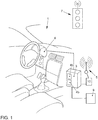
- a vehicle with an exemplary embodiment of the traffic light assistance system according to the invention is explained.
- the vehicle 1 comprises a display device 6 which, in the case shown, is integrated in the combination instrument 6.
- a control device 3 is coupled to this in terms of data technology. Graphics data are generated by the control device 3, transmitted to the output unit 6 and output there.
- the control device 3 comprises a traffic light assistance device 4a and a longitudinal control system 4b.
- the control device 3 is also coupled to a drive unit 9 of the vehicle 1 and can automatically regulate the drive of the vehicle 1 by generating signals and transmitting them to the drive unit 9 so that, for example, the vehicle 1 is accelerated or decelerated.
- control device 3 is coupled to a detection unit 10, which in turn comprises a communication device 5 that can wirelessly communicate with a traffic light 7.
- the acquisition unit 10 can acquire information on the switching times of the traffic light 7 in this way.
- the acquisition unit 10 records information about the vehicle 1, in particular its position relative to the traffic light 7 and its speed v 1 , as well as the distance to a vehicle traveling ahead, provided that such a vehicle is in front of the vehicle 1.
- the vehicle 1 includes an automatic control of the movement of the vehicle 1, the control device 3 generating a display on the display device 6 during an automatic intervention in the control of the vehicle 1, by means of which information about the automatic intervention is output to the driver. For example, a warning message is output if the distance to the vehicle in front is too short and braking is carried out.
- the longitudinal control is automatically regulated, the speed v 1 of the vehicle 1 being regulated.
- the driver of the vehicle 1 is only supported by driving instructions that are displayed by means of the display device 6.
- the control device 3 uses the acquisition unit 10 and its communication device 5 to acquire traffic light phase information from the traffic light 7 and vehicle data of the vehicle 1, in particular the speed v 1 of the vehicle 1 and its position relative to the traffic light 7. Furthermore, vehicles ahead and the distance to them are recorded.
- the control device 3 determines a driving instruction as a function of these data, the traffic light assistance device 4a and the longitudinal control system 4b being integrated as modules in an overall driver assistance system.
- the driving instruction is generated in such a way that the vehicle 1 maintains the safe distance from a vehicle traveling ahead, provided that such a vehicle is detected. Furthermore, the speed v 1 of the vehicle 1 is regulated as a function of the switching times of the traffic light 7 in such a way that the most efficient possible driving behavior is achieved.
- the driving efficiency is calculated using parameters that result from the consequences of the possible driving instructions. In particular, the energy consumption of vehicle 1 is determined, and the travel time to the destination of the route recorded in a navigation system of vehicle 1 is also determined. Furthermore, the vehicle 1 should be controlled in such a way that a uniform flow of traffic is made possible.
- the control device 3 On the basis of the driving instruction generated in this way, the control device 3 generates a signal and transmits it to the drive unit 9, which intervenes accordingly in the drive of the vehicle 1. As a consequence, the vehicle 1 is in particular accelerated or decelerated. Furthermore, the control device 3 generates graphic data and transmits this to the display device 6, where the graphic data are output.
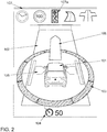
- the display comprises a vehicle symbol 101, which is shown on a virtual roadway 102. There is an arrow 106 in front of the vehicle symbol 101 in the direction of travel.
- the vehicle symbol 101 is surrounded by a warning ring 103, which is divided evenly into eight segments and on which a direction can be indicated from which potential dangers threaten. For example, falling below the safety distance to another vehicle in the vicinity of vehicle 1 can be achieved by highlighting one of the segments of the Warning ring 103 are displayed in order to signal the driver which danger area he must monitor.
- the display also includes a lateral guidance display 105, where arrow symbols can be displayed to the right and left of the vehicle symbol 101 on the virtual lane 102, which can light up when the vehicle 1 approaches the edge of the lane and support the guidance of the vehicle 1 within the lane 2 (please refer Fig. 3 ).
- a display of the setpoint speed 104 In the lower area of the illustration there is a display of the setpoint speed 104.
- the longitudinal control system 4b regulates the speed of the vehicle 1 so that the setpoint speed 104 is reached if this is possible without risk, so as long as z. B. the safety distance to vehicles in front is maintained.
- control objects 107 are shown in the upper area of the display, a traffic light symbol 107a being highlighted in the example shown in order to signal that the traffic light assistance device 4a is active.
- other symbols of rule objects 107 are shown, the associated control being inactive and the symbols therefore being shown "grayed out", i.e. with lower intensity and lower saturation.
- These other symbols of rule objects 107 include, for example, symbols for route guidance and for automated straight-ahead driving.
- the arrow 106 shown is generated in particular as a function of traffic light phase information and vehicle information. This is explained in more detail below.
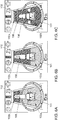
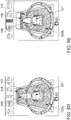
- FIG 3A shows schematically the vehicle 1, which comprises the communication device 5 and is located in the lane 2.
- the vehicle 1 moves at the speed v 1 in the direction of travel F towards the stop line 8.
- the traffic light 7 uses a red light signal to indicate that crossing the stop line 8 is not permitted.
- the vehicle 1 retrieves traffic light phase information from the traffic light 7. Using this information and using vehicle information, such as the speed v 1 of the vehicle 1 and the distance to the stop line 8, it is determined whether the vehicle must stop before the stop line 8 or whether it can drive through without stopping.
- the ones in the Figures 4A and 4B The displays shown can be generated, for example, in order to display acceleration when driving off at a traffic light 7, as in FIG Figure 3D or to indicate a delay as shown in the in Figure 3A situation shown is carried out.
- the representation essentially corresponds to that in Fig. 2 ad already shown.
- the arrow 106 is generated within the scope of the traffic light assistance system according to the invention and adapted to the driving situation.
- the display integrates outputs from the traffic light assistance system and the longitudinal guidance based on the distance from vehicles in front.
- the arrow 106 displayed in front of the vehicle symbol 101 allows measures for controlling the longitudinal guidance of the vehicle 1 to be shown. In particular, changes in speed are shown on the basis of the length of the arrow 106.
- the length of the longitudinal guide arrow 106 is therefore adapted in accordance with the control behavior of the longitudinal control system 4b.
- a longer arrow 106 means that the vehicle 1 is being accelerated, a shorter arrow 106 indicates a deceleration.
- a distinction is also made for the “stop” application in which the vehicle 1 comes to a stop at the end of the braking process.
- the shortest arrow 106 which is also combined with an additional holding line symbol 108, is graphically displayed here.
- the length of the longitudinal guide arrow 106 is thus redundant information for the driver about the Control behavior of the longitudinal control system 4b and is redundant to the perceived driving behavior (for example acceleration of the vehicle 1).
- the Indian Figure 4A The arrow 106 shown in front of the vehicle is longer than the defined initial length as shown in FIG Fig. 2 is shown.
- the arrow 106 extends in Figure 4A almost to the end of the illustrated section of the virtual roadway 102 and therefore signals to the driver of the vehicle 1 that the longitudinal control system 4b is accelerating.
- the arrow 106 shown is shorter than the initial length and thus indicates a delay.
- a particularly short arrow can also signal that the vehicle 1 is being brought to a standstill.
- the display can be generated dynamically, in particular the length of the arrow 106 can change over time or an arrow 106 that is periodically lengthening or shortening can signal the driver that the vehicle 1 is accelerating or decelerating with additional clarity.
- the vehicle symbol 101 is shown on the virtual lane 102.
- the arrow 106 In front of the vehicle symbol 101 is the arrow 106 pointing in the direction of travel.
- a representation has been integrated into the arrow 106 for the longitudinal control, which has the shape of a herringbone pattern and informs the driver of the planned accelerations and decelerations of the longitudinal control system 4b.
- This herringbone pattern depicts three different system states for the distance-based longitudinal control: acceleration, deceleration and deceleration to stop (standstill).
- the herringbone pattern is thus additional information for the driver about the control behavior of the longitudinal control system 4b and is redundant to the perceived driving behavior (e.g. acceleration of vehicle 1).
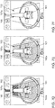
- FIG. 5A An acceleration of the vehicle 1 is displayed, for example in the case shown in FIG Figure 3D illustrated situation of approaching a traffic light 7. This is illustrated by a herringbone pattern pointing forward in the direction of travel on the arrow 106. In the case shown, three arrow elements, which are in the direction of travel from Vehicle symbol 101 pointing away, shown. This signals to the driver of vehicle 1 that he is accelerating in the direction of travel.
- FIG. 5B A deceleration of the vehicle 1 is shown, for example in the case shown in FIG Figure 3A
- three arrow elements are also shown here on the arrow 106 pointing in the direction of travel, but in this case the arrow elements point against the direction of travel to the vehicle symbol 101. This signals a delay to the driver of vehicle 1.
- FIG. 5C The example of a display shown signals a deceleration of the vehicle 1 until it comes to a stop, for example in the in Figure 3C situation of stopping in front of a traffic light shown 7.
- a stop for example in the in Figure 3C situation of stopping in front of a traffic light shown 7.
- three arrow elements pointing against the direction of travel are shown on the arrow 106, as a result of which a delay is signaled to the driver.
- a horizontal line is shown, which is also located on arrow 106. The three arrow elements pointing against the direction of travel point to the horizontal line. This signals to the driver of vehicle 1 that a deceleration is being carried out in such a way that vehicle 1 comes to a standstill.
- the number of arrow elements shown on arrow 106 varies depending on the strength of the acceleration or deceleration of vehicle 1. In particular, more arrow elements are displayed with a greater change in speed than with a smaller change in speed. Furthermore, the size of the arrow elements can be adjusted accordingly. In addition, the arrow elements can be displayed dynamically, for example by the appearance of the arrow elements with a time delay, for example in the manner of a running light that moves towards or away from the vehicle symbol 101. This signals the change in speed to the driver.
- a “color carpet” is integrated in the exemplary embodiments shown, which provides the driver with information on the predicted traffic light phase. It consists of the states “green” and “red”. Is possible also the integration of the "yellow phase”.
- the color carpet is dynamic and behaves analogously to the traffic light phase or the status of the traffic light. With the help of this display, the driver can on the one hand see whether he can reach certain traffic light phases or not, on the other hand he can better prepare for an optimized traffic light start.
- the representation of the color carpet is described in detail below: As a function of the traffic light phase information and the speed v 1 and position of the vehicle 1 relative to the traffic light 7, it is determined whether the traffic light 7 is reached at a point in time at which passage is permitted or not. The consequences of a possible change in speed are also determined.
- the display is generated in such a way that it signals to the driver whether or not he will have to stop at the current speed v 1.
- the virtual roadway 102 is divided into areas that are set off from one another by different colors. This type of display is referred to as a “color carpet”, since the impression of a colored and / or patterned background arises on the virtual roadway 102.
- the color green is shown when the journey can be continued uninterrupted, and the color red when it is necessary to stop.
- This is shown in the drawings by different hatching.
- a yellow-colored area can be displayed which corresponds to a third traffic light phase, in particular a transition phase between the “red” and “green” phases.
- the vehicle 1 can continue its journey at the current speed past the traffic light 7, for example in the mode shown in FIG Figure 3D
- the vehicle symbol 101 is therefore located on the green-colored area 102a of the virtual roadway 102.
- the arrow 106 In front of the vehicle symbol 101 is the arrow 106, on which arrow heads pointing in the direction of travel are shown. Acceleration is thus signaled to the driver of vehicle 1.
- the red-colored area 102b of the virtual roadway 102 is located in front of the vehicle symbol 101. This signals to the driver that excessive acceleration will move the vehicle symbol 101 into the red area and that the journey will not take place without stopping at the Stop line 8 may be continued.
- the display shown signals to the driver that he must brake the vehicle 1 in order to avoid stopping at the traffic light 7, for example in the Figures 3A and 3B illustrated situation of delayed passage at a traffic light 7.
- the vehicle symbol 101 is located in this case at the transition between the red-colored area 102b and the green-colored area 102a of the virtual roadway 102.
- An uninterrupted journey is only possible if the speed v 1 of the vehicle 1 is adjusted so that the vehicle symbol 101 is located on the green marked area 102a of the virtual roadway 102.
- the arrow 106 located in front of the vehicle symbol 101 comprises three arrow heads pointing against the direction of travel to the vehicle symbol 101, which signal the driver of the vehicle 1 that the vehicle 1 is decelerating. This signals a change in speed to the driver, which enables uninterrupted progress in traffic.
- the one in the Figure 6C The display shown is generated when stopping the vehicle at the stop line 8 of the traffic light 7 can no longer be avoided, for example in the in the Figures 3A and 3B
- the area 102b of the virtual roadway 102 on which the vehicle symbol 101 is located is colored red.
- the holding line symbol 108 is located at the end of the arrow 106 in front of the vehicle symbol 101 pointing in the direction of travel Figures 6A and 6B A delay is signaled to the driver in the cases shown.
- the holding line symbol 108 indicates that the vehicle 101 is being brought to a standstill.
- the stopping position is selected in such a way that an optimized start of the vehicle 1 can be carried out.
- the optimized start is described below with reference to the Figures 9A through 9G described in detail.
- the position of the stop line symbol 108 therefore does not represent the position of the actual stop line 8, but rather represents the desired stop position of the vehicle 1 in front of the stop line 8.
- the stop line is only displayed if the vehicle has to stop at a signal that is likely to be red.
- the stop line symbol 108 is not displayed.
- the holding line symbol 108 can also serve the driver as an orientation aid for a possibly optimized stop, as will be explained in more detail below.
- the representation also includes a yellow-marked area of the virtual roadway 102. This represents, in particular, the transition between the red phase and the green phase of the traffic light 7.
- FIG. 7A through 7F a sequence of displays for delayed passage at a traffic light is explained, which of an embodiment of the invention Traffic light assistance system can be generated. This corresponds to the approach of the vehicle speed v 1 to a “green wave”, the traffic lights 7 being configured in such a way that several traffic lights 7 can be passed without stopping at an optimal speed. An example of this situation is in the Figures 3A and 3B shown.
- a traffic light located in front of vehicle 1 in the direction of travel was detected and the traffic light assistance system was activated, recognizable from the highlighted traffic light symbol 107a.
- the vehicle symbol 101 is therefore displayed on the red-colored area 102b of the virtual roadway 102.
- the arrow 106 in the direction of travel in front of the vehicle symbol 101 comprises three arrow elements of a herringbone pattern pointing against the direction of travel, which signal the driver that the vehicle 1 needs to be decelerated.
- the representation of the acceleration or deceleration by a herringbone pattern on the arrow 106 has already been described above.
- the vehicle symbol 101 is located completely in the green-colored area 102a of the virtual roadway 102. This signals to the driver that at the current speed v 1 it is possible to drive through the traffic light 7 without stopping. After the stop line 8 has been traversed, with the vehicle 1 moving freely, as in FIG Figure 7E shown, the entire virtual roadway 102 colored green. This signals that the driver is free to travel. Since the vehicle 1 is not in the vicinity of another traffic light 7, the traffic light assistant becomes inactive and the assigned traffic light symbol 107a is hidden. The virtual roadway 102 is no longer shown highlighted in color, as in FIG Figure 7F shown.
- the one in the Figure 8A The display shown is displayed to the driver of the vehicle 1 if there are no traffic lights 7 in the vicinity in front of the vehicle 1.
- the vehicle symbol 101 is located on the virtual roadway 102, and an arrow 106 located in front of the vehicle and pointing in the direction of travel is shown.
- the traffic light symbol 107a is shown in gray, which signals an inactive traffic light assistance system.
- the in Figure 8B shown display If a traffic light 7 is detected in front of the vehicle 1 at which passage is prohibited and at which a stop of the vehicle 1 is unavoidable, the in Figure 8B shown display.
- the traffic light assistance system is activated and the traffic light symbol 107a is highlighted in color.
- the virtual roadway 102 comprises an area 102b marked in red on which the vehicle symbol 101 is located.
- the arrow 106 displayed in front of the vehicle in the direction of travel comprises three arrow elements pointing against the direction of travel and a horizontal line towards which the arrow elements are directed. This signals to the driver of vehicle 1 that braking must be carried out until vehicle 1 comes to a standstill.
- the displays shown are displayed after the vehicle 1 had to stop at a red traffic light 7.
- the vehicle symbol 101 is located on the virtual roadway 102. Ahead the vehicle symbol 101 is shown the arrow symbol 106, which points away from the vehicle 101 in the direction of travel and ends at the holding line symbol 108.
- a message window 109 opens in the upper area of the display. A message shows the driver how long the red phase will last.
- a counter 110 in FIG Figure 9A The display shown indicates that the traffic light 7 will switch to green in 15 seconds.
- the vehicle symbol 101 is therefore located in the red-colored area 102b of the virtual roadway 102, which signals to the driver that no acceleration should be carried out.
- FIG. 9B the display shows ten seconds later and the display signals that traffic light 7 will switch over in five seconds.
- a green-colored area 102a appears on the virtual roadway 102 behind the vehicle symbol 101, which moves forward in the direction of travel as the waiting time expires and signals to the driver that a start can soon be carried out.
- Figure 9C shows the display shortly before the traffic light 7 switches to green.
- a confirmation request which includes a button 112, is displayed in the message window 109.
- the driver Before the vehicle 101 performs an optimized start, the driver must manually confirm this driving maneuver. In the case shown, this is done by touching the button 112 shown on the display, the touch of which is registered by the driver by means of a touch-sensitive surface of the display device 6.
- the confirmation can be carried out by pressing a button on the center console of the vehicle 1.
- the time until the optimized start is carried out is displayed in the message window 109 by the counter 110, in the illustrated case two seconds.
- the transition from the red-colored area 102b to the green-colored area 102a of the virtual roadway 102 shifts further in the direction of travel towards the stop line 108. This signals to the driver when the vehicle 1 is to be started.
- the optimized start is carried out.
- the corresponding display is in Figure 9E shown.
- the holding line symbol 108 is hidden because the vehicle 1 should no longer be stationary.
- the vehicle symbol 101 is located completely in the green marked area 102a of the virtual roadway 102 and that in front of the vehicle symbol 101
- the arrow 106 shown is opposite to the illustration in FIG Figure 9D extended. This signals to the driver that acceleration is being carried out.
- the in Figure 9F The herringbone pattern shown on the arrow 106 with arrow elements pointing in the direction of travel indicates a further acceleration.
- the vehicle 1 accelerates and drives towards the stop line 8 while the traffic light is still red.
- the movement of the vehicle 1 is controlled in such a way that it crosses the stop line 8 at the moment when the traffic light 7 switches to green and thus enables the journey. There is no longer any traffic light 7 in front of vehicle 1 and the traffic light assistance system becomes inactive, as in FIG Figure 9G represented by the grayed out traffic light symbol 107a.
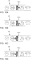
- the Figures 10A to 10D show examples of the symbolic representation of control objects 107, the traffic light assistance system being active for a specific traffic light 7 from a larger number of traffic lights 7.
- the illustration relates to a traffic light 7 which is assigned to a lane to turn off.
- a traffic light symbol 107a is also shown, which in the cases shown comprises an arrow pointing to the right or left.
- the traffic light symbol 107a comprises an arrow pointing to the right, while the arrow in FIG Figure 10B is shown kinking to the right.
- the traffic light symbol 107a includes in FIG Figure 10C a left-pointing arrow that appears in Figure 10D is shown as kinking to the left. This signals to the driver that the display of the traffic light assistance system relates to the traffic light 7 that is assigned to the lane for the respective turning direction.
- the Figures 10E and 10F show representations in which the selection of the lane is indicated by the fact that the vehicle symbol 101 is located on a virtual roadway 102, which in this case is divided into three parts, with a left lane 102l, a straight lane 102g and a right-turn lane 102r being shown.
- the turning lanes to the left 102l and to the right 102r are shown as kinking arrows in the respective direction.
- the vehicle symbol 101 is located in each case on the lane 102l, 102g or 102r on which the real vehicle 1 is also located.
- the color carpet already described above, in which the lane 102 is colored red or green, is used here for each of the individual lanes 102g, 102l and 102r shown. The driver can thus easily see which traffic light phase is to be expected in which lane.
- the vehicle symbol 101 is in the straight lane 102g.
- the vehicle is located in the green-colored area of the lane 102g, as a result of which it is signaled to the driver of the vehicle 1 that he can drive over the traffic light 7 in front of the vehicle in a straight line.
- the vehicle symbol 101 is in the left lane 102l and is here in the red-colored area of the lane 102l. This signals to the driver of the vehicle 1 that the vehicle must be brought to a standstill in front of the stop line 8 at the traffic light 7.
- the two options described above for marking the relevant lane are combined, ie both a traffic light symbol 107a with an arrow in the corresponding direction and several lanes are displayed, the vehicle symbol 101 being on the relevant lane 102g, 102l or 102r is located.
- the number and design of the individual lanes is dependent on the arrangement of the lanes on the real lane 2.
- the display shows the driver driving instructions, which the driver should then actively implement by intervening in the control of the vehicle 1.
- the longitudinal control system 4b is not active or a vehicle 1 does not have such a system.
- the traffic light assistance device 4a generates driving instructions and the control device 3 generates a corresponding display on the display device 6.
Landscapes
- Engineering & Computer Science (AREA)
- General Physics & Mathematics (AREA)
- Physics & Mathematics (AREA)
- Mechanical Engineering (AREA)
- Life Sciences & Earth Sciences (AREA)
- Atmospheric Sciences (AREA)
- Transportation (AREA)
- Automation & Control Theory (AREA)
- Human Computer Interaction (AREA)
- Chemical & Material Sciences (AREA)
- Combustion & Propulsion (AREA)
- Traffic Control Systems (AREA)
- Control Of Driving Devices And Active Controlling Of Vehicle (AREA)
- Lighting Device Outwards From Vehicle And Optical Signal (AREA)
Description
Die Erfindung betrifft ein Ampelassistenzsystem für ein Fahrzeug mit einer Anzeigeeinrichtung für den Fahrer des Fahrzeugs und einer Steuereinrichtung, die ausgebildet ist, in Abhängigkeit von Ampelphaseninformationen und Fahrzeuginformationen zumindest ein Anzeigeelement zu erzeugen.The invention relates to a traffic light assistance system for a vehicle with a display device for the driver of the vehicle and a control device which is designed to generate at least one display element as a function of traffic light phase information and vehicle information.
In modernen Fahrzeugen gewinnen Fahrerassistenzsysteme zur Verbesserung der Sicherheit und des Fahrkomforts stetig an Bedeutung. Unter einem Fahrerassistenzsystem wird eine Einrichtung eines Fahrzeugs verstanden, welche den Fahrer beim Fahren des Fahrzeugs unterstützt. Fahrerassistenzsysteme im Sinne der Erfindung umfassen somit sowohl reine Informationssysteme, welche den Fahrer unterstützen, als auch Einrichtungen, welche automatisch die Fortbewegung des Fahrzeugs beeinflussen, wobei sie die Fahrfunktionen des Fahrzeugs regeln können oder in die Fahrfunktionen eingreifen können.In modern vehicles, driver assistance systems for improving safety and driving comfort are becoming increasingly important. A driver assistance system is understood to mean a device in a vehicle which supports the driver when driving the vehicle. Driver assistance systems within the meaning of the invention thus include both pure information systems that support the driver and devices that automatically influence the movement of the vehicle, whereby they can regulate the driving functions of the vehicle or intervene in the driving functions.
Ohne das Fahrerassistenzsystem beeinflusst der Fahrer direkt die Bewegung des Fahrzeugs. Es werden allenfalls Signale oder Bewegungen von vom Fahrer betätigten Bedienelementen, wie der Pedalerie, dem Schaltknüppel oder dem Lenkrad, an entsprechende Einrichtungen des Fahrzeugs übertragen, welche die Fortbewegung des Fahrzeugs beeinflussen. Eine derartige Fortbewegung des Fahrzeugs entspricht dem geringsten Grad der Automatisierung. Bei einem höheren Grad der Automatisierung wird zum Teil automatisch in Einrichtungen eingegriffen, welche der Fortbewegung des Fahrzeugs dienen. Beispielsweise wird in die Lenkung des Fahrzeugs oder die Beschleunigung in positiver oder negativer Richtung eingegriffen. Bei einem noch höheren Grad der Automatisierung wird soweit in Einrichtungen des Fahrzeugs eingegriffen, dass bestimmte Fortbewegungsarten des Fahrzeugs, z. B. eine Geradeausfahrt, automatisch ausgeführt werden können. Beim höchsten Grad der Automatisierung können etwa Routen eines Navigationssystems im Wesentlichen automatisch gefahren werden.Without the driver assistance system, the driver directly influences the movement of the vehicle. At most, signals or movements from operating elements operated by the driver, such as the pedals, the gear stick or the steering wheel, are transmitted to corresponding devices of the vehicle, which influence the movement of the vehicle. Such locomotion of the vehicle corresponds to the lowest degree of automation. In the case of a higher degree of automation, there is automatic intervention in devices which are used to move the vehicle. For example, there is intervention in the steering of the vehicle or the acceleration in a positive or negative direction. With an even higher degree of automation, interventions in facilities of the vehicle are made to the extent that certain types of locomotion of the vehicle, e.g. B. straight ahead, can be carried out automatically. With the highest degree of automation, routes of a navigation system, for example, can be driven essentially automatically.
Im Zuge der Weiterentwicklung von Fahrerassistenzsystemen wird der Einsatzbereich auf urbane Räume ausgedehnt werden, für die komplexere Verkehrssituationen als beispielsweise auf einer Autobahn typisch sind. Ein wesentliches Element der Verkehrsregelung in urbanen Räumen ist die Lichtsignalanlage (LSA) bzw. umgangssprachlich "Ampel". Im Stadtverkehr ist das Fahren zudem durch dichten Verkehr und häufige Stop-and-Go-Situationen gekennzeichnet, in denen Beschleunigen, Verzögern und Anhalten in rascher Folge durchzuführen sind. Insbesondere hier ist eine Übernahme der Längsregelung durch das heute verfügbare Abstandsregelsystem mit Stop-and-Go-Funktion eine erhebliche Erleichterung. Dabei wird die Bewegung des Fahrzeugs teil- oder vollautomatisch durch Beschleunigen oder Verzögern in Fahrtrichtung so gesteuert, dass insbesondere ein ausreichender Abstand zum vorausfahrenden Fahrzeug eingehalten wird. Ferner wird die Geschwindigkeit den äußeren Bedingungen angepasst, um z. B. Verkehrsvorschriften einzuhalten, den Energieverbrauch des Fahrzeugs zu optimieren oder auf herannahende Hindernisse zu reagieren.In the course of the further development of driver assistance systems, the area of application will be extended to urban areas, for which more complex traffic situations than, for example, on a motorway are typical. An essential element of the traffic regulation in urban areas is the traffic light system (LSA) or colloquially "traffic light". In city traffic, driving is also characterized by heavy traffic and frequent stop-and-go situations in which you accelerate, decelerate and stop in rapid succession are to be carried out. Here in particular, taking over the longitudinal control by the distance control system with stop-and-go function available today is a considerable relief. The movement of the vehicle is controlled partially or fully automatically by accelerating or decelerating in the direction of travel in such a way that, in particular, a sufficient distance from the vehicle in front is maintained. Furthermore, the speed is adapted to the external conditions, e.g. B. to comply with traffic regulations, to optimize the energy consumption of the vehicle or to react to approaching obstacles.
Bekannte Assistenzsysteme zur Längsführung von Fahrzeugen berücksichtigen jedoch noch nicht das Element LSA. Der Fahrer muss daher im Umfeld der LSA häufig korrigierend und durch die unbekannten Zeitpunkte des Signalwechsels auch sehr schnell eingreifen. Dies ist unkomfortabel und macht ein vorausschauendes Fahren hinsichtlich Kraftstoff- und Verkehrseffizienz unmöglich. Durch die Berücksichtigung der Signalzustände und der Kenntnis der (zukünftigen) Schaltzeitpunkte einer LSA kann eine signifikante Verbesserung der Assistenz hinsichtlich Fahrkomfort, Energieverbrauch und Stauminderung erreicht werden. Gleichzeitig müssen Eingriffe des Fahrerassistenzsystem für den Fahrer leicht nachvollziehbar sein, damit dieser das Verhalten seines Fahrzeugs einschätzen kann und - etwa bei einer plötzlichen Änderung der Verkehrssituation - selbst korrigierend eingreifen kann.However, known assistance systems for longitudinal guidance of vehicles do not yet take the LSA element into account. The driver therefore often has to take corrective action in the vicinity of the traffic signal and, due to the unknown times of the signal change, also have to intervene very quickly. This is uncomfortable and makes predictive driving in terms of fuel and traffic efficiency impossible. By taking into account the signal states and knowing the (future) switching times of a traffic light system, a significant improvement in assistance with regard to driving comfort, energy consumption and congestion reduction can be achieved. At the same time, interventions by the driver assistance system must be easily comprehensible for the driver so that he can assess the behavior of his vehicle and - for example in the event of a sudden change in the traffic situation - can take corrective action.
Bisher sind Anzeigevarianten für Ampelsituationen bekannt, die entweder ein Ampelsymbol mit Restzeitanzeige darstellen oder eine Geschwindigkeitsempfehlung anzeigen, durch die eine möglichst gleichmäßige Fahrt gewährleistet werden soll. Nachteilig bei diesen Systemen ist, dass eine Integration der derzeitigen und zukünftigen Signalzustände in Bezug zur Eigenposition des Fahrzeugs in eine Anzeige für Fahrerassistenzsysteme fehlt.So far, display variants for traffic light situations have been known that either display a traffic light symbol with a remaining time display or display a speed recommendation, which is intended to ensure a smooth journey as possible. The disadvantage of these systems is that there is no integration of the current and future signal states in relation to the vehicle's own position in a display for driver assistance systems.
Das Dokument
Der vorliegenden Erfindung liegt die Aufgabe zugrunde, ein Ampelassistenzsystem zur Verfügung zu stellen, dessen Ausgaben der Fahrer schnell und sicher erfassen kann. Erfindungsgemäß wird diese Aufgabe durch ein Ampelassistenzsystem mit den Merkmalen des Anspruchs 1 gelöst. Vorteilhafte Ausgestaltungen und Weiterbildungen ergeben sich aus den abhängigen Ansprüchen.The present invention is based on the object of providing a traffic light assistance system, the outputs of which the driver can record quickly and reliably. According to the invention, this object is achieved by a traffic light assistance system with the features of
Bei dem erfindungsgemäßen Ampelassistenzsystem wird eine Darstellung auf der Anzeigeeinrichtung des Fahrzeugs erzeugt, um Informationen des Ampelassistenzsystems für den Fahrer auszugegeben. Als Referenzpunkt innerhalb der Anzeige dient dabei ein Fahrzeugsymbol, relativ zu dem zumindest ein anderes Anzeigeelement dargestellt wird. Insbesondere wird dieses Anzeigeelement in Abhängigkeit von Informationen über die Ampelphasen und das Fahrzeug erzeugt. Die Ampelphaseninformationen umfassen zum Beispiel insbesondere Daten darüber, zu welchen Zeitpunkten die Ampel schaltet, wann also die Durchfahrt erlaubt oder verboten ist. Anhand der Ampelphaseninformationen kann das Ampelassistenzsystem bestimmen, ob zum gegebenen Zeitpunkt an einer Ampel die Durchfahrt gestattet ist oder in welchen Zeiträumen einzelne Ampeln schalten werden. Die Fahrzeuginformationen können beispielsweise die Position des Fahrzeugs sowie Richtung und Betrag seiner Geschwindigkeit umfassen. Diese Informationen werden insbesondere in Relation zur Ampel erfasst, d.h. es wird etwa der Abstand des Fahrzeugs zur Ampel erfasst. Ferner können die Fahrzeuginformationen Daten zum Beispiel zu einer geplanten Route, zur Verkehrssituation in der Umgebung des Fahrzeugs und auf einer geplanten Route und zu den individuellen Präferenzen des Fahrers umfassen.In the traffic light assistance system according to the invention, a representation is generated on the display device of the vehicle in order to output information from the traffic light assistance system to the driver. A vehicle symbol, relative to which at least one other display element is displayed, serves as a reference point within the display. In particular, this display element is generated as a function of information about the traffic light phases and the vehicle. The traffic light phase information includes, for example, in particular data about the times at which the traffic light switches, that is to say when passage is permitted or prohibited. Using the traffic light phase information, the traffic light assistance system can determine whether passage is permitted at a traffic light at a given point in time or in which time periods individual traffic lights are to be switched. The vehicle information can include, for example, the position of the vehicle and the direction and magnitude of its speed. This information is recorded in relation to the traffic light in particular, i.e. the distance between the vehicle and the traffic light is recorded. Furthermore, the vehicle information can include data, for example, on a planned route, on the traffic situation in the vicinity of the vehicle and on a planned route, and on the individual preferences of the driver.
Aus der Gesamtheit der vom System erfassten Informationen ergeben sich Maßnahmen des Ampelassistenzsystems, also je nach dem Grad der Automatisierung etwa die Ausgabe von Fahrthinweisen für den Fahrer oder die automatische Durchführung eines Beschleunigungs- bzw. Bremsvorgangs, d.h. eine automatische Längsregelung. Dem Fahrer können bei dem erfindungsgemäßen Ampelassistenzsystem in vorteilhafter Weise Ausgaben des Ampelassistenzsystems schnell und sicher erfassbar ausgegeben werden. Diese Ausgaben können im Falle geringer Automatisierung Fahranweisungen sein, die der Fahrer aktiv mittels der Steuerung des Fahrzeugs umsetzen soll. Bei einem höheren Automatisierungsgrad können die Ausgaben Informationen darüber umfassen, welche Fahrmanöver gerade automatisiert ablaufen. Auf diese Weise ist kann gewährleistet werden, dass der Fahrer auch während eines automatischen Eingriffs in die Steuerung des Fahrzeugs stets den Überblick über das Verhalten des Fahrzeugs behält und gegebenenfalls aktiv eingreifen und korrigieren kann.Measures of the traffic light assistance system result from the totality of the information recorded by the system, i.e. depending on the degree of automation, e.g. the output of driving instructions for the driver or the automatic implementation of an acceleration or braking process, i.e. automatic longitudinal control. With the traffic light assistance system according to the invention, outputs of the traffic light assistance system can advantageously be output to the driver in a manner that can be recorded quickly and reliably. In the case of a low level of automation, these outputs can be driving instructions that the driver should actively implement by means of the control of the vehicle. With a higher degree of automation, the outputs can include information about which driving maneuvers are currently running automatically. In this way it can be ensured that the driver always has an overview of the behavior of the vehicle even during an automatic intervention in the control of the vehicle and can, if necessary, actively intervene and correct it.
Dem Fahrer sind damit sowohl die aktuellen als auch die zukünftigen Systemzustände der Assistenzfunktion jederzeit bewusst und er kann infolgedessen Systemvertrauen aufbauen, das heißt, die Maßnahmen des Ampelassistenzsystems sind für den Fahrer nachvollziehbar. Dies führt auch zu einem höheren Befolgungsgrad, d.h. der Fahrer ist bereit, Fahranweisungen des Systems zu befolgen. Durch die Integration der derzeitigen und zukünftigen Signalzustände der Ampel in Bezug zur Eigenposition des Fahrzeugs in eine integrative Anzeige für Fahrerassistenzsysteme, insbesondere für ein Längsregelsystem des Fahrzeugs, können der Fahrkomfort sowie Verbrauchs- und Verkehrseffizienz verbessert werden.The driver is thus aware of both the current and future system states of the assistance function at all times and as a result he can build up system trust, that is, the measures of the traffic light assistance system are comprehensible to the driver. This also leads to a higher degree of compliance, ie the driver is ready to follow the system's driving instructions. By integrating the current and future signal states of the traffic lights in relation to the vehicle's own position in an integrative display for Driver assistance systems, in particular for a longitudinal control system of the vehicle, can improve driving comfort as well as consumption and traffic efficiency.
Unter dem Begriff "Ampel" ist erfindungsgemäß insbesondere eine Lichtsignalanlage zu verstehen, bei der durch Ausgabe eines Lichtsignals Informationen an Verkehrsteilnehmer übermittelt werden. Diese Informationen betreffen beispielsweise die Erlaubnis bzw. das Verbot eine vorgegebene Haltelinie zu überfahren und etwa in eine Kreuzung einzufahren oder geben Vorfahrtsregelungen an einer Kreuzung wieder.According to the invention, the term “traffic light” is to be understood in particular as a light signal system in which information is transmitted to road users by outputting a light signal. This information relates, for example, to the permission or the prohibition to drive over a predetermined stop line and enter an intersection, for example, or reflect right-of-way regulations at an intersection.
Bei dem erfindungsgemäßen Ampelassistenzsystem wird insbesondere eine Anzeige eines Fahrerassistenzsystems erweitert um Anzeigeelemente für die Überquerung einer Ampel mit entsprechender Assistenzfunktion (Ampelassistenz). Die unten beschriebenen Elemente der Anzeige für die Funktion Ampelassistenz können allerdings auch für eine vergleichbare Funktion mit Handlungsempfehlungen oder zur Rückmeldung eines Systemverhaltens genutzt werden. Beispielsweise können andere Verkehrszeichen zum Anhalten auffordern oder die Verkehrsverhältnisse können einen Eingriff eines Fahrerassistenzsystems auslösen. Im Sinne des vorausschauenden Fahrens, bei dem herannahende Gefahrensituationen antizipiert werden, können solche Situationen analog zu einer vor dem Fahrzeug befindlichen Ampel berücksichtigt werden, etwa durch die Anpassung der Geschwindigkeit durch eine automatische Längsregelung oder durch die Ausgabe eines entsprechenden Fahrhinweises für den Fahrer des Fahrzeugs. Informationen zum Zustand des Fahrzeugs und über Eingriffe des Fahrerassistenzsystems können daher auf analoge Weise durch das erfindungsgemäße System ausgegeben werden.In the traffic light assistance system according to the invention, in particular a display of a driver assistance system is expanded to include display elements for crossing a traffic light with a corresponding assistance function (traffic light assistance). The elements of the display described below for the traffic light assistance function can, however, also be used for a comparable function with recommendations for action or for feedback on system behavior. For example, other traffic signs can prompt you to stop or the traffic conditions can trigger an intervention by a driver assistance system. In the sense of anticipatory driving, in which approaching dangerous situations are anticipated, such situations can be taken into account in the same way as a traffic light in front of the vehicle, for example by adjusting the speed using an automatic longitudinal control or by outputting a corresponding driving instruction for the driver of the vehicle. Information about the state of the vehicle and about interventions by the driver assistance system can therefore be output in an analogous manner by the system according to the invention.
Die Ampelassistenzfunktion kann in die bestehende Logik einer bereits bekannten, allgemeinen Anzeige für andere Fahrerassistenzsysteme des Fahrzeugs, etwa eine automatische Längsregelung, integriert werden. Die bereits existierende Längsregelung auf Basis der Abstandsregelung wird in diesem Fall durch das erfindungsgemäße Ampelassistenzsystem zur Unterstützung des Fahrers beim vorausschauenden Durchfahren von Kreuzungen mit Lichtsignalanlagen, einschließlich ggf. Halten und Starten, erweitert. Der Funktionsfokus liegt dabei auf allen mit Lichtsignalanlagen oder vergleichbaren Elementen zur Verkehrsregelung ausgestatteten Streckenabschnitten. Es kann etwa eine aktive und permanente Längsregelung im Rahmen der Abstandsregelung (ACC) erfolgen. Die Unterstützung durch das erfindungsgemäße System fokussiert die assistierte Fahrt und dient insofern als unterstützende und erklärende Information. Allerdings können Elemente aus der mittels des erfindungsgemäßen Systems erzeugten Anzeige auch zur Ausgabe einer Fahrempfehlung ohne eine automatische Längsregelung verwendet werden.The traffic light assistance function can be integrated into the existing logic of an already known, general display for other driver assistance systems of the vehicle, such as automatic longitudinal control. The already existing longitudinal control based on distance control is expanded in this case by the traffic light assistance system according to the invention to support the driver when driving through intersections with traffic lights, including stopping and starting, if necessary. The functional focus is on all route sections equipped with traffic lights or comparable elements for traffic control. For example, an active and permanent longitudinal control can take place within the scope of the distance control (ACC). The support provided by the system according to the invention focuses the assisted drive and in this respect serves as supporting and explanatory information. However, elements from the The display generated according to the invention can also be used to output a driving recommendation without an automatic longitudinal control.
Die Anzeigeeinrichtung ist erfindungsgemäß insbesondere im Kombiinstrument des Fahrzeugs integriert. Der Fahrer kann diesen Bereich besonders leicht überwachen und dort dargestellte Informationen schnell erfassen. Ferner kann es sich bei der Anzeigeeinrichtung beispielsweise um eine Sichtfeldanzeige, etwa ein sogenanntes Head-up-Display, oder einen Bildschirm an der Mittelkonsole des Fahrzeugs handeln.According to the invention, the display device is integrated in particular in the instrument cluster of the vehicle. The driver can monitor this area particularly easily and quickly grasp the information displayed there. Furthermore, the display device can be, for example, a field of view display, for example a so-called head-up display, or a screen on the center console of the vehicle.
Bei einer Weiterbildung des erfindungsgemäßen Ampelassistenzsystems sind die Ampelphaseninformationen über eine Funkschnittstelle empfangbar und/oder aus einer Datenbank lesbar. Das erfindungsgemäße System nutzt vorteilhafterweise insbesondere Informationen über die in der Zukunft liegenden Schaltzeitpunkte der Ampel. Solche Informationen können über geeignete Kommunikationswege, beispielsweise c2X (Car-to-X) oder Mobilfunk, oder in fahrzeuginternen Datenbanken zur Verfügung gestellt werden. Die automatische Kommunikation mit den Ampeln setzt insbesondere das Bestehen eines geeigneten Kommunikationsnetzes voraus, bei dem beispielsweise einzelne Ampelanlagen Informationen zu den Schaltzeiten übertragen oder die Informationen aus anderen Quellen bezogen werden. Es wird erwartet, dass solche Kommunikationsnetze in Zukunft verstärkt zur Verfügung stehen werden, um eine verbesserte Regelung des Verkehrt, vor allem innerhalb von Städten, zu erreichen.In a further development of the traffic light assistance system according to the invention, the traffic light phase information can be received via a radio interface and / or read from a database. The system according to the invention advantageously uses, in particular, information about the future switching times of the traffic light. Such information can be made available via suitable communication channels, for example c2X (Car-to-X) or mobile radio, or in vehicle-internal databases. Automatic communication with the traffic lights requires in particular the existence of a suitable communication network in which, for example, individual traffic light systems transmit information about the switching times or the information is obtained from other sources. It is expected that such communication networks will be increasingly available in the future in order to achieve an improved regulation of traffic, especially within cities.
Da in dieser Ausführung die zukünftige Schaltung von vor dem Fahrzeug liegenden Ampeln im Voraus bekannt ist, deckt der Aktionsraum des erfindungsgemäßen Ampelassistenzsystem einen längeren Streckenabschnitt vor der eigentlichen Ampel und der zugeordneten Haltelinie sowie einen kürzeren Bereich dahinter ab. Auf Basis der erkannten Situation wird ein Regime zugeordnet und damit ein geeignetes, vorausschauendes Fahrmanöver ausgewählt. Als "Regime" werden hierbei insbesondere grundlegende Fahrsituationen danach unterschieden, ob ein Anhalten des Fahrzeugs nötig ist oder ob die Fahrt ohne Halt fortgesetzt werden kann. Eine relevante Situationen ist z. B. eine verzögerte Durchfahrt bei zunächst rotem Signal zum individuellen Einordnen in der "grünen Welle". Das Fahrzeug wird in diesem Fall beim Zufahren auf ein Haltesignal so verzögert, dass es die Haltelinie erst erreicht, wenn die Durchfahrt wieder gestattet ist. Beim Weiterfahren kann die Geschwindigkeit des Fahrzeugs so gesteuert werden, dass kein Halten an vorausliegenden Ampeln erforderlich ist, wenn eine solche optimale Geschwindigkeit ("grüne Welle") vorgesehen ist. Eine weitere beispielhafte Situation ist der unvermeidliche Halt bei rotem Signal und ein nachfolgend optimierter Start. Dabei hält das Fahrzeug in einem bestimmten Abstand vor der Haltelinie, um dann etwa bereits vor dem Umschalten des Lichtsignals so zu beschleunigen, dass die Haltelinie direkt nach dem Zeitpunkt des Umschalten überfahren wird.Since in this embodiment the future switching of traffic lights in front of the vehicle is known in advance, the action area of the traffic light assistance system according to the invention covers a longer route section in front of the actual traffic light and the assigned stop line as well as a shorter area behind it. On the basis of the recognized situation, a regime is assigned and a suitable, predictive driving maneuver is selected. As a “regime”, a distinction is made here in particular between basic driving situations according to whether the vehicle needs to be stopped or whether the journey can be continued without stopping. A relevant situation is e.g. B. a delayed passage with initially a red signal for individual classification in the "green wave". In this case, when approaching a stop signal, the vehicle is decelerated so that it does not reach the stop line until passage is permitted again. When driving on, the speed of the vehicle can be controlled in such a way that it is not necessary to stop at traffic lights ahead if such an optimal speed ("green wave") is provided. Another exemplary situation is the unavoidable stop when the signal is red and a subsequent optimized start. It holds Vehicle at a certain distance in front of the stop line in order to accelerate before the light signal is switched so that the stop line is crossed immediately after the time of switchover.
Bei einer weiteren Ausführung ist die Erfassung der IST-Zustandsdaten, das heißt des aktuellen Signals, der Ampel auf Basis einer sensorbasierten (z.B. Kamera) Detektion implementiert. In diesem Fall detektiert ein Sensor des Fahrzeugs den aktuellen Schaltzustand einer Ampel, etwa an einer vor dem Fahrzeug liegenden Kreuzung, und führt eine Assistenzfunktion anhand dieser Daten durch, etwa durch Anzeige einer Warnmeldung oder automatisches Abbremsen und Beschleunigen des Fahrzeugs.In a further embodiment, the acquisition of the actual status data, i.e. the current signal, of the traffic light is implemented on the basis of a sensor-based (e.g. camera) detection. In this case, a sensor in the vehicle detects the current switching status of a traffic light, for example at an intersection in front of the vehicle, and performs an assistance function based on this data, for example by displaying a warning message or automatically braking and accelerating the vehicle.
Bei einer Weiterbildung der Erfindung umfassen die Fahrzeuginformationen einen Abstand zwischen dem Fahrzeug und der nächsten Ampel in Fahrtrichtung, eine Fahrzeugbeschleunigung und/oder eine Annäherungsgeschwindigkeit des Fahrzeugs an die Ampel. Es werden daher vorteilhafterweise Informationen erfasst, die dem Ampelassistenzsystem erlauben, die Längsführung des Fahrzeugs zu optimieren und die Ausgabe von Warnmeldungen oder automatische Eingriffe, insbesondere eine automatische Längsregelung, durchzuführen.In a further development of the invention, the vehicle information includes a distance between the vehicle and the next traffic light in the direction of travel, a vehicle acceleration and / or a speed of the vehicle approaching the traffic light. Information is therefore advantageously recorded that allows the traffic light assistance system to optimize the longitudinal guidance of the vehicle and to issue warning messages or automatic interventions, in particular automatic longitudinal regulation.
In einer Ausbildung des erfindungsgemäßen Ampelassistenzsystems umfassen die Fahrzeuginformationen Regelparameter eines Längsregelsystems. Diese Regelparameter können insbesondere der Soll-Abstand zu vorausfahrenden Fahrzeugen, eine Änderung der Geschwindigkeit des Fahrzeugs oder andere geplante Eingriffe des Längsregelsystems sein. Das System wird dadurch vorteilhafterweise mit anderen Funktionen und Fahrerassistenzsystemen des Fahrzeugs verknüpft und die Ausgabe kann innerhalb einer Anzeige von Regelparametern für den Fahrer integriert werden. Das Längsregelsystem führt insbesondere die Steuerung der Geschwindigkeit so aus, dass der Sicherheitsabstand zu einem vorausfahrenden Fahrzeug gewahrt wird. Dies wird vom Ampelassistenzsystem berücksichtigt, das heißt beispielsweise, dass Beschleunigungsvorgänge so gestaltet werden, dass der Sicherheitsabstand weiter eingehalten wird. Die Anzeige kann daher sowohl Informationen zur Ampelassistenzfunktion, als auch zur weiteren Längsregelung umfassen.In one embodiment of the traffic light assistance system according to the invention, the vehicle information includes control parameters of a longitudinal control system. These control parameters can in particular be the setpoint distance to vehicles driving ahead, a change in the speed of the vehicle or other planned interventions by the longitudinal control system. The system is thereby advantageously linked with other functions and driver assistance systems of the vehicle and the output can be integrated within a display of control parameters for the driver. In particular, the longitudinal control system controls the speed in such a way that the safety distance to a vehicle in front is maintained. This is taken into account by the traffic light assistance system, which means, for example, that acceleration processes are designed in such a way that the safety distance is maintained. The display can therefore include both information on the traffic light assistance function and on further longitudinal control.
In einer weiteren Ausbildung des erfindungsgemäßen Ampelassistenzsystems sind die Regelparameter in Abhängigkeit von den Ampelphaseninformationen gebildet. Dabei werden die Regelparameter des Längsregelsystems anhand der Informationen gebildet, die das erfindungsgemäße Ampelassistenzsystem erfasst. Dadurch wird der Fahrer in vorteilhafter Weise bei der Steuerung des Fahrzeugs entlastet, insbesondere bei der vorausschauenden Anpassung der Geschwindigkeit an die Verkehrssituation. Insbesondere kann das Ampelassistenzsystem auf diese Weise zur automatischen Steuerung des Fahrzeugs verwendet werden.In a further embodiment of the traffic light assistance system according to the invention, the control parameters are formed as a function of the traffic light phase information. The control parameters of the longitudinal control system are formed on the basis of the information that the traffic light assistance system according to the invention records. This advantageously relieves the driver of the control of the vehicle, in particular of the anticipatory Adaptation of the speed to the traffic situation. In particular, the traffic light assistance system can be used in this way to automatically control the vehicle.
Bei einer Ausgestaltung ist das Längsregelsystem ausgebildet, Regelparameter zur Beschleunigung oder Verzögerung des Fahrzeugs so zu erzeugen, dass die Bewegung des Fahrzeugs vor einer Ampel in Bezug auf die Fahreffizienz optimiert wird. Der Fahrer wird so vorteilhafterweise bei der Führung des Fahrzeugs unterstützt. Der Begriff "Fahreffizienz" fasst erfindungsgemäß verschiedene, teilweise voneinander abhängige Größen zusammen, nach denen die Effizienz der Fahrt beurteilt wird. Zu diesen Größen gehören etwa der Energieverbrauch des Fahrzeugs, die Reisezeit zum Erreichen eines Zielorts und/oder die Eingliederung in den Verkehrsfluss. Abhängig von der Verkehrssituation kann es beispielsweise nötig sein, zur Verkürzung der Reisezeit viele starke Beschleunigungen durchzuführen, was wiederum einen höhere Energieverbrauch des Fahrzeug zur Folge hat. Umgekehrt kann die Reisezeit länger dauern, wenn ein möglichst geringer Energieverbrauch erreicht werden soll. Um ein geeignetes Fahrverhalten zu ermitteln, löst das Längsregelsystem also eine Optimierungsaufgabe, bei der die unterschiedlichen Auswirkungen eines Fahrmanövers analysiert und gewichtet werden. Die Regelparameter werden dann so erzeugt, dass die Fahrt des Fahrzeugs dem Optimum der Fahreffizienz entspricht.In one embodiment, the longitudinal control system is designed to generate control parameters for accelerating or decelerating the vehicle in such a way that the movement of the vehicle in front of a traffic light is optimized with regard to driving efficiency. The driver is thus advantageously supported in driving the vehicle. According to the invention, the term “driving efficiency” encompasses various, partially dependent variables according to which the efficiency of the journey is assessed. These variables include the energy consumption of the vehicle, the travel time to reach a destination and / or the integration into the traffic flow. Depending on the traffic situation, it may be necessary, for example, to accelerate a lot in order to shorten the travel time, which in turn results in higher energy consumption by the vehicle. Conversely, the travel time can be longer if the lowest possible energy consumption is to be achieved. In order to determine suitable driving behavior, the longitudinal control system solves an optimization task in which the different effects of a driving maneuver are analyzed and weighted. The control parameters are then generated in such a way that the journey of the vehicle corresponds to the optimum driving efficiency.
Gemäß der vorliegenden Erfindung ist das Anzeigeelement als Pfeil variabler Länge ausgestaltet und in Fahrtrichtung vor dem Fahrzeugsymbol angeordnet. Durch die Darstellung eines Pfeils als verbreitetem Richtungssymbol wird dem Fahrer vorteilhafterweise schnell erfassbar signalisiert, dass die angezeigten Daten die Bewegung des Fahrzeugs in Fahrtrichtung, also etwa eine Längsregelung betreffen.According to the present invention, the display element is designed as an arrow of variable length and is arranged in the direction of travel in front of the vehicle symbol. By displaying an arrow as a widespread directional symbol, it is advantageously signaled to the driver in a way that can be quickly grasped that the displayed data relate to the movement of the vehicle in the direction of travel, that is, for example, a longitudinal regulation.
Gemäß der vorliegenden Erfindung ist die Länge des Pfeils abhängig von der Beschleunigung oder Verzögerung des Fahrzeugs. Hierdurch wird die Darstellung so erzeugt, dass Informationen über die Änderung der Bewegung des Fahrzeugs in Fahrtrichtung dem Fahrer schnell erfassbar angezeigt werden.According to the present invention, the length of the arrow depends on the acceleration or deceleration of the vehicle. As a result, the display is generated in such a way that information about the change in the movement of the vehicle in the direction of travel is displayed to the driver in a way that can be quickly grasped.
Ferner ist gemäß der vorliegenden Erfindung die Länge des Pfeils abhängig von dem Betrag und/oder der Richtung der Beschleunigung oder Verzögerung des Fahrzeugs. Der Fahrer erkennt dadurch, wie und in welchem Maße die Geschwindigkeit des Fahrzeugs durch den automatischen Eingriff der Längsregelung beeinflusst wird. Dabei kann sowohl das aktuelle Systemverhalten dargestellt werden, das heißt zum Beispiel eine gerade durchgeführte Verzögerung, als auch das für die Zukunft geplante Verhalten, etwa eine bevorstehende Beschleunigung. Insbesondere wird der dargestellte Pfeil länger mit wachsendem Betrag der Beschleunigung in Fahrtrichtung und kürzer mit stärkerer Verzögerung.Furthermore, according to the present invention, the length of the arrow is dependent on the amount and / or the direction of the acceleration or deceleration of the vehicle. This enables the driver to recognize how and to what extent the speed of the vehicle is influenced by the automatic intervention of the longitudinal control. The current system behavior can be displayed, for example a straight line implemented deceleration, as well as the behavior planned for the future, such as an imminent acceleration. In particular, the arrow shown becomes longer as the amount of acceleration in the direction of travel increases and becomes shorter as the deceleration increases.
In einer weiteren Ausführung umfasst der Pfeil ein Fischgrätenmuster, das abhängig davon gestaltet ist, ob ein aktiviertes Längsregelsystem das Fahrzeug beschleunigt, verzögert oder bis zum Stillstand verzögert und/oder ob das Fahrzeug bis zum Erreichen der nächsten Ampel in Fahrtrichtung beschleunigen, verzögern oder bis zum Stillstand vor der Ampel verzögern wird. Durch die Integration einer in anderen Bereichen verbreiteten Symbolik (Fischgrätenmuster) für Beschleunigungs- und Verzögerungsvorgänge auf dem Längsführungspfeil wird dem Fahrer redundante Information über das aktuelle bzw. zukünftige Systemverhalten angezeigt, insbesondere wenn dem Fahrer die Information gleichzeitig an verschiedenen Ausgabeeinheiten im Fahrzeug angezeigt wird. Je nach dem Eingriff des Längsregelsystems in die Fahrt des Fahrzeugs wird die Darstellung des Fischgrätenmusters so angepasst, dass dem Fahrer zusätzliche Informationen dargestellt werden. Dadurch wird die Anzeige in vorteilhafter Weise differenziert, sodass der Fahrer verschiedene Eingriffe des Assistenzsystems unterscheiden und deren Konsequenzen abschätzen kann. Insbesondere können Beschleunigung, Verzögerung und das bevorstehende Anhalten des Fahrzeugs angezeigt werden. Anpassbare Eigenschaften des Fischgrätenmusters können etwa die Anzahl, Dicke und Breite der dargestellten Pfeilelemente sowie die von ihnen angezeigte Richtung sein. Bei einer starken Beschleunigung können beispielsweise viele nach vorne weisende Pfeilelemente angezeigt werden, während eine geringere Zahl von "Gräten" eine geringere Beschleunigung signalisiert.In a further embodiment, the arrow comprises a herringbone pattern, which is designed depending on whether an activated longitudinal control system accelerates, decelerates or decelerates the vehicle to a standstill and / or whether the vehicle accelerates, decelerates or until it reaches the next traffic light in the direction of travel Standstill in front of the traffic lights will delay. By integrating a symbolism (herringbone pattern) for acceleration and deceleration processes on the longitudinal guide arrow, which is widespread in other areas, the driver is shown redundant information about the current or future system behavior, especially if the information is displayed to the driver at different output units in the vehicle at the same time. Depending on the intervention of the longitudinal control system in the movement of the vehicle, the display of the herringbone pattern is adapted so that additional information is displayed to the driver. This differentiates the display in an advantageous manner so that the driver can differentiate between various interventions by the assistance system and assess their consequences. In particular, acceleration, deceleration and the imminent stopping of the vehicle can be displayed. Customizable properties of the herringbone pattern can include the number, thickness, and width of the arrow elements shown and the direction they indicate. In the case of a strong acceleration, for example, many forward-pointing arrow elements can be displayed, while a smaller number of "bones" indicates a lower acceleration.
Ferner können andere Symbole verwendet werden, um die oben beschriebene Funktion des Fischgrätenmusters zu erfüllen. Insbesondere können andere geometrische Formen dargestellt werden, die eine Richtung auszeichnen, etwa Dreiecke oder Pfeilköpfe.Other symbols may also be used to perform the herringbone function described above. In particular, other geometric shapes can be displayed that characterize a direction, such as triangles or arrow heads.
Die Integration nutzerseitig benötigter Informationen zum Verständnis der Längsdynamik, insbesondere der ACC-Regelung, unterstützt den Fahrer dabei zu erkennen, mit welchem Verhalten des Fahrzeugs er rechnen muss und wo er nötigenfalls aktiv einzugreifen muss. Die Anpassung der Länge des Längsführungspfeils entsprechend des Längsregelsystems bietet redundante Information über das aktuelle bzw. zukünftige Systemverhalten, insbesondere wenn dem Fahrer die Information während eines aktuell ausgeführten Eingriffs gleichzeitig an verschiedenen Ausgabeeinheiten im Fahrzeug angezeigt wird und der Fahrer eine aktuell durchgeführte Geschwindigkeitsänderung haptisch wahrnimmt.The integration of information required by the user to understand the longitudinal dynamics, in particular the ACC control, supports the driver in recognizing what behavior of the vehicle he has to expect and where he has to actively intervene if necessary. The adaptation of the length of the longitudinal guide arrow in accordance with the longitudinal control system offers redundant information about the current or future system behavior, in particular if the driver is provided with the information at the same time during an intervention that is currently being carried out different output units in the vehicle is displayed and the driver perceives a current change in speed haptically.
Bei einer Ausgestaltung der Erfindung ist die Steuereinrichtung ausgebildet, mehrere Anzeigeelemente relativ zu dem Fahrzeugsymbol auf der Anzeigeeinrichtung darzustellen, wobei die verschiedenen Anzeigeelemente unterschiedlichen Fahrstreifen und/oder unterschiedlichen Ampeln zugeordnet sind. Dadurch können vorteilhafterweise komplexere Verkehrssituationen umfassend dargestellt werden, wenn beispielsweise mehreren Fahrstreifen jeweils eigene Ampeln zugeordnet sind. Die dargestellte Anzeige setzt eine eindeutige Zuordnung von Fahrzeug und Signalgruppe, etwa eine Ampel, voraus. Ferner können etwa Fahrhinweise für verschieden stark befahrene Fahrstreifen dargestellt werden, auf denen unterschiedliche Eingriffe des Fahrerassistenzsystems notwendig sind, um etwa den Sicherheitsabstand zum vorausfahrenden Fahrzeug zu wahren, obwohl auf allen Fahrstreifen die Signale der gleichen Ampel berücksichtigt werden müssen. Umgekehrt können mehrere Ampeln etwa für verschiedene Richtungen vorhanden sein. In diesen Fällen erzeugt die Steuereinrichtung die Darstellung so, dass mehrere Anzeigeelemente das geplante Verhalten des Fahrzeugs in mehreren alternativen Fahrsituationen darstellen. Ferner kann, um diese Zuordnung zu ermöglichen, etwa ein Abbiegepfeil angezeigt werden, der signalisiert, dass sich die Anzeige auf die entsprechende Abbiegespur bezieht.In one embodiment of the invention, the control device is designed to display a plurality of display elements relative to the vehicle symbol on the display device, the different display elements being assigned to different lanes and / or different traffic lights. As a result, more complex traffic situations can advantageously be represented comprehensively if, for example, several traffic lanes are each assigned their own traffic lights. The displayed display assumes a clear assignment of the vehicle and signal group, such as a traffic light. In addition, driving instructions can be displayed for lanes with different levels of traffic, on which different interventions by the driver assistance system are necessary in order to maintain a safe distance from the vehicle in front, although the signals from the same traffic light must be taken into account in all lanes. Conversely, there can be several traffic lights for different directions. In these cases, the control device generates the display in such a way that several display elements show the planned behavior of the vehicle in several alternative driving situations. Furthermore, in order to enable this assignment, for example a turn arrow can be displayed, which signals that the display relates to the corresponding turn lane.
Beispielsweise kann die Darstellung als Graphikelemente mehrere Pfeile nebeneinander umfassen und Fahrhinweise für verschiedene Fahrstreifen anzeigen, beispielsweise einen geplanten Beschleunigungsvorgang auf dem aktuellen Fahrstreifen, dessen Ampel die Fahrt freigibt, und einen Bremsvorgang auf dem Nachbarfahrstreifen, dessen Ampel den Fahrer zum Halten auffordert. Die Anzeige verschiedener Signalgruppen trägt zur effizienten Steuerung des Verkehrsflusses bei und unterstützt den Fahrer bei der Auswahl einer präferierten oder priorisierten Ampel bzw. des Fahrstreifens.For example, the representation as graphic elements can include several arrows next to each other and display driving instructions for different lanes, for example a planned acceleration process on the current lane, whose traffic light enables the journey, and a braking process on the neighboring lane, whose traffic light prompts the driver to stop. The display of different signal groups contributes to the efficient control of the traffic flow and supports the driver in selecting a preferred or prioritized traffic light or lane.
In einer weiteren Ausbildung ist die Steuereinrichtung ausgebildet, ferner ein Halteliniensymbol relativ zu dem Fahrzeugsymbol auf der Anzeigeeinrichtung darzustellen. Dies erfolgt durch die Integration einer Logik zur bedarfsgerechten Anzeige von Haltelinien, d.h. zur Erzeugung einer Darstellung von Haltelinien durch die Steuereinrichtung. Dieses Symbol wird insbesondere in Situationen angezeigt, in denen das Fahrzeug zum Stillstand gebracht werden soll oder vor einer Ampel steht. Es kann in vorteilhafter Weise dem Fahrer eine aktuell durchgeführte oder geplante Bremsung, womöglich bis zum Stillstand des Fahrzeugs, verdeutlichen oder darauf hinweisen, dass nach der Freigabe der Fahrt durch die Ampel eine Beschleunigung nötig sein wird, um die angestrebte Geschwindigkeit des Fahrzeugs zu erreichen. Ferner kann der Abstand der Halteposition des Fahrzeugs von der Haltelinie signalisiert werden. Die Darstellung kann mehrere Haltelinien umfassen, beispielsweise um Fahrhinweise für mehrere Fahrstreifen anzuzeigen.In a further embodiment, the control device is designed to also display a holding line symbol relative to the vehicle symbol on the display device. This takes place through the integration of a logic for the needs-based display of stop lines, ie for the generation of a display of stop lines by the control device. This symbol is displayed in particular in situations in which the vehicle is to be brought to a standstill or is in front of a traffic light. It can advantageously explain to the driver that braking is currently being carried out or planned, possibly until the vehicle comes to a standstill, or it can indicate that acceleration is necessary after the traffic light has enabled driving to reach the target speed of the vehicle. Furthermore, the distance between the stopping position of the vehicle and the stop line can be signaled. The display can include several stop lines, for example to display driving instructions for several lanes.
Eine Weiterbildung der Erfindung umfasst die Kombination einer bedarfsgerechten Anzeige von Haltelinien mit Informationen über verschiedene Phasen der Durchfahrt im Ampelbereich. Die Eigenschaften der angezeigten Haltelinien werden dazu der Position des Fahrzeugs relativ zur Ampel angepasst. Beispielsweise kann farblich unterschieden werden (Farbbalken), ob das Fahrzeug zum Halt gebracht werden muss oder ob die Haltelinie überfahren werden kann.A further development of the invention comprises the combination of a needs-based display of stop lines with information about different phases of the passage in the traffic light area. The properties of the displayed stop lines are adapted to the position of the vehicle relative to the traffic light. For example, it can be differentiated in color (color bar) whether the vehicle has to be brought to a stop or whether the stop line can be crossed.
In einer weiteren Ausführung erzeugt die Steuereinrichtung die Darstellung so, dass verschieden dargestellte und voneinander abgegrenzte Flächen verschiedene Phasen der Durchfahrt im Ampelbereich anzeigen. Dazu werden die Schaltzeitpunkte der Ampel in Bezug zur Eigenposition und zur Geschwindigkeit des Fahrzeugs gesetzt. Insbesondere sind diese Flächen in verschiedenen Farben dargestellt und werden daher im folgenden "Farbteppich" genannt, allerdings kann die Unterscheidung auch durch andere Merkmale, etwa verschiedene Muster erfolgen. Der Farbteppich kann relativ zum Fahrzeugsymbol so angezeigt werden, dass er in der Darstellung einer in Fahrtrichtung verlaufenden Fahrbahn entspricht. Beispielsweise kann durch die Darstellung des vor dem Fahrzeug liegenden Fahrstreifens in roter Farbe angezeigt werden, dass die vor dem Fahrzeug befindliche Ampel ein Haltsignal zeigt und eine Verzögerung erfolgen soll. Umgekehrt kann grüne Farbe signalisieren, dass die Fahrt freigegeben ist und eine Beschleunigung durchgeführt werden soll. Durch die Anzeige kann dem Fahrer signalisiert werden, dass sich das Fahrzeug bei der aktuellen Geschwindigkeit im "grünen" oder im "roten" Bereich befindet, d.h. ob eine unterbrechungsfreie Fahrt durchgeführt werden kann oder ob eine Bremsung bis zum Stillstand des Fahrzeugs nötig ist. Die Kombination beider Merkmale, etwa die Darstellung eines Fahrstreifens mit roten und grünen Bereichen, erlaubt die Darstellung komplexerer Fahranweisungen, um beispielsweise das Fahrzeug beim Zufahren auf eine rote Ampel abzubremsen, ohne dabei zum Halt zu kommen, und die Haltelinie erst nach der Freigabe durch die Ampel zu überfahren.In a further embodiment, the control device generates the display in such a way that differently displayed areas that are delimited from one another display different phases of the passage in the traffic light area. For this purpose, the switching times of the traffic lights are set in relation to the vehicle's own position and speed. In particular, these areas are shown in different colors and are therefore referred to below as the “color carpet”, although the distinction can also be made by other features, such as different patterns. The color carpet can be displayed relative to the vehicle symbol in such a way that it corresponds in the representation to a roadway running in the direction of travel. For example, by displaying the lane in front of the vehicle in red, it can be indicated that the traffic light in front of the vehicle is showing a stop signal and that a delay should take place. Conversely, the green color can indicate that travel is enabled and that acceleration should be carried out. The display can signal to the driver that the vehicle is in the "green" or in the "red" area at the current speed, i.e. whether an uninterrupted journey can be carried out or whether braking until the vehicle comes to a standstill is necessary. The combination of both features, such as the display of a lane with red and green areas, allows more complex driving instructions to be displayed, for example to brake the vehicle when approaching a red traffic light without coming to a stop, and the stop line only after approval by the To run over traffic lights.
In einer Weiterbildung umfasst das Ampelassistenzsystem einen Wartemodus, der aktiviert wird, wenn das Fahrzeug an einer Ampel zum Halten kommt, wobei die Anzeige ein weiteres Element umfasst, das Informationen über den Status des Ampelassistenzsystems anzeigt. Dies kann beispielsweise erfolgen durch die Integration eines Wartemodus mit folgenden Bestandteilen: Eine Anzeige der verbleibenden Wartezeit (Dauer der Rotlichtphase), etwa eine dynamische Darstellung der sich mit der Zeit verringernden Anzahl der Sekunden bis zum Schalten der Ampel (Counter), sowie eine Anforderung einer Fahrerbestätigung (Handlungsaufforderung) für einen effizienten bzw. optimierten Start, wobei insbesondere eine Meldung angezeigt wird, dass das Assistenzsystem einen automatischen Start des Fahrzeugs durchführen kann, wenn der Fahrer diese Intention durch eine Bedienhandlung bestätigt. Ferner kann eine Anzeige der Wartezeit bis zum optimierten Start angezeigt werden, falls der Fahrer bestätigt hat, dass ein optimierter Start durchgeführt werden soll. Zum Durchführen eines optimierten Starts wird das Fahrzeug zunächst in einem bestimmten Abstand vor der Haltelinie zum Stehen gebracht und bereits vor dem Schalten der Ampel wieder beschleunigt, um gleich nach dem Schalten der Ampel die Haltelinie zu überfahren.In one development, the traffic light assistance system includes a waiting mode that is activated when the vehicle comes to a stop at a traffic light, the display including a further element that displays information about the status of the traffic light assistance system. This can be done, for example, by integrating a waiting mode with the following components: A display of the remaining waiting time (duration of the red light phase), for example one Dynamic display of the number of seconds, which decreases over time, until the traffic light (counter) is switched, as well as a request for a driver confirmation (prompt to take action) for an efficient or optimized start, with a message being displayed in particular that the assistance system is automatically starting the Vehicle can perform if the driver confirms this intention by an operator action. Furthermore, a display of the waiting time until the optimized start can be displayed if the driver has confirmed that an optimized start is to be carried out. To carry out an optimized start, the vehicle is first brought to a standstill at a certain distance in front of the stop line and accelerated again before the traffic light is switched in order to cross the stop line immediately after the traffic light is switched.
Die Erfindung wird nun anhand von Ausführungsbeispielen mit Bezug zu den Zeichnungen erläutert.
Figur 1- zeigt ein Fahrzeug mit einem Ausführungsbeispiel des erfindungsgemäßen Ampelassistenzsystems,
Figur 2- zeigt eine Anzeige, die von einem Ausführungsbeispiel des erfindungsgemäßen Ampelassistenzsystems erzeugt wird,
- Figuren 3A bis 3D
- zeigen Beispiele für die Längsregelung bei Annäherung an eine Ampel,
- Figuren 4A und 4B
- zeigen Anzeigen, die von einem Ausführungsbeispiel des erfindungsgemäßen Ampelassistenzsystems bei einer Beschleunigung und Verzögerung des Fahrzeugs erzeugt werden,
- Figuren 5A bis 5C
- zeigen Anzeigen mit einem Fischgrätenmuster, die von einem Ausführungsbeispiel des erfindungsgemäßen Ampelassistenzsystems erzeugt werden,
- Figuren 6A bis 6C
- zeigen Anzeigen mit unterschiedlich gefärbten Bereichen auf der virtuellen Fahrbahn, die von einem Ausführungsbeispiel des erfindungsgemäßen Ampelassistenzsystems erzeugt werden,
- Figuren 7A bis 7F
- zeigen eine Abfolge von Anzeigen zur verzögerten Durchfahrt an einer Ampel, die von einem Ausführungsbeispiel des erfindungsgemäßen Ampelassistenzsystems erzeugt werden,
- Figuren 8A bis 8E
- zeigen eine Abfolge von Anzeigen zum Halt vor einer Ampel, die von einem Ausführungsbeispiel des erfindungsgemäßen Ampelassistenzsystems erzeugt werden,
- Figuren 9A bis 9G
- zeigen eine Abfolge von Anzeigen bei der Durchführung eines optimierten Startvorgangs nach dem Halt an einer Ampel, die von einem Ausführungsbeispiel des erfindungsgemäßen Ampelassistenzsystems erzeugt werden, und
- Figuren 10A bis 10 F
- zeigen Anzeigen zur Zuordnung mehrerer Fahrstreifen und Ampeln, die von einem Ausführungsbeispiel des erfindungsgemäßen Ampelassistenzsystems erzeugt werden.
- Figure 1
- shows a vehicle with an embodiment of the traffic light assistance system according to the invention,
- Figure 2
- shows a display that is generated by an embodiment of the traffic light assistance system according to the invention,
- Figures 3A to 3D
- show examples of longitudinal control when approaching a traffic light,
- Figures 4A and 4B
- show displays that are generated by an exemplary embodiment of the traffic light assistance system according to the invention when the vehicle accelerates and decelerates,
- Figures 5A to 5C
- show displays with a herringbone pattern, which are generated by an embodiment of the traffic light assistance system according to the invention,
- Figures 6A to 6C
- show displays with differently colored areas on the virtual lane, which are generated by an exemplary embodiment of the traffic light assistance system according to the invention,
- Figures 7A to 7F
- show a sequence of displays for delayed passage at a traffic light, which are generated by an embodiment of the traffic light assistance system according to the invention,
- Figures 8A to 8E
- show a sequence of displays for stopping at a traffic light, which are generated by an exemplary embodiment of the traffic light assistance system according to the invention,
- Figures 9A through 9G
- show a sequence of displays during the implementation of an optimized starting process after stopping at a traffic light, which are generated by an exemplary embodiment of the traffic light assistance system according to the invention, and
- Figures 10A to 10F
- show displays for assigning several lanes and traffic lights, which are generated by an exemplary embodiment of the traffic light assistance system according to the invention.
Mit Bezug zu
Das Fahrzeug 1 umfasst eine Anzeigeeinrichtung 6, die im dargestellten Fall im Kombiinstrument 6 integriert ist. Mit diesem ist eine Steuereinrichtung 3 datentechnisch gekoppelt. Durch die Steuereinrichtung 3 werden Graphikdaten erzeugt, an die Ausgabeeinheit 6 übertragen und dort ausgegeben. Die Steuereinrichtung 3 umfasst eine Ampelassistenzeinrichtung 4a und ein Längsregelsystem 4b. Die Steuereinrichtung 3 ist ferner mit einer Antriebseinheit 9 des Fahrzeugs 1 gekoppelt und kann den Antrieb des Fahrzeugs 1 automatisch regeln, indem es Signale erzeugt und an die Antriebseinheit 9 überträgt, sodass beispielsweise eine Beschleunigung oder eine Verzögerung des Fahrzeugs 1 durchgeführt wird.The
Ferner ist die Steuereinrichtung 3 mit einer Erfassungseinheit 10 gekoppelt, die wiederum eine Kommunikationseinrichtung 5 umfasst, die drahtlos mit einer Ampel 7 kommunizieren kann. Insbesondere kann die Erfassungseinheit 10 auf diesem Wege Informationen zu den Schaltzeiten der Ampel 7 erfassen. Ferner erfasst die Erfassungseinheit 10 Informationen zum Fahrzeug 1, insbesondere seine Position relativ zur Ampel 7 und seine Geschwindigkeit v1, sowie den Abstand zu einem vorausfahrenden Fahrzeug, sofern sich ein solches Fahrzeug vor dem Fahrzeug 1 befindet.Furthermore, the
Im dargestellten Fall umfasst das Fahrzeug 1 eine automatische Steuerung der Bewegung des Fahrzeugs 1, wobei die Steuereinrichtung 3 bei einem automatischen Eingriff in die Steuerung des Fahrzeugs 1 eine Anzeige auf der Anzeigeeinrichtung 6 erzeugt, durch die dem Fahrer Informationen über den automatischen Eingriff ausgegeben werden. Beispielsweise wird eine Warnmeldung ausgegeben, wenn der Abstand zum vorausfahrenden Fahrzeug zu gering ist und eine Bremsung ausgeführt wird. Insbesondere wird die Längssteuerung automatisch geregelt, wobei die Geschwindigkeit v1 des Fahrzeugs 1 geregelt wird.In the illustrated case, the
In einer weiteren Ausführung der Erfindung wird der Fahrer des Fahrzeugs 1 lediglich durch Fahrhinweise unterstützt, die mittels der Anzeigeeinrichtung 6 angezeigt werden.In a further embodiment of the invention, the driver of the
Die Steuereinrichtung 3 erfasst mittels der Erfassungseinheit 10 und deren Kommunikationseinrichtung 5 Ampelphaseninformationen der Ampel 7 und Fahrzeugdaten des Fahrzeugs 1, insbesondere die Geschwindigkeit v1 des Fahrzeugs 1 und seine Position relativ zur Ampel 7. Ferner werden vorausfahrende Fahrzeuge und der Abstand zu ihnen erfasst. Die Steuereinrichtung 3 bestimmt in Abhängigkeit von diesen Daten eine Fahranweisung, wobei die Ampelassistenzeinrichtung 4a und das Längsregelsystem 4b als Module in ein gesamtes Fahrerassistenzsystem integriert sind.The
Die Fahranweisung wird so erzeugt, dass das Fahrzeug 1 den Sicherheitsabstand zu einem vorausfahrenden Fahrzeug einhält, sofern ein solches Fahrzeug erfasst wird. Ferner wird die Geschwindigkeit v1 des Fahrzeugs 1 in Abhängigkeit von den Schaltzeiten der Ampel 7 so geregelt, dass ein möglichst effizientes Fahrverhalten erreicht wird. Die Fahreffizienz wird dabei anhand von Parametern berechnet, die sich aus den Konsequenzen der jeweils möglichen Fahranweisungen ergeben. Insbesondere wird der Energieverbrauch des Fahrzeugs 1 bestimmt, ferner wird die Reisezeit bis zum Ziel der in einem Navigationssystem des Fahrzeugs 1 erfassten Route bestimmt. Ferner soll das Fahrzeugs 1 so gesteuert werden, dass ein gleichmäßiger Verkehrsfluss ermöglicht wird.The driving instruction is generated in such a way that the
Anhand der so erzeugten Fahranweisung erzeugt die Steuereinrichtung 3 ein Signal und überträgt es an die Antriebseinheit 9, die einen entsprechenden Eingriff in den Antrieb des Fahrzeugs 1 vornimmt. Das Fahrzeug 1 wird in der Konsequenz insbesondere beschleunigt oder verzögert. Ferner erzeugt die Steuereinrichtung 3 Graphikdaten und überträgt diese an die Anzeigeeinrichtung 6, wo die Graphikdaten ausgegeben werden.On the basis of the driving instruction generated in this way, the
Mit Bezug zu
Die Anzeige umfasst ein Fahrzeugsymbol 101, das auf einer virtuellen Fahrbahn 102 dargestellt wird. In Fahrtrichtung vor dem Fahrzeugsymbol 101 befindet sich ein Pfeil 106. Das Fahrzeugsymbol 101 ist umgeben von einem Warnring 103, der gleichmäßig in acht Segmente geteilt ist und an dem eine Richtung angezeigt werden kann, aus der potenzielle Gefahren drohen. Beispielsweise kann die Unterschreitung des Sicherheitsabstands zu einem weiteren Fahrzeug in der Umgebung des Fahrzeugs 1 durch Hervorheben eines der Segmente des Warnrings 103 angezeigt werden, um dem Fahrer zu signalisieren, welchen Gefahrenbereich er überwachen muss. Ferner umfasst die Darstellung eine Querführungsanzeige 105, wobei rechts und links neben dem Fahrzeugsymbol 101 auf der virtuellen Fahrbahn 102 Pfeilsymbole dargestellt werden können, die etwa bei einer Annäherung des Fahrzeugs 1 an den Fahrstreifenrand aufleuchten können und die Führung des Fahrzeugs 1 innerhalb des Fahrstreifens 2 unterstützen (siehe
Ferner werden im oberen Bereich der Anzeige Regelobjekte 107 dargestellt, wobei im dargestellten Beispiel ein Ampelsymbol 107a hervorgehoben ist, um zu signalisieren, dass die Ampelassistenzeinrichtung 4a aktiv ist. Ferner werden andere Symbole von Regelobjekten 107 dargestellt, wobei die dazugehörige Regelung inaktiv ist und die Symbole daher "ausgegraut", d.h. mit geringerer Intensität und geringerer Sättigung, dargestellt sind. Diese anderen Symbole von Regelobjekten 107 umfassen etwa Symbole zur Routenführung und zur automatisierten Geradeausfahrt.In addition, control objects 107 are shown in the upper area of the display, a
Der dargestellte Pfeil 106 wird insbesondere in Abhängigkeit von Ampelphaseninformationen und Fahrzeuginformationen erzeugt. Dies wird unten näher erläutert.The
Mit Bezug zu den
Bei dem in
Bei dem in
Mit Bezug zu den
Die in den
Die Darstellung entspricht im Wesentlichen der in
Der vor dem Fahrzeugsymbol 101 angezeigte Pfeil 106 erlaubt die Darstellung von Maßnahmen zur Steuerung der Längsführung des Fahrzeugs 1. Insbesondere werden Geschwindigkeitsänderungen anhand der Länge des Pfeils 106 dargestellt. Es erfolgt also eine Anpassung der Länge des Längsführungspfeils 106 gemäß dem Regelverhalten des Längsregelsystems 4b. Ein längerer Pfeil 106 bedeutet dabei, dass das Fahrzeug 1 beschleunigt wird, ein kürzerer Pfeil 106 weist auf eine Verzögerung hin. Im zweiten Fall erfolgt zudem eine Unterscheidung für den Anwendungsfall "Halt", bei dem das Fahrzeug 1 am Ende des Bremsvorgangs zum Stehen kommt. Hier wird graphisch der kürzeste Pfeil 106 angezeigt, der zudem mit einem zusätzlichen Halteliniensymbol 108 kombiniert wird. Die Länge des Längsführungspfeils 106 ist somit eine redundante Information für den Fahrer über das Regelungsverhalten des Längsregelsystems 4b und steht in Redundanz zum wahrgenommenen Fahrverhalten (z.B. Beschleunigung des Fahrzeugs 1).The
Der in der
Der in
Die Anzeige kann dynamisch erzeugt werden, insbesondere kann sich die Länge des Pfeils 106 über die Zeit ändern oder ein sich periodisch verlängernder oder verkürzender Pfeil 106 kann dem Fahrer eine Beschleunigung bzw. eine Verzögerung des Fahrzeugs 1 mit zusätzlicher Deutlichkeit signalisieren.The display can be generated dynamically, in particular the length of the
Mit Bezug zu den
Wie bereits oben beschrieben, wird das Fahrzeugsymbol 101 auf der virtuellen Fahrspur 102 dargestellt. Vor dem Fahrzeugsymbol 101 befindet sich der in Fahrtrichtung weisende Pfeil 106. In den Pfeil 106 für die Längsregelung wurde eine Darstellung integriert, welche die Form eines Fischgrätenmusters hat und den Fahrer über die geplanten Beschleunigungen und Verzögerungen des Längsregelsystems 4b informiert. Dieses Fischgrätenmuster bildet drei unterschiedliche Systemzustände für die abstandsbasierte Längsregelung ab: Beschleunigung, Verzögerung und Verzögerung auf Halt (Stillstand). Das Fischgrätenmuster ist somit eine zusätzliche Information für den Fahrer über das Regelungsverhalten des Längsregelsystems 4b und steht in Redundanz zum wahrgenommenen Fahrverhalten (z.B. Beschleunigung des Fahrzeugs 1).As already described above, the
Bei dem in
Bei dem in
Das in
In einem weiteren Ausführungsbeispiel variiert die Zahl der auf dem Pfeil 106 dargestellten Pfeilelemente je nach der Stärke der Beschleunigung bzw. der Verzögerung des Fahrzeugs 1. Insbesondere werden bei einer stärkeren Geschwindigkeitsänderung mehr Pfeilelemente angezeigt als bei einer geringeren Geschwindigkeitsänderung. Ferner kann die Größe der Pfeilelemente entsprechend angepasst werden. Zudem kann die Anzeige der Pfeilelemente dynamisch erfolgen, beispielsweise durch Erscheinen der Pfeilelemente mit zeitlicher Verzögerung, etwa nach Art eines Lauflichts, das sich auf das Fahrzeugsymbnol 101 zu oder von ihm weg bewegt. Dem Fahrer wird dadurch die Geschwindigkeitsänderung signalisiert.In a further exemplary embodiment, the number of arrow elements shown on
Mit Bezug zu den
Für die Abbildung der Ampelassistenz in der Anzeige ist in den gezeigten Ausführungsbeispielen ein "Farbteppich" integriert, der dem Fahrer Informationen zur prognostizierten Ampelphase gibt. Er besteht aus den Zuständen "grün" und "rot". Möglich ist ferner die Integration der "Gelbphase". Der Farbteppich ist dynamisch und verhält sich analog zur Ampelphase bzw. dem Status der Ampel. Mit Hilfe dieser Darstellung kann der Fahrer zum einen sehen, ob er bestimmte Ampelphasen erreichen kann oder nicht, zum anderen kann er sich auf einen optimierten Ampelstart besser vorbereiten. Die Darstellung des Farbteppich ist nachfolgend im Detail beschrieben:
In Abhängigkeit von den Ampelphaseninformationen und der Geschwindigkeit v1 und Position des Fahrzeugs 1 relativ zur Ampel 7 wird bestimmt, ob die Ampel 7 zu einem Zeitpunkt erreicht wird, zu dem eine Durchfahrt erlaubt ist oder nicht. Ferner werden die Konsequenzen einer möglichen Geschwindigkeitsänderung bestimmt. Die Anzeige wird so erzeugt, dass dem Fahrer signalisiert wird, ob er bei der aktuellen Geschwindigkeit v1 anhalten müssen wird oder nicht. Dazu wird die virtuelle Fahrbahn 102 in Bereiche aufgeteilt, die durch verschiedene Farben voneinander abgesetzt sind. Diese Art der Anzeige wird als "Farbteppich" bezeichnet, da der Eindruck eines farblich gestalteten und/oder gemusterten Untergrundes auf der virtuellen Fahrbahn 102 entsteht.For the mapping of the traffic light assistance in the display, a “color carpet” is integrated in the exemplary embodiments shown, which provides the driver with information on the predicted traffic light phase. It consists of the states "green" and "red". Is possible also the integration of the "yellow phase". The color carpet is dynamic and behaves analogously to the traffic light phase or the status of the traffic light. With the help of this display, the driver can on the one hand see whether he can reach certain traffic light phases or not, on the other hand he can better prepare for an optimized traffic light start. The representation of the color carpet is described in detail below:
As a function of the traffic light phase information and the speed v 1 and position of the
Insbesondere wird die Farbe Grün dargestellt, wenn die Fahrt ununterbrochen fortgesetzt werden kann, und die Farbe Rot, wenn ein Anhalten erforderlich ist. Dies ist in den Zeichnungen durch verschiedene Schraffuren dargestellt. Ferner kann ein gelb gefärbter Bereich dargestellt werden, welcher einer dritten Ampelphase entspricht, insbesondere einer Übergangsphase zwischen den Phasen "Rot" und "Grün".In particular, the color green is shown when the journey can be continued uninterrupted, and the color red when it is necessary to stop. This is shown in the drawings by different hatching. Furthermore, a yellow-colored area can be displayed which corresponds to a third traffic light phase, in particular a transition phase between the “red” and “green” phases.
Bei dem in der
Bei der in
Die in der
Die Haltelinie wird erfindungsgemäß nur angezeigt, wenn das Fahrzeug an einem voraussichtlich roten Signal anhalten muss. Bei Erreichen der Haltelinie 8 bei grünem Signal wird das Halteliniensymbol 108 nicht angezeigt. Das Halteliniensymbol 108 kann dem Fahrer darüber hinaus als Orientierungshilfe für einen möglicherweise optimierten Halt dienen, wie weiter unten näher ausgeführt ist.According to the invention, the stop line is only displayed if the vehicle has to stop at a signal that is likely to be red. When the
In einer weiteren Ausführung umfasst die Darstellung ferner einen gelb markierten Bereich der virtuellen Fahrbahn 102. Diese stellt insbesondere den Übergang zwischen der Rotphase und der Grünphase der Ampel 7 dar.In a further embodiment, the representation also includes a yellow-marked area of the
Mit Bezug zu den
In der in
Beim Übergang zu der in
Bei der in
Mit Bezug zu den
Die in der
Wird eine vor dem Fahrzeug 1 befindliche Ampel 7 detektiert, an der die Durchfahrt verboten ist und an der ein Halt des Fahrzeugs 1 unvermeidlich ist, so wird die in
Bei weiterer Annäherung an die Ampel 7 wird die in
Beim Halt im optimalen Abstand zur Haltelinie 8 wird, wie in
Mit Bezug zu den
Die dargestellten Anzeigen werden angezeigt, nachdem das Fahrzeug 1 an einer roten Ampel 7 anhalten musste. Das Fahrzeugsymbol 101 befindet sich auf der virtuellen Fahrbahn 102. Vor dem Fahrzeugsymbol 101 wird das Pfeilsymbol 106 angezeigt, das in Fahrtrichtung vom Fahrzeug 101 wegweist und an dem Halteliniensymbol 108 endet. Im oberen Bereich der Anzeige öffnet sich ein Meldungsfenster 109. Eine Meldung zeigt dem Fahrer an, wie lange die Rotphase noch andauern wird. Insbesondere zeigt ein Zähler 110 bei der in
Nachdem der Fahrer die Durchführung des optimierten Starts bestätigt hat, wird, wie in
Nach Ablauf der Wartezeit wird der optimierte Start durchgeführt. Die entsprechende Anzeige ist in
Durch das in
Die Bewegung des Fahrzeugs 1 wird so gesteuert, dass es die Haltelinie 8 in dem Moment überfährt, in dem die Ampel 7 auf Grün schaltet und die Fahrt damit freigibt. Damit befindet sich vor dem Fahrzeug 1 keine Ampel 7 mehr und das Ampelassistenzsystem wird inaktiv, wie in
Mit Bezug zu den
Die
Die
In der in
In der in
In einem weiteren Ausführungsbeispiel sind die beiden oben beschriebenen Möglichkeiten zur Markierung der relevanten Fahrspur kombiniert, d.h. es wird sowohl ein Ampelsymbol 107a mit einem Pfeil in die entsprechende Richtung angezeigt als auch mehrere Fahrspuren, wobei sich das Fahrzeugsymbol 101 auf der jeweils relevanten Fahrspur 102g, 102l oder 102r befindet. Die Zahl und Gestaltung der einzelnen Fahrstreifen ist dabei abhängig von der Anordnung der Fahrstreifen auf der realen Fahrbahn 2.In a further exemplary embodiment, the two options described above for marking the relevant lane are combined, ie both a
In einem weiteren Ausführungsbeispiel zeigt die Anzeige dem Fahrer Fahranweisungen an, die dieser dann aktiv durch Eingriffe in die Steuerung des Fahrzeugs 1 umsetzen soll. Dies ist insbesondere dann der Fall, wenn das Längsregelsystem 4b nicht aktiv ist oder ein Fahrzeug 1 nicht über ein solches System verfügt. Die Ampelassistenzeinrichtung 4a erzeugt in diesem Fall eine Fahranweisung und die Steuereinrichtung 3 erzeugt eine entsprechende Anzeige auf der Anzeigeeinrichtung 6.In a further exemplary embodiment, the display shows the driver driving instructions, which the driver should then actively implement by intervening in the control of the
- 11
- Fahrzeugvehicle
- 22
- FahrstreifenLane
- 33
- SteuereinrichtungControl device
- 4a4a
- AmpelassistenzeinrichtungTraffic light assistance device
- 4b4b
- LängsregelsystemLongitudinal control system
- 55
- Funkschnittstelle; KommunikationseinrichtungRadio interface; Communication facility
- 66th
- Anzeigeeinrichtung; KombiinstrumentDisplay device; Instrument cluster
- 77th
- Ampeltraffic light
- 88th
- HaltelinieStop line
- 99
- AntriebseinheitDrive unit
- 1010
- ErfassungseinheitRegistration unit
- 101101
- FahrzeugsymbolVehicle symbol
- 102102
- Fahrbahn (Symbol)Lane (symbol)
- 102a102a
- grün markierte Fahrbahn (Symbol)green marked lane (symbol)
- 102b102b
- rot markierte Fahrbahn (Symbol)red marked lane (symbol)
- 102g102g
- Fahrspur geradeausLane straight ahead
- 102l102l
- Fahrspur linksLeft lane
- 102r102r
- Fahrspur rechtsRight lane
- 103103
- WarnringWarning ring
- 104104
- Soll-GeschwindigkeitTarget speed
- 105105
- QuerführungsanzeigeLateral guidance display
- 106106
- Anzeigeelement; PfeilDisplay element; arrow
- 107107
- RegelobjekteRule objects
- 107a107a
- AmpelsymbolTraffic light symbol
- 108108
- HalteliniensymbolHolding line symbol
- 109109
- MeldungsfensterMessage window
- 110110
- Zählercounter
- 112112
- Schaltflächebutton
- FF.
- FahrtrichtungDirection of travel
- DD.
- Abstanddistance
- V1V1
- Geschwindigkeitspeed
Claims (8)
- Traffic light assistance system for a vehicle (1) having a display device (6) for the driver of the vehicle (1) and a control device (3), the latter being embodied for generating at least one display element (106) in dependence on traffic light phase information and vehicle information and for presenting the display element (106) relative to a vehicle symbol (101) on the display device (6), wherein the control device (3) is embodied to generate a corresponding display on the display device (6) and wherein the vehicle symbol (101) serves as a reference point within the display, characterized in that the display element (106) takes the form of an arrow (106) of variable length and is arranged in front of the vehicle symbol (101) in the driving direction (F), and in that the length of the arrow (106) is dependent on the magnitude and/or the direction of the acceleration or deceleration of the vehicle (1).
- Traffic light assistance system according to Claim 1, characterized in that the traffic light phase information is receivable via a radio interface (5) and/or is readable from a database.
- Traffic light assistance system according to Claim 1 or 2, characterized in that the vehicle information comprises a distance between the vehicle (1) and the nearest traffic light (7) in the driving direction, a vehicle acceleration and/or an approach speed of the vehicle (1) towards the traffic light (7).
- Traffic light assistance system according to one of Claims 1 to 3, characterized in that the vehicle information comprises regulating parameters of a length regulation system (4b) and the regulating parameters are formed in dependence on the traffic light phase information.
- Traffic light assistance system according to Claim 4, characterized in that the length regulation system (4b) is embodied for generating regulating parameters for the acceleration or deceleration of the vehicle (1) in a manner such that the movement of the vehicle (1) in front of a traffic light (7) is optimized with respect to the driving efficiency.
- Traffic light assistance system according to one of the preceding claims, characterized in that the arrow (106) comprises a herringbone pattern, which is designed depending on whether an activated length regulation system (4b) accelerates or decelerates the vehicle (1) or decelerates it to a stop and/or whether the vehicle (1) will accelerate or decelerate until the nearest traffic light (7) in the driving direction (F) has been reached or will decelerate to a stop in front of the traffic light (7).
- Traffic light assistance system according to one of the preceding claims, characterized in that the control device (3) is embodied for presenting a plurality of display elements (102g; 1021; 102r) relative to the vehicle symbol (101) on the display device (6), wherein the different display elements are assigned to different lanes (2) and/or different traffic lights (7).
- Traffic light assistance system according to one of the preceding claims, characterized in that the control device (3) is embodied for furthermore presenting a stop line symbol (108) relative to the vehicle symbol (101) on the display device (6).
Applications Claiming Priority (2)
| Application Number | Priority Date | Filing Date | Title |
|---|---|---|---|
| DE102014208942 | 2014-05-12 | ||
| DE102015204122.0A DE102015204122A1 (en) | 2014-05-12 | 2015-03-06 | Traffic light assistance system for a vehicle with a display device |
Publications (3)
| Publication Number | Publication Date |
|---|---|
| EP2944532A2 EP2944532A2 (en) | 2015-11-18 |
| EP2944532A3 EP2944532A3 (en) | 2017-04-26 |
| EP2944532B1 true EP2944532B1 (en) | 2021-06-30 |
Family
ID=53008393
Family Applications (1)
| Application Number | Title | Priority Date | Filing Date |
|---|---|---|---|
| EP15165689.9A Active EP2944532B1 (en) | 2014-05-12 | 2015-04-29 | Traffic light assisting system for a vehicle with a display device |
Country Status (2)
| Country | Link |
|---|---|
| EP (1) | EP2944532B1 (en) |
| DE (1) | DE102015204122A1 (en) |
Families Citing this family (35)
| Publication number | Priority date | Publication date | Assignee | Title |
|---|---|---|---|---|
| DE102015207963B4 (en) | 2015-04-29 | 2018-08-02 | Volkswagen Aktiengesellschaft | Procedure and system for action support |
| DE102015221815B3 (en) * | 2015-07-07 | 2016-12-22 | Volkswagen Aktiengesellschaft | Method for controlling and / or regulating a driving style of a motor vehicle |
| DE102015224114A1 (en) * | 2015-12-02 | 2017-06-08 | Bayerische Motoren Werke Aktiengesellschaft | Transmission control device |
| FR3045545A1 (en) * | 2015-12-21 | 2017-06-23 | Peugeot Citroen Automobiles Sa | DRIVER ASSISTING DEVICE |
| US10636302B2 (en) | 2015-12-22 | 2020-04-28 | Koito Manufacturing Co., Ltd. | Vehicle illumination device, vehicle and illumination control system |
| DE102016204096B4 (en) * | 2016-03-11 | 2022-02-17 | Volkswagen Aktiengesellschaft | Method for operating the driver assistance system and driver assistance system |
| DE102016208793A1 (en) * | 2016-05-20 | 2017-11-23 | Zf Friedrichshafen Ag | Traffic light assistant |
| DE102016007012B4 (en) * | 2016-06-09 | 2018-07-19 | Audi Ag | Method for supporting a driver |
| DE102016009238A1 (en) | 2016-07-28 | 2017-02-16 | Daimler Ag | Method for displaying a traffic light in a vehicle |
| DE102016217558A1 (en) | 2016-09-14 | 2018-03-15 | Continental Teves Ag & Co. Ohg | Method for assigning a traffic light to a traffic lane, vehicle and storage medium |
| DE102016011834A1 (en) | 2016-09-24 | 2017-04-13 | Daimler Ag | Method for outputting at least one traffic-relevant information |
| CA3012334A1 (en) * | 2016-12-29 | 2018-07-05 | Demetrius Thompson | Safe driving system generating map points |
| DE102017204592A1 (en) * | 2017-03-20 | 2018-09-20 | Robert Bosch Gmbh | Method and apparatus for indicating an impending maneuver for a highly automated vehicle |
| DE102017208386A1 (en) * | 2017-05-18 | 2018-11-22 | Ford Global Technologies, Llc | Method for assisting controlling a vehicle, assistance system and vehicle |
| DE102017208646A1 (en) * | 2017-05-22 | 2018-11-22 | Audi Ag | Method for operating a motor vehicle and a motor vehicle |
| DE102017221191B4 (en) | 2017-11-27 | 2019-06-13 | Volkswagen Aktiengesellschaft | Method for displaying the course of a safety zone in front of a vehicle or an object with a display unit, device for carrying out the method and motor vehicle and computer program |
| DE102018203353A1 (en) * | 2018-03-07 | 2019-09-12 | Bayerische Motoren Werke Aktiengesellschaft | Control unit and method for operating a driving function on a signaling system |
| DE102018205753A1 (en) | 2018-04-16 | 2019-10-17 | Bayerische Motoren Werke Aktiengesellschaft | Method, device and means of transport for an automated approach of a means of locomotion to a traffic signal system |
| JP7110729B2 (en) | 2018-05-25 | 2022-08-02 | トヨタ自動車株式会社 | AUTOMATED DRIVING SYSTEM AND CONTROL METHOD FOR AUTOMATED DRIVING SYSTEM |
| FR3085146A1 (en) * | 2018-08-24 | 2020-02-28 | Psa Automobiles Sa | METHOD AND DEVICE FOR ASSISTING THE DRIVING OF A VEHICLE DURING A TRAFFIC LIGHT PASSAGE, BY DISPLAYING BEHAVIORAL INFORMATION |
| FR3085147A1 (en) * | 2018-08-24 | 2020-02-28 | Psa Automobiles Sa | ASSISTANCE IN DRIVING A VEHICLE DURING A THREE-COLOR LIGHT PASSAGE, BY DISPLAYING ITS CURRENT AND FUTURE COLORS |
| DE102018123259A1 (en) * | 2018-09-21 | 2020-03-26 | Robert Bosch Gmbh | System and method for determining a signal image of a signal generator of a light signal system |
| DE102018216383B4 (en) * | 2018-09-25 | 2023-12-07 | Audi Ag | Method and control device for operating a head-mounted display device in a motor vehicle |
| CN109484411B (en) * | 2018-10-25 | 2020-07-10 | 衢州学院 | Vehicle driving state detection method based on big data |
| FR3108083B1 (en) * | 2020-03-10 | 2022-09-02 | Psa Automobiles Sa | Automated driving system with driver information device. |
| US20210348932A1 (en) * | 2020-05-08 | 2021-11-11 | George Mason University | Systems and methods for coordinating traffic lights |
| DE102020126671A1 (en) | 2020-10-12 | 2022-04-14 | Bayerische Motoren Werke Aktiengesellschaft | Vehicle guidance system and method for operating a driving function when there is a configuration change |
| DE102020126673A1 (en) * | 2020-10-12 | 2022-04-14 | Bayerische Motoren Werke Aktiengesellschaft | Vehicle guidance system and method for outputting information relating to a signaling unit |
| DE102020126670A1 (en) | 2020-10-12 | 2022-04-14 | Bayerische Motoren Werke Aktiengesellschaft | Vehicle guidance system and method for operating a driving function in different modes |
| DE102020007229A1 (en) | 2020-11-20 | 2022-05-25 | Enno Hilliger | Driver assistance system, for example for time-optimized driving through time-dependent traffic restrictions |
| CN112489460A (en) * | 2020-12-03 | 2021-03-12 | 百度国际科技(深圳)有限公司 | Signal lamp information output method and device |
| DE102021104120A1 (en) | 2021-02-22 | 2022-08-25 | Bayerische Motoren Werke Aktiengesellschaft | Vehicle guidance system and method for operating a driving function at a traffic junction |
| KR102652486B1 (en) * | 2021-09-24 | 2024-03-29 | (주)오토노머스에이투지 | Method for predicting traffic light information by using lidar and server using the same |
| CN115050194A (en) * | 2022-06-10 | 2022-09-13 | 绿波速度(浙江)科技有限公司 | Distributed intelligent LED green wave electronic display system applied to general road |
| DE102022124616A1 (en) * | 2022-09-26 | 2024-03-28 | Bayerische Motoren Werke Aktiengesellschaft | Vehicle guidance device and method for operating a vehicle at a right-of-way point |
Family Cites Families (5)
| Publication number | Priority date | Publication date | Assignee | Title |
|---|---|---|---|---|
| US20080030372A1 (en) * | 2006-08-02 | 2008-02-07 | Guixian Lu | Traffic light prediction system |
| DE102008019461A1 (en) * | 2008-04-18 | 2009-10-22 | Daimler Ag | Device for displaying information in vehicle, has display unit, on which information determined by detection units is represented by spatially coded display elements |
| DE102008020728B4 (en) * | 2008-04-25 | 2011-06-16 | Man Nutzfahrzeuge Aktiengesellschaft | Traffic Sign Assistant system |
| DE102008051385A1 (en) * | 2008-10-11 | 2010-04-15 | Man Nutzfahrzeuge Aktiengesellschaft | Optical display system |
| DE102013003565A1 (en) * | 2013-03-01 | 2013-09-19 | Daimler Ag | Method for automatic in-phase voltage control of vehicle heading for light signal system, involves determining required braking distance to standstill of vehicle at light signal system |
-
2015
- 2015-03-06 DE DE102015204122.0A patent/DE102015204122A1/en not_active Withdrawn
- 2015-04-29 EP EP15165689.9A patent/EP2944532B1/en active Active
Also Published As
| Publication number | Publication date |
|---|---|
| EP2944532A2 (en) | 2015-11-18 |
| DE102015204122A1 (en) | 2015-11-12 |
| EP2944532A3 (en) | 2017-04-26 |
Similar Documents
| Publication | Publication Date | Title |
|---|---|---|
| EP2944532B1 (en) | Traffic light assisting system for a vehicle with a display device | |
| EP2349805B1 (en) | Method for controlling a motor vehicle, and device therefor | |
| EP2881829B1 (en) | Method for automatically controlling a vehicle, device for generating control signals for a vehicle and vehicle | |
| EP2812202B1 (en) | Device for automatically guiding an automobile vehicle, automobile vehicle with such a device and method for operating an automobile vehicle | |
| EP2216197B1 (en) | Method for controlling a driver assist system and driver assist system | |
| EP2771227B1 (en) | Method for guiding a vehicle, and driver assistance system | |
| EP3269579B1 (en) | Method for operating an information system and information system | |
| DE19958520A1 (en) | Speed controller for a motor vehicle | |
| DE102012215060A1 (en) | Method for guiding vehicle, involves detecting parameter of environment of vehicle on basis of sensor, and determining driving corridor and desire point in driving corridor on basis of detected parameter | |
| WO2020078810A1 (en) | Method for visualizing a crossing over a road | |
| EP3180221B1 (en) | Driver assistance system | |
| EP2862156A1 (en) | Formation of an emergency lane | |
| EP3138752B1 (en) | Method and system for assisting a user in planning and implementing the driving of a route with a vehicle | |
| EP2669109B1 (en) | Manoeuvre assistance system | |
| DE102007036417A1 (en) | Distance regulating system operating method for vehicle, involves activating event mode during target loss that occurs within event region, and determining event region for ahead-lying route region | |
| EP3569465A1 (en) | System and method for providing an automation function for a vehicle | |
| DE102021109105A1 (en) | Navigation system and method for displaying a navigation map | |
| WO2019233719A1 (en) | Method and device for assisting a driver in a vehicle | |
| EP3592604A1 (en) | Motor vehicle comprising a lighting module for generating a set of symbols | |
| DE102021203551A1 (en) | Driving intention detection | |
| DE10337842A1 (en) | Arrangement for semi-autonomous support to vehicle parking regulates and/or controls servo arrangement to automatically carry out steering movements or corrections in only defined small angular range | |
| DE102020102328A1 (en) | Method and assistance system for vehicle control and motor vehicle | |
| WO2010045903A1 (en) | Apparatus and method for controlling and/or regulating a vehicle using data on vehicles driving in adjacent lanes | |
| EP3747720B1 (en) | Vehicle guidance system and method for operating a vehicle with a plurality of predetermined manual steering semiautonomous modes and non-manual steering semiautonomous modes | |
| WO2022090081A1 (en) | Device and method for detecting a bypass lane |
Legal Events
| Date | Code | Title | Description |
|---|---|---|---|
| PUAI | Public reference made under article 153(3) epc to a published international application that has entered the european phase |
Free format text: ORIGINAL CODE: 0009012 |
|
| AK | Designated contracting states |
Kind code of ref document: A2 Designated state(s): AL AT BE BG CH CY CZ DE DK EE ES FI FR GB GR HR HU IE IS IT LI LT LU LV MC MK MT NL NO PL PT RO RS SE SI SK SM TR |
|
| AX | Request for extension of the european patent |
Extension state: BA ME |
|
| PUAL | Search report despatched |
Free format text: ORIGINAL CODE: 0009013 |
|
| AK | Designated contracting states |
Kind code of ref document: A3 Designated state(s): AL AT BE BG CH CY CZ DE DK EE ES FI FR GB GR HR HU IE IS IT LI LT LU LV MC MK MT NL NO PL PT RO RS SE SI SK SM TR |
|
| AX | Request for extension of the european patent |
Extension state: BA ME |
|
| RIC1 | Information provided on ipc code assigned before grant |
Ipc: B60K 35/00 20060101ALI20170320BHEP Ipc: B60W 30/17 20120101ALN20170320BHEP Ipc: B60W 50/00 20060101ALI20170320BHEP Ipc: B60W 30/14 20060101ALI20170320BHEP Ipc: G08G 1/0967 20060101ALN20170320BHEP Ipc: B60W 50/14 20120101AFI20170320BHEP |
|
| STAA | Information on the status of an ep patent application or granted ep patent |
Free format text: STATUS: REQUEST FOR EXAMINATION WAS MADE |
|
| 17P | Request for examination filed |
Effective date: 20171026 |
|
| RBV | Designated contracting states (corrected) |
Designated state(s): AL AT BE BG CH CY CZ DE DK EE ES FI FR GB GR HR HU IE IS IT LI LT LU LV MC MK MT NL NO PL PT RO RS SE SI SK SM TR |
|
| GRAP | Despatch of communication of intention to grant a patent |
Free format text: ORIGINAL CODE: EPIDOSNIGR1 |
|
| STAA | Information on the status of an ep patent application or granted ep patent |
Free format text: STATUS: GRANT OF PATENT IS INTENDED |
|
| INTG | Intention to grant announced |
Effective date: 20210416 |
|
| GRAS | Grant fee paid |
Free format text: ORIGINAL CODE: EPIDOSNIGR3 |
|
| GRAA | (expected) grant |
Free format text: ORIGINAL CODE: 0009210 |
|
| STAA | Information on the status of an ep patent application or granted ep patent |
Free format text: STATUS: THE PATENT HAS BEEN GRANTED |
|
| AK | Designated contracting states |
Kind code of ref document: B1 Designated state(s): AL AT BE BG CH CY CZ DE DK EE ES FI FR GB GR HR HU IE IS IT LI LT LU LV MC MK MT NL NO PL PT RO RS SE SI SK SM TR |
|
| REG | Reference to a national code |
Ref country code: CH Ref legal event code: EP |
|
| REG | Reference to a national code |
Ref country code: AT Ref legal event code: REF Ref document number: 1406110 Country of ref document: AT Kind code of ref document: T Effective date: 20210715 |
|
| REG | Reference to a national code |
Ref country code: DE Ref legal event code: R096 Ref document number: 502015014866 Country of ref document: DE |
|
| REG | Reference to a national code |
Ref country code: IE Ref legal event code: FG4D Free format text: LANGUAGE OF EP DOCUMENT: GERMAN |
|
| REG | Reference to a national code |
Ref country code: LT Ref legal event code: MG9D |
|
| PG25 | Lapsed in a contracting state [announced via postgrant information from national office to epo] |
Ref country code: HR Free format text: LAPSE BECAUSE OF FAILURE TO SUBMIT A TRANSLATION OF THE DESCRIPTION OR TO PAY THE FEE WITHIN THE PRESCRIBED TIME-LIMIT Effective date: 20210630 Ref country code: BG Free format text: LAPSE BECAUSE OF FAILURE TO SUBMIT A TRANSLATION OF THE DESCRIPTION OR TO PAY THE FEE WITHIN THE PRESCRIBED TIME-LIMIT Effective date: 20210930 Ref country code: FI Free format text: LAPSE BECAUSE OF FAILURE TO SUBMIT A TRANSLATION OF THE DESCRIPTION OR TO PAY THE FEE WITHIN THE PRESCRIBED TIME-LIMIT Effective date: 20210630 |
|
| REG | Reference to a national code |
Ref country code: NL Ref legal event code: MP Effective date: 20210630 |
|
| PG25 | Lapsed in a contracting state [announced via postgrant information from national office to epo] |
Ref country code: LV Free format text: LAPSE BECAUSE OF FAILURE TO SUBMIT A TRANSLATION OF THE DESCRIPTION OR TO PAY THE FEE WITHIN THE PRESCRIBED TIME-LIMIT Effective date: 20210630 Ref country code: GR Free format text: LAPSE BECAUSE OF FAILURE TO SUBMIT A TRANSLATION OF THE DESCRIPTION OR TO PAY THE FEE WITHIN THE PRESCRIBED TIME-LIMIT Effective date: 20211001 Ref country code: SE Free format text: LAPSE BECAUSE OF FAILURE TO SUBMIT A TRANSLATION OF THE DESCRIPTION OR TO PAY THE FEE WITHIN THE PRESCRIBED TIME-LIMIT Effective date: 20210630 Ref country code: RS Free format text: LAPSE BECAUSE OF FAILURE TO SUBMIT A TRANSLATION OF THE DESCRIPTION OR TO PAY THE FEE WITHIN THE PRESCRIBED TIME-LIMIT Effective date: 20210630 Ref country code: NO Free format text: LAPSE BECAUSE OF FAILURE TO SUBMIT A TRANSLATION OF THE DESCRIPTION OR TO PAY THE FEE WITHIN THE PRESCRIBED TIME-LIMIT Effective date: 20210930 |
|
| PG25 | Lapsed in a contracting state [announced via postgrant information from national office to epo] |
Ref country code: SM Free format text: LAPSE BECAUSE OF FAILURE TO SUBMIT A TRANSLATION OF THE DESCRIPTION OR TO PAY THE FEE WITHIN THE PRESCRIBED TIME-LIMIT Effective date: 20210630 Ref country code: SK Free format text: LAPSE BECAUSE OF FAILURE TO SUBMIT A TRANSLATION OF THE DESCRIPTION OR TO PAY THE FEE WITHIN THE PRESCRIBED TIME-LIMIT Effective date: 20210630 Ref country code: CZ Free format text: LAPSE BECAUSE OF FAILURE TO SUBMIT A TRANSLATION OF THE DESCRIPTION OR TO PAY THE FEE WITHIN THE PRESCRIBED TIME-LIMIT Effective date: 20210630 Ref country code: EE Free format text: LAPSE BECAUSE OF FAILURE TO SUBMIT A TRANSLATION OF THE DESCRIPTION OR TO PAY THE FEE WITHIN THE PRESCRIBED TIME-LIMIT Effective date: 20210630 Ref country code: RO Free format text: LAPSE BECAUSE OF FAILURE TO SUBMIT A TRANSLATION OF THE DESCRIPTION OR TO PAY THE FEE WITHIN THE PRESCRIBED TIME-LIMIT Effective date: 20210630 Ref country code: PT Free format text: LAPSE BECAUSE OF FAILURE TO SUBMIT A TRANSLATION OF THE DESCRIPTION OR TO PAY THE FEE WITHIN THE PRESCRIBED TIME-LIMIT Effective date: 20211102 Ref country code: NL Free format text: LAPSE BECAUSE OF FAILURE TO SUBMIT A TRANSLATION OF THE DESCRIPTION OR TO PAY THE FEE WITHIN THE PRESCRIBED TIME-LIMIT Effective date: 20210630 Ref country code: ES Free format text: LAPSE BECAUSE OF FAILURE TO SUBMIT A TRANSLATION OF THE DESCRIPTION OR TO PAY THE FEE WITHIN THE PRESCRIBED TIME-LIMIT Effective date: 20210630 |
|
| PG25 | Lapsed in a contracting state [announced via postgrant information from national office to epo] |
Ref country code: PL Free format text: LAPSE BECAUSE OF FAILURE TO SUBMIT A TRANSLATION OF THE DESCRIPTION OR TO PAY THE FEE WITHIN THE PRESCRIBED TIME-LIMIT Effective date: 20210630 |
|
| REG | Reference to a national code |
Ref country code: DE Ref legal event code: R097 Ref document number: 502015014866 Country of ref document: DE |
|
| PG25 | Lapsed in a contracting state [announced via postgrant information from national office to epo] |
Ref country code: DK Free format text: LAPSE BECAUSE OF FAILURE TO SUBMIT A TRANSLATION OF THE DESCRIPTION OR TO PAY THE FEE WITHIN THE PRESCRIBED TIME-LIMIT Effective date: 20210630 |
|
| PLBE | No opposition filed within time limit |
Free format text: ORIGINAL CODE: 0009261 |
|
| STAA | Information on the status of an ep patent application or granted ep patent |
Free format text: STATUS: NO OPPOSITION FILED WITHIN TIME LIMIT |
|
| PG25 | Lapsed in a contracting state [announced via postgrant information from national office to epo] |
Ref country code: AL Free format text: LAPSE BECAUSE OF FAILURE TO SUBMIT A TRANSLATION OF THE DESCRIPTION OR TO PAY THE FEE WITHIN THE PRESCRIBED TIME-LIMIT Effective date: 20210630 |
|
| 26N | No opposition filed |
Effective date: 20220331 |
|
| PG25 | Lapsed in a contracting state [announced via postgrant information from national office to epo] |
Ref country code: IT Free format text: LAPSE BECAUSE OF FAILURE TO SUBMIT A TRANSLATION OF THE DESCRIPTION OR TO PAY THE FEE WITHIN THE PRESCRIBED TIME-LIMIT Effective date: 20210630 |
|
| REG | Reference to a national code |
Ref country code: CH Ref legal event code: PL |
|
| REG | Reference to a national code |
Ref country code: BE Ref legal event code: MM Effective date: 20220430 |
|
| PG25 | Lapsed in a contracting state [announced via postgrant information from national office to epo] |
Ref country code: MC Free format text: LAPSE BECAUSE OF FAILURE TO SUBMIT A TRANSLATION OF THE DESCRIPTION OR TO PAY THE FEE WITHIN THE PRESCRIBED TIME-LIMIT Effective date: 20210630 Ref country code: LU Free format text: LAPSE BECAUSE OF NON-PAYMENT OF DUE FEES Effective date: 20220429 Ref country code: LI Free format text: LAPSE BECAUSE OF NON-PAYMENT OF DUE FEES Effective date: 20220430 Ref country code: CH Free format text: LAPSE BECAUSE OF NON-PAYMENT OF DUE FEES Effective date: 20220430 |
|
| PG25 | Lapsed in a contracting state [announced via postgrant information from national office to epo] |
Ref country code: BE Free format text: LAPSE BECAUSE OF NON-PAYMENT OF DUE FEES Effective date: 20220430 |
|
| PG25 | Lapsed in a contracting state [announced via postgrant information from national office to epo] |
Ref country code: LT Free format text: LAPSE BECAUSE OF FAILURE TO SUBMIT A TRANSLATION OF THE DESCRIPTION OR TO PAY THE FEE WITHIN THE PRESCRIBED TIME-LIMIT Effective date: 20210630 Ref country code: IE Free format text: LAPSE BECAUSE OF NON-PAYMENT OF DUE FEES Effective date: 20220429 |
|
| REG | Reference to a national code |
Ref country code: AT Ref legal event code: MM01 Ref document number: 1406110 Country of ref document: AT Kind code of ref document: T Effective date: 20220429 |
|
| P01 | Opt-out of the competence of the unified patent court (upc) registered |
Effective date: 20230523 |
|
| PG25 | Lapsed in a contracting state [announced via postgrant information from national office to epo] |
Ref country code: AT Free format text: LAPSE BECAUSE OF NON-PAYMENT OF DUE FEES Effective date: 20220429 |
|
| PGFP | Annual fee paid to national office [announced via postgrant information from national office to epo] |
Ref country code: FR Payment date: 20230421 Year of fee payment: 9 Ref country code: DE Payment date: 20230430 Year of fee payment: 9 |
|
| PGFP | Annual fee paid to national office [announced via postgrant information from national office to epo] |
Ref country code: GB Payment date: 20230418 Year of fee payment: 9 |
|
| PG25 | Lapsed in a contracting state [announced via postgrant information from national office to epo] |
Ref country code: HU Free format text: LAPSE BECAUSE OF FAILURE TO SUBMIT A TRANSLATION OF THE DESCRIPTION OR TO PAY THE FEE WITHIN THE PRESCRIBED TIME-LIMIT; INVALID AB INITIO Effective date: 20150429 |