EP2944427B1 - Motorgetriebenes befestigungswerkzeug - Google Patents
Motorgetriebenes befestigungswerkzeug Download PDFInfo
- Publication number
- EP2944427B1 EP2944427B1 EP15165775.6A EP15165775A EP2944427B1 EP 2944427 B1 EP2944427 B1 EP 2944427B1 EP 15165775 A EP15165775 A EP 15165775A EP 2944427 B1 EP2944427 B1 EP 2944427B1
- Authority
- EP
- European Patent Office
- Prior art keywords
- striker
- cam
- fastening tool
- motor
- housing
- Prior art date
- Legal status (The legal status is an assumption and is not a legal conclusion. Google has not performed a legal analysis and makes no representation as to the accuracy of the status listed.)
- Active
Links
- 230000005540 biological transmission Effects 0.000 claims description 18
- 230000007423 decrease Effects 0.000 claims description 5
- 238000000034 method Methods 0.000 claims description 3
- 230000007246 mechanism Effects 0.000 description 9
- 238000006073 displacement reaction Methods 0.000 description 8
- 230000001276 controlling effect Effects 0.000 description 2
- 230000013011 mating Effects 0.000 description 2
- 230000006835 compression Effects 0.000 description 1
- 238000007906 compression Methods 0.000 description 1
- 230000003247 decreasing effect Effects 0.000 description 1
- 239000000446 fuel Substances 0.000 description 1
- 230000003116 impacting effect Effects 0.000 description 1
- 239000000203 mixture Substances 0.000 description 1
- 238000004806 packaging method and process Methods 0.000 description 1
- 230000001105 regulatory effect Effects 0.000 description 1
- 230000000717 retained effect Effects 0.000 description 1
Images


Classifications
-
- B—PERFORMING OPERATIONS; TRANSPORTING
- B25—HAND TOOLS; PORTABLE POWER-DRIVEN TOOLS; MANIPULATORS
- B25C—HAND-HELD NAILING OR STAPLING TOOLS; MANUALLY OPERATED PORTABLE STAPLING TOOLS
- B25C5/00—Manually operated portable stapling tools; Hand-held power-operated stapling tools; Staple feeding devices therefor
- B25C5/10—Driving means
- B25C5/15—Driving means operated by electric power
-
- B—PERFORMING OPERATIONS; TRANSPORTING
- B25—HAND TOOLS; PORTABLE POWER-DRIVEN TOOLS; MANIPULATORS
- B25C—HAND-HELD NAILING OR STAPLING TOOLS; MANUALLY OPERATED PORTABLE STAPLING TOOLS
- B25C1/00—Hand-held nailing tools; Nail feeding devices
- B25C1/06—Hand-held nailing tools; Nail feeding devices operated by electric power
-
- B—PERFORMING OPERATIONS; TRANSPORTING
- B25—HAND TOOLS; PORTABLE POWER-DRIVEN TOOLS; MANIPULATORS
- B25D—PERCUSSIVE TOOLS
- B25D11/00—Portable percussive tools with electromotor or other motor drive
- B25D11/06—Means for driving the impulse member
- B25D11/10—Means for driving the impulse member comprising a cam mechanism
- B25D11/102—Means for driving the impulse member comprising a cam mechanism the rotating axis of the cam member being coaxial with the axis of the tool
Definitions
- the present invention relates to motor-driven fastening tools.
- Power fastening tools include various driving mechanisms.
- One fastening tool includes a solenoid actuator that drives a blade which drives a fastener.
- Another fastening tool includes a motor-driven gearbox with an eccentric drive which lifts a plunger against a spring, then releases the plunger, with the spring driving the plunger and attached blade which drives the fastener.
- Another fastening tool includes a motor-driven gearbox that drives a linkage to compress air in a cylinder. The compressed air is then released into a smaller cylinder, driving a blade which drives a fastener.
- Another fastening tool includes a battery to power a device which ignites an air-fuel mixture, from which a rapid expansion within a cylinder drives a plunger and attached blade which drives the fastener.
- US-A-3,924,692 describes a driving tool wherein a spring is loaded by the rotation of one of two cams having mating helical surfaces. Rotating one cam lifts a ram against the action of a spring. Both cams comprise sharp drop-off portions which allow the spring to release to drive the ram.
- a fastening tool comprising: a housing having a fastener outlet; a striker mounted for translation in the housing to drive a fastener from the fastener outlet in an unloaded position; a biasing member cooperating with the striker to urge the striker towards the unloaded position; a motor oriented in the housing; a transmission coupled to the motor to receive a rotary input from the motor and to provide a rotary output; and a cam coupled to the transmission to receive the rotary output, the cam having a cam surface in cooperation with the striker such that rotation of the cam translates the striker to a loaded position and to a release position whereby the biasing member drives the striker to the unloaded position, the cam surface being profiled to require a constant torque from the rotary input during translation of the striker to the loaded position while loading the biasing member, wherein the cam surface is profiled to reduce an input torque from the rotary input at an intermediate position between the loaded position and the unloaded position.
- a detent is formed in the cam at an intermediate position to temporarily reduce the input torque from the rotary input.
- the cam has a cylindrical body with the cam surface formed thereabout.
- a slope of the cam surface generally decreases from the unloaded position to the loaded position.
- the cam comprises a helical rib projecting from the cylindrical body to form the cam surface.
- the fastening tool further comprises a cam follower mounted to the striker for engagement with the helical rib.
- the cam comprises: a first helical rib projecting from the cylindrical body to form a first portion of the cam surface; and a second helical rib projecting from the cylindrical body to form a second portion of the cam surface.
- the first helical rib is offset rotationally from the second helical rib.
- the fastening tool further comprises: a first cam follower mounted to the striker for engagement with the first helical rib; and a second cam follower mounted to the striker and spaced apart from the first cam follower for engagement with the second helical rib at an intermediate position of the striker.
- the striker is mounted for translation along an axis in the housing and the motor is oriented in the housing parallel to the striker axis.
- the transmission is oriented in alignment with the motor.
- the cam is oriented in alignment with the transmission.
- the striker is mounted for translation along an axis in the housing; and the motor is oriented in the housing perpendicular to the striker axis.
- the transmission is oriented in alignment with the motor.
- the cam is oriented in alignment with the transmission.
- a method for fastening comprising: receiving a rotary input by a transmission from a motor oriented in a housing of a fastening tool to provide a rotary output; receiving the rotary output by a cam coupled to the transmission, the cam having a cam surface in coorporation with a striker such that rotating the cam translates the striker to a loaded position, wherein the cam surface is profiled to require a constant torque from the rotary input during translation of the striker to the loaded position, and wherein the cam surface is profiled to reduce an input torque from the rotary input at an intermediate position between the loaded position and the unloaded position; loading a biasing member in corporation with the striker during translation of the striker to the loaded position, the biasing member urging the striker towards a release position; further rotating the cam to translate the striker to a release position wherein the biasing member drives the striker to an unloaded position; driving a fastener from a fastener outlet in the housing by
- a detent is formed in the cam at an intermediate position to temporarily reduce the input torque from the rotary input.
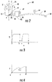
- the fastening tool 20 is illustrated according to an embodiment.
- the fastening tool 20 is depicted as a fastening tool for dispensing staples and brad nails, also known as a tacker.
- various power fastening tools are contemplated.
- the fastening tool 20 is depicted as a handheld power tool.
- the fastening tool 20 has a housing 22 that is formed from a pair of housing portions, of which housing portion 24 is depicted in Figure 1 .
- the housing 22 includes a mating housing portion (not shown) to the housing portion 24 which collectively retain and enclose functional components therein.
- the fastening tool 20 includes a magazine 26, as known in the art, which retains a series or strip of fasteners therein. The fasteners may be adhered together, as is known in the art.
- a fastener outlet 28 is provided in the housing 22 for egress of a fastener from the magazine 26.
- the magazine 26 is spring-loaded to move the fasteners forward after each fastener is driven from the magazine 26.
- a striker 30 is mounted in the housing 22 for linear translation in the housing 22 along an axis 32 through the fastener outlet 28.
- the striker 30 is referred to as a blade due to its shape and, in some embodiments, the blade 30 shears one fastener from the strip of fasteners.
- the blade 30 is connected to a biasing member or power spring 34 provided by a plurality of stacked leaf springs as shown, or as a singular leaf spring that is thicker that the individual springs shown.
- Translation of the blade 30 to a loaded position deforms the power spring 34 thereby loading the power spring 34, such as that depicted in Figure 1 .
- the blade 30 provides clearance in the magazine 26 to translate the strip to present the next sequential fastener in alignment with the fastener outlet 28. Release of the blade 30 causes the power spring 34 to drive the blade 30 to an unloaded position thereby impacting the fastener, and driving the fastener from the fastener outlet 28 and into a workpiece.
- a power source is provided to the fastening tool 20, by an electrical input, which is regulated by a power switch 36.
- the power source may be supplied by a cord that is plugged into an external power supply. Alternatively, the power source may be connected to a battery for a cordless power tool.
- the power source is connected to an electrical motor 38.
- the electrical motor 38 is depicted aligned parallel to, and offset from the striker axis 32.
- the motor 38 provides a rotary input to a transmission or gearbox 40 which reduces an input rotational speed from the motor 38 while increasing an output torque, which is depicted in coaxial alignment.
- a cylindrical cam 42 is coupled to the gearbox 40 and driven by a rotary output of the gearbox 40, which is also depicted in coaxial alignment to the gearbox 40 and the motor 38.
- the cam 42 has a cam surface 44 that is in engagement with a follower 46 on a plunger or carriage 48.
- the carriage 48 is mounted for translation in the housing 22 and supports the blade 30. Rotation of the cam 42 raises the carriage 48, and consequently the blade 30 to the loaded position, and subsequently releases the blade 30. Further rotation of the cam 42 reengages the follower 46 of the carriage 48 and repeats this operation.
- the housing 22 is formed with a handle grip portion 50 for manual gripping of the fastening tool 20.
- An aperture 52 is formed in the housing 22 between the handle grip portion 50 and the magazine 26 for receipt of fingers of a user.
- a manual actuator, such as a trigger 54 extends from the housing 22 into the aperture 52 for manual control.
- the trigger 54 actuates a manual switch 56 that is in electrical communication with a controller or printed circuit board 58 that may be oriented within the handle grip portion 50 for controlling power to the motor 38.
- the drive mechanism 60 includes the power spring 34, which is retained in the housing 22 at a proximal end 62.
- the housing 22 also provides a fulcrum 64 for engaging the power spring 34 during deformation of the power spring 34.
- a distal end 66 of the power spring 34 is engaged with the carriage 48, which is supported for translation in the housing 22 by bearings 68.
- the cam 42 rotates in a direction that is clockwise when viewed in a downward direction in Figure 2 .
- the cam 42 includes a helical rib 70 extending from a cylindrical body 72 of the cam 42 to provide the cam surface 44 to engage the follower 46, which may include a roller bearing or bushing for reducing friction.
- Prior art eccentric drives provide a sinusoidal translation of the plunger. Due to increasing force caused by deformation of a power spring, an output torque required of a motor of a prior art eccentric drive is not linear with a peak torque midway through the cycle. The prior art motor is sized based on the peak torque. Conversely, very little torque is required at the beginning of the cycle. Eccentric drives often release the blade at the loaded position and reengage almost half a rotation from release, resulting in very little work for half the cycle.
- the cam surface 44 includes a slope that decreases as the carriage 48 is raised against the power spring 34. Therefore, as the force required to deform the power spring 34 increases, the slope decreases. The slope of the cam surface 44 is greatest after engagement with the follower 46 at 'a' and steadily decreases until release at position 'd'.
- Figure 3 illustrates a graph of torque ⁇ required by the cam 42 over rotary displacement indicated by ⁇ . After engagement of the follower 46 to the cam surface 44 at point 'a', the torque increases, then remains generally constant due to the decreasing slope of the cam surface 44.
- Figure 4 illustrates the slope of the cam surface 44 depicted in a Cartesian graph of displacement y, or deflection of the power spring 34, over rotary displacement ⁇ .
- the slope can be mathematically derived to allow nearly constant motor torque during lifting operations.
- the cam surface includes a detent 74 to allow the spring 34 to be held partially loaded.
- the detent 74 is illustrated at rotational locations 'b' and 'c' in the graphs of Figures 3 and 4 .
- the controller 58 may begin a subsequent cycle, and stop at the detent 74 until a subsequent manual trigger pull.
- the detent 74 permits the follower 46 to rest thereby avoiding back-driving a resultant torque to the transmission 40 and motor 38.
- the detent 74 may be oriented at an intermediate position wherein the blade 30 is not fully raised, thereby preventing advancement of the sequential fastener. In a failure condition of the fastening tool 20, such as an impact, a fastener is not aligned with the blade 30 to prevent an inadvertent fastener discharge.
- FIG. 5 depicts a fastening tool 124 according to another embodiment.
- the fastening tool has a housing 126 that is formed from a pair of housing portions, of which housing portion 128 is depicted.
- the fastening tool 124 includes a fastener magazine 130.
- a fastener outlet 132 is provided in the housing 126.
- a blade 134 is mounted in the housing 126 for linear translation along an axis 136.
- the blade 134 is connected to a carriage 138, which is also mounted to the housing 126 for translation.
- a power spring 140 is provided by a compression spring. Translation of the carriage 138 to a loaded position deforms the power spring 140 thereby loading the power spring 140.
- a power source such as a battery 141 is provided in the housing.
- a power switch 142 controls a functional condition of the tool 124.
- the battery 141 provides an electrical input that is connected to an electrical motor 144.
- the electrical motor 144 is depicted aligned perpendicular to the blade axis 136.
- the motor 144 provides a rotary input to a gearbox 146 which reduces an input rotation from the motor 144 while increasing an output torque, which is depicted in coaxial alignment.
- a spiral cam 148 is coupled to the gearbox 146 and driven by a rotary output of the gearbox 146, which is also depicted in coaxial alignment to the gearbox 146 and the motor 144.
- the cam 148 has a cam surface 150 that is in engagement with a follower 152 on the carriage 138. Rotation of the cam 148 raises the carriage 138, and consequently the blade 134 to the loaded position, and subsequently releases the blade 134. Further rotation of the cam 148 repeats this operation.
- the housing 126 is formed with a handle grip portion 154 for manual gripping of the fastening tool 124.
- An aperture 156 is formed in the housing 126 between the handle grip portion 154 and the magazine 130 for receipt of fingers of a user.
- a trigger 158 extends from the housing 126 into the aperture 156 for manual control.
- the trigger 158 actuates a manual switch 160 that is in electrical communication with a controller or printed circuit board 162 that may be oriented within the handle grip portion 154 for controlling power to the motor 144.
- Figure 6 illustrates the cam 148, which is configured for torque and displacement similar to the first embodiment. Translation of the blade 134, and loading of the spring 140 occurs between points 'a' and 'd'.
- the cam 148 includes a detent 164 at points 'b' and 'c' for a temporary reduction of torque.
- Figures 7 and 8 illustrate similar torque ⁇ versus displacement ⁇ and deflection y versus displacement ⁇ characteristics to the first embodiment. Orientation of the motor 144 and gearbox 146 horizontally permits different packaging of the fastening tool 124.
Landscapes
- Engineering & Computer Science (AREA)
- Mechanical Engineering (AREA)
- Portable Nailing Machines And Staplers (AREA)
- Details Of Spanners, Wrenches, And Screw Drivers And Accessories (AREA)
Claims (14)
- Befestigungswerkzeug (20; 124), umfassend:ein Gehäuse (22; 126) mit einem Befestigungswerkzeug-Ausgang (28; 132);einen Anschlag (30; 134), der translatorisch im Gehäuse angebracht ist, um ein Befestigungswerkzeug vom Befestigungswerkzeug-Ausgang in eine entlastete Position zu treiben;ein Vorspannelement (34; 140), das mit dem Anschlag zusammenwirkt, um den Anschlag zur entlasteten Position hin zu drücken;einen Motor (38; 144), der im Gehäuse ausgerichtet ist;ein Getriebe (40;146), das am Motor angekoppelt ist, um eine Rotationseingabe vom Motor zum empfangen und eine Rotationsausgabe bereitzustellen; undeine Nocke (42; 148), die mit dem Getriebe gekoppelt ist, um die Rotationsausgabe zu empfangen, wobei die Nocke eine Nockenoberfläche (44; 150) aufweist, die mit dem Anschlag so zusammenwirkt, dass die Rotation der Nocke den Anschlag in eine belastete Position und in eine Freigabeposition verschiebt, wodurch das Vorspannelement den Anschlag in die entlastete Position treibt, wobei die Nockenoberfläche so profiliert ist, dass ein konstantes Drehmoment von der Rotationseingabe während der Verschiebung des Anschlags in die belastete Position erforderlich ist, während das Vorspannelement belastet wird,dadurch gekennzeichnet, dass die Nockenoberfläche dazu profiliert ist, ein Eingangsdrehmoment von der Rotationseingabe an einer Zwischenposition zwischen der belasteten Position und der entlasteten Position zu reduzieren.
- Befestigungswerkzeug (20; 124) nach Anspruch 1, wobei eine Arretierung (74; 164) in der Nocke (42; 148) an einer Zwischenposition (b; c) gebildet wird, um das Eingangsdrehmoment von der Rotationseingabe temporär zu reduzieren.
- Befestigungswerkzeug (20) nach Anspruch 2, wobei die Nocke (42) einen zylindrischen Körper aufweist, wobei die Nockenoberfläche (44) dort herum gebildet wird.
- Befestigungswerkzeug (20) nach Anspruch 3, wobei eine Neigung der Nockenoberfläche (44) von der entlasteten Position zur belasteten Position allgemein abnimmt.
- Befestigungswerkzeug (20) nach einem der Ansprüche 3 und 4, wobei die Nocke (42) eine schraubenförmige Rippe (70) umfasst, die vom zylindrischen Körper (72) vorsteht, um die Nockenoberfläche (44) zu bilden.
- Befestigungswerkzeug (20) nach Anspruch 5, weiterhin umfassend einen Nockenfolger (46), der am Anschlag (30) zwecks Eingriff mit der schraubenförmigen Rippe (70) angebracht ist.
- Befestigungswerkzeug (20) nach einem der Ansprüche 1 bis 6, wobei der Anschlag (30) zur Verschiebung entlang einer Achse (32) im Gehäuse (22) angebracht ist; und
wobei der Motor (38) im Gehäuse parallel zur Anschlagachse ausgerichtet ist. - Befestigungswerkzeug (20) nach Anspruch 7, wobei das Getriebe (40) in Ausrichtung mit dem Motor (38) orientiert ist.
- Befestigungswerkzeug (20) nach Anspruch 8, wobei die Nocke (42) in Ausrichtung mit dem Getriebe (40) orientiert ist.
- Befestigungswerkzeug (124) nach einem der Ansprüche 1 und 2, wobei der Anschlag (134) zur Verschiebung entlang einer Achse (136) im Gehäuse (126) angebracht ist; und
wobei der Motor (144) im Gehäuse senkrecht zur Anschlagachse orientiert ist. - Befestigungswerkzeug (124) nach Anspruch 10, wobei das Getriebe (146) in Ausrichtung mit dem Motor (144) orientiert ist.
- Befestigungswerkzeug (124) nach Anspruch 11, wobei die Nocke (148) in Ausrichtung mit dem Getriebe (146) orientiert ist.
- Befestigungsverfahren, umfassend:Empfangen einer Rotationseingabe durch ein Getriebe (40; 146) von einem Motor (38; 144), der in einem Gehäuse (22; 126) eines Befestigungswerkzeugs (20; 124) orientiert ist, um eine Rotationsausgabe bereitzustellen;Empfangen der Rotationsausgabe durch eine Nocke (42; 148), die am Getriebe angekoppelt ist, wobei die Nocke eine Nockenoberfläche (44; 150) aufweist, die mit einem Anschlag (30; 134) so zusammenwirkt, dass die Rotation der Nocke den Anschlag in eine belastete Position verschiebt, wobei die Nockenoberfläche so profiliert ist, dass ein konstantes Drehmoment von der Rotationseingabe während der Verschiebung des Anschlags in die belastete Position erforderlich ist;Belasten eines Vorspannelements (34; 140) in Zusammenwirken mit dem Anschlag während der Verschiebung des Anschlags in die belastete Position, wobei das Vorspannelement den Anschlag zu einer Freigabeposition hin drückt;weiterhin Rotation der Nocke zur Verschiebung des Anschlags in eine Freigabeposition, wobei das Vorspannelement den Anschlag zu einer entlasteten Position treibt;Antreiben eines Befestigungswerkzeugs von einem Befestigungswerkzeug-Ausgang (28; 132) im Gehäuse durch den Anschlag,dadurch gekennzeichnet, dass die Nockenoberfläche dazu profiliert ist, ein Eingangsdrehmoment von der Rotationseingabe an einer Zwischenposition zwischen der belasteten Position und der entlasteten Position zu reduzieren.
- Verfahren nach Anspruch 13, wobei eine Arretierung (74; 164) in der Nocke (42; 148) an einer Zwischenposition (b; c) gebildet wird, um das Eingangsdrehmoment von der Rotationseingabe temporär zu reduzieren.
Applications Claiming Priority (1)
| Application Number | Priority Date | Filing Date | Title |
|---|---|---|---|
| US14/266,050 US9701001B2 (en) | 2014-04-30 | 2014-04-30 | Motor-driven fastening tool |
Publications (3)
| Publication Number | Publication Date |
|---|---|
| EP2944427A2 EP2944427A2 (de) | 2015-11-18 |
| EP2944427A3 EP2944427A3 (de) | 2016-02-24 |
| EP2944427B1 true EP2944427B1 (de) | 2019-04-17 |
Family
ID=53039303
Family Applications (1)
| Application Number | Title | Priority Date | Filing Date |
|---|---|---|---|
| EP15165775.6A Active EP2944427B1 (de) | 2014-04-30 | 2015-04-29 | Motorgetriebenes befestigungswerkzeug |
Country Status (7)
| Country | Link |
|---|---|
| US (1) | US9701001B2 (de) |
| EP (1) | EP2944427B1 (de) |
| CN (1) | CN105033951B (de) |
| AU (1) | AU2015202109B2 (de) |
| CA (1) | CA2889871C (de) |
| MX (1) | MX356633B (de) |
| TW (1) | TWI703020B (de) |
Families Citing this family (4)
| Publication number | Priority date | Publication date | Assignee | Title |
|---|---|---|---|---|
| US10004503B2 (en) * | 2015-10-16 | 2018-06-26 | Tsung-Wen Huang | Staples push unit for tackers |
| US10814465B2 (en) | 2016-03-22 | 2020-10-27 | Stanley Black & Decker, Inc. | Safety device for tackers |
| WO2019127070A1 (en) * | 2017-12-27 | 2019-07-04 | Powervision Tech Inc. | Driving mechanism of unmanned vessel, releasing structure and feeding device associated with the driving mechanism of unmanned vessel |
| CN115972153B (zh) * | 2023-03-22 | 2023-05-23 | 中铁十七局集团建筑工程有限公司 | 一种电动气压射钉枪 |
Family Cites Families (40)
| Publication number | Priority date | Publication date | Assignee | Title |
|---|---|---|---|---|
| US3042924A (en) | 1959-03-12 | 1962-07-10 | Porter Cable Machine Co | Power nailing machine |
| US3305156A (en) | 1965-02-01 | 1967-02-21 | Khan Joseph Anthony | Fastener machines |
| US3513918A (en) * | 1968-08-15 | 1970-05-26 | Hughes Tool Co | Safety improvements in cam-and-spring operated impact tool |
| US3913685A (en) * | 1974-02-06 | 1975-10-21 | Illinois Tool Works | Fastener driving tool |
| US3924692A (en) | 1974-02-06 | 1975-12-09 | Illinois Tool Works | Fastener driving tool |
| US4082152A (en) * | 1977-01-14 | 1978-04-04 | Hughes Tool Company | Cam mounting for an impact tool |
| US4380312A (en) | 1980-07-17 | 1983-04-19 | Minnesota Mining And Manufacturing Company | Stapling tool |
| DE3239256A1 (de) | 1982-10-23 | 1984-04-26 | Signode Corp., Glenview, Ill. | Heftgeraet |
| DE3427614A1 (de) * | 1984-07-26 | 1986-01-30 | Hilti Ag, Schaan | Eintreibgeraet fuer naegel und dergleichen befestigungselemente |
| US4592502A (en) | 1984-11-05 | 1986-06-03 | Black & Decker Inc. | Offset electric stapler |
| EP0231945A1 (de) | 1986-02-06 | 1987-08-12 | Rodger J. Byrne | Elektroheftgerät |
| JPS62236684A (ja) * | 1986-04-08 | 1987-10-16 | 丸善株式会社 | 電動ステプラ− |
| DE8704666U1 (de) * | 1986-08-02 | 1987-05-21 | Demba Metallwarenfabrik GmbH, 2072 Bargteheide | Elektrisch betriebenes Eintreibgerät |
| US4811885A (en) | 1988-03-23 | 1989-03-14 | Lai Wen Tan | Power transmission mechanism of an electric stapler |
| US4953774A (en) * | 1989-04-26 | 1990-09-04 | Regitar Power Tools Co., Ltd. | Electric stapling gun with auto-reset, energy-saving and shock-absorbing functions |
| DE8907788U1 (de) | 1989-06-26 | 1989-08-31 | Erwin Müller GmbH & Co, 4450 Lingen | Heft- und Nagelgerät mit einem elektrischen Antrieb |
| US4984640A (en) * | 1990-02-26 | 1991-01-15 | Gillan Leland E | Power post driver and hammer |
| AU637367B2 (en) * | 1990-04-24 | 1993-05-27 | Regitar Power Tools Co Ltd | A transmission mechanism for an electric stapling gun |
| GB2260289B (en) | 1991-09-10 | 1994-10-19 | Ofrex Group Holdings Plc | Improvements in or relating to an electrically-powered stapling machine |
| JP2568736Y2 (ja) | 1993-12-06 | 1998-04-15 | マックス株式会社 | 可搬形電動ステープル打機 |
| US5836403A (en) * | 1996-10-31 | 1998-11-17 | Snap-On Technologies, Inc. | Reversible high impact mechanism |
| US5927585A (en) * | 1997-12-17 | 1999-07-27 | Senco Products, Inc. | Electric multiple impact fastener driving tool |
| US5941441A (en) * | 1998-03-10 | 1999-08-24 | Ilagan; Artemio M. | Electric nailing gun |
| AU2001278601A1 (en) * | 2000-08-15 | 2002-02-25 | Fisher Power Wave Limited | Improved cam operated devices |
| US6785950B1 (en) * | 2001-08-31 | 2004-09-07 | Jonard Industries Corp. | Battery-powered wire insertion impact tool |
| US7152774B2 (en) * | 2005-01-03 | 2006-12-26 | Aplus Pneumatic Corp. | Nail gun |
| EP1690640B1 (de) * | 2005-02-10 | 2013-03-06 | Black & Decker Inc. | Handgehaltene Schlagmaschine |
| CA2611966C (en) * | 2005-05-12 | 2012-01-24 | Stanley Fastening Systems, L.P. | Fastener driving device |
| US8505798B2 (en) * | 2005-05-12 | 2013-08-13 | Stanley Fastening Systems, L.P. | Fastener driving device |
| CN2815700Y (zh) | 2005-09-01 | 2006-09-13 | 煜日升电子(深圳)有限公司 | 电动订书机 |
| US8104659B2 (en) | 2006-03-27 | 2012-01-31 | Stanley Black & Decker, Inc. | Electromagnetic stapler with a manually adjustable depth adjuster |
| CN200992030Y (zh) | 2006-12-15 | 2007-12-19 | 亿品(香港)有限公司 | 省力订书机 |
| JP4986033B2 (ja) * | 2007-03-26 | 2012-07-25 | 日立工機株式会社 | 打込機 |
| US7757922B2 (en) | 2008-02-04 | 2010-07-20 | Jelley Technology Co., Ltd | Power beating device |
| DE102008042699A1 (de) * | 2008-10-09 | 2010-04-22 | Hilti Aktiengesellschaft | Handgeführtes Eintreibgerät |
| US20100116864A1 (en) | 2008-11-07 | 2010-05-13 | Pneutools, Incorporated | Motorized fastener applicator |
| DE102011017671A1 (de) * | 2011-04-28 | 2012-10-31 | Hilti Aktiengesellschaft | Handwerkzeugmaschine |
| US10464197B2 (en) | 2012-06-28 | 2019-11-05 | Stanley Fastening Systems, L.P. | Carton closing tool having tool-free adjustment members |
| TWI607839B (zh) | 2014-06-05 | 2017-12-11 | Basso Ind Corp | Portable power tool and impact block resetting device |
| CN204505179U (zh) | 2014-08-08 | 2015-07-29 | 杭州科龙电器工具有限公司 | 一种电动钉枪 |
-
2014
- 2014-04-30 US US14/266,050 patent/US9701001B2/en active Active
-
2015
- 2015-04-23 TW TW104113044A patent/TWI703020B/zh not_active IP Right Cessation
- 2015-04-24 AU AU2015202109A patent/AU2015202109B2/en not_active Ceased
- 2015-04-27 MX MX2015005347A patent/MX356633B/es active IP Right Grant
- 2015-04-29 EP EP15165775.6A patent/EP2944427B1/de active Active
- 2015-04-29 CA CA2889871A patent/CA2889871C/en active Active
- 2015-04-30 CN CN201510217152.1A patent/CN105033951B/zh active Active
Non-Patent Citations (1)
| Title |
|---|
| None * |
Also Published As
| Publication number | Publication date |
|---|---|
| CA2889871A1 (en) | 2015-10-30 |
| US9701001B2 (en) | 2017-07-11 |
| CN105033951B (zh) | 2019-12-10 |
| AU2015202109A1 (en) | 2015-11-19 |
| TW201609327A (zh) | 2016-03-16 |
| AU2015202109B2 (en) | 2019-06-27 |
| CA2889871C (en) | 2020-06-23 |
| MX2015005347A (es) | 2015-11-05 |
| US20150314433A1 (en) | 2015-11-05 |
| TWI703020B (zh) | 2020-09-01 |
| EP2944427A2 (de) | 2015-11-18 |
| CN105033951A (zh) | 2015-11-11 |
| EP2944427A3 (de) | 2016-02-24 |
| MX356633B (es) | 2018-06-06 |
Similar Documents
| Publication | Publication Date | Title |
|---|---|---|
| EP2944427B1 (de) | Motorgetriebenes befestigungswerkzeug | |
| US10589409B2 (en) | Cordless carton closing tool and method of replacing a carton closer clinching member | |
| EP2716409B1 (de) | Aktivierungssystem mit mehrwinkligem Arm und Verzögerungsauslösemechanismus | |
| EP2271464B1 (de) | Kabelloser balkennagler | |
| EP3478456B1 (de) | Rückholmechanismus für einen kabellosen nagler | |
| EP3263285B1 (de) | Gasfederbefestigungssetzgerät | |
| US20200156227A1 (en) | Gas spring fastener driver | |
| EP2679347B1 (de) | Kabelloses Befestigungswerkzeugsteuersystem | |
| WO2011010512A1 (ja) | 打込み工具 | |
| WO2011010511A1 (ja) | 打込み工具 | |
| EP1937442B1 (de) | Tragbares befestigungsgerät | |
| JP2017087414A (ja) | 打ち込み工具 | |
| JP4917612B2 (ja) | 固定エレメントをセッティングするための装置 | |
| EP2641699B1 (de) | Kabelloser Kartonschließer | |
| JP2015223668A (ja) | 打込機 |
Legal Events
| Date | Code | Title | Description |
|---|---|---|---|
| PUAI | Public reference made under article 153(3) epc to a published international application that has entered the european phase |
Free format text: ORIGINAL CODE: 0009012 |
|
| AK | Designated contracting states |
Kind code of ref document: A2 Designated state(s): AL AT BE BG CH CY CZ DE DK EE ES FI FR GB GR HR HU IE IS IT LI LT LU LV MC MK MT NL NO PL PT RO RS SE SI SK SM TR |
|
| AX | Request for extension of the european patent |
Extension state: BA ME |
|
| PUAL | Search report despatched |
Free format text: ORIGINAL CODE: 0009013 |
|
| AK | Designated contracting states |
Kind code of ref document: A3 Designated state(s): AL AT BE BG CH CY CZ DE DK EE ES FI FR GB GR HR HU IE IS IT LI LT LU LV MC MK MT NL NO PL PT RO RS SE SI SK SM TR |
|
| AX | Request for extension of the european patent |
Extension state: BA ME |
|
| RIC1 | Information provided on ipc code assigned before grant |
Ipc: B25C 1/06 20060101AFI20160118BHEP Ipc: B25C 5/15 20060101ALI20160118BHEP |
|
| 17P | Request for examination filed |
Effective date: 20160812 |
|
| RBV | Designated contracting states (corrected) |
Designated state(s): AL AT BE BG CH CY CZ DE DK EE ES FI FR GB GR HR HU IE IS IT LI LT LU LV MC MK MT NL NO PL PT RO RS SE SI SK SM TR |
|
| GRAP | Despatch of communication of intention to grant a patent |
Free format text: ORIGINAL CODE: EPIDOSNIGR1 |
|
| STAA | Information on the status of an ep patent application or granted ep patent |
Free format text: STATUS: GRANT OF PATENT IS INTENDED |
|
| INTG | Intention to grant announced |
Effective date: 20181109 |
|
| GRAS | Grant fee paid |
Free format text: ORIGINAL CODE: EPIDOSNIGR3 |
|
| GRAA | (expected) grant |
Free format text: ORIGINAL CODE: 0009210 |
|
| STAA | Information on the status of an ep patent application or granted ep patent |
Free format text: STATUS: THE PATENT HAS BEEN GRANTED |
|
| AK | Designated contracting states |
Kind code of ref document: B1 Designated state(s): AL AT BE BG CH CY CZ DE DK EE ES FI FR GB GR HR HU IE IS IT LI LT LU LV MC MK MT NL NO PL PT RO RS SE SI SK SM TR |
|
| REG | Reference to a national code |
Ref country code: GB Ref legal event code: FG4D |
|
| REG | Reference to a national code |
Ref country code: CH Ref legal event code: EP |
|
| REG | Reference to a national code |
Ref country code: DE Ref legal event code: R096 Ref document number: 602015028331 Country of ref document: DE |
|
| REG | Reference to a national code |
Ref country code: AT Ref legal event code: REF Ref document number: 1121034 Country of ref document: AT Kind code of ref document: T Effective date: 20190515 Ref country code: IE Ref legal event code: FG4D |
|
| REG | Reference to a national code |
Ref country code: NL Ref legal event code: MP Effective date: 20190417 |
|
| REG | Reference to a national code |
Ref country code: LT Ref legal event code: MG4D |
|
| PG25 | Lapsed in a contracting state [announced via postgrant information from national office to epo] |
Ref country code: NL Free format text: LAPSE BECAUSE OF FAILURE TO SUBMIT A TRANSLATION OF THE DESCRIPTION OR TO PAY THE FEE WITHIN THE PRESCRIBED TIME-LIMIT Effective date: 20190417 |
|
| PG25 | Lapsed in a contracting state [announced via postgrant information from national office to epo] |
Ref country code: NO Free format text: LAPSE BECAUSE OF FAILURE TO SUBMIT A TRANSLATION OF THE DESCRIPTION OR TO PAY THE FEE WITHIN THE PRESCRIBED TIME-LIMIT Effective date: 20190717 Ref country code: LT Free format text: LAPSE BECAUSE OF FAILURE TO SUBMIT A TRANSLATION OF THE DESCRIPTION OR TO PAY THE FEE WITHIN THE PRESCRIBED TIME-LIMIT Effective date: 20190417 Ref country code: FI Free format text: LAPSE BECAUSE OF FAILURE TO SUBMIT A TRANSLATION OF THE DESCRIPTION OR TO PAY THE FEE WITHIN THE PRESCRIBED TIME-LIMIT Effective date: 20190417 Ref country code: SE Free format text: LAPSE BECAUSE OF FAILURE TO SUBMIT A TRANSLATION OF THE DESCRIPTION OR TO PAY THE FEE WITHIN THE PRESCRIBED TIME-LIMIT Effective date: 20190417 Ref country code: HR Free format text: LAPSE BECAUSE OF FAILURE TO SUBMIT A TRANSLATION OF THE DESCRIPTION OR TO PAY THE FEE WITHIN THE PRESCRIBED TIME-LIMIT Effective date: 20190417 Ref country code: ES Free format text: LAPSE BECAUSE OF FAILURE TO SUBMIT A TRANSLATION OF THE DESCRIPTION OR TO PAY THE FEE WITHIN THE PRESCRIBED TIME-LIMIT Effective date: 20190417 Ref country code: PT Free format text: LAPSE BECAUSE OF FAILURE TO SUBMIT A TRANSLATION OF THE DESCRIPTION OR TO PAY THE FEE WITHIN THE PRESCRIBED TIME-LIMIT Effective date: 20190817 Ref country code: AL Free format text: LAPSE BECAUSE OF FAILURE TO SUBMIT A TRANSLATION OF THE DESCRIPTION OR TO PAY THE FEE WITHIN THE PRESCRIBED TIME-LIMIT Effective date: 20190417 |
|
| PG25 | Lapsed in a contracting state [announced via postgrant information from national office to epo] |
Ref country code: GR Free format text: LAPSE BECAUSE OF FAILURE TO SUBMIT A TRANSLATION OF THE DESCRIPTION OR TO PAY THE FEE WITHIN THE PRESCRIBED TIME-LIMIT Effective date: 20190718 Ref country code: BG Free format text: LAPSE BECAUSE OF FAILURE TO SUBMIT A TRANSLATION OF THE DESCRIPTION OR TO PAY THE FEE WITHIN THE PRESCRIBED TIME-LIMIT Effective date: 20190717 Ref country code: LV Free format text: LAPSE BECAUSE OF FAILURE TO SUBMIT A TRANSLATION OF THE DESCRIPTION OR TO PAY THE FEE WITHIN THE PRESCRIBED TIME-LIMIT Effective date: 20190417 Ref country code: RS Free format text: LAPSE BECAUSE OF FAILURE TO SUBMIT A TRANSLATION OF THE DESCRIPTION OR TO PAY THE FEE WITHIN THE PRESCRIBED TIME-LIMIT Effective date: 20190417 Ref country code: PL Free format text: LAPSE BECAUSE OF FAILURE TO SUBMIT A TRANSLATION OF THE DESCRIPTION OR TO PAY THE FEE WITHIN THE PRESCRIBED TIME-LIMIT Effective date: 20190417 |
|
| REG | Reference to a national code |
Ref country code: CH Ref legal event code: PL |
|
| REG | Reference to a national code |
Ref country code: AT Ref legal event code: MK05 Ref document number: 1121034 Country of ref document: AT Kind code of ref document: T Effective date: 20190417 |
|
| REG | Reference to a national code |
Ref country code: BE Ref legal event code: MM Effective date: 20190430 |
|
| PG25 | Lapsed in a contracting state [announced via postgrant information from national office to epo] |
Ref country code: IS Free format text: LAPSE BECAUSE OF FAILURE TO SUBMIT A TRANSLATION OF THE DESCRIPTION OR TO PAY THE FEE WITHIN THE PRESCRIBED TIME-LIMIT Effective date: 20190817 Ref country code: LU Free format text: LAPSE BECAUSE OF NON-PAYMENT OF DUE FEES Effective date: 20190429 |
|
| REG | Reference to a national code |
Ref country code: DE Ref legal event code: R097 Ref document number: 602015028331 Country of ref document: DE |
|
| PG25 | Lapsed in a contracting state [announced via postgrant information from national office to epo] |
Ref country code: SK Free format text: LAPSE BECAUSE OF FAILURE TO SUBMIT A TRANSLATION OF THE DESCRIPTION OR TO PAY THE FEE WITHIN THE PRESCRIBED TIME-LIMIT Effective date: 20190417 Ref country code: MC Free format text: LAPSE BECAUSE OF FAILURE TO SUBMIT A TRANSLATION OF THE DESCRIPTION OR TO PAY THE FEE WITHIN THE PRESCRIBED TIME-LIMIT Effective date: 20190417 Ref country code: DK Free format text: LAPSE BECAUSE OF FAILURE TO SUBMIT A TRANSLATION OF THE DESCRIPTION OR TO PAY THE FEE WITHIN THE PRESCRIBED TIME-LIMIT Effective date: 20190417 Ref country code: CH Free format text: LAPSE BECAUSE OF NON-PAYMENT OF DUE FEES Effective date: 20190430 Ref country code: CZ Free format text: LAPSE BECAUSE OF FAILURE TO SUBMIT A TRANSLATION OF THE DESCRIPTION OR TO PAY THE FEE WITHIN THE PRESCRIBED TIME-LIMIT Effective date: 20190417 Ref country code: EE Free format text: LAPSE BECAUSE OF FAILURE TO SUBMIT A TRANSLATION OF THE DESCRIPTION OR TO PAY THE FEE WITHIN THE PRESCRIBED TIME-LIMIT Effective date: 20190417 Ref country code: AT Free format text: LAPSE BECAUSE OF FAILURE TO SUBMIT A TRANSLATION OF THE DESCRIPTION OR TO PAY THE FEE WITHIN THE PRESCRIBED TIME-LIMIT Effective date: 20190417 Ref country code: RO Free format text: LAPSE BECAUSE OF FAILURE TO SUBMIT A TRANSLATION OF THE DESCRIPTION OR TO PAY THE FEE WITHIN THE PRESCRIBED TIME-LIMIT Effective date: 20190417 Ref country code: LI Free format text: LAPSE BECAUSE OF NON-PAYMENT OF DUE FEES Effective date: 20190430 |
|
| PLBE | No opposition filed within time limit |
Free format text: ORIGINAL CODE: 0009261 |
|
| STAA | Information on the status of an ep patent application or granted ep patent |
Free format text: STATUS: NO OPPOSITION FILED WITHIN TIME LIMIT |
|
| PG25 | Lapsed in a contracting state [announced via postgrant information from national office to epo] |
Ref country code: BE Free format text: LAPSE BECAUSE OF NON-PAYMENT OF DUE FEES Effective date: 20190430 Ref country code: SM Free format text: LAPSE BECAUSE OF FAILURE TO SUBMIT A TRANSLATION OF THE DESCRIPTION OR TO PAY THE FEE WITHIN THE PRESCRIBED TIME-LIMIT Effective date: 20190417 Ref country code: IT Free format text: LAPSE BECAUSE OF FAILURE TO SUBMIT A TRANSLATION OF THE DESCRIPTION OR TO PAY THE FEE WITHIN THE PRESCRIBED TIME-LIMIT Effective date: 20190417 |
|
| 26N | No opposition filed |
Effective date: 20200120 |
|
| PG25 | Lapsed in a contracting state [announced via postgrant information from national office to epo] |
Ref country code: TR Free format text: LAPSE BECAUSE OF FAILURE TO SUBMIT A TRANSLATION OF THE DESCRIPTION OR TO PAY THE FEE WITHIN THE PRESCRIBED TIME-LIMIT Effective date: 20190417 |
|
| PG25 | Lapsed in a contracting state [announced via postgrant information from national office to epo] |
Ref country code: IE Free format text: LAPSE BECAUSE OF NON-PAYMENT OF DUE FEES Effective date: 20190429 |
|
| PG25 | Lapsed in a contracting state [announced via postgrant information from national office to epo] |
Ref country code: SI Free format text: LAPSE BECAUSE OF FAILURE TO SUBMIT A TRANSLATION OF THE DESCRIPTION OR TO PAY THE FEE WITHIN THE PRESCRIBED TIME-LIMIT Effective date: 20190417 |
|
| PG25 | Lapsed in a contracting state [announced via postgrant information from national office to epo] |
Ref country code: CY Free format text: LAPSE BECAUSE OF FAILURE TO SUBMIT A TRANSLATION OF THE DESCRIPTION OR TO PAY THE FEE WITHIN THE PRESCRIBED TIME-LIMIT Effective date: 20190417 |
|
| PG25 | Lapsed in a contracting state [announced via postgrant information from national office to epo] |
Ref country code: HU Free format text: LAPSE BECAUSE OF FAILURE TO SUBMIT A TRANSLATION OF THE DESCRIPTION OR TO PAY THE FEE WITHIN THE PRESCRIBED TIME-LIMIT; INVALID AB INITIO Effective date: 20150429 Ref country code: MT Free format text: LAPSE BECAUSE OF FAILURE TO SUBMIT A TRANSLATION OF THE DESCRIPTION OR TO PAY THE FEE WITHIN THE PRESCRIBED TIME-LIMIT Effective date: 20190417 |
|
| PG25 | Lapsed in a contracting state [announced via postgrant information from national office to epo] |
Ref country code: MK Free format text: LAPSE BECAUSE OF FAILURE TO SUBMIT A TRANSLATION OF THE DESCRIPTION OR TO PAY THE FEE WITHIN THE PRESCRIBED TIME-LIMIT Effective date: 20190417 |
|
| P01 | Opt-out of the competence of the unified patent court (upc) registered |
Effective date: 20230530 |
|
| PGFP | Annual fee paid to national office [announced via postgrant information from national office to epo] |
Ref country code: GB Payment date: 20240404 Year of fee payment: 10 |
|
| PGFP | Annual fee paid to national office [announced via postgrant information from national office to epo] |
Ref country code: DE Payment date: 20240409 Year of fee payment: 10 |
|
| PGFP | Annual fee paid to national office [announced via postgrant information from national office to epo] |
Ref country code: FR Payment date: 20240408 Year of fee payment: 10 |