EP2942601A1 - Schneller kontaktdetektor für messfühler - Google Patents
Schneller kontaktdetektor für messfühler Download PDFInfo
- Publication number
- EP2942601A1 EP2942601A1 EP15166163.4A EP15166163A EP2942601A1 EP 2942601 A1 EP2942601 A1 EP 2942601A1 EP 15166163 A EP15166163 A EP 15166163A EP 2942601 A1 EP2942601 A1 EP 2942601A1
- Authority
- EP
- European Patent Office
- Prior art keywords
- workpiece
- contact detector
- characteristic
- time
- probe
- Prior art date
- Legal status (The legal status is an assumption and is not a legal conclusion. Google has not performed a legal analysis and makes no representation as to the accuracy of the status listed.)
- Granted
Links
Images




Classifications
-
- G—PHYSICS
- G01—MEASURING; TESTING
- G01B—MEASURING LENGTH, THICKNESS OR SIMILAR LINEAR DIMENSIONS; MEASURING ANGLES; MEASURING AREAS; MEASURING IRREGULARITIES OF SURFACES OR CONTOURS
- G01B7/00—Measuring arrangements characterised by the use of electric or magnetic techniques
- G01B7/004—Measuring arrangements characterised by the use of electric or magnetic techniques for measuring coordinates of points
- G01B7/008—Measuring arrangements characterised by the use of electric or magnetic techniques for measuring coordinates of points using coordinate measuring machines
- G01B7/012—Contact-making feeler heads therefor
-
- G—PHYSICS
- G01—MEASURING; TESTING
- G01B—MEASURING LENGTH, THICKNESS OR SIMILAR LINEAR DIMENSIONS; MEASURING ANGLES; MEASURING AREAS; MEASURING IRREGULARITIES OF SURFACES OR CONTOURS
- G01B21/00—Measuring arrangements or details thereof, where the measuring technique is not covered by the other groups of this subclass, unspecified or not relevant
- G01B21/02—Measuring arrangements or details thereof, where the measuring technique is not covered by the other groups of this subclass, unspecified or not relevant for measuring length, width, or thickness
- G01B21/04—Measuring arrangements or details thereof, where the measuring technique is not covered by the other groups of this subclass, unspecified or not relevant for measuring length, width, or thickness by measuring coordinates of points
- G01B21/047—Accessories, e.g. for positioning, for tool-setting, for measuring probes
-
- G—PHYSICS
- G01—MEASURING; TESTING
- G01B—MEASURING LENGTH, THICKNESS OR SIMILAR LINEAR DIMENSIONS; MEASURING ANGLES; MEASURING AREAS; MEASURING IRREGULARITIES OF SURFACES OR CONTOURS
- G01B5/00—Measuring arrangements characterised by the use of mechanical techniques
- G01B5/004—Measuring arrangements characterised by the use of mechanical techniques for measuring coordinates of points
- G01B5/008—Measuring arrangements characterised by the use of mechanical techniques for measuring coordinates of points using coordinate measuring machines
- G01B5/012—Contact-making feeler heads therefor
Definitions
- the present disclosure relates to the field of contact detection for measurement sensors. More particularly, the present disclosure relates to identifying when, based on contact detection, measurement of a workpiece should be taken by a measurement sensor.
- CMMs coordinate measuring machines
- a set of workpiece coordinates in a 2 or 3 dimensional space can be used to model the workpiece.
- a probe and workpiece are moved relatively towards each other, and a contact detector detects when the probe contacts the workpiece.
- Contact detectors are used to control the timing of when measurement sensors take measure of the coordinates of the probe, and may detect contact characteristics such as deflection of the probe, as the probe contacts and pushes into or against the workpiece.
- the probe may probe the workpiece from many different angles and at many different positions, so that the coordinates are taken many times.
- characteristic thresholds may be used so as to consistently know when to take the coordinates. For example, a threshold amount of deflection in one or more dimensions may be used to determine when to measure the coordinates.
- the contact detection characteristics may be measured at a rapid pace, such as 1000 or 2000 times per second, as the probe is engaged in a single probing motion to probe the workpiece.
- a rapid pace such as 1000 or 2000 times per second
- the contact detection characteristics may be measured at a rapid pace, such as 1000 or 2000 times per second, as the probe is engaged in a single probing motion to probe the workpiece.
- only a single coordinate measurement may be desired, such as when contact deflection characteristics of the probe is at or closest to a predetermined threshold amount.
- Figure 1 is an illustrative embodiment of a general computer system, on which a method for a high speed contact detector for measurement sensor can be implemented, and which is shown and is designated 100.
- the computer system 100 can include a set of instructions that can be executed to cause the computer system 100 to perform any one or more of the methods or computer based functions disclosed herein.
- the computer system 100 may operate as a standalone device or may be connected, for example, using a network, to other computer systems or peripheral devices.
- the computer system 100 can also be implemented as or incorporated into various devices, such as a stationary computer, a mobile computer, a personal computer (PC), a laptop computer, a tablet computer, a wireless smart phone, a personal digital assistant (PDA), a control system, or any other machine capable of executing a set of instructions (sequential or otherwise) that specify actions to be taken by that machine.
- the computer system 100 can be incorporated as or in a particular device that in turn is in an integrated system that includes additional devices.
- the computer system 100 can be implemented using electronic devices that provide voice, video or data communication.
- the term "system” shall also be taken to include any collection of systems or sub-systems that individually or jointly execute a set, or multiple sets, of instructions to perform one or more computer functions.
- the computer system 100 includes a processor 110.
- a processor for a computer system 100 is tangible and non-transitory. As used herein, the term “non-transitory” is to be interpreted not as an eternal characteristic of a state, but as a characteristic of a state that will last for a period of time. The term “non-transitory” specifically disavows fleeting characteristics such as characteristics of a particular carrier wave or signal or other forms that exist only transitorily in any place at any time.
- a processor is an article of manufacture and/or a machine component.
- a processor for a computer system 100 is configured to execute software instructions in order to perform functions as described in the various embodiments herein.
- a processor for a computer system 100 may be a general purpose processor or may be part of an application specific integrated circuit (ASIC).
- a processor for a computer system 100 may also be a microprocessor, a microcomputer, a processor chip, a controller, a microcontroller, a digital signal processor (DSP), a state machine, or a programmable logic device.
- a processor for a computer system 100 may also be a logical circuit, including a programmable gate array (PGA) such as a field programmable gate array (FPGA), or another type of circuit that includes discrete gate and/or transistor logic.
- a processor for a computer system 100 may be a central processing unit (CPU), a graphics processing unit (GPU), or both. Additionally, any processor described herein may include multiple processors, parallel processors, or both. Multiple processors may be included in, or coupled to, a single device or multiple devices.
- the computer system 100 includes a main memory 120 and a static memory 130 that can communicate with each other via a bus 108.
- Memories described herein are tangible storage mediums that can store data and executable instructions, and are non-transitory during the time instructions are stored therein.
- the term "non-transitory” is to be interpreted not as an eternal characteristic of a state, but as a characteristic of a state that will last for a period of time.
- the term “non-transitory” specifically disavows fleeting characteristics such as characteristics of a particular carrier wave or signal or other forms that exist only transitorily in any place at any time.
- a memory describe herein is an article of manufacture and/or machine component.
- Memories described herein are computer-readable mediums from which data and executable instructions can be read by a computer.
- Memories as described herein may be random access memory (RAM), read only memory (ROM), flash memory, electrically programmable read only memory (EPROM), electrically erasable programmable read-only memory (EEPROM), registers, a hard disk, a removable disk, tape, compact disk read only memory (CD-ROM), digital versatile disk (DVD), floppy disk, blu-ray disk, or any other form of storage medium known in the art.
- Memories may be volatile or non-volatile, secure and/or encrypted, unsecure and/or unencrypted.
- the computer system 100 may further include a video display unit 150, such as a liquid crystal display (LCD), an organic light emitting diode (OLED), a flat panel display, a solid state display, or a cathode ray tube (CRT).
- a video display unit 150 such as a liquid crystal display (LCD), an organic light emitting diode (OLED), a flat panel display, a solid state display, or a cathode ray tube (CRT).
- the computer system 100 may include an input device 160, such as a keyboard/virtual keyboard or touch-sensitive input screen or speech input with speech recognition, and a cursor control device 170, such as a mouse or touch-sensitive input screen or pad.
- the computer system 100 can also include a disk drive unit 180, a signal generation device 190, such as a speaker or remote control, and an interface device 140.
- the disk drive unit 180 may include a computer-readable medium 182 in which one or more sets of instructions 184, e.g. software, can be embedded. Sets of instructions 184 can be read from the computer-readable medium 182. Further, the instructions 184, when executed by a processor, can be used to perform one or more of the methods and processes as described herein. In a particular embodiment, the instructions 184 may reside completely, or at least partially, within the main memory 120, the static memory 130, and/or within the processor 110 during execution by the computer system 100.
- the instructions 184 may reside completely, or at least partially, within the main memory 120, the static memory 130, and/or within the processor 110 during execution by the computer system 100.
- dedicated hardware implementations such as application-specific integrated circuits (ASICs), programmable logic arrays and other hardware components, can be constructed to implement one or more of the methods described herein.
- ASICs application-specific integrated circuits
- One or more embodiments described herein may implement functions using two or more specific interconnected hardware modules or devices with related control and data signals that can be communicated between and through the modules. Accordingly, the present disclosure encompasses software, firmware, and hardware implementations. None in the present application should be interpreted as being implemented or implementable solely with software and not hardware such as a tangible non-transitory processor and/or memory.
- the methods described herein may be implemented using a hardware computer system that executes software programs. Further, in an exemplary, non-limited embodiment, implementations can include distributed processing, component/object distributed processing, and parallel processing. Virtual computer system processing can be constructed to implement one or more of the methods or functionality as described herein, and a processor described herein may be used to support a virtual processing environment.
- the present disclosure contemplates a computer-readable medium 182 that includes instructions 184 or receives and executes instructions 184 responsive to a propagated signal.
- a control unit for a high speed contact detector for measurement sensors is used to control coordinate measurements for a tactile probing system on a coordinate measuring machine (CMM).
- the coordinate measurements are taken in accordance with timing determined by contact detections, whereas the contact detections are based on measurements of contact detection characteristics of contact detectors.
- the contact detection measurements are measurements of contact detection characteristics that change as a probe contacts a workpiece. Contact detection characteristics include deflection of the probe in one or more dimensions as the probe contacts the workpiece. Deflection may refer to an angle or a distance which shows a degree to which a workpiece is being pressured by contact with a probe.
- a control unit enables the use of a three dimensional (3D) tactile probing system on a coordinate measuring machine.
- the 3D tactile probing system may produce characteristics of the probe that reflect relative contact with a workpiece, such as displacement of the probe tip in one or more dimensions.
- the 3D tactile probing system may produce three analog signals which can be converted to 3D tip displacements (X, Y, Z) using a 3x3 matrix multiplication (transformation matrix).
- transformation matrix transformation from signals A, B, C to displacements X, Y, Z may be used by one or more probes but not by other probes.
- the 3D tactile probing system may have characteristics such as (near) isotropic stiffness and sensitivity, so that the characteristics can be reliably trusted to properly reflect the actual coordinates measured by the probing system. Additionally, the 3D tactile probing system may allow high precision tactile measurements in three dimensions, with repeatability at the nanometer level, and using low probing forces including sub-mN forces.
- a probe tip may be as small as 50 micrometers in diameter. Ruby tips may be 120 micrometers in diameter.
- the timing at which coordinate measurements are taken is based on when the probe characteristics meet a threshold such that a trigger is generated to take the coordinate measurements.
- the control unit described herein for the three dimensional tactile probing system will perform at least two functions. First, the control unit will produce contact characteristic measurements, such as X, Y, Z probe tip deflection values, from probe signals. Second, the control unit will generate a touch-trigger signal that is refined to be accurate using the processes described herein.
- the description herein for high speed contact detectors for measurement sensors primarily focuses on the timing by which touch-trigger signal is generated.
- a coordinate measuring machine When a coordinate measuring machine performs a single point measurement, it moves the probe towards the workpiece, the workpiece towards the probe, or the two towards each other, typically in a straight line at a constant velocity.
- references to the movement are mainly to the probe being moved towards the workpiece.
- the relative movement of the probe towards the workpiece is continued until the coordinate measuring machine receives a trigger signal from the probe controller.
- a workpiece may also be moved towards a probe. In any event, the probe and workpiece are moved relatively near each other. Once the trigger signal is received, the motion is stopped, the measurement point is taken, and the probe is retracted. Because the probe moves at a constant velocity, the 3D probe deflection will also increase at a constant rate.
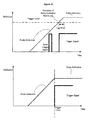
- FIG. 4A An example of a probe moving at a constant relative velocity towards a workpiece is shown in the plots of Figure 4A .
- the deflection of the probe is shown linearly increasing with time until the deflection is maintained after a trigger signal is generated.
- the probe deflection stops increasing after a lag after the trigger signal is generated.
- the trigger signal is generated when a deflection amount reaches a predetermined threshold trigger level shown in the upper plot by a broken line.
- a false trigger signal is also shown in the plot on the upper portion of Figure 4A . As shown, the trigger signal remains "high" (on) once triggered when in contact. Additionally, the false trigger signal may remain high for a short duration once triggered.
- a false trigger signal can be caused by, for example, vibration. If the false trigger signal is accepted, the probe will be stopped and coordinate measurements taken. In Figure 4A , the probe is only stopped when the true trigger signal is generated based on the deflection trigger level. The deflection trigger level is measured based on the measured deflection of the probe, and used to signal the coordinate measuring machine to stop the probe movement and take coordinate measurements.
- FIG. 4A shows the plot of deflection versus time using the high speed contact detector for measurement sensors.
- a trigger time is set rather than a trigger level, and the trigger time is set using earlier measurements of the probe characteristics.
- the earlier measurements of probe characteristics can be fitted, and the trigger time on the plot can be derived from the fit.
- the trigger time can also take into account any consistent signal delay or processing delay that is expected to consistently occur, so that the triggered coordinate measurements are properly timed when expected based on the fit from earlier probe characteristics.
- a second signal is used to indicate a halt.
- a halt signal is shown in Figure 4B .
- the halt signal is generated by a halt trigger, which is similar to the trigger signal, but at a higher (voltage) level.
- the halt signal is used to avoid the false trigger signals, by confirming the earlier trigger signal when the signal (voltage) for the deflection continues to rise in an expected manner that confirms the trigger.
- the coordinate axis positions of the probe deflection are logged, but the motion of the probe continues.
- the halt signal Only if the halt signal is triggered is the probe stopped and will the logged coordinate axis positions be used as a measurement point of the coordinates. In the case where a trigger is generated, but not a halt signal, the trigger is considered to be a false trigger and the logged axis positions are discarded. Restated, the halt signal is used as confirmation that the earlier logged axis positions of coordinate measurements were properly taken, and false triggers are eliminated when there is no subsequent proper halt signal.
- the lower part of Figure 4b shows the plot of deflection versus time using the high speed contact detector for measurement sensors.
- a trigger time is again set rather than a trigger level and a halt level, and the trigger time is set using earlier measurements of the probe characteristics.
- the earlier measurements of probe characteristics can be fitted, and the trigger time on the plot can be derived from the fit.
- the trigger time can also take into account any consistent signal delay or processing delay that is expected to consistently occur, so that the triggered coordinate measurements are properly timed when expected based on the fit from earlier probe characteristics.
- the halt signal is avoided entirely in the lower part of Figure 4B .
- the time spent waiting for a confirmatory halt is also eliminated. Therefore, the probe is moved, probe characteristics are captured, and a trigger time is identified based on a fit of the earlier captured probe characteristics captured in the same movement of the probe.
- the second signal used to indicate a halt can be used by the high speed contact detector.
- the halt signal may have the same functionality as in the conventional contact detector.
- an algorithm used to predict contact including both the fitting and the extrapolation as described herein may also be used to predict or otherwise set the halt level detection.
- the triggered measurements of coordinates may also be taken twice, such as both when contact between a probe and work piece is detected (in-contact motion), and when contact between the probe and work piece is lost (out-of-contact motion).
- two triggers can be generated, both at the same trigger level, and such a process uses the same timing feedback of probe characteristics during the same motion. That is, once a probe begins retreating from a workpiece, probe characteristics such as deflection can be taken and used to determine when coordinates should be taken.
- a second trigger level can be used to set the coordinate measuring time for the out-of-contact motion, and for probe withdrawals it is possible to use a much lower trigger value.
- probe characteristics can be used to generate a fit from which a trigger level as low as (almost) zero can be extrapolated. That is, as described herein, a process using existing characteristic measurements from the same motion can be used to extrapolate a trigger level as low as zero, i.e. from which a trigger time can be set for when the probing force is (almost) zero and the probe is almost entirely out of contact with the workpiece.
- Different (order) fits can also be generated for different approach directions, such as a linear fit in an X direction and a second order fit in a Y direction.
- different order fits can be generated for different coordinate measurement machines, so that instructions for generating the fit can be varied for different models and different circumstances.
- An operator can input the order of a fit to generate for different coordinate measuring machines and different probes, workpieces, and generally for different circumstances.
- a fit may be considered a filter to improve signal reliability
- fits can also be used with other filters to improve signal reliability. Multiple fits could be implemented, where the most appropriate fit is dynamically identified based on the measured or estimated probe velocity.
- the function parameters for the equation that describes the fit can be obtained by performing a linear regression using measured probe deflection values.
- the calculated function parameters represent the least squares estimator, meaning that the squared errors of the probe deflection are summed to calculate the function parameters. Theoretically, as few as two data points are sufficient to solve the regression and generate the function parameters for the equation that describes the fit. However, more data points make it is possible to attenuate disturbances, like measurement noise, that are present in the signal.
- the fitting procedure can be implemented on a controller, wherein most of the calculations are pre-performed or performed externally, and only a linear polynomial is evaluated locally in real time.
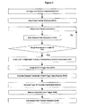
- FIG. 2 shows a process for the high speed contact detector for measurement sensors, according to an aspect of the present disclosure.
- a trigger value is set for a probe characteristic at S205.
- the probe characteristic may be a deflection in one or more dimensions, or may be a different probe characteristic that can be consistently and accurately measured by a contact detector.
- the probe is moved towards the workpiece.
- the probe characteristic is measured, and at S220, data of the probe characteristic is buffered. A series of measured probe characteristics from the probe movement are generated in order to generate the equation that describes the fit.
- the process returns to S215 as the probe continues moving and the probe characteristics are again measured at S215 and data buffered at S220.
- the probe characteristics can be continually measured even when there are enough measurements to create a desired fit, so as to, for example, create an updated fit or verify the first equation generated to describe the fit.
- the linear or higher order fit is created based on the buffered data of the probe characteristics at S230.
- An extrapolation of the fit equation then projects to the trigger value at S235, and an expected time or iteration number until the trigger value is reached is calculated at S240.
- the fit process creates an equation that corresponds to a line or curve on a plot of the characteristic (deflection in this example) versus time.
- a time until the threshold characteristic will be reached is calculated/projected.
- the trigger is then generated for the expected time at S245.
- the coordinates that are the actual objective of the coordinate measuring machine are then measured at S250 at the expected/calculated/projected time.
- the relative movement of the probe towards the workpiece is stopped, and the process of Figure 2 is restarted again to measure another coordinate point on the workpiece.
- the restarted process of Figure 2 is a movement to approach the probe towards the workpiece from another angle and/or direction, so as to identify another coordinate of the workpiece shape.
- a process with steps such as those shown in Figure 2 can be used for out-of-contact motion to identify when a threshold is met to confirm that a probe is out of contact with a workpiece.
- the algorithm in the process can also calculate the expected number of points until the trigger should be given.
- a data point is not automatically collected at every iteration of time or, for example, spatial movement.
- the trigger can be generated at any iteration of time or spatial movement by the controller, even if no measurement of the characteristic would otherwise be taken due to the interval spacing requirements.
- the algorithm can calculate the expected amount of time or number of iterations (steps) until the trigger should be set, and then trigger the coordinate measurement even at a time that is not one of the corresponding times at which the characteristic measurement would be taken in the interval-spaced process.
- the controller can be programmed to create a trigger before the next schedule time at which a data point could be scheduled in the interval timing.
- the coordinates of the probe are taken as in S255 of Figure 2 .
- the controller waits the calculated number of time steps (iterations) and generates the trigger.
- the trigger algorithm used by the control system can be used on the way in when the probe is moved towards the workpiece, and on the way out when the probe is moved from the workpiece.
- the trigger algorithm used by the control system can also be used both on the way in and on the way out.
- a trigger may be set to take a coordinate measurement on the way out when the contact is almost zero, based on the extrapolated timing obtained from the fit for the probe characteristic in the withdrawing motion of the probe.
- the high speed contact detector for measurement sensors accomplishes a highly accurate result for a touch-trigger signal which is used to measure probe coordinates.
- the touch-trigger signal is generated at a constant deflection, in a manner that is highly repeatable, and provides consistent results for the probe in different measurements of a workpiece.
- the number of false triggers is reduced by setting a time or corresponding iteration number based on previous measurements in the same movement, rather than on a level of the characteristic that is measured and determined in real-time to meet a threshold.
- the high speed contact detector for measurement sensors minimizes any delay between the actual (physical) probe trigger deflection and the generation of the touch-trigger signal by the controller, and can compensate for a consistent signal or processing delay. Further, false triggers can be avoided by not accepting, or ignoring, discarding, or otherwise not using false triggers that are physically generated due to noise effects such as vibrations before the time or corresponding iteration number set for the trigger.
- Figure 6 shows a small series of progressive deflections of types that can measured as probe characteristics and used in the manner described herein.
- a relative approach between a triangular probe and a vertical workpiece is shown where the angles of the triangular probe increase as the probe is pressed against the workpiece.
- the triangular probe is shown progressing into the vertical workpiece.
- the previous measurements of the characteristic can be taken from measurements in the same high speed process and probe movement for the same workpiece.
- the trigger set in the manner described herein may be therefore reflective of the particular parameters and characteristics of the workpiece being measured, the high speed contact detector being used for the measurements, the processing device, the order of the fit set by an operator, and other details particular to the immediate environment in which the trigger is being set.
- Delay can also be minimized by the use of a fixed time window or windows, which allow(s) pre-computing of the time component of the fit, and helps avoid requiring real-time and local processing for this time component as the high speed contact detector is operating. This will greatly reduce the computational effort and load on the local controller in real time, which in turn results in a faster algorithm, which may be especially useful for parallel real-time computation processes, such as in an FPGA. Additionally, as described herein, the algorithm can be performed without calculating an inverse matrix explicitly, and with a reduced number of computations and a reduced sample delay.
- Temporal spacing refers to the way in which data points are collected, and allows spaced sampling that does not take a sample at every time or iteration in the process at which a sample can otherwise be taken.
- An algorithm without temporal spacing will simply collect all available measurement points and use these points in further data processing.
- An algorithm with temporal spacing will take a data point at an interval, for example every 10th available measurement point is recorded.
- t i indicates the time instant i at which a measured value of the 3D probe deflection d meas (t i ) has been taken.
- M fit (1, j) and M fit (2, j) represent the elements of column j of the fit matrix M fit .
- a - 1 1 det
- a ⁇ adj A 1 a 11 ⁇ a 22 - a 12 ⁇ a 21 ⁇ a 22 - a 12 - a 21 a 11 .
- the fit vector ⁇ and trigger level S trigger are used at S330 to calculate a number of points ⁇ until the trigger level is reached.
- a trigger delay compensation is obtained at S335 and applied at S340, to compensate for consistent signal or processing delays in generating a trigger, and then the trigger is generated at S345 to ⁇ *, which is the time for the calculated number of measurement points plus the trigger delay compensation.
- the measurement of coordinates is triggered.
- the process can be repeated each time a new probe deflection measurement is obtained at S310, so that a new trigger time is calculated.
- the deflection values obtained at S310 and buffered at S315 are used to obtain a trigger time when coordinates will be measured in the process described herein.
- the deflection values are broadly described as probe characteristics in this description, in the understanding that other similar characteristics that change in line with progressive contact between the probe and a workpiece can also be described as probe characteristics.
- the fit can be extrapolated to predict whether the trigger threshold level will be crossed during the next sample. This helps ensure that an optimal coordinate measurement point is not missed when the next time or iteration for characteristic measurement is beyond the time for the optimal coordinate measurement point.
- the intercept term ⁇ 0 represents the current filtered probe deflection, while the slope term ⁇ 1 gives the change in deflection of the fit per sample.
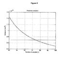
- Another factor considered in the process described herein is the number of measurement points used in order to attenuate the noise to a reasonably accurate prediction.
- a control unit described herein may execute software instructions.
- a T-matrix may be used for one particular probe to calculate X, Y, Z tip displacement, based on probe signals A, B, C.
- a fit parameter vector is obtained from the measured deflection values of the probe, taking into account the offsets as described herein. The fit parameter vector is then used to generate a trigger time by the process described herein. At the calculated trigger time, coordinates of the probe are taken, and the probe is stopped.
- software instructions executed by a control unit would cause a contact detector to measure contact between a probe and a workpiece 74 or more times.
- the contact characteristic measurements are then used to create a fit, which then projects a time ahead at which the contact characteristic measurements will meet a threshold.
- the time at which the threshold will be met is then set as the trigger time for taking the coordinate measurements, taking into account any expected processing or signaling delays.
- the high speed contact detector for measurement sensors has been described with reference to several exemplary embodiments, it is understood that the words that have been used are words of description and illustration, rather than words of limitation. Changes may be made within the purview of the appended claims, as presently stated and as amended, without departing from the scope and spirit of the high speed contact detector for measurement sensors in its aspects. Although the high speed contact detector for measurement sensors has been described with reference to particular means, materials and embodiments, the high speed contact detector for measurement sensors is not intended to be limited to the particulars disclosed; rather the high speed contact detector for measurement sensors extends to all functionally equivalent structures, methods, and uses such as are within the scope of the appended claims.
- a method of measuring a workpiece using a contact detector includes moving the contact detector relatively towards a workpiece.
- a characteristic of the contact detector that changes as the contact detector contacts the workpiece is measured at a plurality of times.
- a projected time when the characteristic of the contact detector will meet a predetermined threshold is extrapolated from the characteristic measured the plurality of times using a processor of a computer.
- a trigger is set to measure coordinates of the workpiece at the projected time.
- a measurement of coordinates of the workpiece is triggered at the projected time based on the set trigger.
- the method further includes discarding a measurement of the characteristic that meets the predetermined threshold based on a time the measurement is taken.
- the time the measurement of the characteristic is taken is before the projected time
- the reason for discarding the measurement of the characteristic is that the measurement of the characteristic was taken before the projected time
- data of the measured characteristics at the plurality of times is buffered as the measurements of the characteristic are taken, and fit in accordance with a regression to a projectable equation from which the projected time is extrapolated.
- the method further includes determining an expected number of iterations of the measuring of the characteristic until the projected time based on the projectable equation.
- the method further includes pre-computing a matrix before measuring the workpiece using the contact detector, and using the matrix as a time component in the projectable equation when measuring the workpiece using the contact detector.
- the matrix used by the contact detector may be pre-computed before the contact detection process, and using a device different than the controller described herein.
- the method further includes using the data of the measured characteristic at the plurality of times as a magnitude component in the projectable equation.
- the characteristic comprises a deflection of the contact detector based on contact with the workpiece.
- the deflection is measured in a plurality of dimensions.
- the measured characteristics at the plurality of times are buffered as they are taken, and fit in accordance with a multi-dimensional regression to a projectable equation from which the projected time is extrapolated.
- An expected number of iterations of the measuring of the characteristic until the projected time is determined based on the projectable equation.
- the deflection is incrementally increased at a substantially constant rate over time.
- the probe is moved at a substantially constant velocity during the plurality of times the measurements of the characteristic are taken.
- the method further includes offsetting a processing time during which processing delays are estimated to occur, so that the triggering of the measurement of the coordinates of the workpiece at the projected time is initiated in advance of the projected time by an amount of the processing time.
- the method further includes using fewer than all available measurements of the characteristic in extrapolating the projected time.
- the method further includes discarding a trigger to take measurement of the coordinates of the workpiece without taking the measurement of the coordinates of the workpiece based on the trigger occurring prior to the projected time.
- the contact detector is moved relatively towards the workpiece at a predetermined constant velocity as the characteristic of the contact detector is measured the plurality of times.
- the method further includes retracting the contact detector after the coordinates of the workpiece are measured at the projected time based on the set trigger.
- the method further includes identifying a coordinate location of the contact detector at the projected time based on the set trigger.
- the projected time is extrapolated using a fit that is dynamically varied for different measurements of the contact detector as the contact detector is relatively moved towards the same workpiece, and in accordance with a regression to a projectable equation from which the projected time is extrapolated.
- a computer apparatus measures a workpiece using a contact detector.
- a memory stores instructions.
- a processor executes the instructions. When executed by the processor, the instructions cause the processor to perform operations including moving the contact detector relatively towards a workpiece.
- a characteristic of the contact detector that changes as the contact detector contacts the workpiece is measured at a plurality of times.
- a projected time when the characteristic of the contact detector will meet a predetermined threshold is extrapolated from the characteristic measured the plurality of times and using a processor of a computer.
- a trigger is set to measure coordinates of the workpiece at the projected time. A measurement of the coordinates of the workpiece is triggered at the projected time based on the set trigger
- a tangible computer readable storage medium stores a computer program for measuring a workpiece using a contact detector.
- the computer program when executed by a processor, causes a computer apparatus to perform a process including moving the contact detector relatively towards a workpiece.
- a characteristic of the contact detector that changes as the contact detector contacts the workpiece is measured at a plurality of times.
- a projected time when the characteristic of the contact detector will meet a predetermined threshold is extrapolated from the characteristic measured the plurality of times and using a processor of a compute.
- a trigger is set to measure coordinates of the workpiece at the projected time.
- a measurement of the coordinates of the workpiece is triggered at the projected time based on the set trigger
- While the computer-readable medium is shown to be a single medium, the term “computer-readable medium” includes a single medium or multiple media, such as a centralized or distributed database, and/or associated caches and servers that store one or more sets of instructions.
- the term “computer-readable medium” shall also include any medium that is capable of storing, encoding or carrying a set of instructions for execution by a processor or that cause a computer system to perform any one or more of the methods or operations disclosed herein.
- the computer-readable medium can include a solid-state memory such as a memory card or other package that houses one or more non-volatile read-only memories.
- the computer-readable medium can be a random access memory or other volatile re-writable memory.
- the computer-readable medium can include a magneto-optical or optical medium, such as a disk or tapes or other storage device to capture carrier wave signals such as a signal communicated over a transmission medium. Accordingly, the disclosure is considered to include any computer-readable medium or other equivalents and successor media, in which data or instructions may be stored.
- inventions of the disclosure may be referred to herein, individually and/or collectively, by the term "invention" merely for convenience and without intending to voluntarily limit the scope of this application to any particular invention or inventive concept.
- inventions may be referred to herein, individually and/or collectively, by the term "invention" merely for convenience and without intending to voluntarily limit the scope of this application to any particular invention or inventive concept.
- specific embodiments have been illustrated and described herein, it should be appreciated that any subsequent arrangement designed to achieve the same or similar purpose may be substituted for the specific embodiments shown.
- This disclosure is intended to cover any and all subsequent adaptations or variations of various embodiments. Combinations of the above embodiments, and other embodiments not specifically described herein, will be apparent to those of skill in the art upon reviewing the description.
Landscapes
- Physics & Mathematics (AREA)
- General Physics & Mathematics (AREA)
- Length Measuring Devices With Unspecified Measuring Means (AREA)
- A Measuring Device Byusing Mechanical Method (AREA)
Applications Claiming Priority (1)
| Application Number | Priority Date | Filing Date | Title |
|---|---|---|---|
| US14/273,980 US9250055B2 (en) | 2014-05-09 | 2014-05-09 | High speed contact detector for measurement sensors |
Publications (2)
| Publication Number | Publication Date |
|---|---|
| EP2942601A1 true EP2942601A1 (de) | 2015-11-11 |
| EP2942601B1 EP2942601B1 (de) | 2016-06-08 |
Family
ID=53039775
Family Applications (1)
| Application Number | Title | Priority Date | Filing Date |
|---|---|---|---|
| EP15166163.4A Active EP2942601B1 (de) | 2014-05-09 | 2015-05-04 | Schneller kontaktdetektor für messfühler |
Country Status (4)
| Country | Link |
|---|---|
| US (1) | US9250055B2 (de) |
| EP (1) | EP2942601B1 (de) |
| JP (1) | JP6122457B2 (de) |
| CN (1) | CN105091832B (de) |
Families Citing this family (9)
| Publication number | Priority date | Publication date | Assignee | Title |
|---|---|---|---|---|
| JP6608726B2 (ja) * | 2016-02-18 | 2019-11-20 | 株式会社東京精密 | 位置決め測定システム |
| CN109313004B (zh) | 2016-04-21 | 2021-10-08 | 株式会社三丰 | 坐标测量探针主体 |
| DE102016212650B4 (de) * | 2016-07-12 | 2021-07-08 | Carl Zeiss Industrielle Messtechnik Gmbh | Verfahren und Vorrichtung zur Erzeugung von verorteten Sensordaten eines Koordinatenmessgeräts |
| DE102016015969B4 (de) | 2016-07-12 | 2026-04-30 | Carl Zeiss Industrielle Messtechnik Gmbh | Verfahren und Vorrichtung zur Erzeugung von verorteten Sensordaten eines Koordinatenmessgeräts |
| US10101141B2 (en) | 2016-12-07 | 2018-10-16 | Mitutoyo Corporation | Trigger counter for measurement device with count values stored in flash memory |
| US10145666B2 (en) | 2016-12-19 | 2018-12-04 | Mitutoyo Corporation | Touch probe for CMM including digital signal communication |
| US10352679B2 (en) | 2017-03-31 | 2019-07-16 | Mitutoyo Corporation | Compact coordinate measurement machine configuration with large working volume relative to size |
| US9835433B1 (en) | 2017-05-09 | 2017-12-05 | Tesa Sa | Touch trigger probe |
| JP7189707B2 (ja) * | 2018-09-05 | 2022-12-14 | 株式会社ミツトヨ | 測定点決定方法、プログラム、および測定点決定装置 |
Citations (3)
| Publication number | Priority date | Publication date | Assignee | Title |
|---|---|---|---|---|
| US6487785B1 (en) * | 1999-06-18 | 2002-12-03 | Dr. Johammes Heidenvain Gmbh | Method and circuit for adjusting a switching threshold of a touch probe |
| WO2009112819A2 (en) * | 2008-03-11 | 2009-09-17 | Renishaw Plc | Touch trigger measurement probe |
| WO2010084302A2 (en) * | 2009-01-20 | 2010-07-29 | Renishaw Plc | Method for optimising a measurement cycle |
Family Cites Families (24)
| Publication number | Priority date | Publication date | Assignee | Title |
|---|---|---|---|---|
| DE3763885D1 (de) * | 1986-04-17 | 1990-08-30 | Renishaw Plc | Probe fuer kontakt-sensor. |
| DE3623614A1 (de) * | 1986-07-12 | 1988-01-14 | Zeiss Carl Fa | Koordinatenmessgeraet mit einem tastkopf vom schaltenden typ |
| US5222034A (en) * | 1990-10-10 | 1993-06-22 | Shelton Russell S | Measuring method and apparatus |
| DE4204602A1 (de) | 1992-02-15 | 1993-08-19 | Zeiss Carl Fa | Verfahren zur koordinatenmessung an werkstuecken |
| DE4330873A1 (de) * | 1993-09-13 | 1995-03-16 | Zeiss Carl Fa | Koordinatenmeßgerät mit einem Tastkopf und einer Elektronik zur Verarbeitung des Tastsignals |
| JPH08136241A (ja) | 1994-11-04 | 1996-05-31 | Mitsutoyo Corp | タッチ信号の判別方法 |
| DE19525592A1 (de) | 1995-07-13 | 1997-01-16 | Zeiss Carl Fa | Verfahren zur Koordinatenmessung an Werkstücken |
| JP2889196B2 (ja) * | 1996-10-08 | 1999-05-10 | 株式会社ミツトヨ | センサ信号の直流レベル変化検知回路 |
| DE69814198T2 (de) * | 1997-02-10 | 2004-04-08 | Mitutoyo Corp., Kawasaki | Messverfahren und Messinstrument mit Triggersonde |
| JP2000199710A (ja) * | 1999-01-06 | 2000-07-18 | Mitsutoyo Corp | タッチ信号プロ―ブの接触部位検出構造 |
| DE10016070B4 (de) * | 1999-04-02 | 2019-04-18 | Mitutoyo Corporation | Bewegungssteuervorrichtung einer Schwingsonde eines Kontakttyps |
| US6810597B2 (en) * | 1999-04-08 | 2004-11-02 | Renishaw Plc | Use of surface measuring probes |
| JP3820357B2 (ja) | 2001-08-07 | 2006-09-13 | 株式会社ミツトヨ | 計測方法および計測装置 |
| GB0215478D0 (en) * | 2002-07-04 | 2002-08-14 | Renishaw Plc | Method of scanning a calibrating system |
| GB0329098D0 (en) * | 2003-12-16 | 2004-01-21 | Renishaw Plc | Method of calibrating a scanning system |
| CN100483070C (zh) * | 2004-05-27 | 2009-04-29 | 约翰尼斯海登海恩博士股份有限公司 | 用于坐标测量的装置和方法 |
| WO2007009458A2 (en) | 2005-07-15 | 2007-01-25 | Pinocchio Data Systems Aps | Time synchronization algorithm for measurement systems with random delays |
| JP5177830B2 (ja) * | 2006-03-22 | 2013-04-10 | 株式会社キーエンス | 接触式変位検出装置及び接触式変位検出装置における許容範囲指定方法 |
| GB0703423D0 (en) * | 2007-02-22 | 2007-04-04 | Renishaw Plc | Calibration method and apparatus |
| JP5108619B2 (ja) | 2008-05-15 | 2012-12-26 | 株式会社ミツトヨ | センサ信号検知回路 |
| JP5523995B2 (ja) * | 2010-09-03 | 2014-06-18 | 株式会社ミツトヨ | 測定装置 |
| JP6113958B2 (ja) * | 2012-01-13 | 2017-04-12 | 株式会社ミツトヨ | 測定座標補正方法、及び三次元測定機 |
| EP2629048B1 (de) * | 2012-02-20 | 2018-10-24 | Tesa Sa | Messtaster |
| WO2013156767A1 (en) * | 2012-04-18 | 2013-10-24 | Renishaw Plc | A method of finding a feature using a machine tool |
-
2014
- 2014-05-09 US US14/273,980 patent/US9250055B2/en active Active
-
2015
- 2015-03-11 JP JP2015048806A patent/JP6122457B2/ja active Active
- 2015-05-04 EP EP15166163.4A patent/EP2942601B1/de active Active
- 2015-05-08 CN CN201510232918.3A patent/CN105091832B/zh active Active
Patent Citations (3)
| Publication number | Priority date | Publication date | Assignee | Title |
|---|---|---|---|---|
| US6487785B1 (en) * | 1999-06-18 | 2002-12-03 | Dr. Johammes Heidenvain Gmbh | Method and circuit for adjusting a switching threshold of a touch probe |
| WO2009112819A2 (en) * | 2008-03-11 | 2009-09-17 | Renishaw Plc | Touch trigger measurement probe |
| WO2010084302A2 (en) * | 2009-01-20 | 2010-07-29 | Renishaw Plc | Method for optimising a measurement cycle |
Also Published As
| Publication number | Publication date |
|---|---|
| JP2015215336A (ja) | 2015-12-03 |
| JP6122457B2 (ja) | 2017-04-26 |
| US9250055B2 (en) | 2016-02-02 |
| CN105091832B (zh) | 2018-01-12 |
| EP2942601B1 (de) | 2016-06-08 |
| US20150323300A1 (en) | 2015-11-12 |
| CN105091832A (zh) | 2015-11-25 |
Similar Documents
| Publication | Publication Date | Title |
|---|---|---|
| EP2942601B1 (de) | Schneller kontaktdetektor für messfühler | |
| JP6980132B2 (ja) | 分散型センサの時空間ノイズ除去 | |
| CN101140161B (zh) | 表面形状测定装置 | |
| JP6423219B2 (ja) | 構造物の安全性診断システム | |
| US9562941B2 (en) | Method of locating an event transmitting a signal | |
| CN110217660B (zh) | 电梯测量数据的检测方法、装置和电梯检测系统 | |
| US10190861B2 (en) | Measuring device and related methods | |
| WO2014065966A1 (en) | Ultrasonic measurement apparatus and method | |
| CN108303989A (zh) | 一种用于移动机器人沿墙运动的方法及设备 | |
| US20260043216A1 (en) | Method for calibrating coordinates of a bucket, method for updating coordinate calibration, computer device, calibration system, non-transitory computer-readable storage medium and excavator | |
| CN107076552B (zh) | 用于工件的单点扫描的方法和坐标测量机 | |
| JP2014001925A5 (de) | ||
| US8970233B2 (en) | Nondestructive inspection system controller with dynamic position correction | |
| CN116026263B (zh) | 测厚校准方法、装置、设备和存储介质 | |
| CN114994641A (zh) | 一种参数标定方法、装置、电子设备及存储介质 | |
| Mazur et al. | Accuracy analysis of the curved profile measurement with CMM: A case study | |
| Sakaris et al. | Vibration-based multi-site damage precise localization via the Functional Model Based Method | |
| KR101392303B1 (ko) | 웨이블릿 변환을 이용한 주파수 해석식 자왜센서 | |
| US9797699B2 (en) | Off-axis loadcell force sensing to automatically determine location of specimen features | |
| Leonetti et al. | Measurement of crack paths using digital image correlation | |
| CN103592366A (zh) | 一种检验超声波探伤的方法 | |
| Adib et al. | Root-MSE geolocation performance using angle-of-arrival measurements | |
| CN120921398A (zh) | 机器人控制系统、方法、装置、机器人设备、介质及程序 | |
| CN121230818B (zh) | 一种门窗框架快速拼接结构质量检测方法及系统 | |
| CN111007553A (zh) | 被测对象的导航方法、装置、计算机设备和存储介质 |
Legal Events
| Date | Code | Title | Description |
|---|---|---|---|
| PUAI | Public reference made under article 153(3) epc to a published international application that has entered the european phase |
Free format text: ORIGINAL CODE: 0009012 |
|
| AK | Designated contracting states |
Kind code of ref document: A1 Designated state(s): AL AT BE BG CH CY CZ DE DK EE ES FI FR GB GR HR HU IE IS IT LI LT LU LV MC MK MT NL NO PL PT RO RS SE SI SK SM TR |
|
| AX | Request for extension of the european patent |
Extension state: BA ME |
|
| 17P | Request for examination filed |
Effective date: 20151014 |
|
| RBV | Designated contracting states (corrected) |
Designated state(s): AL AT BE BG CH CY CZ DE DK EE ES FI FR GB GR HR HU IE IS IT LI LT LU LV MC MK MT NL NO PL PT RO RS SE SI SK SM TR |
|
| GRAP | Despatch of communication of intention to grant a patent |
Free format text: ORIGINAL CODE: EPIDOSNIGR1 |
|
| INTG | Intention to grant announced |
Effective date: 20151218 |
|
| GRAS | Grant fee paid |
Free format text: ORIGINAL CODE: EPIDOSNIGR3 |
|
| GRAA | (expected) grant |
Free format text: ORIGINAL CODE: 0009210 |
|
| AK | Designated contracting states |
Kind code of ref document: B1 Designated state(s): AL AT BE BG CH CY CZ DE DK EE ES FI FR GB GR HR HU IE IS IT LI LT LU LV MC MK MT NL NO PL PT RO RS SE SI SK SM TR |
|
| REG | Reference to a national code |
Ref country code: GB Ref legal event code: FG4D |
|
| REG | Reference to a national code |
Ref country code: CH Ref legal event code: EP |
|
| REG | Reference to a national code |
Ref country code: IE Ref legal event code: FG4D |
|
| REG | Reference to a national code |
Ref country code: AT Ref legal event code: REF Ref document number: 805563 Country of ref document: AT Kind code of ref document: T Effective date: 20160715 |
|
| REG | Reference to a national code |
Ref country code: DE Ref legal event code: R096 Ref document number: 602015000064 Country of ref document: DE |
|
| REG | Reference to a national code |
Ref country code: LT Ref legal event code: MG4D |
|
| REG | Reference to a national code |
Ref country code: NL Ref legal event code: MP Effective date: 20160608 |
|
| PG25 | Lapsed in a contracting state [announced via postgrant information from national office to epo] |
Ref country code: LT Free format text: LAPSE BECAUSE OF FAILURE TO SUBMIT A TRANSLATION OF THE DESCRIPTION OR TO PAY THE FEE WITHIN THE PRESCRIBED TIME-LIMIT Effective date: 20160608 Ref country code: FI Free format text: LAPSE BECAUSE OF FAILURE TO SUBMIT A TRANSLATION OF THE DESCRIPTION OR TO PAY THE FEE WITHIN THE PRESCRIBED TIME-LIMIT Effective date: 20160608 Ref country code: NO Free format text: LAPSE BECAUSE OF FAILURE TO SUBMIT A TRANSLATION OF THE DESCRIPTION OR TO PAY THE FEE WITHIN THE PRESCRIBED TIME-LIMIT Effective date: 20160908 |
|
| REG | Reference to a national code |
Ref country code: AT Ref legal event code: MK05 Ref document number: 805563 Country of ref document: AT Kind code of ref document: T Effective date: 20160608 |
|
| PG25 | Lapsed in a contracting state [announced via postgrant information from national office to epo] |
Ref country code: RS Free format text: LAPSE BECAUSE OF FAILURE TO SUBMIT A TRANSLATION OF THE DESCRIPTION OR TO PAY THE FEE WITHIN THE PRESCRIBED TIME-LIMIT Effective date: 20160608 Ref country code: GR Free format text: LAPSE BECAUSE OF FAILURE TO SUBMIT A TRANSLATION OF THE DESCRIPTION OR TO PAY THE FEE WITHIN THE PRESCRIBED TIME-LIMIT Effective date: 20160909 Ref country code: SE Free format text: LAPSE BECAUSE OF FAILURE TO SUBMIT A TRANSLATION OF THE DESCRIPTION OR TO PAY THE FEE WITHIN THE PRESCRIBED TIME-LIMIT Effective date: 20160608 Ref country code: NL Free format text: LAPSE BECAUSE OF FAILURE TO SUBMIT A TRANSLATION OF THE DESCRIPTION OR TO PAY THE FEE WITHIN THE PRESCRIBED TIME-LIMIT Effective date: 20160608 Ref country code: LV Free format text: LAPSE BECAUSE OF FAILURE TO SUBMIT A TRANSLATION OF THE DESCRIPTION OR TO PAY THE FEE WITHIN THE PRESCRIBED TIME-LIMIT Effective date: 20160608 Ref country code: ES Free format text: LAPSE BECAUSE OF FAILURE TO SUBMIT A TRANSLATION OF THE DESCRIPTION OR TO PAY THE FEE WITHIN THE PRESCRIBED TIME-LIMIT Effective date: 20160608 Ref country code: HR Free format text: LAPSE BECAUSE OF FAILURE TO SUBMIT A TRANSLATION OF THE DESCRIPTION OR TO PAY THE FEE WITHIN THE PRESCRIBED TIME-LIMIT Effective date: 20160608 |
|
| PG25 | Lapsed in a contracting state [announced via postgrant information from national office to epo] |
Ref country code: RO Free format text: LAPSE BECAUSE OF FAILURE TO SUBMIT A TRANSLATION OF THE DESCRIPTION OR TO PAY THE FEE WITHIN THE PRESCRIBED TIME-LIMIT Effective date: 20160608 Ref country code: SK Free format text: LAPSE BECAUSE OF FAILURE TO SUBMIT A TRANSLATION OF THE DESCRIPTION OR TO PAY THE FEE WITHIN THE PRESCRIBED TIME-LIMIT Effective date: 20160608 Ref country code: EE Free format text: LAPSE BECAUSE OF FAILURE TO SUBMIT A TRANSLATION OF THE DESCRIPTION OR TO PAY THE FEE WITHIN THE PRESCRIBED TIME-LIMIT Effective date: 20160608 Ref country code: IT Free format text: LAPSE BECAUSE OF FAILURE TO SUBMIT A TRANSLATION OF THE DESCRIPTION OR TO PAY THE FEE WITHIN THE PRESCRIBED TIME-LIMIT Effective date: 20160608 Ref country code: CZ Free format text: LAPSE BECAUSE OF FAILURE TO SUBMIT A TRANSLATION OF THE DESCRIPTION OR TO PAY THE FEE WITHIN THE PRESCRIBED TIME-LIMIT Effective date: 20160608 Ref country code: IS Free format text: LAPSE BECAUSE OF FAILURE TO SUBMIT A TRANSLATION OF THE DESCRIPTION OR TO PAY THE FEE WITHIN THE PRESCRIBED TIME-LIMIT Effective date: 20161008 |
|
| PG25 | Lapsed in a contracting state [announced via postgrant information from national office to epo] |
Ref country code: BE Free format text: LAPSE BECAUSE OF FAILURE TO SUBMIT A TRANSLATION OF THE DESCRIPTION OR TO PAY THE FEE WITHIN THE PRESCRIBED TIME-LIMIT Effective date: 20160608 Ref country code: PT Free format text: LAPSE BECAUSE OF FAILURE TO SUBMIT A TRANSLATION OF THE DESCRIPTION OR TO PAY THE FEE WITHIN THE PRESCRIBED TIME-LIMIT Effective date: 20161010 Ref country code: PL Free format text: LAPSE BECAUSE OF FAILURE TO SUBMIT A TRANSLATION OF THE DESCRIPTION OR TO PAY THE FEE WITHIN THE PRESCRIBED TIME-LIMIT Effective date: 20160608 Ref country code: AT Free format text: LAPSE BECAUSE OF FAILURE TO SUBMIT A TRANSLATION OF THE DESCRIPTION OR TO PAY THE FEE WITHIN THE PRESCRIBED TIME-LIMIT Effective date: 20160608 Ref country code: SM Free format text: LAPSE BECAUSE OF FAILURE TO SUBMIT A TRANSLATION OF THE DESCRIPTION OR TO PAY THE FEE WITHIN THE PRESCRIBED TIME-LIMIT Effective date: 20160608 |
|
| REG | Reference to a national code |
Ref country code: DE Ref legal event code: R097 Ref document number: 602015000064 Country of ref document: DE |
|
| PLBE | No opposition filed within time limit |
Free format text: ORIGINAL CODE: 0009261 |
|
| STAA | Information on the status of an ep patent application or granted ep patent |
Free format text: STATUS: NO OPPOSITION FILED WITHIN TIME LIMIT |
|
| 26N | No opposition filed |
Effective date: 20170309 |
|
| REG | Reference to a national code |
Ref country code: FR Ref legal event code: PLFP Year of fee payment: 3 |
|
| PG25 | Lapsed in a contracting state [announced via postgrant information from national office to epo] |
Ref country code: DK Free format text: LAPSE BECAUSE OF FAILURE TO SUBMIT A TRANSLATION OF THE DESCRIPTION OR TO PAY THE FEE WITHIN THE PRESCRIBED TIME-LIMIT Effective date: 20160608 Ref country code: SI Free format text: LAPSE BECAUSE OF FAILURE TO SUBMIT A TRANSLATION OF THE DESCRIPTION OR TO PAY THE FEE WITHIN THE PRESCRIBED TIME-LIMIT Effective date: 20160608 |
|
| PG25 | Lapsed in a contracting state [announced via postgrant information from national office to epo] |
Ref country code: LU Free format text: LAPSE BECAUSE OF NON-PAYMENT OF DUE FEES Effective date: 20170531 |
|
| PG25 | Lapsed in a contracting state [announced via postgrant information from national office to epo] |
Ref country code: MC Free format text: LAPSE BECAUSE OF FAILURE TO SUBMIT A TRANSLATION OF THE DESCRIPTION OR TO PAY THE FEE WITHIN THE PRESCRIBED TIME-LIMIT Effective date: 20160608 |
|
| REG | Reference to a national code |
Ref country code: IE Ref legal event code: MM4A |
|
| PG25 | Lapsed in a contracting state [announced via postgrant information from national office to epo] |
Ref country code: LU Free format text: LAPSE BECAUSE OF NON-PAYMENT OF DUE FEES Effective date: 20170504 |
|
| PG25 | Lapsed in a contracting state [announced via postgrant information from national office to epo] |
Ref country code: IE Free format text: LAPSE BECAUSE OF NON-PAYMENT OF DUE FEES Effective date: 20170504 |
|
| REG | Reference to a national code |
Ref country code: FR Ref legal event code: PLFP Year of fee payment: 4 |
|
| PG25 | Lapsed in a contracting state [announced via postgrant information from national office to epo] |
Ref country code: MT Free format text: LAPSE BECAUSE OF NON-PAYMENT OF DUE FEES Effective date: 20170504 |
|
| PG25 | Lapsed in a contracting state [announced via postgrant information from national office to epo] |
Ref country code: AL Free format text: LAPSE BECAUSE OF FAILURE TO SUBMIT A TRANSLATION OF THE DESCRIPTION OR TO PAY THE FEE WITHIN THE PRESCRIBED TIME-LIMIT Effective date: 20160608 |
|
| REG | Reference to a national code |
Ref country code: CH Ref legal event code: PL |
|
| PG25 | Lapsed in a contracting state [announced via postgrant information from national office to epo] |
Ref country code: LI Free format text: LAPSE BECAUSE OF NON-PAYMENT OF DUE FEES Effective date: 20180531 Ref country code: CH Free format text: LAPSE BECAUSE OF NON-PAYMENT OF DUE FEES Effective date: 20180531 |
|
| PG25 | Lapsed in a contracting state [announced via postgrant information from national office to epo] |
Ref country code: HU Free format text: LAPSE BECAUSE OF FAILURE TO SUBMIT A TRANSLATION OF THE DESCRIPTION OR TO PAY THE FEE WITHIN THE PRESCRIBED TIME-LIMIT; INVALID AB INITIO Effective date: 20150504 |
|
| PG25 | Lapsed in a contracting state [announced via postgrant information from national office to epo] |
Ref country code: BG Free format text: LAPSE BECAUSE OF FAILURE TO SUBMIT A TRANSLATION OF THE DESCRIPTION OR TO PAY THE FEE WITHIN THE PRESCRIBED TIME-LIMIT Effective date: 20160608 |
|
| PG25 | Lapsed in a contracting state [announced via postgrant information from national office to epo] |
Ref country code: CY Free format text: LAPSE BECAUSE OF FAILURE TO SUBMIT A TRANSLATION OF THE DESCRIPTION OR TO PAY THE FEE WITHIN THE PRESCRIBED TIME-LIMIT Effective date: 20160608 |
|
| PG25 | Lapsed in a contracting state [announced via postgrant information from national office to epo] |
Ref country code: MK Free format text: LAPSE BECAUSE OF FAILURE TO SUBMIT A TRANSLATION OF THE DESCRIPTION OR TO PAY THE FEE WITHIN THE PRESCRIBED TIME-LIMIT Effective date: 20160608 |
|
| PG25 | Lapsed in a contracting state [announced via postgrant information from national office to epo] |
Ref country code: TR Free format text: LAPSE BECAUSE OF FAILURE TO SUBMIT A TRANSLATION OF THE DESCRIPTION OR TO PAY THE FEE WITHIN THE PRESCRIBED TIME-LIMIT Effective date: 20160608 |
|
| PGFP | Annual fee paid to national office [announced via postgrant information from national office to epo] |
Ref country code: DE Payment date: 20250521 Year of fee payment: 11 |
|
| PGFP | Annual fee paid to national office [announced via postgrant information from national office to epo] |
Ref country code: GB Payment date: 20250521 Year of fee payment: 11 |
|
| PGFP | Annual fee paid to national office [announced via postgrant information from national office to epo] |
Ref country code: FR Payment date: 20250528 Year of fee payment: 11 |