EP2942113B1 - Entnahmeeinrichtung für einen Auffangbehälter - Google Patents
Entnahmeeinrichtung für einen Auffangbehälter Download PDFInfo
- Publication number
- EP2942113B1 EP2942113B1 EP14167418.4A EP14167418A EP2942113B1 EP 2942113 B1 EP2942113 B1 EP 2942113B1 EP 14167418 A EP14167418 A EP 14167418A EP 2942113 B1 EP2942113 B1 EP 2942113B1
- Authority
- EP
- European Patent Office
- Prior art keywords
- collecting container
- guiding track
- bolt
- flap
- designed
- Prior art date
- Legal status (The legal status is an assumption and is not a legal conclusion. Google has not performed a legal analysis and makes no representation as to the accuracy of the status listed.)
- Active
Links
Images


Classifications
-
- B—PERFORMING OPERATIONS; TRANSPORTING
- B65—CONVEYING; PACKING; STORING; HANDLING THIN OR FILAMENTARY MATERIAL
- B65D—CONTAINERS FOR STORAGE OR TRANSPORT OF ARTICLES OR MATERIALS, e.g. BAGS, BARRELS, BOTTLES, BOXES, CANS, CARTONS, CRATES, DRUMS, JARS, TANKS, HOPPERS, FORWARDING CONTAINERS; ACCESSORIES, CLOSURES, OR FITTINGS THEREFOR; PACKAGING ELEMENTS; PACKAGES
- B65D83/00—Containers or packages with special means for dispensing contents
-
- B—PERFORMING OPERATIONS; TRANSPORTING
- B07—SEPARATING SOLIDS FROM SOLIDS; SORTING
- B07B—SEPARATING SOLIDS FROM SOLIDS BY SIEVING, SCREENING, SIFTING OR BY USING GAS CURRENTS; SEPARATING BY OTHER DRY METHODS APPLICABLE TO BULK MATERIAL, e.g. LOOSE ARTICLES FIT TO BE HANDLED LIKE BULK MATERIAL
- B07B13/00—Grading or sorting solid materials by dry methods, not otherwise provided for; Sorting articles otherwise than by indirectly controlled devices
- B07B13/14—Details or accessories
- B07B13/16—Feed or discharge arrangements
-
- G—PHYSICS
- G01—MEASURING; TESTING
- G01G—WEIGHING
- G01G15/00—Arrangements for check-weighing of materials dispensed into removable containers
-
- G—PHYSICS
- G01—MEASURING; TESTING
- G01G—WEIGHING
- G01G23/00—Auxiliary devices for weighing apparatus
Definitions
- the invention relates to a device for emptying a collecting container for a sorting system for storing sorted objects on a product control system, in particular a checkweigher and / or a metal detection system and / or an inspection device based on electromagnetic radiation.
- Checkweighers are a key element of quality assurance in the manufacture of pharmaceutical or cosmetic products, foodstuffs, beverages and in the logistics, chemical, automotive supply and metalworking industries. They not only improve the utilization of the available resources, but also help to meet national regulations, calibration regulations and industrial standards. An effective checkweighing system provides protection against product defects and lowers the total cost of ownership.
- a checkweighing system usually consists of a feed belt, weighing belt, discharge belt with a sorting device and a weighing terminal with a user interface.
- the weighing belt located between the infeed and outfeed belt is usually mounted on a load cell, which dynamically records the weight of the product when it is driven over the weighing belt.
- the two most used Weighing technologies for checkweighers are load cells with strain gauges (DMS) or load cells that work according to the principle of electromagnetic force compensation (EMFR). After they have been transported over the weighing belt, the products are transported away by a discharge belt connected downstream of the weighing belt.
- the dynamic weighing detects incorrectly weighted products and, as a rule, ejects them from a sorting device at right angles to the longitudinal transport of the products.
- metal detectors are also key components for effective quality assurance.
- the use of metal detectors is used by commercial users to search for product contamination, for example for the search for lead balls in meat, wire parts in grain, chips due to repairs to the production plant or other contaminants from product processing.
- An industrial metal detection system is a sophisticated device that can detect and sort out metallic foreign objects.
- the detectability includes ferrous metals, also stainless steels and non-ferrous metals such as brass, copper, aluminum and lead.
- a typical metal detection system consists of the following four main components: seeker head, transport system, operating unit and automatic sorting unit.
- the seeker head usually consists of several electromagnetic coils, which generate or receive high-frequency electromagnetic fields for detection.
- An automated sorting unit has the task of sorting out those products from the product flow which did not meet the quality criteria specified by the user in a previous product test. Sorting out can be done in various ways and is also dependent on the product to be sorted out. Light products, such as edge-sealed bags, can be removed from the product flow by a blast of air from an air nozzle. Much more often, however, the defective product is removed by an ejection unit which is mechanically driven by a piston cylinder or by means of an electric motor.
- the product separated from the original product flow then either arrives on a further conveyor line and is removed from the product flow, or is transported directly into a collecting container with the product flow. Accordingly, all defective products of a control system collect in the collecting container.
- the operator of the The control system now has the option of checking the products more precisely for defects by removing these products from the collecting container.
- DE 3 333 316 A1 shows a used raw material collection container for better waste collection with a tilting drawer and a lid.
- the tilting tray is inserted into the guide close to the ground by means of two pivot pins forming an axis of rotation. Two pins act as a swivel stop to limit the swiveling out of the tilt tray.
- This design of a container is not suitable for use as a collecting container in a sorting system, because the items inside are removed through the same opening as the feed.
- the container is not designed to hold other rejected items during removal. This is absolutely necessary in an automated production system with a sorting system, as otherwise the sorting would have to be interrupted.
- DE 10 2004 032 052 A1 discloses a transport container which is filled with tobacco from above through the lid opening and emptied through the bottom opening when it reaches its destination.
- the bottom opening can be closed and opened by a bolt that is slidably guided in a guide device.
- a tilt organizer having a base section and a supply section movably connected to the base section.
- the base portion is a single unit that has no moving parts and has at least one side wall with a groove formed therein.
- the feed section is a single unit that has no moving parts and has a plurality of compartments formed therein for storage and an arm formed in an outer side wall for moveable engagement with the groove. When the arm moves in the groove, the feed section moves within the base section.
- the feed section can extend and incline from the base section to provide an up-to-date view and access to the compartments.
- a collecting container already sold by the applicant for installation on a sorting system has an inlet opening and an inlet opening at the level of the discharge belt the extraction device closer to the subsurface.
- the removal device is implemented by a flap that can be pivoted downwards.
- the flap can assume two positions: One in which the collecting container is closed and one in which the entire contents of the collecting container can be emptied. It has been shown that a single removal of a sorted out object is difficult, since the flap swings downwards after the opening and all the objects inside can fall out.
- the object of the invention is to create a collecting container for a sorting system in which individual removal is possible in a simple manner, i. E. handling for removal should preferably be done with one hand.
- the sorting system does not have to be stopped during the removal and that further objects which are to be sorted out can be conveyed into the collecting container.
- the collecting container for a sorting system for storing sorted objects has an inlet opening designed for feeding sorted objects into the interior of the collecting container and an inlet opening designed for removing one or more sorted objects from the interior of the collecting container and usually below it having the inlet opening arranged removal device.
- the removal device has a flap which is rotatably mounted about an axis of rotation. Furthermore, the removal device has two side walls attached to the side of the flap.
- the invention is characterized by the subject matter of independent claim 1 and dependent claims 2-12, the collecting container having a guide device with at least one guide track and at least one bolt engaging in the guide track during operation of the collecting container.
- the guide track is arranged either on a side wall of the flap or on the side of the collecting container and the bolts are arranged correspondingly opposite on the side of the collecting container or on the side wall of the flap.
- the guide track has two end positions and at least one intermediate position lying between the end positions, the bolt being designed as a locking bolt and being lockable in each case at the intermediate position or at both end positions.
- the guide track is in the shape of a segment of a circle, the axis of rotation forming the center of the circle.
- Another embodiment of the invention provides that the locking bolts are pressed into the guide track in a pretensioned manner by a spring element.
- a further advantageous embodiment of the invention provides that the guide track is designed as a blind hole groove and the locking points of the guide track are each designed as a recess in the blind hole groove.
- the guide track is designed as a through groove through the thickness of the side wall and the locking points of the guide track are designed as a through hole, the diameter of the through hole being greater than the width of the through groove.
- the axis of rotation can be displaced linearly at right angles to itself.
- the guide track has a first circular segment and a second circular segment, which are connected to one another and have different radii, the axis of rotation forming the center of the first circular segment and the second circular segment, and the bolt being designed as a guide bolt.
- One advantage of this embodiment is that there is only minimal wear on the bolt. This also leads to a reduced noise development for a flap in motion.
- a further development of an embodiment of the invention provides that the guide track is designed as a through groove extending through the thickness of the side wall of the flap or through the thickness of the side of the collecting container.
- a further development of an embodiment of the invention provides that the axis of rotation can be linearly displaced by 10-15mm at right angles to itself, with the guide pin being displaced on the guide track from the first circular segment to the second circular segment at the same time.
- the axis of rotation is designed as a hinge, one of which The hinge leg is rigidly connected to the flap and the other hinge leg is connected to the collecting container by at least two elongated holes in the direction of which it is linearly displaceable.
- the angle between the end position in which the removal device is closed and the at least one intermediate position is 40 ° -70 °.
- the angle between the at least one intermediate position and the end position in which the removal device is open is 60 ° -90 °.
- the entire guide track extends over an angle between 100 ° and 160 °.
- an inspection system in particular comprising a checkweigher and / or a metal detection system and / or an inspection device based on electromagnetic radiation, there is / are one or more collecting containers.
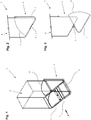
- Figure 1 shows a collecting container 1 for a sorting system according to the prior art with an inlet opening 2 and a removal device 3.
- the sorted objects are transported into the interior of the collecting container 1 where they are stored or kept until they are removed by the user of the sorting system.
- the removal device 3 has a flap 4, which is rotatably supported by a hinge as a rotation axis 5 and can be pivoted downward in order to release the contents of the collecting container 1.
- Two side walls 6 serve as a flush seal for the safe and targeted discharge of the collecting container 1.
- the side walls 6 of the flap 4 could also be on the inside, but then a deflecting element above the side walls 6 of the flap 4 would be necessary so that the sorted objects fall down or the removal device 3 cannot jam.
- FIG. 2 The displayed viewing direction in Figure 1 on the side of the bin 1 is in Figure 2 shown.
- the removal device 3 of the collecting container 1 is in the closed position.
- the axis of rotation 5 runs in Figure 2 perpendicular through the image plane and is indicated by a crosshair.
- the hinge is riveted to the collecting container 1 on the one hand and to the flap 4 on the other hand.
- a locking mechanism which the flap 4 in the closed Holds position and prevents the flap 4 from swiveling down unintentionally.
- Such a locking mechanism can be a simple rotary or sliding button with a locking tab, as well as a rotary or sliding lock, which additionally prevents unauthorized access to the sorted out objects.
- FIG Figure 3 The open removal device 3 of the collecting container 1 according to the prior art is shown in FIG Figure 3 shown.
- the flap 4 is pivoted downward about the axis of rotation 5 and releases the contents of the collecting container 1 for emptying. Since the flap pivots freely down into the open position, individual removal of objects is difficult.
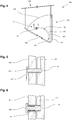
- Figure 4 shows a first embodiment of an inventive collecting container 101.
- a guide track 107 in Figure 4 (and in the further Figures 7 , 10th , 11 and 12 ) drawn as a dash-dotted line and let into the side of the collecting container 101 facing the viewer as a blind hole groove 111 in the shape of a segment of a circle.
- the circle segment describing the blind hole groove 111 has the center of the circle congruent with the axis of rotation 105.
- Such a blind hole groove 111 can also be present on the opposite side of the collecting container 101.
- a latching bolt 108 passed through a hole in the side wall 106 (see Figures 5 and 6 ) engages in this blind hole 111 and guides the flap 104 along the guide track 107.
- the fastening of the locking bolt 108 is realized here by a tab attached to the side wall 106 as a spring element 117, although other types of fastening of the locking bolt 108 not described here would also be possible .
- the section view CC from Figure 4 is in Figure 5 shown enlarged.
- the locking bolt 108 is passed through a through hole in the side wall 106 and engages in the blind hole 111 and lies in the recess at the bottom of the blind hole 111, which at the same time corresponds to the end position 114 when the removal device 103 is closed. If the flap 104 is now pivoted downwards or the removal device 103 is opened, the locking bolt 108 is pressed on the recess at the bottom of the blind hole 111, bends the tab, which acts as a spring element 117, and guides the flap 104 along the guide track 107 ( Not shown).
- FIG 6 is another option for the latching mechanism Figure 5 shown.
- the locking bolt 108 is pressed against the bottom of the blind hole 111 by a spiral spring as a spring element 117.
- Figure 7 represents a second possible embodiment of the inventive collecting container 201.
- the guide track 207 is attached to the side wall 206 of the flap 204 as a through groove 211.
- the locking bolt 208 fixedly attached to the side wall of the collecting container 201 holds the flap 204 in the end position 214 in which the removal device 203 is closed.
- the locking mechanism to the in Figure 7 second embodiment shown is in Figure 8 shown enlarged. Due to the larger diameter of the head part of the locking bolt 208, matching a through hole which has a larger diameter than the width of the through groove 211, the flap 204 is held in the end position 215 in a form-fitting manner.
- the locking bolt 208 is unlocked by pulling it out (in Figure 8 from the viewer's point of view, to the left).
- the spring element 217 shown here as a spiral spring, is thereby compressed and pretensioned.
- the narrower neck portion of the locking bolt 208 is dimensioned so that the locking bolt 208 can be guided freely along the through groove 211.
- FIG Figure 9 A third embodiment of an inventive collecting container 301 is shown in isometric view in FIG Figure 9 shown.
- the hinge 318 connects the collecting container 301 to the flap 304, and at the same time forms the axis of rotation 305.
- One hinge leg of the hinge 318 is rigidly connected to the flap 304, and the other hinge leg is linear with the collecting container 301 through two elongated holes 312 in its longitudinal direction slidably connected.
- the Figure 10 shows the third embodiment of an inventive collecting container 301 in the side view from viewing direction B (see Figure 9 ) with the removal device 303 closed.
- the guide track 307 attached to at least one side wall 306 of the flap 304 is divided into a first circular segment 309 'and a second circular segment 309 ".
- the circular segments 309', 309" each have a different radius, but both have the same center of the circle, which is also the axis of rotation 305.
- the guide track 307 designed as a through groove 311 is cranked or stepped due to the two-part segmentation and is thus connected to one another.
- Figure 11 is the third embodiment of an inventive collecting container 301 in the side view from viewing direction B (see Figure 9 ) is shown with the removal device 303 open in an intermediate position in which sorted objects can be individually removed.
- the guide pin 308 is now in the intermediate position 316. Due to the offset d, formed by the two-part segmentation of the guide track 307, the through groove 311 has a support shoulder, whereupon the flap 304 is held in its position. In this intermediate position 316, one or more rejected objects can now be easily removed from the removal device 303.
- the hinge 318 forming the axis of rotation 305 together with the flap 304 and the side walls 306 attached to it are offset by the offset d in the direction of the elongated holes 312 (see FIG Figure 9 ) postponed.
- the guide pin 308 reaches the guide track 307 formed by the second circular segment 309 ′′.
- the flap 304 can now be rotated further about the axis of rotation 305 up to the end position 315.
- the guideway 107, 207 must be equipped with additional intermediate positions. In the case of the first exemplary embodiment, this means that further depressions would have to be created at the base of the blind hole groove 111 or, in the case of the second exemplary embodiment, that further through holes would have to be created. In the case of the third embodiment, further circular segments would have to be added to the guideway 307.
- the side walls 106, 206, 306 are each attached to the outside of the collecting container 101, 201, 301.
- each embodiment can also be designed with internal side walls 106, 206, 306. All that is required is a kinematic reversal of the functional units of the guide element 110, 210, 310.
Landscapes
- Physics & Mathematics (AREA)
- General Physics & Mathematics (AREA)
- Engineering & Computer Science (AREA)
- Mechanical Engineering (AREA)
- Sorting Of Articles (AREA)
- Warehouses Or Storage Devices (AREA)
- Refuse Receptacles (AREA)
- Sampling And Sample Adjustment (AREA)
Description
- Die Erfindung betrifft eine Vorrichtung zum Entleeren eines Auffangbehälters für eine Aussortieranlage zur Speicherung aussortierter Gegenstände an einem Produktkontrollsystem, insbesondere einer Kontrollwaage und/oder eines Metalldetektionssystems und/oder eines Inspektionsgeräts basierend auf elektromagnetischer Strahlung.
- In der Herstellung von pharmazeutischen oder kosmetischen Produkten, Lebensmitteln, Getränken sowie in der Logistik-, chemischen, Automobilzuliefer-, und der metallverarbeitenden Industrie sind Kontrollwaagen ein Schlüsselelement der Qualitätssicherung. Sie verbessern nicht nur die Ausschöpfung der vorhandenen Ressourcen, sondern helfen auch nationale Verordnungen, Eichvorschriften und Industrienormen zu erfüllen. Ein effektives Kontrollwägesystem bietet Schutz gegen Produktfehler und senkt die Gesamtbetriebskosten.
- Eine dynamische Kontrollwaage ist ein System, das Wägegüter verwiegt, während sie innerhalb einer Produktionslinie über die Waage geführt werden, die Wägegüter in vorgegebene Gewichtszonen klassiert und die Wägegüter entsprechend der Gewichtsklassierung sortiert oder ausschleust. Einsatzgebiete von Kontrollwaagen sind vielseitig und umfassen zum Beispiel:
- Prüfung auf Unter- bzw. Übergewicht von Produkten
- Einhaltung der gesetzlichen Bestimmungen für den Nettoinhalt von verpackten Gütern
- Reduzierung von Produktverschwendungen durch Verwendung der mittels der Kontrollwaage gewonnenen Gewichtswerte zur Einstellung der Füllmaschinen
- Klassierung von Produkten nach Gewicht
- Messung und Aufzeichnung der Leistung der Produktionsanlage bzw. -linie
- Stückzahl-Verifizierung anhand des Gewichts
Mit Kontrollwaagen werden 100% der Produkte einer Produktlinie gewogen. So werden dann auch die gesamten Produktionsdaten gesammelt für Produktzählung, Chargennachverfolgung oder für die Produktionsstatistik. - Ein Kontrollwägesystem besteht üblicherweise aus Zuführband, Wägeband, Abführband mit Sortiereinrichtung und Wägeterminal mit Benutzerschnittstelle. Das zwischen Zu- und Abführband gelegene Wägeband ist üblicherweise auf einer Wägezelle gelagert, welche das Gewicht des Produkts beim Überfahren des Wägebandes dynamisch erfasst. Die zwei am häufigsten verwendeten Wägetechnologien für Kontrollwaagen sind Wägezellen mit Dehnungsmessstreifen (DMS) oder nach dem Prinzip der elektromagnetischen Kraftkompensation (EMFR) arbeitende Wägezellen. Nach ihrem Transport über das Wägeband werden die Produkte von einem dem Wägeband nachgeschalteten Abführband abtransportiert. Durch die dynamische Wägung werden fehlgewichtige Produkte erkannt und von einer Sortiervorrichtung in der Regel quer zu dem in der Längsrichtung stattfindenden Transport der Produkte ausgestossen.
- Ebenso wie Kontrollwaagen gehören auch Metalldetektoren zu den Schlüsselkomponenten für eine effektive Qualitätssicherung. Der Einsatz von Metalldetektoren wird von gewerblichen Nutzern für die Suche nach Produktverunreinigungen eingesetzt, beispielsweise für die Suche nach Bleikugeln in Fleisch, Drahtteilen in Getreide, Spänen aufgrund von Reparaturen an der Produktionsanlage oder sonstigen Verunreinigungen aus der Produktverarbeitung.
- Bei einem industriellen Metalldetektionssystem handelt es sich um ein hoch entwickeltes Gerät, mit dem metallische Fremdkörper erkannt und aussortiert werden können. Die Detektierbarkeit schliesst eisenhaltige Metalle, auch Edelstähle und nichteisenhaltige Metalle, wie Messing, Kupfer, Aluminium und Blei, ein. Ein typisches Metalldetektionssystem besteht aus folgenden vier Hauptkomponenten: Suchkopf, Transportsystem, Bedieneinheit und automatische Sortiereinheit. Der Suchkopf besteht dabei aus meist mehreren elektromagnetischen Spulen, welche zur Detektion hochfrequente elektromagnetische Felder erzeugen bzw. empfangen.
- Eine automatisierte Sortiereinheit hat die Aufgabe jene Produkte aus dem Produktestrom auszusortieren, welche bei einer vorgängigen Produkteprüfung die vom Benutzer festgelegten Qualitätsmerkmale nicht erfüllten. Die Aussortierung kann auf verschiedenste Arten erfolgen und ist auch vom auszusortierenden Produkt abhängig. Leichte Produkte, wie zum Beispiel Siegelrandbeutel, können durch einen Luftstoss aus einer Luftdüse aus dem Produktestrom entfernt werden. Viel häufiger wird jedoch das fehlerhafte Produkt durch eine Ausstosseinheit entfernt, welche mechanisch durch einen Kolbenzylinder oder mittels eines Elektromotors angetrieben wird.
- Das vom originären Produktestrom ausgeschiedene Produkt gelangt dann entweder auf eine weitere Förderstrasse und wird vom Produktstrom entfernt, oder wird direkt beim Produktstrom in einen Auffangbehälter befördert. Im Auffangbehälter sammeln sich demnach alle fehlerhaften Produkte eines Kontrollsystems. Der Betreiber des Kontrollsystems hat nun die Möglichkeit die Produkte auf deren Fehler genauer zu kontrollieren, indem er diese Produkte dem Auffangbehälter entnimmt.
- In
DE 3 333 316 A1 ist ein Altrohstoffsammelbehälter zur besseren Altrohstoffsammlung mit einer Kipplade und einem Deckel gezeigt. Die Kipplade wird mittels zwei eine Drehachse bildende Drehzapfen in die bodennahe Führung eingeführt. Zwei Stifte begrenzen als Ausschwenkanschlag das Ausschwenken der Kipplade. Diese Ausführung eines Behälters ist nicht geeignet für die Verwendung als Auffangbehälter an einer Aussortieranlage, denn die Entnahme der sich im Inneren befindlichen Gegenstände erfolgt durch die gleiche Öffnung wie die Zufuhr. Hinzu kommt, dass der Behälter nicht dafür ausgelegt ist während einer Entnahme weitere aussortierte Gegenstände aufzunehmen. An einer automatisierten Produktionsanlage mit einer Aussortieranlage ist dies zwingend nötig, da sonst die Aussortierung unterbrochen werden müsste. - Weitere Abfallbehälter mit einer Einlassöffnung und einer separaten Entnahmeeinrichtung sind aus der
US 6,202,922 B1 , derUS 5,361,978 A , und derUS 814,563 A bekannt. Alle Abfallbehälter haben gemeinsam, dass die jeweilige Entnahmeeinrichtung in nur zwei Positionen verharren kann, nämlich in der geschlossenen und der vollständig geöffneten Position. -
DE 10 2004 032 052 A1 offenbart einen Transportbehälter, welcher von oben durch die Deckelöffnung mit Tabak befüllt und bei Erreichen seines Bestimmungsortes durch die Bodenöffnung entleert wird. Die Bodenöffnung ist durch einen in einer Führungseinrichtung schiebbar geführten Riegel schliess- und öffenbar. - In
US 2004 130 247 A1 ist ein Kipporganisator gezeigt mit einem Basisabschnitt und einem Versorgungsabschnitt, der beweglich mit dem Basisabschnitt verbunden ist. Der Basisabschnitt ist eine einzelne Einheit, die keine beweglichen Teile hat und mindestens eine Seitenwand mit einer darin ausgebildeten Nut aufweist. Der Zuführabschnitt ist eine einzelne Einheit, die keine beweglichen Teile aufweist und eine Vielzahl von darin zur Lagerung ausgebildeten Abteilen und einen Arm aufweist, der in einer äußeren Seitenwand zum beweglichen Eingriff mit der Nut ausgebildet ist. Wenn sich der Arm in der Nut bewegt, bewegt sich der Zufuhrabschnitt innerhalb des Basisabschnitts. Der Zufuhrabschnitt kann sich vom Basisabschnitt erstrecken und neigen, um eine aktuelle Ansicht und einen Zugang zu den Abteilen zu bieten. - Ein von der Anmelderin bereits vertriebener Auffangbehälter für eine Montage an einer Aussortieranlage weist auf Höhe des Abführbandes eine Einlassöffnung auf und eine dem Untergrund nähere Entnahmeeinrichtung auf. Die Entnahmeeinrichtung ist durch eine nach unten schwenkbare Klappe realisiert. Dabei kann die Klappe zwei Positionen einnehmen: Eine in welcher der Auffangbehälter geschlossen ist und eine in welcher der gesamte Inhalt des Auffangbehälters entleert werden kann. Es hat sich gezeigt, dass eine Einzelentnahme eines aussortierten Gegenstandes sich schwierig gestaltet, da die Klappe nach der Öffnung nach unten abschwenkt und alle im Inneren befindlichen Gegenstände herausfallen können.
- Aufgabe der Erfindung ist es, einen Auffangbehälter für eine Aussortieranlage zu schaffen bei welchem eine Einzelentnahme auf einfache Art und Weise möglich ist, d.h. die Handhabung zur Entnahme soll bevorzugt einhändig erfolgen.
- Weiter soll es möglich sein, dass die Aussortieranlage während der Entnahme nicht gestoppt werden muss und weitere Gegenstände, welche aussortiert werden sollen in den Auffangbehälter gefördert werden können.
- Die Aufgabe wird dadurch gelöst, dass der Auffangbehälter für eine Aussortieranlage zur Lagerung aussortierter Gegenstände eine für die Zuführung aussortierter Gegenstände in das Innere des Auffangbehälters ausgebildete Einlassöffnung und eine für die Entnahme eines oder mehrerer aussortierter Gegenstände aus dem Inneren des Auffangbehälters ausgebildete und in der Regel unterhalb der Einlassöffnung angeordnete Entnahmeeinrichtung aufweist. Die Entnahmeeinrichtung weist eine Klappe auf, welche um eine Drehachse drehbar gelagert ist. Weiter weist die Entnahmeeinrichtung zwei seitlich an der Klappe angebrachte Seitenwände auf.
- Die Erfindung ist durch den Gegenstand des unabhängigen Anspruchs 1 und der abhängigen Ansprüche 2-12 gekennzeichnet, wobei der Auffangbehälter eine Führungseinrichtung, mit mindestens einer Führungsbahn und mindestens einen im Betrieb des Auffangbehälters in die Führungsbahn eingreifenden Bolzen, aufweist. Dabei ist die Führungsbahn entweder an einer Seitenwand der Klappe oder an der Seite des Auffangbehälters und der Bolzen entsprechend gegenüberliegend an der Seite des Auffangbehälters oder an der Seitenwand der Klappe angeordnet.
- Wobei die Führungsbahn zwei Endpositionen und mindestens eine zwischen den Endpositionen liegende Zwischenposition aufweist, wobei der Bolzen als Rastbolzen ausgebildet ist und jeweils an der Zwischenposition beziehungsweise an beiden Endpositionen einrastbar ist.
- Durch die Zwischenposition ist es möglich die Klappe des Auffangbehälters in einer halboffenen Position zu belassen um aussortierte Gegenstände einzeln aus dem Auffangbehälter zu entnehmen. Ein weiterer Vorteil dabei ist, dass dies mit nur einer Hand gemacht werden kann.
- Eine vorteilhafte Weiterbildung der Erfindung sieht vor, dass die Führungsbahn kreissegmentförmig ist, wobei die Drehachse den Kreismittelpunkt bildet.
- Eine weitere Ausgestaltung der Erfindung sieht vor, dass die Rastbolzen durch ein Federelement vorgespannt in die Führungsbahn hineingedrückt werden.
- Eine weitere vorteilhafte Ausgestaltung der Erfindung sieht vor, dass die Führungsbahn als Sacklochnut ausgebildet ist und die Rastpunkte der Führungsbahn jeweils als Vertiefung in der Sacklochnut ausgebildet sind.
- In einer bevorzugten Ausführungsform der Erfindung ist die Führungsbahn als eine durch die Dicke der Seitenwand durchgehende Durchgangsnut ausgebildet und die Rastpunkte der Führungsbahn sind als Durchgangsloch ausgebildet, wobei der Durchmesser des Durchgangslochs grösser ist als die Breite der Durchgangsnut.
- In einer weiteren bevorzugten Ausführungsform der Erfindung lässt sich die Drehachse rechtwinklig zu sich selbst linear verschieben. Die Führungsbahn weist ein erstes Kreissegment und ein zweites Kreissegment auf, welche miteinander verbunden sind und unterschiedliche Radien aufweisen, wobei die Drehachse den Mittelpunkt des ersten Kreissegments und des zweiten Kreissegments bildet, und der Bolzen als Führungsbolzen ausgebildet sind.
- Ein Vorteil dieser Ausführungsform ist, dass dabei nur ein minimaler Verschleiss an dem Bolzen auftritt. Dies führt auch zu einer verminderten Geräuschentwicklung für eine in Bewegung befindliche Klappe.
- Eine Weiterbildung einer Ausführungsform der Erfindung sieht vor, dass die Führungsbahn als eine durch die Dicke der Seitenwand der Klappe oder durch die Dicke der Seite des Auffangbehälters durchgehende Durchgangsnut ausgebildet ist.
- Eine weitere Weiterbildung einer Ausführungsform der Erfindung sieht vor, dass sich die Drehachse rechtwinklig zu sich selbst linear um 10 - 15mm verschieben lässt, wobei sich zugleich der Führungsbolzen auf der Führungsbahn vom ersten Kreissegment auf das zweite Kreissegment verschiebt.
- Eine weitere vorteilhafte Weiterbildung einer Ausführungsform der Erfindung sieht vor, dass die Drehachse als ein Scharnier ausgebildet ist, wobei der eine Scharnierschenkel mit der Klappe starr verbunden ist und der andere Scharnierschenkel mit dem Auffangbehälter durch mindestens zwei Langlöcher in deren Richtung linear verschiebbar verbunden ist.
- In einer vorteilhaften Ausgestaltung beträgt der Winkel zwischen der Endposition in welcher die Entnahmeeinrichtung geschlossen ist und der mindestens einen Zwischenposition 40° - 70°.
- In einer weiteren vorteilhaften Ausgestaltung beträgt der Winkel zwischen der mindestens einen Zwischenposition und der Endposition in welcher die Entnahmeeinrichtung geöffnet ist 60° - 90°.
- In einer weiteren Ausgestaltung erstreckt sich die gesamte Führungsbahn über einen Winkel zwischen 100° - 160°.
- In einer Inspektionsanlage insbesondere aufweisend eine Kontrollwaage und/oder ein Metalldetektionssystem und/oder ein Inspektionsgerät basierend auf elektromagnetischer Strahlung ist/sind ein oder mehrere Auffangbehälter vorhanden.
- Einzelheiten des erfindungsgemässen Auffangbehälters ergeben sich anhand der Beschreibung der in den Zeichnungen dargestellten Ausführungsbeispiele. Es zeigen:
- Fig. 1
- Auffangbehälter nach Stand der Technik in einer isometrischen Ansicht;
- Fig. 2
- Auffangbehälter nach Stand der Technik als Seitenansicht aus Blickrichtung A gemäss
Figur 1 auf die geschlossene Entnahmeeinrichtung eines Auffangbehälters nach Stand der Technik; - Fig. 3
- Auffangbehälter nach Stand der Technik als Seitenansicht aus Blickrichtung A gemäss
Figur 1 auf die geöffnete Entnahmeeinrichtung eines Auffangbehälters nach Stand der Technik; - Fig. 4
- Seitliche Ansicht eines ersten Ausführungsbeispiels eines erfinderischen Auffangbehälters;
- Fig. 5
- Einrastmechanismus des ersten Ausführungsbeispiels eines erfinderischen Auffangbehälters durch die Schnittlinie C-C aus
Fig. 4 ; - Fig. 6
- Weitere Ausführungsmöglichkeit des Einrastmechanismus für ein erstes Ausführungsbeispiel eines erfinderischen Auffangbehälters;
- Fig. 7
- Seitliche Ansicht eines zweiten Ausführungsbeispiels eines erfinderischen Auffangbehälters;
- Fig. 8
- Einrastmechanismus des zweiten Ausführungsbeispiels eines erfinderischen Auffangbehälters gemäss Schnittansicht D-D aus
Fig. 7 - Fig. 9
- Isometrische Ansicht eines dritten Ausführungsbeispiels eines erfinderischen Auffangbehälters;
- Fig. 10
- Seitenansicht des dritten Ausführungsbeispiels eines erfinderischen Auffangbehälters aus Blickrichtung B auf die geschlossene Entnahmeeinrichtung;
- Fig. 11
- Seitenansicht des dritten Ausführungsbeispiels eines erfinderischen Auffangbehälters aus Blickrichtung B auf die geöffnete Entnahmeeinrichtung in einer Zwischenstellung, in welcher aussortierte Gegenstände einzeln entnehmbar sind;
- Fig. 12
- Seitenansicht des dritten Ausführungsbeispiels eines erfinderischen Auffangbehälters aus Blickrichtung B auf die voll geöffnete Entnahmeeinrichtung.
-
Figur 1 zeigt einen Auffangbehälter 1 für eine Aussortieranlage nach Stand der Technik mit einer Einlassöffung 2 und einer Entnahmeeinrichtung 3. Die aussortierten Gegenstände werden in das Innere des Auffangbehälters 1 befördert wo sie bis zur Entnahme durch den Benutzer der Aussortieranlage gelagert bzw. aufbewahrt werden. Die Entnahmeeinrichtung 3 weist eine Klappe 4 auf, welche durch ein Scharnier als Drehachse 5 drehbar gelagert ist und nach unten geschwenkt werden kann, um den Inhalt des Auffangbehälters 1 freizugeben. Zwei Seitenwände 6 dienen als bündigen Abschluss zur sicheren und gezielten Ausschüttung des Auffangbehälters 1. Die Seitenwände 6 der Klappe 4 könnten auch innenliegend sein, jedoch wäre dann ein Ablenkelement oberhalb der Seitenwände 6 der Klappe 4 nötig, damit die aussortierten Gegenstände bis nach unten fallen bzw. die Entnahmeeinrichtung 3 nicht verklemmen können. - Die angezeigte Blickrichtung in
Figur 1 auf die Seite des Auffangbehälters 1 ist inFigur 2 dargestellt. Die Entnahmeeinrichtung 3 des Auffangbehälters 1 ist dabei in der geschlossenen Position. Die Drehachse 5 verläuft inFigur 2 senkrecht durch die Bildebene und ist durch ein Fadenkreuz gekennzeichnet. Das Scharnier ist einerseits am Auffangbehälter 1 und andererseits an der Klappe 4 angenietet. Nicht gezeigt inFigur 2 ist ein Verriegelungsmechanismus, welcher die Klappe 4 in der geschlossenen Position hält und verhindert, dass die Klappe 4 unbeabsichtigt nach unten schwenkt. Ein solcher Verriegelungsmechanismus kann sowohl ein einfacher Dreh- oder Schiebeknopf mit einer Verriegelungslasche sein, als auch ein Dreh- oder Schiebeschloss, welches zusätzlich den unbefugten Zugriff auf die aussortierten Gegenstände verhindert. - Die offene Entnahmeeinrichtung 3 des Auffangbehälters 1 nach Stand der Technik wird in
Figur 3 gezeigt. Die Klappe 4 ist um die Drehachse 5 nach unten geschwenkt und gibt den Inhalt des Auffangbehälters 1 frei zur Entleerung. Da die Klappe frei nach unten in die offene Position schwenkt gestaltet sich eine Einzelentnahme von Gegenständen schwierig. -
Figur 4 zeigt ein erstes Ausführungsbeispiel eines erfinderischen Auffangbehälters 101. Als Teil eines Führungselementes 110 ist eine Führungsbahn 107, inFigur 4 (und in den weiterenFiguren 7 ,10 ,11 und 12 ) als strichpunktierte Linie gezeichnet und als kreissegmentförmige Sacklochnut 111 in die dem Betrachter zugewandte Seite des Auffangbehälters 101 eingelassen. Das die Sacklochnut 111 beschreibende Kreissegment hat dabei den Kreismittelpunkt deckungsgleich mit der Drehachse 105. Auf der abgewandten Seite des Auffangbehälters 101 kann ebenso eine solche Sacklochnut 111 vorhanden sein. Ein durch ein Loch in der Seitenwand 106 hindurchgeführter Rastbolzen 108 (sieheFig. 5 und 6 ) greift in diese Sacklochnut 111 ein und führt die Klappe 104 entlang der Führungsbahn 107. Die Befestigung des Rastbolzens 108 ist hier durch eine an der Seitenwand 106 angebrachte Lasche als Federelement 117 realisiert, wobei auch andere hier nicht weiter beschriebene Befestigungsarten des Rastbolzens 108 möglich wären. Entlang der Führungsbahn 107 sind zwei Endpositionen 114, 115 und eine Zwischenposition 116 vorhanden, welche jeweils als eine Vertiefung am Grund der Sacklochnut 111 ausgebildet sind. - Die Schnittansicht C-C aus
Figur 4 wird inFigur 5 vergrössert dargestellt. Durch ein Durchgangsloch in der Seitenwand 106 ist der Rastbolzen 108 hindurchgeführt und greift in die Sacklochnut 111 ein und liegt in der Vertiefung am Grund der Sacklochnut 111, was zugleich der Endposition 114 bei geschlossener Entnahmeeinrichtung 103 entspricht. Wird nun die Klappe 104 nach unten geschwenkt bzw. die Entnahmeeinrichtung 103 geöffnet, so wird der Rastbolzen 108 auf der Vertiefung am Grund der Sacklochnut 111 gedrückt, verbiegt die Lasche, welche als Federelement 117 wirkt, und führt die Klappe 104 entlang der Führungsbahn 107 (nicht gezeigt). - In
Figur 6 wird eine weitere Ausführungsmöglichkeit des Einrastmechanismus ausFigur 5 gezeigt. Der Rastbolzen 108 wird hierbei durch eine Spiralfeder als Federelement 117 an den Grund der Sacklochnut 111 gedrückt. -
Figur 7 stellt eine zweite Ausführungsmöglichkeit des erfinderischen Auffangbehälters 201 dar. Die Führungsbahn 207 ist dabei als Durchgangsnut 211 an der Seitenwand 206 der Klappe 204 angebracht. Der fix an der Seitenwand des Auffangbehälters 201 angebrachte Rastbolzen 208 hält die Klappe 204 in der Endposition 214 in welcher die Entnahmeeinrichtung 203 geschlossen ist. - Der Einrastmechanismus zu dem in
Figur 7 gezeigten zweiten Ausführungsbeispiels ist inFigur 8 vergrössert dargestellt. Durch den grösseren Durchmesser der Kopfpartie des Rastbolzens 208, passend zu einem Durchgangsloch, welches einen grösseren Durchmesser aufweist als die Breite der Durchgangsnut 211 wird die Klappe 204 formschlüssig in der Endposition 215 gehalten. Entriegelt wird der Rastbolzen 208 indem man diesen herauszieht (inFigur 8 aus Sicht des Betrachters, nach links). Das Federelement 217, hier als Spiralfeder dargestellt, wird dabei zusammengedrückt und vorgespannt. Die schmälere Halspartie des Rastbolzens 208 ist dabei so dimensioniert, dass der Rastbolzen 208 frei entlang der Durchgangsnut 211 geführt werden kann. - Ein drittes Ausführungsbeispiel eines erfinderischen Auffangbehälters 301 ist in isometrischer Ansicht in
Figur 9 gezeigt. Das Scharnier 318 verbindet den Auffangbehälter 301 mit der Klappe 304, und bildet zugleich die Drehachse 305. Der eine Scharnierschenkel des Scharniers 318 ist mit der Klappe 304 starr verbunden, und der andere Scharnierschenkel ist mit dem Auffangbehälter 301 durch zwei Langlöcher 312 in deren Längsrichtung linear verschiebbar verbunden. - Die
Figur 10 stellt das dritte Ausführungsbeispiel eines erfinderischen Auffangbehälters 301 in der Seitenansicht aus Blickrichtung B (sieheFigur 9 ) bei geschlossener Entnahmeeinrichtung 303 dar. Die an mindestens eine Seitenwand 306 der Klappe 304 angebrachte Führungsbahn 307 ist in ein erstes Kreissegment 309' und ein zweites Kreissegment 309" aufgeteilt. Die Kreissegmente 309', 309" haben jeweils einen unterschiedlichen Radius, jedoch haben beide den selbigen Kreismittelpunkt, welcher zugleich die Drehachse 305 ist. Die als Durchgangsnut 311 ausgebildete Führungsbahn 307 ist durch die zweiteilige Segmentierung gekröpft bzw. abgestuft und somit miteinander verbunden. - In
Figur 11 ist das dritte Ausführungsbeispiel eines erfinderischen Auffangbehälters 301 in der Seitenansicht aus Blickrichtung B (sieheFigur 9 ) bei geöffneter Entnahmeeinrichtung 303 in einer Zwischenstellung, in welcher aussortierte Gegenstände einzeln entnehmbar sind, dargestellt. Der Führungsbolzen 308 befindet sich nun in der Zwischenposition 316. Durch den Versatz d, gebildet durch die zweiteilige Segmentierung der Führungsbahn 307, weist die Durchgangsnut 311 eine Auflageschulter auf, worauf die Klappe 304 in ihrer Position gehalten wird. Es kann nun in dieser Zwischenposition 316 auf einfache Weise ein oder mehrere aussortierte Gegenstände aus der Entnahmeeinrichtung 303 entnommen werden. - Um die Entnahmeeinrichtung 303 vollständig zu öffnen, wie es in
Figur 12 gezeigt ist, wird das die Drehachse 305 bildende Scharnier 318 samt der Klappe 304 und den daran angebrachten Seitenwänden 306 um den Versatz d in Richtung der Langlöcher 312 (sieheFigur 9 ) verschoben. Der Führungsbolzen 308 gelangt auf die durch das zweite Kreissegment 309" gebildete Führungsbahn 307. Die Klappe 304 kann nun bis zur Endposition 315 weiter um die Drehachse 305 gedreht werden. - Soll die Klappe 304 an weiteren Positionen gehalten werden können, so ist die Führungsbahn 107, 207 mit zusätzlichen Zwischenpositionen auszustatten. Dies heisst im Falle des ersten Ausführungsbeispiels, dass weitere Vertiefungen am Grund der Sacklochnut 111 oder im Falle des zweiten Ausführungsbeispiels, dass weitere Durchgangslöcher geschaffen werden müssten. Im Falle der dritten Ausführungsform müssten der Führungsbahn 307 weitere Kreissegmente hinzugefügt werden.
- In allen beschriebenen Ausführungsbeispielen des erfindungsgemässen Auffangbehälters 101, 201, 301 sind die Seitenwände 106, 206, 306 jeweils aussenliegend am Auffangbehälter 101, 201, 301 angebracht. Jede Ausführungsform kann aber auch mit innenliegenden Seitenwänden 106, 206, 306 ausgeführt werden. Dazu bedarf es lediglich einer kinematischen Umkehr der Funktionseinheiten des Führungselements 110, 210, 310.
- Obwohl die Erfindung durch die Darstellung von mehreren spezifischen Ausführungsbeispielen beschrieben worden ist, ist es offensichtlich, dass zahlreiche weitere Ausführungsvarianten in Kenntnis der vorliegenden Erfindung geschaffen werden können, beispielsweise indem die Merkmale der einzelnen Ausführungsbeispiele miteinander kombiniert und/oder einzelne Funktionseinheiten der Ausführungsbeispiele ausgetauscht werden.
-
- 1, 101, 201, 301
- Auffangbehälter
- 2, 102, 202, 302
- Einlassöffnung
- 3, 103, 203, 303
- Entnahmeeinrichtung
- 4, 104, 204, 304
- Klappe
- 5,105, 205, 305
- Drehachse
- 6, 106, 206, 306
- Seitenwand
- 107,207,307
- Führungsbahn
- 108, 208
- Rastbolzen
- 308
- Führungsbolzen
- 109, 209
- Kreissegment
- 309'
- Erstes Kreissegment
- 309"
- Zweites Kreissegment
- 110, 210, 310
- Führungseinrichtung
- 111,
- Sacklochnut
- 211, 311
- Durchgangsnut
- 312
- Langloch
- 114, 214, 314
- Endposition bei geschlossener Entnahmeeinrichtung (103, 203, 303)
- 115, 215, 315
- Endposition bei geöffneter Entnahmeeinrichtung (103, 203, 303)
- 116, 216, 316
- Zwischenposition
- 117, 217
- Federelement
- 318
- Scharnier
- d
- Versatz
Claims (12)
- Auffangbehälter (101, 201, 301) für eine Aussortieranlage zur Lagerung aussortierter Gegenstände aufweisend eine für die Zuführung aussortierter Gegenstände in das Innere des Auffangbehälters (101, 201, 301) ausgebildete Einlassöffnung (102, 202, 302) und eine für die Entnahme eines oder mehrerer aussortierter Gegenstände aus dem Inneren des Auffangbehälters (101, 201, 301) ausgebildete Entnahmeeinrichtung (103, 203, 303) aufweisend eine Klappe (104, 204, 304), welche um eine Drehachse (105, 205, 305) drehbar gelagert ist, und zwei seitlich an der Klappe (104, 204, 304) angebrachte Seitenwände (106, 206, 306)
dadurch gekennzeichnet, dassder Auffangbehälter (101, 201) eine Führungseinrichtung (110, 210), mit mindestens einer Führungsbahn (107, 207) und mindestens einen im Betrieb des Auffangbehälters (101, 201) in die Führungsbahn (107, 207) eingreifenden Bolzen (108, 208) aufweist, wobei die Führungsbahn (107, 207) entweder an einer Seitenwand (6) der Klappe (104, 204) oder an der Seite des Auffangbehälters (101, 201) und der Bolzen (108, 208) entsprechend gegenüberliegend an der Seite des Auffangbehälters (101, 201) oder an der Seitenwand (106, 206) der Klappe (104, 204) angeordnet ist, unddass die Führungsbahn (107, 207) zwei Endpositionen (114, 115, 214, 215) und mindestens eine zwischen den Endpositionen (114, 115, 214, 215) liegende Zwischenposition (116, 216) aufweist, welche jeweils als eine Vertiefung am Grund der Führungsbahn (107) oder die als Durchgangslöcher ausgebildet sind, wobei der jeweilige Durchmesser eines Durchgangslochs grösser ist als die Breite der Führungsbahn (207), oder dassder Auffangbehälter (301) eine Führungseinrichtung (310), mit mindestens einer Führungsbahn (307) und mindestens einen im Betrieb des Auffangbehälters (301) in die Führungsbahn (307) eingreifenden Bolzen (108, 208, 308) aufweist, wobei die Führungsbahn (307) an einer Seitenwand (306) der Klappe (304) und der Bolzen (308) gegenüberliegend an der Seite des Auffangbehälters (301) angeordnet ist,dass sich die Drehachse (305) rechtwinklig zu sich selbst linear verschieben lässt, unddass die Führungsbahn (307) ein erstes Kreissegment (309') und ein zweites Kreissegment (309") aufweist, welche miteinander verbunden sind, dabei eine Zwischenposition (316) bilden und unterschiedliche Radien aufweisen, wobei die Drehachse (305) den Mittelpunkt des ersten Kreissegments (309') und des zweiten Kreissegments (309") bildet, und der Bolzen als Führungsbolzen (308) ausgebildet ist. - Auffangbehälter nach einem der Ansprüche 1 dadurch gekennzeichnet, dass
die Führungsbahn (107, 207) kreissegmentförmig ist, wobei die Drehachse (105, 205) den Kreismittelpunkt bildet. - Auffangbehälter nach einem der Ansprüche 1 oder 2 dadurch gekennzeichnet, dass
der Bolzen als Rastbolzen (108, 208) ausgebildet ist und jeweils an der Zwischenposition (116, 216) und an beiden Endpositionen (114, 115, 214, 215) einrastbar ist. - Auffangbehälter nach Anspruch 3 dadurch gekennzeichnet, dass
der Rastbolzen (108, 208) durch ein Federelement (117, 217) vorgespannt in die Führungsbahn (107, 207) hineingedrückt wird. - Auffangbehälter nach Anspruch 1 dadurch gekennzeichnet, dass
die Führungsbahn (207, 307) als eine durch die Dicke der Seitenwand (206, 306) der Klappe (204, 304) oder durch die Dicke der Seite des Auffangbehälters (201) durchgehende Durchgangsnut (211, 311) ausgebildet ist. - Auffangbehälter nach einem der Ansprüche 1 bis 5 dadurch gekennzeichnet, dass
die Führungsbahn (107, 307) als Sacklochnut (111) an der Seitenwand (106, 306) der Klappe (104, 304) oder an der Seite des Auffangbehälters (101) ausgebildet ist. - Auffangbehälter nach einem der Ansprüche 1, 5 oder 6 dadurch gekennzeichnet, dass sich die Drehachse (305) rechtwinklig zu sich selbst linear um 10 - 15mm verschieben lässt, wobei sich zugleich der Führungsbolzen (308) auf der Führungsbahn (307) vom ersten Kreissegment (309') auf das zweite Kreissegment (309") verschiebt.
- Auffangbehälter nach einem der Ansprüche 1 oder 5 bis 7 dadurch gekennzeichnet, dass
die Drehachse (305) als ein Scharnier (318) ausgebildet ist, wobei der eine Scharnierschenkel mit der Klappe (304) starr verbunden ist und der andere Scharnierschenkel mit dem Auffangbehälter (301) durch mindestens zwei Langlöcher (312) in deren Längsrichtung linear verschiebbar verbunden ist. - Auffangbehälter nach einem der Ansprüche 2 bis 8 dadurch gekennzeichnet, dass
der Winkel zwischen der Endposition (114, 214, 314) in welcher die Entnahmeeinrichtung (103, 203, 303) geschlossen ist und der Position, in welcher sich der Bolzen (108, 208, 308) an der mindestens einen Zwischenposition (116, 216, 316) befindet 40° - 70° beträgt. - Auffangbehälter nach einem der Ansprüche 2 bis 9 dadurch gekennzeichnet, dass
der Winkel zwischen der Position, in welcher sich der Bolzen (108, 208, 308) an der mindestens einen Zwischenposition (116, 216, 316) befindet und der Endposition (115, 215, 315) in welcher die Entnahmeeinrichtung (103, 203, 303) vollständig geöffnet ist 60° - 90° beträgt. - Auffangbehälter nach einem der Ansprüche 1 bis 10 dadurch gekennzeichnet, dass
die gesamte Führungsbahn (107, 207, 307) sich über einen Winkel zwischen 100° - 160° erstreckt. - Inspektionsanlage insbesondere aufweisend eine Kontrollwaage und/oder ein Metalldetektionssystem und/oder ein Inspektionsgerät basierend auf elektromagnetischer Strahlung dadurch gekennzeichnet, dass ein oder mehrere Auffangbehälter (103, 203, 303) nach einem der vorhergehenden Ansprüche 1 bis 11 vorhanden ist/sind.
Priority Applications (3)
| Application Number | Priority Date | Filing Date | Title |
|---|---|---|---|
| EP14167418.4A EP2942113B1 (de) | 2014-05-07 | 2014-05-07 | Entnahmeeinrichtung für einen Auffangbehälter |
| US14/704,546 US9617063B2 (en) | 2014-05-07 | 2015-05-05 | Discharge device for a holding bin |
| CN201510226516.2A CN105084026B (zh) | 2014-05-07 | 2015-05-06 | 保持箱的卸载装置 |
Applications Claiming Priority (1)
| Application Number | Priority Date | Filing Date | Title |
|---|---|---|---|
| EP14167418.4A EP2942113B1 (de) | 2014-05-07 | 2014-05-07 | Entnahmeeinrichtung für einen Auffangbehälter |
Publications (2)
| Publication Number | Publication Date |
|---|---|
| EP2942113A1 EP2942113A1 (de) | 2015-11-11 |
| EP2942113B1 true EP2942113B1 (de) | 2020-08-12 |
Family
ID=50685764
Family Applications (1)
| Application Number | Title | Priority Date | Filing Date |
|---|---|---|---|
| EP14167418.4A Active EP2942113B1 (de) | 2014-05-07 | 2014-05-07 | Entnahmeeinrichtung für einen Auffangbehälter |
Country Status (3)
| Country | Link |
|---|---|
| US (1) | US9617063B2 (de) |
| EP (1) | EP2942113B1 (de) |
| CN (1) | CN105084026B (de) |
Families Citing this family (6)
| Publication number | Priority date | Publication date | Assignee | Title |
|---|---|---|---|---|
| DE102016006530B4 (de) * | 2016-05-27 | 2023-11-16 | Bomag Gmbh | Straßenbaumaschine vom Typ Straßenfertiger oder Beschicker |
| EP3672412B1 (de) * | 2017-08-25 | 2025-02-19 | Franke Technology and Trademark Ltd | Produktspender und hebeeinheit |
| EP3520911B1 (de) * | 2018-02-01 | 2021-07-07 | Mettler-Toledo Safeline Limited | Sammelbehälter für ein inline-produktinspektionssystem und inline-produktinspektionssystem |
| RS65435B1 (sr) * | 2019-12-04 | 2024-05-31 | Vestjyllands Andel A M B A | Uređaj i postupak za proizvodnju hrane za stoku |
| ES3050626T3 (en) * | 2020-01-24 | 2025-12-22 | Mettler Toledo Garvens Gmbh | Receiving bin for a sorting machine and methods for altering its configuration |
| US11267127B1 (en) * | 2021-06-30 | 2022-03-08 | CreateMe Technologies LLC | System and method for determining a discrete number of selected workpieces |
Citations (4)
| Publication number | Priority date | Publication date | Assignee | Title |
|---|---|---|---|---|
| US1162146A (en) * | 1915-02-08 | 1915-11-30 | Atanas P Dulgeroff | Cabinet. |
| US5540012A (en) * | 1994-08-25 | 1996-07-30 | Clegg; Michael | Method of increasing the range of controlled movement of a door opened by a treadle operated door opening assembly, and a treadle operated door opening assembly |
| US20040130247A1 (en) * | 2003-01-07 | 2004-07-08 | Robert Model | Tilting organizer |
| EP1598289A1 (de) * | 2003-02-07 | 2005-11-23 | Selecont Soluciones Ecologicas, S.L. | Abfallsortierbehälter |
Family Cites Families (12)
| Publication number | Priority date | Publication date | Assignee | Title |
|---|---|---|---|---|
| US814563A (en) * | 1903-11-16 | 1906-03-06 | Ezra S Pond | Garbage-can. |
| US3109586A (en) * | 1961-12-08 | 1963-11-05 | Marion N Kohn | Built-in clothes hamper |
| US3263854A (en) * | 1964-05-28 | 1966-08-02 | Samuel T Powers | Garbage receptacle |
| DE8326524U1 (de) | 1983-09-15 | 1983-11-10 | Kaminski, Traugott, 3008 Garbsen | Altrohstoffsammelbehaelter |
| GB9013050D0 (en) * | 1990-06-12 | 1990-08-01 | Glasdon Ltd | Improvements in or relating to refuse bags |
| US5192121A (en) * | 1991-03-15 | 1993-03-09 | Mark Stutler | Trash organizer for recycling |
| US5361978A (en) * | 1993-01-19 | 1994-11-08 | Monroe Thomas L | Waste receptacle |
| US5984134A (en) * | 1998-04-01 | 1999-11-16 | Vincent P. Mario And Richard Haskel, Dba Ezmt, A Ca General Partnership | Trash container |
| US6202922B1 (en) * | 1999-07-13 | 2001-03-20 | Carol O. Phillips | Waste receptacle |
| ITRE20020084A1 (it) * | 2002-11-04 | 2004-05-05 | Thermo Ramsey Tecnoeuropa S R L | Recipiente per la raccolta degli oggetti scartati in una |
| DE102004032052A1 (de) * | 2004-07-01 | 2006-01-19 | Hauni Primary Gmbh | Tabak-Transportbehälter für die tabakverarbeitende Industrie |
| US8668107B2 (en) * | 2010-11-16 | 2014-03-11 | Rubbermaid Incorporated | Modular recycler |
-
2014
- 2014-05-07 EP EP14167418.4A patent/EP2942113B1/de active Active
-
2015
- 2015-05-05 US US14/704,546 patent/US9617063B2/en active Active
- 2015-05-06 CN CN201510226516.2A patent/CN105084026B/zh active Active
Patent Citations (4)
| Publication number | Priority date | Publication date | Assignee | Title |
|---|---|---|---|---|
| US1162146A (en) * | 1915-02-08 | 1915-11-30 | Atanas P Dulgeroff | Cabinet. |
| US5540012A (en) * | 1994-08-25 | 1996-07-30 | Clegg; Michael | Method of increasing the range of controlled movement of a door opened by a treadle operated door opening assembly, and a treadle operated door opening assembly |
| US20040130247A1 (en) * | 2003-01-07 | 2004-07-08 | Robert Model | Tilting organizer |
| EP1598289A1 (de) * | 2003-02-07 | 2005-11-23 | Selecont Soluciones Ecologicas, S.L. | Abfallsortierbehälter |
Also Published As
| Publication number | Publication date |
|---|---|
| US20150321825A1 (en) | 2015-11-12 |
| EP2942113A1 (de) | 2015-11-11 |
| CN105084026A (zh) | 2015-11-25 |
| US9617063B2 (en) | 2017-04-11 |
| CN105084026B (zh) | 2019-12-17 |
Similar Documents
| Publication | Publication Date | Title |
|---|---|---|
| EP1238375B2 (de) | Vorrichtung zum sortieren von banknoten | |
| EP2942113A1 (de) | Entnahmeeinrichtung für einen Auffangbehälter | |
| EP1981787B1 (de) | Kontrollstation zur überprüfung von handgepäck und anderen von personen mitgeführten gegenständen | |
| DE69019223T2 (de) | Sich drehendes Brett für einen Münzsortierer. | |
| DE69626731T2 (de) | Körnchenbarriere und Körnchenwägeapparat damit | |
| DE10358976B4 (de) | Vorrichtung zum Vereinzeln von Zigaretten | |
| EP1877836B1 (de) | Verfahren und vorrichtung zur kontrolle von handgepäck und anderen mitgeführten gegenständen | |
| EP1970868A1 (de) | Vorrichtung und Verfahren zum automatischen Einlagern von Stückgut | |
| EP2720200B1 (de) | Münzsortiervorrichtung | |
| EP2650660A1 (de) | Metallmelderband mit integrierter Wägezelle | |
| DE3911971A1 (de) | Sammeleinrichtung fuer sondermuell | |
| DE102023210117A1 (de) | Verfahren und Umladestation zum Verdichten eines Warenstroms in einer Hängeförderanlage | |
| DE202006013956U1 (de) | Warenannahmeautomat | |
| EP3557541A1 (de) | Flaschenaufsteller, rücknahmeautomat und sortieranlage | |
| DE102011050526A1 (de) | Vorrichtung zur Handhabung von Münzen mit einer Vereinzelungszentrifuge | |
| DE102012014298A1 (de) | Behälter zur Aufnahme und Maschine zur Bearbeitung von Blattgut | |
| EP3733314B1 (de) | Ausschleusevorrichtung | |
| EP3238836B1 (de) | Anordnung zum sortieren von schüttgut | |
| DE102011115136A1 (de) | Vorrichtung und Verfahren zur Bearbeitung von Banknoten | |
| DE102008018796A1 (de) | Rücknahmeautomat für Leergut | |
| DE102020003557B4 (de) | Sammelvorrichtung, Wannenförderer und Verfahren zum Stapeln von Wannen | |
| EP3293709B1 (de) | Münzsortiermaschine und verfahren zum sortieren von münzen | |
| DE102018208581B4 (de) | Flaschenaufsteller, Rücknahmeautomat und Sortieranlage | |
| DE102024111976A1 (de) | Vorrichtung, Anlage und Verfahren zur Aufgabe eines Gepäckstücks | |
| EP2584542B1 (de) | Vorrichtung zur Handhabung von Münzen mit einem Linearspeicher |
Legal Events
| Date | Code | Title | Description |
|---|---|---|---|
| PUAI | Public reference made under article 153(3) epc to a published international application that has entered the european phase |
Free format text: ORIGINAL CODE: 0009012 |
|
| AK | Designated contracting states |
Kind code of ref document: A1 Designated state(s): AL AT BE BG CH CY CZ DE DK EE ES FI FR GB GR HR HU IE IS IT LI LT LU LV MC MK MT NL NO PL PT RO RS SE SI SK SM TR |
|
| AX | Request for extension of the european patent |
Extension state: BA ME |
|
| 17P | Request for examination filed |
Effective date: 20160504 |
|
| RBV | Designated contracting states (corrected) |
Designated state(s): AL AT BE BG CH CY CZ DE DK EE ES FI FR GB GR HR HU IE IS IT LI LT LU LV MC MK MT NL NO PL PT RO RS SE SI SK SM TR |
|
| STAA | Information on the status of an ep patent application or granted ep patent |
Free format text: STATUS: EXAMINATION IS IN PROGRESS |
|
| 17Q | First examination report despatched |
Effective date: 20181002 |
|
| GRAP | Despatch of communication of intention to grant a patent |
Free format text: ORIGINAL CODE: EPIDOSNIGR1 |
|
| STAA | Information on the status of an ep patent application or granted ep patent |
Free format text: STATUS: GRANT OF PATENT IS INTENDED |
|
| INTG | Intention to grant announced |
Effective date: 20200313 |
|
| GRAS | Grant fee paid |
Free format text: ORIGINAL CODE: EPIDOSNIGR3 |
|
| GRAA | (expected) grant |
Free format text: ORIGINAL CODE: 0009210 |
|
| STAA | Information on the status of an ep patent application or granted ep patent |
Free format text: STATUS: THE PATENT HAS BEEN GRANTED |
|
| AK | Designated contracting states |
Kind code of ref document: B1 Designated state(s): AL AT BE BG CH CY CZ DE DK EE ES FI FR GB GR HR HU IE IS IT LI LT LU LV MC MK MT NL NO PL PT RO RS SE SI SK SM TR |
|
| REG | Reference to a national code |
Ref country code: CH Ref legal event code: EP |
|
| REG | Reference to a national code |
Ref country code: IE Ref legal event code: FG4D Free format text: LANGUAGE OF EP DOCUMENT: GERMAN |
|
| REG | Reference to a national code |
Ref country code: DE Ref legal event code: R096 Ref document number: 502014014600 Country of ref document: DE |
|
| REG | Reference to a national code |
Ref country code: AT Ref legal event code: REF Ref document number: 1301035 Country of ref document: AT Kind code of ref document: T Effective date: 20200915 |
|
| REG | Reference to a national code |
Ref country code: LT Ref legal event code: MG4D |
|
| REG | Reference to a national code |
Ref country code: NL Ref legal event code: MP Effective date: 20200812 |
|
| PG25 | Lapsed in a contracting state [announced via postgrant information from national office to epo] |
Ref country code: FI Free format text: LAPSE BECAUSE OF FAILURE TO SUBMIT A TRANSLATION OF THE DESCRIPTION OR TO PAY THE FEE WITHIN THE PRESCRIBED TIME-LIMIT Effective date: 20200812 Ref country code: LT Free format text: LAPSE BECAUSE OF FAILURE TO SUBMIT A TRANSLATION OF THE DESCRIPTION OR TO PAY THE FEE WITHIN THE PRESCRIBED TIME-LIMIT Effective date: 20200812 Ref country code: BG Free format text: LAPSE BECAUSE OF FAILURE TO SUBMIT A TRANSLATION OF THE DESCRIPTION OR TO PAY THE FEE WITHIN THE PRESCRIBED TIME-LIMIT Effective date: 20201112 Ref country code: GR Free format text: LAPSE BECAUSE OF FAILURE TO SUBMIT A TRANSLATION OF THE DESCRIPTION OR TO PAY THE FEE WITHIN THE PRESCRIBED TIME-LIMIT Effective date: 20201113 Ref country code: ES Free format text: LAPSE BECAUSE OF FAILURE TO SUBMIT A TRANSLATION OF THE DESCRIPTION OR TO PAY THE FEE WITHIN THE PRESCRIBED TIME-LIMIT Effective date: 20200812 Ref country code: HR Free format text: LAPSE BECAUSE OF FAILURE TO SUBMIT A TRANSLATION OF THE DESCRIPTION OR TO PAY THE FEE WITHIN THE PRESCRIBED TIME-LIMIT Effective date: 20200812 Ref country code: NO Free format text: LAPSE BECAUSE OF FAILURE TO SUBMIT A TRANSLATION OF THE DESCRIPTION OR TO PAY THE FEE WITHIN THE PRESCRIBED TIME-LIMIT Effective date: 20201112 Ref country code: SE Free format text: LAPSE BECAUSE OF FAILURE TO SUBMIT A TRANSLATION OF THE DESCRIPTION OR TO PAY THE FEE WITHIN THE PRESCRIBED TIME-LIMIT Effective date: 20200812 |
|
| PG25 | Lapsed in a contracting state [announced via postgrant information from national office to epo] |
Ref country code: RS Free format text: LAPSE BECAUSE OF FAILURE TO SUBMIT A TRANSLATION OF THE DESCRIPTION OR TO PAY THE FEE WITHIN THE PRESCRIBED TIME-LIMIT Effective date: 20200812 Ref country code: LV Free format text: LAPSE BECAUSE OF FAILURE TO SUBMIT A TRANSLATION OF THE DESCRIPTION OR TO PAY THE FEE WITHIN THE PRESCRIBED TIME-LIMIT Effective date: 20200812 Ref country code: PL Free format text: LAPSE BECAUSE OF FAILURE TO SUBMIT A TRANSLATION OF THE DESCRIPTION OR TO PAY THE FEE WITHIN THE PRESCRIBED TIME-LIMIT Effective date: 20200812 Ref country code: NL Free format text: LAPSE BECAUSE OF FAILURE TO SUBMIT A TRANSLATION OF THE DESCRIPTION OR TO PAY THE FEE WITHIN THE PRESCRIBED TIME-LIMIT Effective date: 20200812 Ref country code: IS Free format text: LAPSE BECAUSE OF FAILURE TO SUBMIT A TRANSLATION OF THE DESCRIPTION OR TO PAY THE FEE WITHIN THE PRESCRIBED TIME-LIMIT Effective date: 20201212 |
|
| PG25 | Lapsed in a contracting state [announced via postgrant information from national office to epo] |
Ref country code: DK Free format text: LAPSE BECAUSE OF FAILURE TO SUBMIT A TRANSLATION OF THE DESCRIPTION OR TO PAY THE FEE WITHIN THE PRESCRIBED TIME-LIMIT Effective date: 20200812 Ref country code: EE Free format text: LAPSE BECAUSE OF FAILURE TO SUBMIT A TRANSLATION OF THE DESCRIPTION OR TO PAY THE FEE WITHIN THE PRESCRIBED TIME-LIMIT Effective date: 20200812 Ref country code: CZ Free format text: LAPSE BECAUSE OF FAILURE TO SUBMIT A TRANSLATION OF THE DESCRIPTION OR TO PAY THE FEE WITHIN THE PRESCRIBED TIME-LIMIT Effective date: 20200812 Ref country code: RO Free format text: LAPSE BECAUSE OF FAILURE TO SUBMIT A TRANSLATION OF THE DESCRIPTION OR TO PAY THE FEE WITHIN THE PRESCRIBED TIME-LIMIT Effective date: 20200812 Ref country code: SM Free format text: LAPSE BECAUSE OF FAILURE TO SUBMIT A TRANSLATION OF THE DESCRIPTION OR TO PAY THE FEE WITHIN THE PRESCRIBED TIME-LIMIT Effective date: 20200812 |
|
| REG | Reference to a national code |
Ref country code: DE Ref legal event code: R097 Ref document number: 502014014600 Country of ref document: DE |
|
| PG25 | Lapsed in a contracting state [announced via postgrant information from national office to epo] |
Ref country code: AL Free format text: LAPSE BECAUSE OF FAILURE TO SUBMIT A TRANSLATION OF THE DESCRIPTION OR TO PAY THE FEE WITHIN THE PRESCRIBED TIME-LIMIT Effective date: 20200812 |
|
| PLBE | No opposition filed within time limit |
Free format text: ORIGINAL CODE: 0009261 |
|
| STAA | Information on the status of an ep patent application or granted ep patent |
Free format text: STATUS: NO OPPOSITION FILED WITHIN TIME LIMIT |
|
| PG25 | Lapsed in a contracting state [announced via postgrant information from national office to epo] |
Ref country code: SK Free format text: LAPSE BECAUSE OF FAILURE TO SUBMIT A TRANSLATION OF THE DESCRIPTION OR TO PAY THE FEE WITHIN THE PRESCRIBED TIME-LIMIT Effective date: 20200812 |
|
| 26N | No opposition filed |
Effective date: 20210514 |
|
| PG25 | Lapsed in a contracting state [announced via postgrant information from national office to epo] |
Ref country code: IT Free format text: LAPSE BECAUSE OF FAILURE TO SUBMIT A TRANSLATION OF THE DESCRIPTION OR TO PAY THE FEE WITHIN THE PRESCRIBED TIME-LIMIT Effective date: 20200812 |
|
| PG25 | Lapsed in a contracting state [announced via postgrant information from national office to epo] |
Ref country code: SI Free format text: LAPSE BECAUSE OF FAILURE TO SUBMIT A TRANSLATION OF THE DESCRIPTION OR TO PAY THE FEE WITHIN THE PRESCRIBED TIME-LIMIT Effective date: 20200812 |
|
| PG25 | Lapsed in a contracting state [announced via postgrant information from national office to epo] |
Ref country code: LU Free format text: LAPSE BECAUSE OF NON-PAYMENT OF DUE FEES Effective date: 20210507 Ref country code: MC Free format text: LAPSE BECAUSE OF FAILURE TO SUBMIT A TRANSLATION OF THE DESCRIPTION OR TO PAY THE FEE WITHIN THE PRESCRIBED TIME-LIMIT Effective date: 20200812 |
|
| REG | Reference to a national code |
Ref country code: BE Ref legal event code: MM Effective date: 20210531 |
|
| PG25 | Lapsed in a contracting state [announced via postgrant information from national office to epo] |
Ref country code: IE Free format text: LAPSE BECAUSE OF NON-PAYMENT OF DUE FEES Effective date: 20210507 |
|
| REG | Reference to a national code |
Ref country code: AT Ref legal event code: MM01 Ref document number: 1301035 Country of ref document: AT Kind code of ref document: T Effective date: 20210507 |
|
| PG25 | Lapsed in a contracting state [announced via postgrant information from national office to epo] |
Ref country code: BE Free format text: LAPSE BECAUSE OF NON-PAYMENT OF DUE FEES Effective date: 20210531 |
|
| PG25 | Lapsed in a contracting state [announced via postgrant information from national office to epo] |
Ref country code: AT Free format text: LAPSE BECAUSE OF NON-PAYMENT OF DUE FEES Effective date: 20210507 |
|
| PG25 | Lapsed in a contracting state [announced via postgrant information from national office to epo] |
Ref country code: PT Free format text: LAPSE BECAUSE OF FAILURE TO SUBMIT A TRANSLATION OF THE DESCRIPTION OR TO PAY THE FEE WITHIN THE PRESCRIBED TIME-LIMIT Effective date: 20201214 |
|
| PG25 | Lapsed in a contracting state [announced via postgrant information from national office to epo] |
Ref country code: HU Free format text: LAPSE BECAUSE OF FAILURE TO SUBMIT A TRANSLATION OF THE DESCRIPTION OR TO PAY THE FEE WITHIN THE PRESCRIBED TIME-LIMIT; INVALID AB INITIO Effective date: 20140507 |
|
| PG25 | Lapsed in a contracting state [announced via postgrant information from national office to epo] |
Ref country code: CY Free format text: LAPSE BECAUSE OF FAILURE TO SUBMIT A TRANSLATION OF THE DESCRIPTION OR TO PAY THE FEE WITHIN THE PRESCRIBED TIME-LIMIT Effective date: 20200812 |
|
| PG25 | Lapsed in a contracting state [announced via postgrant information from national office to epo] |
Ref country code: MK Free format text: LAPSE BECAUSE OF FAILURE TO SUBMIT A TRANSLATION OF THE DESCRIPTION OR TO PAY THE FEE WITHIN THE PRESCRIBED TIME-LIMIT Effective date: 20200812 |
|
| PG25 | Lapsed in a contracting state [announced via postgrant information from national office to epo] |
Ref country code: TR Free format text: LAPSE BECAUSE OF FAILURE TO SUBMIT A TRANSLATION OF THE DESCRIPTION OR TO PAY THE FEE WITHIN THE PRESCRIBED TIME-LIMIT Effective date: 20200812 |
|
| PG25 | Lapsed in a contracting state [announced via postgrant information from national office to epo] |
Ref country code: MT Free format text: LAPSE BECAUSE OF FAILURE TO SUBMIT A TRANSLATION OF THE DESCRIPTION OR TO PAY THE FEE WITHIN THE PRESCRIBED TIME-LIMIT Effective date: 20200812 |
|
| PGFP | Annual fee paid to national office [announced via postgrant information from national office to epo] |
Ref country code: DE Payment date: 20250528 Year of fee payment: 12 |
|
| PGFP | Annual fee paid to national office [announced via postgrant information from national office to epo] |
Ref country code: FR Payment date: 20250526 Year of fee payment: 12 |
|
| PGFP | Annual fee paid to national office [announced via postgrant information from national office to epo] |
Ref country code: CH Payment date: 20250601 Year of fee payment: 12 |
|
| PGFP | Annual fee paid to national office [announced via postgrant information from national office to epo] |
Ref country code: GB Payment date: 20260304 Year of fee payment: 13 |