EP2940367B1 - Drehbare verbindung mit drehwinkelbegrenzung - Google Patents
Drehbare verbindung mit drehwinkelbegrenzung Download PDFInfo
- Publication number
- EP2940367B1 EP2940367B1 EP15001221.9A EP15001221A EP2940367B1 EP 2940367 B1 EP2940367 B1 EP 2940367B1 EP 15001221 A EP15001221 A EP 15001221A EP 2940367 B1 EP2940367 B1 EP 2940367B1
- Authority
- EP
- European Patent Office
- Prior art keywords
- stop
- rotary block
- rotation
- ring
- relative
- Prior art date
- Legal status (The legal status is an assumption and is not a legal conclusion. Google has not performed a legal analysis and makes no representation as to the accuracy of the status listed.)
- Active
Links
Images


Classifications
-
- F—MECHANICAL ENGINEERING; LIGHTING; HEATING; WEAPONS; BLASTING
- F16—ENGINEERING ELEMENTS AND UNITS; GENERAL MEASURES FOR PRODUCING AND MAINTAINING EFFECTIVE FUNCTIONING OF MACHINES OR INSTALLATIONS; THERMAL INSULATION IN GENERAL
- F16M—FRAMES, CASINGS OR BEDS OF ENGINES, MACHINES OR APPARATUS, NOT SPECIFIC TO ENGINES, MACHINES OR APPARATUS PROVIDED FOR ELSEWHERE; STANDS; SUPPORTS
- F16M11/00—Stands or trestles as supports for apparatus or articles placed thereon Stands for scientific apparatus such as gravitational force meters
- F16M11/20—Undercarriages with or without wheels
- F16M11/2007—Undercarriages with or without wheels comprising means allowing pivoting adjustment
-
- F—MECHANICAL ENGINEERING; LIGHTING; HEATING; WEAPONS; BLASTING
- F16—ENGINEERING ELEMENTS AND UNITS; GENERAL MEASURES FOR PRODUCING AND MAINTAINING EFFECTIVE FUNCTIONING OF MACHINES OR INSTALLATIONS; THERMAL INSULATION IN GENERAL
- F16M—FRAMES, CASINGS OR BEDS OF ENGINES, MACHINES OR APPARATUS, NOT SPECIFIC TO ENGINES, MACHINES OR APPARATUS PROVIDED FOR ELSEWHERE; STANDS; SUPPORTS
- F16M11/00—Stands or trestles as supports for apparatus or articles placed thereon Stands for scientific apparatus such as gravitational force meters
- F16M11/02—Heads
- F16M11/04—Means for attachment of apparatus; Means allowing adjustment of the apparatus relatively to the stand
- F16M11/06—Means for attachment of apparatus; Means allowing adjustment of the apparatus relatively to the stand allowing pivoting
- F16M11/08—Means for attachment of apparatus; Means allowing adjustment of the apparatus relatively to the stand allowing pivoting around a vertical axis, e.g. panoramic heads
-
- F—MECHANICAL ENGINEERING; LIGHTING; HEATING; WEAPONS; BLASTING
- F16—ENGINEERING ELEMENTS AND UNITS; GENERAL MEASURES FOR PRODUCING AND MAINTAINING EFFECTIVE FUNCTIONING OF MACHINES OR INSTALLATIONS; THERMAL INSULATION IN GENERAL
- F16M—FRAMES, CASINGS OR BEDS OF ENGINES, MACHINES OR APPARATUS, NOT SPECIFIC TO ENGINES, MACHINES OR APPARATUS PROVIDED FOR ELSEWHERE; STANDS; SUPPORTS
- F16M11/00—Stands or trestles as supports for apparatus or articles placed thereon Stands for scientific apparatus such as gravitational force meters
- F16M11/02—Heads
- F16M11/04—Means for attachment of apparatus; Means allowing adjustment of the apparatus relatively to the stand
- F16M11/06—Means for attachment of apparatus; Means allowing adjustment of the apparatus relatively to the stand allowing pivoting
-
- F—MECHANICAL ENGINEERING; LIGHTING; HEATING; WEAPONS; BLASTING
- F16—ENGINEERING ELEMENTS AND UNITS; GENERAL MEASURES FOR PRODUCING AND MAINTAINING EFFECTIVE FUNCTIONING OF MACHINES OR INSTALLATIONS; THERMAL INSULATION IN GENERAL
- F16M—FRAMES, CASINGS OR BEDS OF ENGINES, MACHINES OR APPARATUS, NOT SPECIFIC TO ENGINES, MACHINES OR APPARATUS PROVIDED FOR ELSEWHERE; STANDS; SUPPORTS
- F16M11/00—Stands or trestles as supports for apparatus or articles placed thereon Stands for scientific apparatus such as gravitational force meters
- F16M11/20—Undercarriages with or without wheels
- F16M11/2007—Undercarriages with or without wheels comprising means allowing pivoting adjustment
- F16M11/2014—Undercarriages with or without wheels comprising means allowing pivoting adjustment around a vertical axis
-
- F—MECHANICAL ENGINEERING; LIGHTING; HEATING; WEAPONS; BLASTING
- F16—ENGINEERING ELEMENTS AND UNITS; GENERAL MEASURES FOR PRODUCING AND MAINTAINING EFFECTIVE FUNCTIONING OF MACHINES OR INSTALLATIONS; THERMAL INSULATION IN GENERAL
- F16M—FRAMES, CASINGS OR BEDS OF ENGINES, MACHINES OR APPARATUS, NOT SPECIFIC TO ENGINES, MACHINES OR APPARATUS PROVIDED FOR ELSEWHERE; STANDS; SUPPORTS
- F16M13/00—Other supports for positioning apparatus or articles; Means for steadying hand-held apparatus or articles
- F16M13/02—Other supports for positioning apparatus or articles; Means for steadying hand-held apparatus or articles for supporting on, or attaching to, an object, e.g. tree, gate, window-frame, cycle
- F16M13/027—Ceiling supports
-
- F—MECHANICAL ENGINEERING; LIGHTING; HEATING; WEAPONS; BLASTING
- F16—ENGINEERING ELEMENTS AND UNITS; GENERAL MEASURES FOR PRODUCING AND MAINTAINING EFFECTIVE FUNCTIONING OF MACHINES OR INSTALLATIONS; THERMAL INSULATION IN GENERAL
- F16M—FRAMES, CASINGS OR BEDS OF ENGINES, MACHINES OR APPARATUS, NOT SPECIFIC TO ENGINES, MACHINES OR APPARATUS PROVIDED FOR ELSEWHERE; STANDS; SUPPORTS
- F16M2200/00—Details of stands or supports
- F16M2200/02—Locking means
- F16M2200/021—Locking means for rotational movement
- F16M2200/024—Locking means for rotational movement by positive interaction, e.g. male-female connections
Definitions
- the present invention relates to a rotatable connection for a stand device for placement in an operating room, having an adjustable stop mechanism, which is arranged between a spindle and a relative to the spindle rotatably mounted about a rotation axis bushing and is adapted to different angles of rotation and / or rotation of the Set spindle relative to the socket.
- the present invention relates in particular to a rotatable connection with individual features of claim 1 and a support system or a stand device with individual features of the corresponding further independent claim and a method for adjusting the adjustable stop mechanism with individual features of the corresponding independent method claim.
- Tripods in particular ceiling stands, such as Ceiling supply units, monitor supports, or so-called spring arms or central axes, usually comprise one or more rigidly arranged or height-adjustable supports with respect to a vertical position, by means of which a medical device attached thereto can be moved and positioned, e.g. in an operating room, especially in an intensive care unit.
- supply units are often mounted, with which medical-electrical terminals with the e.g. during a surgery needed media can be supplied.
- the carriers define an operating radius of the medical device in which the medical device is positioned.
- the carriers can usually be rotated at least by at least one rotatable connection, in particular a rotary joint.
- the carriers are also adjustable in height and / or pivotable about an axis oriented at least approximately horizontally in height.
- a rotational movement of individual carriers should in many cases be limited to a predetermined angle. This can be avoided, for example, that a carrier to more is rotated as 360 ° relative to another carrier and thereby twisted lines in the carrier, squeezed or even demolished.
- a rotation angle limitation can be provided, for example, in the form of a stop on which a carrier strikes at a specific angle of rotation, for example 300 °.
- the stop can be mounted, for example, fixed to the carrier, in particular in the form of a introduced in the radial direction securing bolt. The stop specifies a predefined angle of rotation.
- rotation angle limitation can ensure that a maximum rotation angle is not exceeded, but usually also has the disadvantage that the freedom of movement of the tripod is limited, so that, for example, a supply unit of the tripod can not be arranged in any position.
- the range of action of the tripod is limited, in particular without consideration of a specific room situation. Therefore, it must be considered in each individual case, by which stop the rotation angle limitation can or should be defined.
- the correct interpretation of the rotation angle limitation, in particular an adequate positioning of the stop can already bring difficulties in the production of a respective tripod, especially if it is not clear at which location the tripod is to be used in each case. Therefore, rotational angle limitations are practical, by means of which a rotational angle or a rotational position can be subsequently adapted.
- a device with an adjustable angle of rotation is out of the EP 2 325 541 B1 known.
- a two-part adjustable stop mechanism in which an annular member may be selectively positioned outwardly about a circumference of a first bracket of the first bracket, and the annular member has a plurality of end-face recesses or projections by which it relative to the first carrier in a simple manner in different rotational angle positions can be arranged.
- a stop On the annular part, a stop is also arranged, on which a second carrier can strike. By means of the annular part, a rotation angle of the two carriers can be adjusted relative to each other.
- the stop mechanism is arranged within a collar of the second carrier.
- the annular member may be raised by engagement of a tool with a circumferential groove on an outer circumferential surface of the annular member to position the annular member in a desired rotational angular position relative to the first carrier. Furthermore, a further annular part is provided on the first carrier, which is relative to the annular Part can be positioned.
- the two annular parts are arranged inside the collar and are enclosed and covered radially on the outside by the collar. In the collar, a locking bolt inserted in the radial direction is arranged, which rests in a gap formed between the two annular parts. Due to the relative rotational position of the stop ring relative to the rotation of the extension of the gap is defined in the circumferential direction.
- the stop mechanism is arranged substantially on the first carrier and cooperates with the second carrier via the radially introduced securing bolt.
- the rotatable connection of EP 2 325 541 B1 does not have the flexibility of the rotatable connection of the present invention, since only concrete rotation angles, but no rotation angle ranges can be adjusted.
- the EP 2 096 349 A2 describes a rotatable connection for a tripod device, in which a rotation is provided by means of a screw attached to a coupling element as a blocking element.
- the EP 1 473 473 A1 describes a parking brake for fixing the position of a tripod in operating theaters.
- This rotary device does not have the flexibility of the rotary joint of the present invention, since only concrete rotation angles but no rotation angle ranges can be set.
- the object is also to provide a tripod device with a rotation angle limitation, in which individual carriers of the tripod device thanks to an adjustable rotatable connection can be moved in a flexible manner in an operating room, in particular in a predefinable by means of the rotatable connection radius of action.
- the invention is based on the recognition that a large variance or flexibility of the stop mechanism can be achieved by relative rotational movements between a plurality of components, in particular by three relative rotational movements, without having to make the entire arrangement structurally complex.
- a relative rotational movement can take place on the one hand between the stop device and the stop ring, and on the other hand also between the stop device and the rotary block and between the rotary block and the stop ring.
- the invention is based on the concept of adjusting the stop mechanism by (optionally also manual or even tool-less) changing or adjusting a permissible angle of rotation between the stop device and the rotary block.
- the permissible angle of rotation between the stop device and the rotary block can be adjusted relative to each other without any structural changes solely by the relative arrangement of individual components of the rotatable connection.
- a very specific permissible angle of rotation between the rotary block and the stop ring can also be specified, in particular by (for example constructional) dimensioning of a counter-abutment of the rotary block in the circumferential direction.
- a range of rotation of compass north ie the geographic north direction
- a rotation range starting from compass east around 360 ° or a latitude of compass north by 380 ° or 125 °.
- the range of action of, for example, a tripod device can also be adapted and adjusted with respect to an arrangement near the wall or in a corner.
- the rotary block can bridge a rotation angle range, in particular a rotation angle range, which can not be used due to the design (eg, due to reasons of strength reasons minimum size) of any attacks.
- a particularly flexible adjustable rotatable connection By an intermediate rotary block, a particularly flexible adjustable rotatable connection can be provided.
- the (absolute / maximum) amount of the bridgeable angle of rotation is fixed by the geometric design of the stop mechanism, in particular the rotary block, for example, with 60 °, 80 ° or 120 °.
- the starting point or End point of the rotational movement is adjustable in a particularly simple manner that the stopper is positioned relative to the second connecting member.
- the entire stop mechanism is constructed only of three relatively rotatably mounted components, in particular the stop ring, the rotary block and the stopper.
- connection or bearing of the rotary block relative to or on the stop ring or on the stop device described as twist-lockable arrangement can be provided in the form of projections, for example by two stops striking or engageable with each other, ie by a positive connection.
- the rotary block is arranged to be rotatable about the axis of rotation, in particular together with the second connecting component and the stop device. A rotational movement of the second connecting member can be transmitted via the stop device on the rotary block as soon as the stop means comes to a stop of the rotary block to the plant.
- the rotary block can be rotated in positive engagement with the stopper.
- the rotary block can then be rotated, clockwise or counterclockwise.
- the rotary block is mounted in the direction of rotation indefinitely.
- a VerFDblockierbare arrangement may thus include an arrangement in which between the rotary block and the stopper or the stop ring, although a relative rotational movement is possible, which is limited by any stop from a certain angle of rotation. As soon as the stop device comes into contact with a stop of the rotary block, relative rotational movement between the rotary block and the second connecting component is then no longer possible in the corresponding direction of rotation.
- the rotary block in a twist-locked arrangement, can only be rotated in a certain angle of rotation range relative to the second connecting component.
- a comparatively large rotation angle range in particular be set with a rotation angle greater than 360 °, for example, 380 °, 400 ° or 460 °.
- connection or mounting of the stop ring to or on the first connection component which is described as a rotation-proof arrangement, can be embodied, for example, in be provided by a tongue and groove connection, in particular by a compound which defines only a single relative position of the two parts to each other.
- the stop ring on at least one positive locking element, which can engage in a rotation of the first connection member, in particular in a groove.
- the positive-locking element in contrast to the stop of the stop ring is decoupled from the stop device and the rotary block, so does not cooperate with the stop device or the rotary block, at least not with respect to a coupled rotational movement.
- connection or mounting of the anti-twist device to or on the second connecting component described as a rotation-proof arrangement can be used, for example, in be provided by webs or projections, in particular by a connection in which an engagement of the two components is adjustable.
- a rotation-proof arrangement, connection or mounting of the anti-twist device on the second connecting component can also include an arrangement in which a part or section of the anti-twist device (integrally) is formed as an integral part of the second connecting component.
- a web of the anti-twist device can be integrated (for example, molded on) into a second connecting component designed as a socket.
- the stop ring is preferably mounted against rotation on the first connecting component, this is preferably only with regard to a rotational movement.
- the non-rotating arrangement does not necessarily bring a predefined axial position with it. Rather, the stop ring in the axial direction, e.g. be mounted on one of the other components of the stop mechanism or the rotatable connection.
- a rotatable connection is preferably an arrangement to understand, by means of which a rotation of two components to each other by a predetermined angle ensured can be.
- the rotatable connection is, for example, a connection between a bushing and a spindle, wherein the rotatable connection does not necessarily comprise the bushing and spindle, but, for example, only the bearings or bearing surfaces provided therefor.
- the rotatable connection preferably has at least one rotary joint or forms part of the rotary joint.
- a hinge is to be understood preferably a joint which allows at least one rotation about one or more axes of rotation, wherein a translational degree of freedom can be realized.
- the hinge is preferably located at the interface between two individual carriers, but may also partition a single carrier into multiple sections.
- the hinge may be provided, for example, at the interface between a spindle and a socket.
- a tripod device is preferably a device for holding, stationary placement and / or moving at least one medical device to understand that on a wall (in a wall storage) or a ceiling or at the bottom of an operating room or any other space for medical purposes firmly mounted can be, for example, a ceiling tripod.
- the stand device is then not completely freely displaced in the operating room, but can be displaced only in a certain radius of action, in particular relative to a arranged on a ceiling or wall of the operating room attachment point or mounting point.
- the tripod device may be designed as a ceiling-mounted ceiling supply unit and having one or more supply brackets, which is mounted and positionable on one or two support arms.
- the tripod device can also be designed as a monitor carrier.
- the stand device can also be designed as a so-called, in particular mounted on a wall spring arm and, for example, have a light.
- the stand device can also be designed as a so-called, in particular mounted on a ceiling central axis and have a plurality of support systems, each having at least one carrier on which, for example, a monitor or a lamp is mounted.
- the tripod device need not necessarily be fixedly mounted on a wall, but may also be mounted on a mobile substructure.
- the mobile substructure can be positioned in space by means of brakes, for example. Also in this case, an adjustable stop mechanism is useful.
- An adjustable stop mechanism here is preferably to be understood as any adjustable device which can limit a rotational angle and / or rotational range of a carrier, in particular relative to a further carrier or relative to a fixed (fictitious) axis of rotation, e.g. a through a fixed mounting point on a wall of a room extending axis of rotation.
- the adjustable stop mechanism at least also has a form-fitting connection or is designed for positive engagement.
- the adjustable stop mechanism can also act non-positively.
- the rotation range is preferably a rotation angle range in which a carrier can be rotated relative to another carrier or to a wall.
- the angular range may e.g. 330 ° or more than 360 °.
- the angular range can be constantly large, but e.g. with respect to different circumferential positions, e.g. from 0 ° to 300 ° with respect to a north direction, or from 30 ° to 330 ° with respect to the north direction.
- the range of rotation may e.g. be defined by different rotational angle positions of the stopper relative to the second connecting member.
- stop means is preferably to be understood a component which is adapted to provide a counter-stop in a relative to one of the connecting components, in particular relative to the second connecting member, fixed position, wherein a circumferentially on the stopper exercised (twisting) force, ie a torque can be transmitted via the counter-stop between the connecting components.
- the stop device is preferably configured to prevent a direct interaction between the stop ring or the rotary block and the rotation.
- the stop device is preferably interposed between the stop ring and the rotation or between the rotary block and the rotation and arranged to transmit a torque between the stop ring and the rotation.
- the stop device extends at least partially around the axis of rotation around, wherein the stop device is preferably annular and is provided circumferentially around the axis of rotation.
- the stop device can then be described as a collar for example.
- the stop means may for example be annular and may have at least one positive contour in the form of a toothing have, for example, a sawtooth contour, which extends along the entire circumference of the stop means, in particular at the interface for preventing rotation.
- the stop device can then also be referred to as a sprocket.
- any form-fitting contour such as e.g. a projection, heel or a protruding nose to understand.
- the counter-stop is fixedly positioned on the stop device.
- the counter-abutment may be integrally provided on the stop means, that is, the stop means forms an integral part with the counter-stop.
- the counter-stop or at least one counter-stop of a plurality of counter-stops may also be attached to the stop means, e.g. by means of a screw connection in the radial or axial direction. This facilitates e.g. the setting of a certain angle of rotation.
- the counter-stop can be provided on a radially inner side of the stop device, ie on a side facing the rotary block. This can be advantageous because the counter-stop can not be manipulated from the outside. This can help to reduce errors, for example in the course of maintenance of the rotatable connection, or in the adjustment of a rotation angle or rotation range.
- a stop ring is preferably to be understood as a component which is somehow non-rotatably coupled to the rotational movement of the first connecting component (for example a spindle) and preferably cooperates in a form-locking manner with the first connecting component, e.g. by means of positive locking elements in the form of springs.
- the stop ring is preferably displaceable in the axial direction relative to the first connecting member. This allows e.g. a simple assembly. In the circumferential direction, a relative displacement is blocked to one another or blocked from a certain angle of rotation.
- the stop ring has in particular on an outer circumferential surface at least one stop, wherein as a stop preferably any form-fitting contour such. a projecting in the radial direction projection or paragraph is to be understood.
- the stop ring is not identical to the first connection component.
- a separate stop ring may make it possible to make a coupling between the first connecting member and the second connecting member variable.
- a positive locking element in the form of a spring a cooperation between the first connecting member and the stopper ring causes a rotational movement between the second connecting member which collides with the stopper ring in rotation and the first connecting member to be damped.
- this damping can be varied.
- the rotation range or the setting possibilities of the rotation angle or rotation range of the second connection component relative to the first connection component can be further varied by simply exchanging the stop ring.
- the maximum rotational angle range of the second connecting component relative to the first connecting component can be reduced.
- stop rings can be used which have a plurality of stops. So can be made possible by a simple change of the stop ring a variety of possible rotational angle limitations. This can allow a wider use of the Drehwinkelbegrenzers.
- rotation prevention is preferably a component to understand, which is rotationally coupled to the rotational movement of the second connecting member (eg a socket) and can interact positively with the stop means, in particular rotationally synchronous.
- the anti-rotation device is provided on the second connecting component in such a way that the anti-twist device and the second connecting component in any case execute the same rotational movement.
- the position of the rotation relative to the second connecting member is preferably predefined and not changeable.
- the rotation can be at least partially formed by the second connection member, for example, be cast.
- the rotation is preferably connected only to the second connecting member or formed thereby and is decoupled from the rotary block or from the stop ring and acts only by means of the stopper and the stop ring indirectly via the rotary block and the stop ring with the first connecting member.
- the anti-rotation device is set up to store the stop device in an adjustable rotation position on the second connection component so that a stop of the rotation block can abut against the stop device in order to transmit a correspondingly caused reaction force from the stop device to the first connection component.
- the stop ring is only indirectly connected to the anti-twist device, in particular via the rotary block and the stop device.
- the rotation is not identical to the stop device.
- the rotary block is preferably a part which is somehow rotationally locked coupled to the rotational movement of the second connecting component (for example a bush) and which preferably cooperates positively with both the stop ring and the stop device. In the circumferential direction, a relative displacement of these components is blocked to one another or blocked from a certain angle of rotation.
- the rotary block may e.g. be formed annular and then called due to the operatively and preferably on a local arrangement between the stopper and the stop ring as an intermediate ring which defines at least one stop and at least one counter-stop.
- a stop is to be understood as meaning any projection or shoulder projecting in particular also in the axial direction.
- rotational angular position is preferably a relative rotational position of a carrier relative to another adjacent carrier or with respect to a fixed aligned in space in a defined direction axis to understand.
- the rotational angle position can also be described in terms of an absolute (horizontal) angle, e.g. around a (fictitious) vertically oriented axis of rotation.
- the stop means is adapted to transmit a rotational force acting in the circumferential direction, which is exerted on the stop or the counter-stop, between the stop ring and the rotation, so from the stop ring on the rotation and / or from the rotation on the stop ring.
- the stop device is set up in connection with the rotary block to couple the two components of the stop ring and the anti-twist device to one another, in particular also to define a specific rotational angle range of the parts relative to one another.
- the setting of a rotation angle or rotation range can be done, for example, in connection with the mounting of the spindle on a ceiling flange.
- the stop ring is preferably positioned over the orientation of the spindle relative to a ceiling tube.
- Several arranged on the spindle stop rings preferably have the same orientation or rotational position. This allows a first stop or a first End position for all carriers of a support system of the tripod device to be provided at the same position.
- the range of rotation of a respective carrier can then be adjusted individually by means of the respective stop device for a respective carrier.
- the stop mechanism is arranged for a sequential rotation, in particular for rotational angle-related positive connection of the rotary block with the stop device and / or the stop ring.
- Sequential or stepwise rotation of individual components of the rotatable connection provides e.g. a large angle of rotation.
- the sequential twisting can e.g. be effected by a positive connection, which is produced only in response to a certain angle of rotation.
- the rotary block can form a bridging rotary coupling part.
- the stop ring, the rotary block and the stop device of the stop mechanism are arranged relative to each other such that a rotational movement between the connecting components by positive engagement with rotational play is transferable.
- a backlash can ensure that a certain range of rotation angles can be bridged, in particular to ensure a rotation angle greater than 360 °.
- the backlash preferably means that at least two of the components of the stop mechanism can be rotated relative to each other without transmitting any appreciable force or torque between these two components.
- the at least approximately powerless rotation relative to one another may be e.g. by sliding on circumferentially arranged sliding surfaces.
- a lubrication with a lubricant or lubricant can be done.
- the sliding against each other can also take place without a lubricant or lubricant, in particular by a suitable choice of the materials of stop ring, rotating block and stop device.
- intermediate elements with good sliding properties can also be used.
- the stop mechanism is set up to increase a maximum angle of rotation between the connecting components by means of the rotary block.
- the twist-lockable arrangement of the rotary block can allow a particularly large angle of rotation, in particular in a simple constructional manner.
- the rotating block can do this Also described as a rotary coupling element which cooperates at least positively with the stop ring and the stopper.
- the rotary block couples a rotational movement of the stop ring with a rotational movement of the stop device and thereby defines a clearance angle in which the stop means can be rotated relative to the stop ring without the rotational movement of the stop means leads to a rotation of the stop ring.
- the stop device has a form-fitting contour for fixing individual rotational angle positions relative to the anti-twist device, in particular on a lateral surface facing radially outward.
- the stop device by means of the stop device, in particular by fixing the relative position of the stop device relative to the rotation, the starting point or starting point of the rotational movement or the rotational angle range can be defined.
- the stop device is formed as a collar with a radially outwardly projecting positive contour in the form of a plurality of geometrically identically formed teeth or shoulders or protrusions or engagement edges.
- the adjusting ring is preferably a rotationally symmetrical part (apart from any stops), which can be positioned in different rotational angular positions, e.g. each offset by 15 °, so e.g. in 24 different angles of rotation.
- the rotation on a form-fitting contour geometrically correspondingly formed form-locking engagement element may e.g. be a separate part of the rotation, which can be displaced relative to a web or any attachment surface of the rotation.
- a starting point or starting point of a specific rotation angle range can be set by positioning the engagement element on individual geometrically identically formed sections of the form-fitting contour, in particular also with a rotation angle greater than 360 °.
- the engagement element can be displaced, for example, in the axial and / or radial direction, so that the stop device is relatively repositioned relative to the second connecting component or relative to the bush, in particular rotated about the axis of rotation, can be and can be fixed in a new rotational angular position.
- the rotation can, for example, have an engagement element which is pivotally mounted on the socket. By pivoting the engagement element can then be brought into engagement with the stop device.
- a toothing or tooth contour or a contour with regular shoulders or projections is to be understood as a form-fitting contour.
- the shape of a single tooth is largely arbitrary.
- the single tooth has the shape of a cuboid or, seen in cross-section, the shape of a rectangle.
- the form-fitting contour is not necessarily exclusively form-fitting, but may additionally also be non-positive, so in addition also act by adhesion.
- the form-fitting contour is preferably not materially bonded to ensure that the stop device is reversible and as often positioned in different rotational angle positions.
- the form-fitting contour of the stop device is designed as a toothed rim, with teeth of the toothed ring preferably projecting in a radial direction at least approximately orthogonal to the axis of rotation.
- a sprocket is preferably a rotationally symmetrical with respect to the axis of rotation formed contour with a plurality of individual teeth, in which the teeth are arranged at a uniform distance from each other.
- the design as a sprocket provides e.g. the advantage of small adjustment steps, because the more teeth are provided, the finer the starting point or starting point of the rotation angle range can be defined, e.g. in 10 ° increments.
- the engagement element is displaceable between an engagement position and a disengaged position, in particular in the radial direction.
- an engagement of the engagement element in the positive-locking contour can be easily canceled or restored in a changed rotational angle position.
- the engagement element is at least optionally manually displaceable.
- the rotary block is annular and arranged between the stop ring and the stop device.
- an arrangement can be provided in a simple manner be, by means of which a rotation angle range can be bridged.
- the maximum possible rotation angle can be increased in a simple manner, eg from 330 ° to 380 °.
- an arrangement "between" the stop ring and the stop means is preferably to be understood an arrangement in which the stop ring and the stop means are not coupled directly to each other, but only indirectly by means of the rotary block.
- An arrangement “between” preferably means not only an operatively mounted between the stop ring and the stop means arrangement, but also a locally completely between these components mounted arrangement.
- An arrangement "between” means preferably that the stop ring does not engage in the stop device, in particular in the radial direction, but that an engagement or cooperation of the stop ring with the stop device (alone) is ensured by means of the rotary block.
- the rotary block is arranged between the stop ring and the stop device and mounted by flat contact with the stop ring and / or the stop device. In this way, an arrangement can be provided in which a torsional backlash can be realized in a simple manner, in particular independently of a specific rotational angle position.
- the stop device is annular, wherein the stop device, the rotary block and the stop ring form an arrangement of three concentrically nested rings.
- the concentric arrangement with each other and around the first connection member has the advantage that the rotation angle and / or rotation range can be set in the same manner regardless of a certain rotational angular position around the entire circumference of the first connection member.
- the concentric arrangement can also ensure that the stop mechanism operates in the same way regardless of the particular set rotational range or angle, in particular has the same rotational properties.
- the design of the stop mechanism with a plurality of each encompassing rings also provides the advantage that angular momentum can be transmitted without causing large bending moments or leverage. The angular momentum can each be forwarded as a torque about the axis of rotation.
- the stop ring on two or more stops, which are arranged opposite to each other and projecting in the radial direction on an outer circumferential surface of the stop ring and are preferably provided in the axial direction along the entire outer circumferential surface.
- the stop device, the rotary block and the stop ring each have both at least one radially inwardly projecting stop or a positive locking element and at least one radially outwardly projecting stop or a positive contour.
- the stop mechanism is set up to transmit a rotational movement of the stop device rotationally synchronously to the rotary block, in particular from a rotational angle at which corresponding stops engage with one another in a form-fitting manner.
- the stop device is arranged or geometrically configured such that the rotary block can be taken along by the stop device, in particular when overlapping stops abut one another in the radial direction.
- the rotational movement can be limited indirectly via the rotary block and the stop ring.
- the rotary block has a radially outwardly disposed abutment and at least one counter-stop arranged radially inward, which ensure the respective rotationally-lockable arrangement relative to the stop ring and relative to the stop device.
- a ring-in-ring arrangement can be provided in which the stops or counter-stops can also be used to position the individual rings relative to one another, in particular also to center them.
- the stop and / or the at least one counter-stop is fixedly positioned on the rotary block.
- the stopper may be integrally provided on the rotary block, that is, the rotary block forms an integral part with the stopper.
- the stop or counter-stop or at least one counter-stop of a plurality of counter-stops may also be secured to the rotary block, e.g. by means of a screw connection in the radial or axial direction. This facilitates e.g. the setting of a certain permissible angle of rotation between the rotary block and the stop ring, in particular by offsetting a counter-stop in the circumferential direction.
- the counter-stop of the stop device is arranged in the radial direction overlapping with the stop of the rotary block, wherein the counter-stop of the rotary block is arranged in the radial direction overlapping with the at least one stop of the stop ring.
- an annular cavity is formed between the stop ring and the rotary block, in which at least one counter-stop of the rotary block is arranged.
- This allows a rotational angle-related positive connection between the rotary block and the stop ring, ie a play-affected positive connection from a certain relative angle of rotation.
- the torsional backlash can be specified by the size of the annular cavity.
- an annular cavity is formed between the rotary block and the adjusting ring, in which at least one stop of the rotary block is arranged.
- the rotary block can be arranged between the stop ring and the stop device or the adjusting ring such that at least one stop in an annular cavity between the rotary block and the adjusting ring and at least one counter-stop in a ring cavity between the rotary block and the stop ring is rotatable respectively with torsional backlash ,
- the stop ring in particular an outer circumferential surface of the stop ring, forms a contact surface for the counter stop of the rotary block.
- the rotary block can be mounted at a relative rotation on the stop ring and be guided.
- the rotary block in particular an outer circumferential surface of the rotary block, forms a contact surface for the counter-stop of the stop device. This can provide a stable arrangement which has good rigidity even at high angular momentum.
- the stop ring and the rotary block and / or the rotary block and the stopper can each together form a bearing, in particular a plain bearing.
- a centering of the components can be done in different ways.
- the individual components can each be centered on one another or relative to one another.
- a centering can also be done on the spindle and / or on the socket.
- the stop ring is centered on the spindle, and the rotary block is centered over the stop ring and the stop means in the socket, in particular on a shoulder of the socket.
- the rotary block has an inner surface or sliding surface arranged on an inner lateral surface and is adapted to slide in a sliding manner with the inner surface on the stop ring.
- the stop device preferably also has an inner surface or sliding surface arranged on an inner lateral surface and is configured to slide in a sliding manner with the inner surface on the rotary block.
- the rotary block is arranged between the stop ring and the stop device, that the stop means only on the rotary block (and not on the stop ring) is present, and that the stop ring also bears only on the rotary block (and not on the stopper).
- the stop ring cooperates (preferably only) by means of the rotary block with the stop device.
- a sliding surface is preferably a surface to understand, which has a low coefficient of friction for sliding friction, either because of a particularly low roughness or a particularly smooth surface, either because of a low-friction material with lubricating properties.
- a material for the stop ring for the rotary block or for the stop device or the adjusting ring can be used e.g. Zinc die-cast can be used, either with or without coating.
- the three components can consist of the same material or of different materials.
- the stop device is a one-piece, exposed and manually accessible part, on which the counter-stop preferably protrudes inward in the radial direction, in particular from an inner circumferential surface of the stop device.
- the space requirement in the axial direction (the required height) can be kept low and a flat design can be realized.
- the stop means is that component of the stop mechanism, which is arranged radially farthest outward.
- the stop device can be arranged easily accessible by hand, and adjusting the stop mechanism can optionally be done even without tools. Nevertheless, the adjustment can alternatively or additionally also be automated by motor.
- the adjustable stop mechanism is adapted to set a rotation range with a relative rotation angle greater than 360 °, in particular in the range of 360 ° to at least 420 °.
- the rotation angle greater than 360 ° can be ensured in particular by the fact that the rotary block is not against rotation or rotationally fixed, but only torsionally locked with torsional backlash on the stopper or on the stop ring is arranged.
- the relatively large angle of rotation of more than 360 °, in particular up to 420 ° or even 460 ° or 480 °, for example, provides the advantage of great flexibility in the demarcation of the radius of action of individual support arms of the tripod device.
- the stops can be positioned without adversely affecting the freedom of movement of the tripod device.
- previously known rotatable connections usually only one rotation (angle) range can be set with a smaller angle of rotation of at most about 330 °, or setting the rotation angle range is not possible or only in a very complex manner.
- the rotatable connection or the stop mechanism on a plurality of rotary blocks which are coupled together. This makes it possible to set a rotation angle, which can be significantly greater than the angle of rotation, which can be adjusted with only one rotary block.
- the rotary block has two opposite counterstops, which are each formed over a circular arc in the range of 20 ° to 120 °, preferably in the range of 25 ° to 100 °, more preferably 30 ° to 90 °.
- a rotation angle in the range of e.g. 45 ° to 160 ° can be bridged, depending on the arrangement or dimensioning of the counter stops.
- the rotary block can thereby adjust the maximum permissible angle of rotation of the rotatable connection by a specific amount, e.g. Increase 60 ° or 105 ° or 135 °, depending on the design or the arrangement of the counter stops.
- a specific embodiment has e.g.
- Counter stops which are each arranged over a circular arc of 90 °, to provide a rotation angle in the range of 360 °.
- Another specific embodiment has e.g. Counter stops, each arranged over a circular arc of 30 °, to provide a rotation angle in the range of 420 °.
- the rotary block has a stop, which are formed over a circular arc in the range of only 1 ° to 30 °, preferably in the range of only 3 ° to 20 °, more preferably only 5 ° to 15 °.
- a stop mechanism can be provided which allows a large angle of rotation, wherein the stop does not severely limit the maximum possible angle of rotation.
- the adjustable stop mechanism has a damping element, in particular of elastomeric material, which is arranged on a radial flank of at least one of the stops and / or counterstops.
- a damping element in particular of elastomeric material, which is arranged on a radial flank of at least one of the stops and / or counterstops.
- a damping element is preferably an elastomeric element, in particular rubber element to understand with a matched to the respective side surface or radial edge geometry.
- the damping element may e.g. have the shape of a mat or plate.
- the damping element may e.g. be glued to the respective surface.
- the damping element can also be arranged on a radial edge of a stop provided on the second connecting component.
- the damping element can be made particularly simple and inexpensive, e.g. plate-shaped.
- the damping element can also be designed particularly simply, e.g. over a certain thickness.
- the stop mechanism can be easily adjusted by such a damping element, e.g. by providing two damping elements one above the other, e.g. to set particularly strong damping properties.
- the damping element in the axial direction at least approximately the same extent, ie the same thickness as the stopper, the stop ring and / or the rotary block.
- damping to a relatively large surface section is ensured.
- the damping element can also be designed to be relatively thin, so that a rotational angle range of the stop mechanism is not unnecessarily restricted by the damping element.
- the adjustable stop mechanism has an extent in the axial direction, which is smaller by a factor of 3, preferably factor 5, more preferably factor 7, than an outer diameter of the first connecting member about which the stopper mechanism can be arranged.
- the flat design in the axial direction in particular in relation to a diameter of the first connection component and thus also with respect to the occurring rotational pulses, allows the arrangement of a plurality of stop mechanisms on a support system, without the space required in the axial direction increases noticeably.
- the flat design also has the advantage that occurring rotational impulses can be transmitted between the individual components of the rotatable connection without large leverage forces or bending moments. In the circumferential direction clashing surface portions of attacks must not be made with a particularly high accuracy or in a particularly tight tolerance range, which can also reduce the manufacturing cost.
- an outer diameter of the adjustable stop mechanism is by a factor of 1.5, preferably a factor of 2, more preferably a factor of 2.5, greater than an outer diameter of the first connecting component. Due to the extension in the radial direction, a particularly slim (flat) design in the axial direction can be achieved, as a result of which the rotatable connection can be advantageously used, in particular in the case of so-called central axes. Due to the flat design, an unambiguous plane can be defined in which angular momentum or torques are transmitted. This also facilitates the design of the overall system, in particular with regard to sufficient rigidity.
- the stop device, the stop ring and / or the rotary block in the axial direction at least approximately the same extent, ie the same thickness on.
- This allows a flat design, wherein each abutting surfaces of the attacks over the entire height or thickness of the respective component can be used. As a result, voltage peaks can be avoided or the material stress can be kept low.
- a design can be done simultaneously with respect to all three components (stopper, stop ring and / or rotating block). Because approximately the same torque is transmitted between all three components and also caused at least approximately each of the same angular momentum is, for example, the same material can be selected, and the abutting surface portions or radial edges can be dimensioned comparable.
- the stop device is arranged in the axial direction at the same position or at least in the same axial region of the rotatable connection as the rotary block and the stop ring.
- the stop device preferably overlaps at least the rotary block in the axial direction.
- the stopper mechanism can be provided in the form of a flat structure. Also, a good stability of the arrangement can be ensured, in particular because the stop ring, the rotary block and the stop device can stabilize each other, special on the respective inner and / or outer circumferential surface, in particular to avoid tilting.
- a support system for a tripod device for placement in an operating room and for positioning a medical device in the operating room, which rotatable connection according to the invention and the first connecting member, in particular in the form of a spindle, and the second connecting member, in particular Shape of a socket.
- the support system are preferably those components of the tripod device to understand, which at least partially assume a function for holding and positioning of the medical device.
- the support system may comprise a plurality of preferably relatively movable each other preferably rigid arms or carriers and a plurality of levers, joints or bearings.
- a medical device is preferred to understand a lamp, a monitor and / or a supply console, by means of which means for a care of a patient and / or instruments for a surgeon and / or light, clean air or other required in the operating room media can be provided.
- the medical device preferably has any control panel and / or any display device for graphically representing eg patient data.
- a stop projecting in the axial direction is arranged on the second connecting component, which stop is arranged on the same pitch circle as the counterstop of the stop device.
- the counter-stop of the stop device can be arranged directly adjacent to the stop of the second connection component, in particular in order to maximize the maximum adjustable angle of rotation.
- Such a stop arranged on the second connecting component can provide a stop mechanism which can be adjusted in a particularly easy manner in conjunction with the stop device.
- the stop preferably has an inner surface arranged on a partial circle and an outer surface arranged concentrically on a partial circle.
- the stop device can be positioned by means of the stop relative to the second connecting component, in particular also be centered.
- the stop of the second connection component can thereby be designed and used as a contact surface or support bearing for the concentric arrangement of the components of the stop mechanism.
- the second connection component is designed as a socket, in particular fork-shaped socket, wherein the stop mechanism is arranged on a ring portion of the socket.
- the stop mechanism can be easily coupled to the socket.
- the socket does not have to be reconstructed in a complex manner.
- a stop on the socket can be retrofitted, e.g. be screwed on.
- the support system or the socket also has a cover which is placed on the stop mechanism. This allows a coverage of annular cavities between individual components of the stop mechanism.
- the cover needs to be displaced in the axial direction.
- the arrangement on the socket can also be provided a rotatable connection, the stop device is easily accessible, they are for a motorized intervention and / or be it for a manual operation, which facilitates the setting of the rotation angle or rotation angle range.
- the individual components can be placed in a simple manner on the socket, in particular from above, and that before the sleeve is pushed over the spindle.
- the anti-rotation of the sleeve on the ring portion in particular on an upper side of the ring portion, is arranged and has at least one web and an engagement member, wherein the engagement member in a predetermined position with respect to the radial and / or axial direction on the web fixable is, in particular by means of a guided through the web and the engagement member bolt.
- the web or the engagement element preferably each have a passage for the bolt or pin, by means of which the engagement element can be secured to the web.
- the engagement element is displaceable in the radial and / or axial direction in a predetermined manner relative to the web, so that the engagement element is displaceable between a predefined engagement position and a predefined disengaged position, e.g. also swiveling, in particular also manually and without tools.
- a stand device for placement in an operating room and for positioning a medical device in the operating room, which comprises a rotatable connection according to the invention or the above-described support system with the rotatable connection according to the invention.
- a carrier is preferably a boom or support arm to understand, which extends in a particular direction and can ensure the desired range of action for the different nominal positions of the medical device, in particular by a rotational movement about a rotatable connection.
- the carrier can optionally also be pivoted in height and / or translationally displaced in height.
- the wearer can also use a telescopic device with an (additional) degree of freedom of movement in translational direction along the longitudinal axis of the carrier.
- the support may be at least partially formed, for example, by a continuous casting profile, in particular an aluminum continuous casting profile.
- the stop device By means of the stop device is a rotation range of the rotatable connection, in particular a permissible relative angle of rotation of the two connection components to each other definable.
- the anti-rotation is arranged on or on one of the carrier in the region of the rotatable connection.
- a contour or a stop can be fixedly fixed to one of the carriers, with which the carrier can be positioned in the different rotational angle positions with respect to the other carrier or with respect to any other stationarily arranged part.
- the individual method steps can be carried out by conventional motors, actuators or drives, wherein the stand device may have a control device by means of which a plurality of motors, actuators or drives can be controlled and regulated.
- the adjusting / adjusting may e.g. be automated by means of a servomotor, which e.g. is connected via spur gears with the stop device.
- the method can also be supported, at least in part, manually, with a user e.g. outside attack on an outer circumferential surface or positive contour of the stopper.
- the method further comprises the steps of: releasing a positive engagement between the stopper and a stop of a rotary block, which is disposed within the stop means, by axially displacing the rotary block along the axis of rotation and pulling the stopper from a first portion a ring cavity formed between the stopper and the rotary block, in particular a portion disposed on a first side of a stop of the second connecting member; and fixing the rotation angle or rotation range of the connection components relative to one another by rotating the rotation block about the rotation axis relative to the second connection component and thereafter axially relocating the rotation block and positively engaging the abutment in a second portion of the annular cavity, in particular a portion located on a second side of the annular cavity Stop the second connection component is arranged.
- the stop of the rotary block can be converted from a first portion of the annular cavity into a second portion of the annular cavity, in particular to the other side of a stop of the second connecting component.
- This allows a simple way to change the allowable rotation angle by a large amount.
- the stop device must not be rotated by a large angle of rotation.
- a rotational angle and also a rotational position can be adjusted in a simple manner, in particular with high flexibility and variance of the stop mechanism.
- the step of setting includes setting a rotation range.
- the step of specifying the rotation range typically means that, after an adjustment of the stop, a region is defined according to the invention in which a rotation of the second connection portion about the first connection portion is possible.
- a region is defined according to the invention in which a rotation of the second connection portion about the first connection portion is possible.
- a tripod device 100 which comprises a support system 101 consisting of a plurality of brackets or brackets 102.
- the tripod device 100 may be arranged, for example, in an operating room.
- a rotatable connection 1 ensures that the individual carriers 102 are displaceable in an adjustable action radius.
- the rotatable connection 1 comprises an adjustable stop mechanism 30, which is arranged around a spindle 10 and is mounted in a socket 20 or on the socket. Shown are two carriers 102, which are each mounted on the spindle 10 by means of an adjustable stop mechanism 30.
- the adjustable stop mechanism 30 comprises an abutment means 60, the flat end faces or end face portions 61, in particular an at least partially flat top and bottom.
- the stop device 60 can be arranged on a geometrically correspondingly formed surface, in particular upper side, of the bushing and at the same time provide a contact surface for a cover or a cover (not shown).
- the stop device 60 is an adjusting ring which has a form-fitting contour 64 into which an anti-rotation device 23 arranged in a rotationally fixed manner on the bushing 20 or carrier 102 engages in the radial r-direction.
- the bushing 20 is rotatable about the spindle 10 about a rotation axis R.
- the spindle 10 has an anti-rotation or groove 13 in which one of the components of the stop mechanism 30 can engage against rotation.
- the anti-rotation device 23 is adjustable, as in connection with the FIGS.
- the adjusting ring 60 in different rotational angular positions relative to the carrier 102 and the sleeve 20 can be positioned to adjust the stop mechanism 30 and adjust. This can easily be done manually and in particular also without tools, because the anti-rotation device 23 is arranged to be easily accessible on an upper side of the bush 20 or of the carrier 102.
- the stop mechanism 30 not only has the adjusting ring 60, but also two further concentrically arranged rings (not shown). All three components have substantially the same thickness (extension in the axial x-direction along the axis of rotation R).
- the stop mechanism 30 can be covered by means of a cover 85, in particular an annular plate-like cover. In this way it can be avoided that any foreign bodies or dirt pass into cavities which are formed between the individual components of the stop mechanism 30.
- the FIG. 1B clearly shows the particularly flat design the stop mechanism 30.
- the stop mechanism can be easily arranged on the sleeve 20, without the support system 101 must thereby have larger dimensions. Rather, the stop mechanism 30 is designed so flat that an integration in the sleeve 20 is possible without the dimensions in the axial direction must be greater, or at most only marginally. As a result, a plurality of bushings or carriers can be arranged one above the other without noticeably increasing the space required in the axial direction (in height). This can be advantageous, for example, even with more complex stand devices for a variety of medical equipment in operating rooms with low ceiling height.
- the stop mechanism 30 has, for example, a thickness or height in the range of only 1 to 3 cm.
- the stopper mechanism 30 has a thickness or height of 10mm with a diameter of the spindle of 60-80mm.
- the thickness of the stop mechanism 30 can be designed, for example, as a function of the angular momentum to be transmitted.
- the thickness or height of the stop mechanism 30 may, for example, at least approximately correspond to the axial extension of the rotation lock 23, so that rotational pulses or torques between the spindle 10 and the sleeve 20 can be transmitted over the same area or at the same axial position.
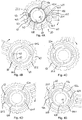
- FIG. 2 In the FIG. 2 are individual components of the stop mechanism 30 shown in detail, wherein a stop ring of the stop mechanism 30 only in the FIGS. 4A to 5C is shown. It is both a collar of the upper in FIG. 1B shown rotatable connection as well as a collar of the lower in FIG. 1B shown rotatable connection recognizable.
- the positive contours of the collars are slightly rotated to each other, in particular by an angle of about 5 °, so that both positive contours are recognizable.
- the stop mechanism 30 has the adjusting ring 60 and a rotary block 50 which are arranged concentrically with the stop ring around the spindle 10.
- the stop ring can be arranged in the cavity K formed between the rotary block 50 and the spindle 10.
- the rotary block 50 has two opposite stops 52a, 52b which project radially inwards on an inner surface 50.2 of the rotary block 50.
- the stops 52a, 52b each have two radial flanks 52.1 and a concave radially outwardly curved inner surface 52.2.
- the rotary block 50 has a stop 53 which protrudes radially outward on an outer surface 50.1 of the rotary block 50.
- the stop 53 has two flat opposite side surfaces (radial flanks) 53.1, which are set up to forward an angular momentum.
- the stop 53 has a convex radially outwardly curved outer surface 53.2, on which the adjusting ring 60 can slide along.
- the adjusting ring 60 has a counter-stop 63 projecting radially inward on an inner lateral surface 60.2, with a concavely curved inner surface 63.2, on which the rotary block 50 can slide with an outer lateral surface 50.1. Furthermore, the counter-abutment 63 has two flat opposite side surfaces (radial flanks) 63.1, which are set up to forward an angular momentum.
- the adjusting ring 60 and the rotary block 50 and the stop ring, not shown, are arranged concentrically with each other and concentric with the spindle 10.
- the anti-rotation device 23 has two webs 23.2 and an engagement element 23.1 fixable therebetween.
- a bushing 23.3 can be provided both on the webs and on the engagement element, as in FIG FIG. 3 shown.
- the engagement element 23.1 engages between two teeth 64.1 of the positive contour 64 radially in the adjusting ring 60 a.
- the teeth 64.1 are arranged on an outer circumferential surface 60.1 of the adjusting ring 60.
- the bushing 20 has a stop 22.2 protruding in the axial direction, against which the adjusting ring 60 bears radially on the outside.
- the stop 22.2 of the sleeve is integrally provided on a ring portion 22 of the sleeve 20, in particular cast, and forms together with the sleeve 20 a rotatable about the axis of rotation structure, as in FIG. 3 shown.
- a damping element 90 in the form of an elastic plate or mat is arranged in each case.
- the rotary block or intermediate ring 50 serves to increase the achievable angle of rotation.
- the end of the rotation range can be adjusted via the orientation of the spindle 10.
- the stop mechanism may e.g. be adjusted by the engagement member 23.1 of the rotation 23 is released and the adjusting ring 60 is rotated to the desired position, and then the engagement member 23.1 is brought back into engagement with the adjusting ring 60. If the stop 22.2 of the sleeve and the counter-stop 63 of the adjusting ring 60 are arranged directly next to one another, the largest angle of rotation can be realized. Inserted damping elements 90 can record the kinetic energy of a respective carrier upon reaching the stop.
- the bushing 20 is fork-shaped and has two ring sections 22, each having a passage 21 for the spindle 10, wherein at the upper ring portion 22, an annular edge 22a is formed with a convex radially outwardly curved outer surface 22.4.
- the stop 22.2 protrudes from an end face portion 22.1 of the annular edge 22a in the axial direction upward.
- the outer surface of the stop 22.2 is arranged on the same pitch circle as the curved outer surface 22.4.
- the curved outer surface 22.4 also forms the outer surface of the stop 22.2.
- the upper ring portion 22 also has an annular contact surface 22.5 for the adjusting ring 60, wherein the adjusting ring 60 can be mounted either on the end face portion 22.1 and / or on the contact surface 22.5.
- This embodiment of the sleeve 20 allows a structurally easily realizable arrangement of the stop mechanism 30 on the sleeve 20th
- the stop 22.2 also has a concave radially outwardly curved inner surface 22.3 and the two flat side surfaces (radial edges) 22.6.
- the rotary block 50 can slide along the inner surface 22.3.
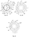
- FIGS. 4A to 4E an arrangement is shown, by means of which a rotation range can be set with a rotation angle greater than 360 °, in particular approximately 375 ° or 380 °.
- the FIGS. 4A to 4E show five different positions of the carrier 102 and the sleeve relative to the spindle 10, wherein the spindle 10 is arranged together with the stop ring 40 in a single stationary position.
- FIGS. 4A to 4E are each the three concentrically nested components 40, 50, 60 of the stop mechanism shown.
- the stop ring 40 has two radially inwardly arranged projections or springs 43 a, 43 b, which engage in the spindle 10 and ensure a rotationally secure arrangement of the stop ring 40 relative to the spindle 10.
- the springs are integrally formed on the stop ring 40.
- the springs 43a, 43b can also be replaced in each case by feather keys, which can be used on an inner circumferential surface in corresponding grooves of the stop ring 40.
- the fixed structure can be provided by the spindle 10 in connection with the stop ring 40, wherein the stop ring 40 is connected via a tongue and groove connection 13, 43 a, 43 b against rotation with the spindle 10.
- the stop ring 40 also has two stops 42a, 42b, which project in the radial direction on the outside on an outer circumferential surface 40.1 of the stop ring 40.
- the stops 42a, 42b each have radial edges 42.1, to which the rotary block 50 can strike. Furthermore, the stops 42a, 42b each convex radially outwardly curved outer surfaces 42.2 on which the rotary block 50 can slide along.
- the sleeve or carrier 102 is rotated about the spindle 10 in the clockwise direction as indicated by the arrow.
- FIG. 4b the carrier is shown rotated slightly more than 180 ° about the spindle 10. Together with the carrier, the stop 22.2 of the socket and the adjusting ring have been rotated.
- the intermediate ring 50 is still at the same position as in FIG. 4A arranged.
- FIG. 4C the stop 22.2 has been rotated to the stop 53 of the intermediate ring 50. From this rotational position of the intermediate ring 50 is taken or rotated by means of the stop 22.2.
- a rotational position is shown in which the intermediate ring has been rotated relative to the stop ring.
- FIG. 4E is shown an end position, corresponding to a rotation angle of about 375 °.
- the relatively large relative rotation angle at which in the FIGS. 4A to 4E embodiment shown can be adjusted by the stop 53 of the rotary block 50 is disposed in a ring cavity RK2 between the stop 22.2 of the sleeve and the counter-abutment 63 of the adjusting ring 60, which extends over a maximum possible arc of, for example, 310 ° to 330 ° ,
- the stop 22.2 of the sleeve and the counter-abutment 63 of the adjusting ring 60 are arranged directly next to one another, and the stop 53 of the rotary block 50 is arranged in the annular cavity RK2, wherein the annular cavity RK2 extends over a maximum large circular arc, in the illustrated embodiment in particular over about 295 °.
- the stop 53 of the rotary block 50 can thereby rotate over a circular arc of about 295 ° relative to the adjusting ring 60 and to the socket. Relative to the stop ring 40, the rotary block 50 can then rotate together with the adjusting ring 60 and the bushing by about 85 °, so that the result is a set angle of rotation of about 380 ° in the sum.
- the stop 22.2 and the counter-stop 63 may have the smallest possible circular arc extent, e.g. in the range of less than 10 °, preferably less than 7 ° or even less than 5 ° or 4 ° or 3 °, as long as the strengths of the materials used allow.
- the circular arc extent of the counterstops 52a, 52b of the rotary block 50 can be reduced, e.g. from about 90 ° to about 60 °.
- the circular arc extent of the annular cavity RK1 between the stop ring 40 and the rotary block 50 can be increased, which allows a larger relative angle of rotation.
- FIGS. 5A to 5C an arrangement is shown in which the carrier 102 and the sleeve together with the adjusting ring 60 is first rotated by about 40 ° relative to the rotary block 50, the stop ring 40 and the spindle 10 in a clockwise direction until the counter-abutment 63 on the stop 53 of the rotary block 50 comes to the plant, as in the FIG. 5B shown.
- the rotary block 50 initially remains static in the same position relative to the stop ring 40.
- the stop 53 of the rotary block 50 is located in the FIG. 5A at the stop 22.2 of the socket, and in the FIG.
- the stop 22.2 of the sleeve is further rotated by about 40 ° clockwise, and the stop 53 of the rotary block 50 comes to the counter-stop 63 of the adjusting ring 60 to the plant. From the in the FIG. 5B shown rotational position of the rotary block 50 is therefore rotated together with the adjusting ring in a clockwise direction.
- the stop 22.2 of the socket rotates to the same extent, ie, the distance between the rotary block 50 and the stop 22.2 remains unchanged, as in the FIG. 5C shown.
- the first Section RK2a extends over a circular arc of eg only 60 °.
- the stop 22.2 of the sleeve and the counter-stop 63 of the adjusting ring 60 are arranged relatively close to each other, and the stop 53 of the rotary block 50 is disposed therebetween.
- the stop 53 can thereby rotate over a circular arc of about 40 ° relative to the adjusting ring 60 and to the socket. Relative to the stop ring 40 of the rotary block 50 can then together with the Rotate collar 60 and the sleeve by about 85 °, namely by the counter-stops 52a, 52b are rotated in one / the annular cavity RK1 between the stop ring 40 and the rotary block 50, so that the sum results in a set rotation angle of about 125 °. In a second section RK2b of the annular cavity RK2 between the rotary block 50 and the adjusting ring 60 no stop is arranged. There is no relative rotation in this section of the annular cavity.
Priority Applications (1)
| Application Number | Priority Date | Filing Date | Title |
|---|---|---|---|
| EP15001221.9A EP2940367B1 (de) | 2014-04-24 | 2015-04-24 | Drehbare verbindung mit drehwinkelbegrenzung |
Applications Claiming Priority (2)
| Application Number | Priority Date | Filing Date | Title |
|---|---|---|---|
| EP14001482 | 2014-04-24 | ||
| EP15001221.9A EP2940367B1 (de) | 2014-04-24 | 2015-04-24 | Drehbare verbindung mit drehwinkelbegrenzung |
Publications (2)
| Publication Number | Publication Date |
|---|---|
| EP2940367A1 EP2940367A1 (de) | 2015-11-04 |
| EP2940367B1 true EP2940367B1 (de) | 2019-07-10 |
Family
ID=50630557
Family Applications (1)
| Application Number | Title | Priority Date | Filing Date |
|---|---|---|---|
| EP15001221.9A Active EP2940367B1 (de) | 2014-04-24 | 2015-04-24 | Drehbare verbindung mit drehwinkelbegrenzung |
Country Status (3)
| Country | Link |
|---|---|
| US (1) | US10247352B2 (zh) |
| EP (1) | EP2940367B1 (zh) |
| CN (1) | CN105003797B (zh) |
Families Citing this family (11)
| Publication number | Priority date | Publication date | Assignee | Title |
|---|---|---|---|---|
| EP2937618B1 (de) | 2014-04-24 | 2017-09-06 | Ondal Medical Systems GmbH | Drehbare Verbindung mit Drehwinkelbegrenzung |
| EP2937617B1 (de) | 2014-04-24 | 2017-03-01 | Ondal Medical Systems GmbH | Drehbare Verbindung mit Drehwinkelbegrenzung |
| EP2937619B1 (de) | 2014-04-24 | 2017-03-15 | Ondal Medical Systems GmbH | Drehbare Verbindung mit Drehwinkelbegrenzung |
| US10995872B1 (en) * | 2017-10-25 | 2021-05-04 | Lyndon J. Hurley | Pivoting support assembly |
| EP3604844A1 (de) | 2018-08-03 | 2020-02-05 | Ondal Medical Systems GmbH | Lageranordnung |
| US11819460B2 (en) * | 2019-11-22 | 2023-11-21 | Baxter Medical Systems Gmbh + Co. Kg | Collision prevention system for overhead assembly |
| CN111266039A (zh) * | 2020-03-06 | 2020-06-12 | 常熟迈得医疗器械技术服务有限公司 | 一种培养基溶解加热搅拌装置 |
| JP7356948B2 (ja) | 2020-04-10 | 2023-10-05 | スガツネ工業株式会社 | 回転支持装置 |
| EP3906884A1 (en) * | 2020-05-04 | 2021-11-10 | F.A.R.O. FABBRICA APPARECCHIATURE RAZIONALI ODONTOIATRICHE S.p.A. | Operating lamp |
| AU2021416514A1 (en) * | 2021-01-06 | 2023-08-03 | American Sterilizer Company | Medical device support system including rotational control mechanism |
| CN115419795B (zh) * | 2022-11-03 | 2023-02-03 | 新聚(徐州)安全科技有限公司 | 一种便于使用的工程地质测绘设备 |
Family Cites Families (32)
| Publication number | Priority date | Publication date | Assignee | Title |
|---|---|---|---|---|
| US1634922A (en) * | 1924-04-18 | 1927-07-05 | American Motor Body Corp | Revolving chair |
| FR1341061A (fr) | 1962-11-20 | 1963-10-25 | Quarzlampen Gmbh | Scialytique à bras articulés |
| US3713618A (en) * | 1971-03-22 | 1973-01-30 | Krueger Metal Products | Self centering support |
| DE3808327C2 (de) | 1987-03-21 | 1997-10-23 | Krause Robert Gmbh Co Kg | Schwenkarmvorrichtung |
| DE8903956U1 (zh) | 1989-03-31 | 1990-10-18 | Heraeus Instruments Gmbh, 6450 Hanau, De | |
| US5123768A (en) | 1991-08-06 | 1992-06-23 | Franklin Ronald D | Articulating positioning device for tools |
| DE4306802C1 (de) | 1993-03-04 | 1994-08-04 | Kreuzer Gmbh & Co Ohg | Deckenstativ |
| US6079949A (en) | 1998-11-13 | 2000-06-27 | Lasko Holdings, Inc. | Ratchet assembly for pedestal fan |
| AU2597501A (en) | 1999-12-23 | 2001-07-03 | Hill-Rom Services, Inc. | Surgical theater system |
| US7922671B2 (en) | 2002-01-30 | 2011-04-12 | Natus Medical Incorporated | Method and apparatus for automatic non-cooperative frequency specific assessment of hearing impairment and fitting of hearing aids |
| DE50305174D1 (de) | 2003-04-29 | 2006-11-09 | Trumpf Kreuzer Med Sys Gmbh | Feststellbremse und medizinisches Deckenstativ mit einer solchen Feststellbremse |
| WO2005021986A1 (en) | 2003-08-27 | 2005-03-10 | Ergotron, Inc. | Locking joint for support arm |
| US20060285915A1 (en) | 2005-06-01 | 2006-12-21 | Norgren Automotive, Inc. | Apparatus for incrementally adjusting a modular tooling coupling |
| US7452088B2 (en) | 2006-03-07 | 2008-11-18 | Velvac, Incorporated | Mirror with adjustable detent |
| US8056874B2 (en) | 2007-06-08 | 2011-11-15 | Blue Sky Designs, Inc. | Mounting and positioning apparatus for increased user independence |
| DE102008011129A1 (de) | 2008-02-26 | 2009-08-27 | Berchtold Holding Gmbh | Aufhängung |
| DE202009013767U1 (de) | 2009-10-09 | 2010-03-11 | Mekra Lang Gmbh & Co. Kg | Rastgelenk und Aussenspiegel mit einem solchen Rastgelenk |
| EP2325541B1 (en) * | 2009-11-18 | 2013-05-22 | Ondal Medical Systems GmbH | Adjustable stop mechanism for rotatable connection |
| US8591444B2 (en) | 2010-06-25 | 2013-11-26 | Djo, Llc | Hinge for an orthopedic brace |
| CN201779414U (zh) | 2010-07-14 | 2011-03-30 | 美商林特有限公司 | 支架柱头结构 |
| US9095946B2 (en) | 2011-02-08 | 2015-08-04 | Norgren Automation Solutions, Llc | Modular tooling apparatus having serrated teeth for orbital and linear adjustment |
| US9267537B2 (en) | 2012-04-06 | 2016-02-23 | Koninklijke Philips N.V. | Universal tiltable luminaire support |
| US9280037B2 (en) | 2012-05-03 | 2016-03-08 | Serview, Inc. | Machine vision camera mount with rotational adjustment |
| WO2014072964A1 (en) | 2012-11-12 | 2014-05-15 | Oasys Healthcare Corporation | Cabling for central axis pendant system |
| US20140314538A1 (en) * | 2013-04-18 | 2014-10-23 | Transenterix Surgical, Inc. | Support arm system for medical equipment |
| DE102013207783A1 (de) | 2013-04-29 | 2014-10-30 | Schaeffler Technologies Gmbh & Co. Kg | Drehverbindung |
| CN105377630B (zh) | 2013-06-26 | 2018-08-28 | 梅克拉-朗两合公司 | 用于转动连接第一和第二铰接臂的旋转接头系统及配备该旋转接头系统的反射镜支架和反射镜 |
| WO2015085243A1 (en) | 2013-12-05 | 2015-06-11 | Innovative Office Products, Llc | Expandable multi-display support apparatus |
| EP2937618B1 (de) | 2014-04-24 | 2017-09-06 | Ondal Medical Systems GmbH | Drehbare Verbindung mit Drehwinkelbegrenzung |
| EP2937617B1 (de) * | 2014-04-24 | 2017-03-01 | Ondal Medical Systems GmbH | Drehbare Verbindung mit Drehwinkelbegrenzung |
| EP2937619B1 (de) * | 2014-04-24 | 2017-03-15 | Ondal Medical Systems GmbH | Drehbare Verbindung mit Drehwinkelbegrenzung |
| DE102016003133B4 (de) | 2016-03-15 | 2017-09-28 | Eberhard-Karls-Universität Tübingen | Verfahren zur automatischen Bestimmung einer individuellen Funktion einer DPOAE-Pegelkarte eines menschlichen oder tierischen Gehörs |
-
2015
- 2015-04-24 US US14/695,332 patent/US10247352B2/en active Active
- 2015-04-24 CN CN201510202069.7A patent/CN105003797B/zh active Active
- 2015-04-24 EP EP15001221.9A patent/EP2940367B1/de active Active
Also Published As
| Publication number | Publication date |
|---|---|
| CN105003797A (zh) | 2015-10-28 |
| CN105003797B (zh) | 2019-05-31 |
| US20150308611A1 (en) | 2015-10-29 |
| EP2940367A1 (de) | 2015-11-04 |
| US10247352B2 (en) | 2019-04-02 |
Similar Documents
| Publication | Publication Date | Title |
|---|---|---|
| EP2940367B1 (de) | Drehbare verbindung mit drehwinkelbegrenzung | |
| EP2937619B1 (de) | Drehbare Verbindung mit Drehwinkelbegrenzung | |
| EP2937617B1 (de) | Drehbare Verbindung mit Drehwinkelbegrenzung | |
| EP2937618B1 (de) | Drehbare Verbindung mit Drehwinkelbegrenzung | |
| EP2241416B1 (de) | Roboter mit Delta-Kinematik | |
| EP2525947B1 (de) | Hexapod | |
| EP2359988B1 (de) | Verfahren zum Kalibrieren eines Parallelroboters | |
| EP3174488B1 (de) | Buchse, tragarm und tragsystem für eine medizintechnische stativvorrichtung | |
| EP3206653B1 (de) | Montagevorrichtung mit drehkupplung für eine stativvorrichtung | |
| WO2017153500A1 (de) | Roboterarm | |
| DE112017000578T5 (de) | Roboterarmmechanismus | |
| WO2011110448A1 (de) | Rastbeschlag | |
| EP3360633A1 (de) | Vorrichtung und spann-gehäuse | |
| DE10142434A1 (de) | Antriebs- und Verriegelungsaggregat | |
| WO2019174883A1 (de) | Armgelenk für einen manipulator und manipulator | |
| DE3113184C2 (zh) | ||
| EP3143970A1 (de) | Gelenkverbindung mit einer antriebseinrichtung sowie verfahren zur ansteuerung einer schwenkbewegung einer gelenkverbindung | |
| EP3030790B1 (de) | Getriebeverdichter und verfahren zur montage | |
| DE3504233A1 (de) | Greiferarm fuer handhabungsgeraete | |
| EP3206652A1 (de) | Montagevorrichtung für eine stativvorrichtung sowie montagesystem mit der montagevorrichtung | |
| EP3626406A1 (de) | Roboter mit komplementären befestigungselementen zur baugruppenverbindung | |
| EP3392419A1 (de) | Befestigungssystem | |
| DE102015013926A1 (de) | Covering rosette for a concealed sanitary fitting | |
| WO2016198416A1 (de) | Mikroskop mit reibschlüssigen antrieben | |
| DE202010015845U1 (de) | Vorrichtung für die Montage von Karosserieteilen an Fahrzeugkarosserien |
Legal Events
| Date | Code | Title | Description |
|---|---|---|---|
| PUAI | Public reference made under article 153(3) epc to a published international application that has entered the european phase |
Free format text: ORIGINAL CODE: 0009012 |
|
| AK | Designated contracting states |
Kind code of ref document: A1 Designated state(s): AL AT BE BG CH CY CZ DE DK EE ES FI FR GB GR HR HU IE IS IT LI LT LU LV MC MK MT NL NO PL PT RO RS SE SI SK SM TR |
|
| AX | Request for extension of the european patent |
Extension state: BA ME |
|
| 17P | Request for examination filed |
Effective date: 20160504 |
|
| RBV | Designated contracting states (corrected) |
Designated state(s): AL AT BE BG CH CY CZ DE DK EE ES FI FR GB GR HR HU IE IS IT LI LT LU LV MC MK MT NL NO PL PT RO RS SE SI SK SM TR |
|
| GRAP | Despatch of communication of intention to grant a patent |
Free format text: ORIGINAL CODE: EPIDOSNIGR1 |
|
| STAA | Information on the status of an ep patent application or granted ep patent |
Free format text: STATUS: GRANT OF PATENT IS INTENDED |
|
| INTG | Intention to grant announced |
Effective date: 20190201 |
|
| GRAS | Grant fee paid |
Free format text: ORIGINAL CODE: EPIDOSNIGR3 |
|
| GRAA | (expected) grant |
Free format text: ORIGINAL CODE: 0009210 |
|
| STAA | Information on the status of an ep patent application or granted ep patent |
Free format text: STATUS: THE PATENT HAS BEEN GRANTED |
|
| AK | Designated contracting states |
Kind code of ref document: B1 Designated state(s): AL AT BE BG CH CY CZ DE DK EE ES FI FR GB GR HR HU IE IS IT LI LT LU LV MC MK MT NL NO PL PT RO RS SE SI SK SM TR |
|
| REG | Reference to a national code |
Ref country code: GB Ref legal event code: FG4D Free format text: NOT ENGLISH |
|
| REG | Reference to a national code |
Ref country code: CH Ref legal event code: EP Ref country code: AT Ref legal event code: REF Ref document number: 1153954 Country of ref document: AT Kind code of ref document: T Effective date: 20190715 |
|
| REG | Reference to a national code |
Ref country code: DE Ref legal event code: R096 Ref document number: 502015009560 Country of ref document: DE |
|
| REG | Reference to a national code |
Ref country code: IE Ref legal event code: FG4D Free format text: LANGUAGE OF EP DOCUMENT: GERMAN |
|
| REG | Reference to a national code |
Ref country code: NL Ref legal event code: FP |
|
| REG | Reference to a national code |
Ref country code: LT Ref legal event code: MG4D |
|
| PG25 | Lapsed in a contracting state [announced via postgrant information from national office to epo] |
Ref country code: LT Free format text: LAPSE BECAUSE OF FAILURE TO SUBMIT A TRANSLATION OF THE DESCRIPTION OR TO PAY THE FEE WITHIN THE PRESCRIBED TIME-LIMIT Effective date: 20190710 Ref country code: HR Free format text: LAPSE BECAUSE OF FAILURE TO SUBMIT A TRANSLATION OF THE DESCRIPTION OR TO PAY THE FEE WITHIN THE PRESCRIBED TIME-LIMIT Effective date: 20190710 Ref country code: BG Free format text: LAPSE BECAUSE OF FAILURE TO SUBMIT A TRANSLATION OF THE DESCRIPTION OR TO PAY THE FEE WITHIN THE PRESCRIBED TIME-LIMIT Effective date: 20191010 Ref country code: PT Free format text: LAPSE BECAUSE OF FAILURE TO SUBMIT A TRANSLATION OF THE DESCRIPTION OR TO PAY THE FEE WITHIN THE PRESCRIBED TIME-LIMIT Effective date: 20191111 Ref country code: SE Free format text: LAPSE BECAUSE OF FAILURE TO SUBMIT A TRANSLATION OF THE DESCRIPTION OR TO PAY THE FEE WITHIN THE PRESCRIBED TIME-LIMIT Effective date: 20190710 Ref country code: FI Free format text: LAPSE BECAUSE OF FAILURE TO SUBMIT A TRANSLATION OF THE DESCRIPTION OR TO PAY THE FEE WITHIN THE PRESCRIBED TIME-LIMIT Effective date: 20190710 Ref country code: NO Free format text: LAPSE BECAUSE OF FAILURE TO SUBMIT A TRANSLATION OF THE DESCRIPTION OR TO PAY THE FEE WITHIN THE PRESCRIBED TIME-LIMIT Effective date: 20191010 |
|
| PG25 | Lapsed in a contracting state [announced via postgrant information from national office to epo] |
Ref country code: ES Free format text: LAPSE BECAUSE OF FAILURE TO SUBMIT A TRANSLATION OF THE DESCRIPTION OR TO PAY THE FEE WITHIN THE PRESCRIBED TIME-LIMIT Effective date: 20190710 Ref country code: LV Free format text: LAPSE BECAUSE OF FAILURE TO SUBMIT A TRANSLATION OF THE DESCRIPTION OR TO PAY THE FEE WITHIN THE PRESCRIBED TIME-LIMIT Effective date: 20190710 Ref country code: GR Free format text: LAPSE BECAUSE OF FAILURE TO SUBMIT A TRANSLATION OF THE DESCRIPTION OR TO PAY THE FEE WITHIN THE PRESCRIBED TIME-LIMIT Effective date: 20191011 Ref country code: IS Free format text: LAPSE BECAUSE OF FAILURE TO SUBMIT A TRANSLATION OF THE DESCRIPTION OR TO PAY THE FEE WITHIN THE PRESCRIBED TIME-LIMIT Effective date: 20191110 Ref country code: RS Free format text: LAPSE BECAUSE OF FAILURE TO SUBMIT A TRANSLATION OF THE DESCRIPTION OR TO PAY THE FEE WITHIN THE PRESCRIBED TIME-LIMIT Effective date: 20190710 Ref country code: AL Free format text: LAPSE BECAUSE OF FAILURE TO SUBMIT A TRANSLATION OF THE DESCRIPTION OR TO PAY THE FEE WITHIN THE PRESCRIBED TIME-LIMIT Effective date: 20190710 |
|
| PG25 | Lapsed in a contracting state [announced via postgrant information from national office to epo] |
Ref country code: EE Free format text: LAPSE BECAUSE OF FAILURE TO SUBMIT A TRANSLATION OF THE DESCRIPTION OR TO PAY THE FEE WITHIN THE PRESCRIBED TIME-LIMIT Effective date: 20190710 Ref country code: RO Free format text: LAPSE BECAUSE OF FAILURE TO SUBMIT A TRANSLATION OF THE DESCRIPTION OR TO PAY THE FEE WITHIN THE PRESCRIBED TIME-LIMIT Effective date: 20190710 Ref country code: DK Free format text: LAPSE BECAUSE OF FAILURE TO SUBMIT A TRANSLATION OF THE DESCRIPTION OR TO PAY THE FEE WITHIN THE PRESCRIBED TIME-LIMIT Effective date: 20190710 Ref country code: PL Free format text: LAPSE BECAUSE OF FAILURE TO SUBMIT A TRANSLATION OF THE DESCRIPTION OR TO PAY THE FEE WITHIN THE PRESCRIBED TIME-LIMIT Effective date: 20190710 |
|
| PG25 | Lapsed in a contracting state [announced via postgrant information from national office to epo] |
Ref country code: SK Free format text: LAPSE BECAUSE OF FAILURE TO SUBMIT A TRANSLATION OF THE DESCRIPTION OR TO PAY THE FEE WITHIN THE PRESCRIBED TIME-LIMIT Effective date: 20190710 Ref country code: IS Free format text: LAPSE BECAUSE OF FAILURE TO SUBMIT A TRANSLATION OF THE DESCRIPTION OR TO PAY THE FEE WITHIN THE PRESCRIBED TIME-LIMIT Effective date: 20200224 Ref country code: SM Free format text: LAPSE BECAUSE OF FAILURE TO SUBMIT A TRANSLATION OF THE DESCRIPTION OR TO PAY THE FEE WITHIN THE PRESCRIBED TIME-LIMIT Effective date: 20190710 |
|
| REG | Reference to a national code |
Ref country code: DE Ref legal event code: R097 Ref document number: 502015009560 Country of ref document: DE |
|
| PLBE | No opposition filed within time limit |
Free format text: ORIGINAL CODE: 0009261 |
|
| STAA | Information on the status of an ep patent application or granted ep patent |
Free format text: STATUS: NO OPPOSITION FILED WITHIN TIME LIMIT |
|
| PG2D | Information on lapse in contracting state deleted |
Ref country code: IS |
|
| 26N | No opposition filed |
Effective date: 20200603 |
|
| PG25 | Lapsed in a contracting state [announced via postgrant information from national office to epo] |
Ref country code: SI Free format text: LAPSE BECAUSE OF FAILURE TO SUBMIT A TRANSLATION OF THE DESCRIPTION OR TO PAY THE FEE WITHIN THE PRESCRIBED TIME-LIMIT Effective date: 20190710 |
|
| PG25 | Lapsed in a contracting state [announced via postgrant information from national office to epo] |
Ref country code: MC Free format text: LAPSE BECAUSE OF FAILURE TO SUBMIT A TRANSLATION OF THE DESCRIPTION OR TO PAY THE FEE WITHIN THE PRESCRIBED TIME-LIMIT Effective date: 20190710 |
|
| REG | Reference to a national code |
Ref country code: CH Ref legal event code: PL |
|
| PG25 | Lapsed in a contracting state [announced via postgrant information from national office to epo] |
Ref country code: CH Free format text: LAPSE BECAUSE OF NON-PAYMENT OF DUE FEES Effective date: 20200430 Ref country code: LI Free format text: LAPSE BECAUSE OF NON-PAYMENT OF DUE FEES Effective date: 20200430 Ref country code: LU Free format text: LAPSE BECAUSE OF NON-PAYMENT OF DUE FEES Effective date: 20200424 |
|
| REG | Reference to a national code |
Ref country code: BE Ref legal event code: MM Effective date: 20200430 |
|
| PG25 | Lapsed in a contracting state [announced via postgrant information from national office to epo] |
Ref country code: BE Free format text: LAPSE BECAUSE OF NON-PAYMENT OF DUE FEES Effective date: 20200430 |
|
| GBPC | Gb: european patent ceased through non-payment of renewal fee |
Effective date: 20200424 |
|
| PG25 | Lapsed in a contracting state [announced via postgrant information from national office to epo] |
Ref country code: GB Free format text: LAPSE BECAUSE OF NON-PAYMENT OF DUE FEES Effective date: 20200424 Ref country code: IE Free format text: LAPSE BECAUSE OF NON-PAYMENT OF DUE FEES Effective date: 20200424 |
|
| REG | Reference to a national code |
Ref country code: AT Ref legal event code: MM01 Ref document number: 1153954 Country of ref document: AT Kind code of ref document: T Effective date: 20200424 |
|
| PG25 | Lapsed in a contracting state [announced via postgrant information from national office to epo] |
Ref country code: AT Free format text: LAPSE BECAUSE OF NON-PAYMENT OF DUE FEES Effective date: 20200424 |
|
| PG25 | Lapsed in a contracting state [announced via postgrant information from national office to epo] |
Ref country code: MT Free format text: LAPSE BECAUSE OF FAILURE TO SUBMIT A TRANSLATION OF THE DESCRIPTION OR TO PAY THE FEE WITHIN THE PRESCRIBED TIME-LIMIT Effective date: 20190710 Ref country code: CY Free format text: LAPSE BECAUSE OF FAILURE TO SUBMIT A TRANSLATION OF THE DESCRIPTION OR TO PAY THE FEE WITHIN THE PRESCRIBED TIME-LIMIT Effective date: 20190710 |
|
| PG25 | Lapsed in a contracting state [announced via postgrant information from national office to epo] |
Ref country code: MK Free format text: LAPSE BECAUSE OF FAILURE TO SUBMIT A TRANSLATION OF THE DESCRIPTION OR TO PAY THE FEE WITHIN THE PRESCRIBED TIME-LIMIT Effective date: 20190710 |
|
| PGFP | Annual fee paid to national office [announced via postgrant information from national office to epo] |
Ref country code: NL Payment date: 20230417 Year of fee payment: 9 |
|
| P01 | Opt-out of the competence of the unified patent court (upc) registered |
Effective date: 20230526 |
|
| PGFP | Annual fee paid to national office [announced via postgrant information from national office to epo] |
Ref country code: IT Payment date: 20230428 Year of fee payment: 9 Ref country code: FR Payment date: 20230417 Year of fee payment: 9 Ref country code: DE Payment date: 20230307 Year of fee payment: 9 Ref country code: CZ Payment date: 20230417 Year of fee payment: 9 |
|
| PGFP | Annual fee paid to national office [announced via postgrant information from national office to epo] |
Ref country code: TR Payment date: 20230424 Year of fee payment: 9 |