EP2938886B1 - Valve de distribution dotée d'une configuration avec deux solenoids - Google Patents
Valve de distribution dotée d'une configuration avec deux solenoids Download PDFInfo
- Publication number
- EP2938886B1 EP2938886B1 EP13824725.9A EP13824725A EP2938886B1 EP 2938886 B1 EP2938886 B1 EP 2938886B1 EP 13824725 A EP13824725 A EP 13824725A EP 2938886 B1 EP2938886 B1 EP 2938886B1
- Authority
- EP
- European Patent Office
- Prior art keywords
- solenoid
- valve
- spool
- energizing
- pilot
- Prior art date
- Legal status (The legal status is an assumption and is not a legal conclusion. Google has not performed a legal analysis and makes no representation as to the accuracy of the status listed.)
- Not-in-force
Links
Images


Classifications
-
- F—MECHANICAL ENGINEERING; LIGHTING; HEATING; WEAPONS; BLASTING
- F15—FLUID-PRESSURE ACTUATORS; HYDRAULICS OR PNEUMATICS IN GENERAL
- F15B—SYSTEMS ACTING BY MEANS OF FLUIDS IN GENERAL; FLUID-PRESSURE ACTUATORS, e.g. SERVOMOTORS; DETAILS OF FLUID-PRESSURE SYSTEMS, NOT OTHERWISE PROVIDED FOR
- F15B13/00—Details of servomotor systems ; Valves for servomotor systems
- F15B13/02—Fluid distribution or supply devices characterised by their adaptation to the control of servomotors
- F15B13/04—Fluid distribution or supply devices characterised by their adaptation to the control of servomotors for use with a single servomotor
- F15B13/042—Fluid distribution or supply devices characterised by their adaptation to the control of servomotors for use with a single servomotor operated by fluid pressure
- F15B13/043—Fluid distribution or supply devices characterised by their adaptation to the control of servomotors for use with a single servomotor operated by fluid pressure with electrically-controlled pilot valves
- F15B13/0431—Fluid distribution or supply devices characterised by their adaptation to the control of servomotors for use with a single servomotor operated by fluid pressure with electrically-controlled pilot valves the electrical control resulting in an on-off function
-
- F—MECHANICAL ENGINEERING; LIGHTING; HEATING; WEAPONS; BLASTING
- F15—FLUID-PRESSURE ACTUATORS; HYDRAULICS OR PNEUMATICS IN GENERAL
- F15B—SYSTEMS ACTING BY MEANS OF FLUIDS IN GENERAL; FLUID-PRESSURE ACTUATORS, e.g. SERVOMOTORS; DETAILS OF FLUID-PRESSURE SYSTEMS, NOT OTHERWISE PROVIDED FOR
- F15B13/00—Details of servomotor systems ; Valves for servomotor systems
- F15B13/02—Fluid distribution or supply devices characterised by their adaptation to the control of servomotors
- F15B13/04—Fluid distribution or supply devices characterised by their adaptation to the control of servomotors for use with a single servomotor
- F15B13/044—Fluid distribution or supply devices characterised by their adaptation to the control of servomotors for use with a single servomotor operated by electrically-controlled means, e.g. solenoids, torque-motors
-
- F—MECHANICAL ENGINEERING; LIGHTING; HEATING; WEAPONS; BLASTING
- F15—FLUID-PRESSURE ACTUATORS; HYDRAULICS OR PNEUMATICS IN GENERAL
- F15B—SYSTEMS ACTING BY MEANS OF FLUIDS IN GENERAL; FLUID-PRESSURE ACTUATORS, e.g. SERVOMOTORS; DETAILS OF FLUID-PRESSURE SYSTEMS, NOT OTHERWISE PROVIDED FOR
- F15B21/00—Common features of fluid actuator systems; Fluid-pressure actuator systems or details thereof, not covered by any other group of this subclass
- F15B21/003—Systems with different interchangeable components, e.g. using preassembled kits
-
- F—MECHANICAL ENGINEERING; LIGHTING; HEATING; WEAPONS; BLASTING
- F16—ENGINEERING ELEMENTS AND UNITS; GENERAL MEASURES FOR PRODUCING AND MAINTAINING EFFECTIVE FUNCTIONING OF MACHINES OR INSTALLATIONS; THERMAL INSULATION IN GENERAL
- F16K—VALVES; TAPS; COCKS; ACTUATING-FLOATS; DEVICES FOR VENTING OR AERATING
- F16K11/00—Multiple-way valves, e.g. mixing valves; Pipe fittings incorporating such valves
- F16K11/02—Multiple-way valves, e.g. mixing valves; Pipe fittings incorporating such valves with all movable sealing faces moving as one unit
- F16K11/06—Multiple-way valves, e.g. mixing valves; Pipe fittings incorporating such valves with all movable sealing faces moving as one unit comprising only sliding valves, i.e. sliding closure elements
- F16K11/065—Multiple-way valves, e.g. mixing valves; Pipe fittings incorporating such valves with all movable sealing faces moving as one unit comprising only sliding valves, i.e. sliding closure elements with linearly sliding closure members
- F16K11/07—Multiple-way valves, e.g. mixing valves; Pipe fittings incorporating such valves with all movable sealing faces moving as one unit comprising only sliding valves, i.e. sliding closure elements with linearly sliding closure members with cylindrical slides
- F16K11/0704—Multiple-way valves, e.g. mixing valves; Pipe fittings incorporating such valves with all movable sealing faces moving as one unit comprising only sliding valves, i.e. sliding closure elements with linearly sliding closure members with cylindrical slides comprising locking elements
-
- F—MECHANICAL ENGINEERING; LIGHTING; HEATING; WEAPONS; BLASTING
- F16—ENGINEERING ELEMENTS AND UNITS; GENERAL MEASURES FOR PRODUCING AND MAINTAINING EFFECTIVE FUNCTIONING OF MACHINES OR INSTALLATIONS; THERMAL INSULATION IN GENERAL
- F16K—VALVES; TAPS; COCKS; ACTUATING-FLOATS; DEVICES FOR VENTING OR AERATING
- F16K31/00—Actuating devices; Operating means; Releasing devices
- F16K31/02—Actuating devices; Operating means; Releasing devices electric; magnetic
- F16K31/06—Actuating devices; Operating means; Releasing devices electric; magnetic using a magnet, e.g. diaphragm valves, cutting off by means of a liquid
- F16K31/0603—Multiple-way valves
- F16K31/061—Sliding valves
- F16K31/0613—Sliding valves with cylindrical slides
-
- F—MECHANICAL ENGINEERING; LIGHTING; HEATING; WEAPONS; BLASTING
- F16—ENGINEERING ELEMENTS AND UNITS; GENERAL MEASURES FOR PRODUCING AND MAINTAINING EFFECTIVE FUNCTIONING OF MACHINES OR INSTALLATIONS; THERMAL INSULATION IN GENERAL
- F16K—VALVES; TAPS; COCKS; ACTUATING-FLOATS; DEVICES FOR VENTING OR AERATING
- F16K31/00—Actuating devices; Operating means; Releasing devices
- F16K31/02—Actuating devices; Operating means; Releasing devices electric; magnetic
- F16K31/06—Actuating devices; Operating means; Releasing devices electric; magnetic using a magnet, e.g. diaphragm valves, cutting off by means of a liquid
- F16K31/0675—Electromagnet aspects, e.g. electric supply therefor
- F16K31/0679—Electromagnet aspects, e.g. electric supply therefor with more than one energising coil
-
- F—MECHANICAL ENGINEERING; LIGHTING; HEATING; WEAPONS; BLASTING
- F15—FLUID-PRESSURE ACTUATORS; HYDRAULICS OR PNEUMATICS IN GENERAL
- F15B—SYSTEMS ACTING BY MEANS OF FLUIDS IN GENERAL; FLUID-PRESSURE ACTUATORS, e.g. SERVOMOTORS; DETAILS OF FLUID-PRESSURE SYSTEMS, NOT OTHERWISE PROVIDED FOR
- F15B13/00—Details of servomotor systems ; Valves for servomotor systems
- F15B13/02—Fluid distribution or supply devices characterised by their adaptation to the control of servomotors
- F15B13/04—Fluid distribution or supply devices characterised by their adaptation to the control of servomotors for use with a single servomotor
- F15B13/0401—Valve members; Fluid interconnections therefor
- F15B13/0402—Valve members; Fluid interconnections therefor for linearly sliding valves, e.g. spool valves
-
- F—MECHANICAL ENGINEERING; LIGHTING; HEATING; WEAPONS; BLASTING
- F15—FLUID-PRESSURE ACTUATORS; HYDRAULICS OR PNEUMATICS IN GENERAL
- F15B—SYSTEMS ACTING BY MEANS OF FLUIDS IN GENERAL; FLUID-PRESSURE ACTUATORS, e.g. SERVOMOTORS; DETAILS OF FLUID-PRESSURE SYSTEMS, NOT OTHERWISE PROVIDED FOR
- F15B13/00—Details of servomotor systems ; Valves for servomotor systems
- F15B13/02—Fluid distribution or supply devices characterised by their adaptation to the control of servomotors
- F15B13/04—Fluid distribution or supply devices characterised by their adaptation to the control of servomotors for use with a single servomotor
- F15B13/0401—Valve members; Fluid interconnections therefor
- F15B2013/0412—Valve members; Fluid interconnections therefor with three positions
-
- Y—GENERAL TAGGING OF NEW TECHNOLOGICAL DEVELOPMENTS; GENERAL TAGGING OF CROSS-SECTIONAL TECHNOLOGIES SPANNING OVER SEVERAL SECTIONS OF THE IPC; TECHNICAL SUBJECTS COVERED BY FORMER USPC CROSS-REFERENCE ART COLLECTIONS [XRACs] AND DIGESTS
- Y10—TECHNICAL SUBJECTS COVERED BY FORMER USPC
- Y10T—TECHNICAL SUBJECTS COVERED BY FORMER US CLASSIFICATION
- Y10T137/00—Fluid handling
- Y10T137/8593—Systems
- Y10T137/86493—Multi-way valve unit
- Y10T137/86879—Reciprocating valve unit
Definitions
- the present invention relates generally to double-solenoid directional control valves.
- the present disclosure relates more specifically to methods for actuating a double-solenoid three-position directional control valve using the electrical input intended for a single-solenoid two-position directional control valve.
- a typical directional-control valve is comprised of a valve spool that slides linearly within a valve body.
- the valve spool is comprised of a discrete number of lobes, typically three, while the valve body is comprised of a discrete number of internal and external ports, typically five.
- various ports in the valve body are covered or exposed by the lobes of the valve spool, which in effect provides various configurations of connectivity between the ports in the valve body.
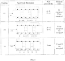
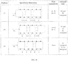
- FIG. 1 depicts a standard valve spool and body geometry. Specifically, as depicted in FIG.
- the valve spool of a typical directional-control valve incorporates three lobes, while the valve body of a typical directional-control valve incorporates five ports, which correspond to four distinct fluid ports, which are the supply (S), exhaust (E), and first and second actuator ports (A and B, respectively).
- the inlet port (S) is in fluid communication with the second actuator port (B)
- the exhaust port (E) is in fluid communication with the first actuator port (A).
- the valve spool slides to the second position (P2) the inlet port (S) is in fluid communication with the first actuator port (A), and the exhaust port (E) is in fluid communication with the second actuator port (B).
- the valve spool is commonly (though not universally) moved within the valve body between the first and second spool positions by a single solenoid actuator.
- the solenoid actuation can either be configured to be a direct-acting type, in which a solenoid actuator exerts a motive force directly on the valve spool, or of the pilot-actuated type, in which the solenoid actuator controls a pilot valve, which in turn controls the flow of a pressurized fluid, which in turn exerts motive force on the valve spool. The latter is in effect a mechanism of force amplification.
- valve In the case of a two-position valve, the valve is often actuated by a single solenoid actuator.
- solenoid actuator In the direct-acting type, energizing the solenoid actuator pushes the spool directly into the first position, while de-energizing the solenoid allows a return spring (or a similar return mechanism) to push the spool back to the second spool position.
- energizing the solenoid typically opens a pilot valve, which in turn enables a supply of pressurized fluid to fill a small cylinder adjacent to the spool and push the spool into the first position.
- De-energizing the solenoid de-pressurizes the pilot cylinder and allows a return spring (or a similar return mechanism) to push the spool back to the second spool position.
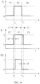
- the solenoid states associated with the two positions of a typical directional control valve are shown in FIG. 1 .
- the solenoid command corresponding to these states is illustrated in FIG. 2 , where a solenoid command (S) of one corresponds to energizing the single solenoid, and a command of zero corresponds to de-energizing the solenoid.
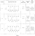
- the valve includes a third position of the spool within the valve body, which is physically located in an intermediate position approximately halfway between the first and second positions of the spool relative to the valve body.
- the third position is characterized by a different type of fluid connectivity relative to the first and second positions.
- all inlet and actuator ports might be isolated (i.e., none of the four ports are in fluid communication with each other), or both actuator ports might be connected to an exhaust port.
- Valves that provide the two fundamental positions, in addition to a third intermediate position, are called three-position directional-control valves.
- the valve is actuated by a pair of opposing solenoid actuators, such that energizing one solenoid while de-energizing the other moves the spool into the first position; reversing this pattern moves the spool into the second position; and de-energizing both solenoids allows a pair of centering springs to move the spool to the third, intermediate position.
- a pilot-operated valve operates similarly.
- the solenoid states associated with these three positions are shown in FIG. 3 . Note that the first and second spool positions provide the same port connectivity as the respective first and second spool positions in the two-position valve, while the third position provides a third type of port connectivity (which can have various purposes, depending on the application).
- the solenoid commands corresponding to the three spool positions of the double-solenoid valve are illustrated in FIG. 4 , where the two solenoid commands, S1 and S2, correspond to the first and second solenoid, respectively.
- a command value of one corresponds to energizing the respective solenoid, while a command value of zero corresponds to de-energizing the respective solenoid.
- GB 784 097 discloses a double-solenoid directional control valve in accordance with the preamble of claim 1.
- Exemplary embodiments of the present disclosure comprise a double-solenoid, three-position directional control valve that can operate from the electrical command intended to operate a single-solenoid, two-position valve, for specialized applications in which the third spool position is desired momentarily, when the spool is moved between the first and second spool positions.
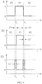
- the solenoid commands corresponding to a cyclic movement from the second spool position (P2) to the first spool position (P1), and back to the second position (P2) for the respective valves are shown in FIG. 5A .
- the bottom two plots in the figure show the normalized solenoid voltages (S1 and S2) for the first and second solenoids, respectively, required to provide the same movement between P1 and P2, with the additional energy-saving functionality.
- the shaded portion of the bottom figure (S2) indicates a fundamental problem with the use of the standard three-position configuration for purposes of obtaining equivalent functionality with the double-solenoid valve using the single-solenoid valve command.
- the second solenoid In order to maintain the double-solenoid three-position valve spool in the second position (P2), the second solenoid must be energized (as per FIGS.
- the electrical solenoid command to the single-solenoid valve is zero (i.e., the single solenoid of the valve is normally de-energized to maintain the second spool position), and thus no electrical power is present from the single-solenoid command to energize S2 in the three-position valve.
- a fundamental discrepancy exists between the electrical power requirements to maintain the second spool position in a single-solenoid and double-solenoid type directional control valves.
- Exemplary embodiments of the present disclosure comprise alternate configurations of a three-position double-solenoid directional control valve that circumvents this issue (requiring sustained electrical energy when none is present), and thus enables a double-solenoid three-position valve to function with the electrical command corresponding to a typical single-solenoid two-position valve.
- the present invention refers to a double-solenoid directional control valve comprising: a valve body; a first solenoid actuator; a second solenoid actuator; and a valve spool within the valve body, wherein the valve spool is configured to move within the valve body between a first position, a second position and a third position, where the third spool position lies between the first and second spool positions, and where the spool is maintained in the first and third positions by energizing at least the first or the second solenoid actuator, and where the spool is maintained in the second position by de-energizing both the first and the second solenoid actuators and where
- the first and second solenoid actuators are configured as pilot-operated type solenoid actuators, characterized in that one of the first or second solenoid controls a normally-closed pilot valve and the other solenoid controls a normally-open pilot valve.
- Particular embodiments further comprise a set of centering springs configured to maintain the spool in the third position in the absence of pressurization from the normally-closed pilot valve or the normally-open pilot valve.
- energizing both the first and second solenoids pressurizes the first pilot and maintains the valve spool in the first position.
- de-energizing both the first and second solenoids pressurizes the second pilot and maintains the valve spool in the second position.
- de-energizing the first solenoid and energizing the second solenoid de-pressurizes both pilots, and allows the centering springs to maintain the valve spool in the third position.
- the valve is operated by a single electrical input, which is high (energized) when the spool is commanded to the first position, and low (de-energized) when the spool is commanded to the second position.
- a high electrical input energizes both the first and second solenoids and maintains the spool in the first position.
- electrical energy from the single electrical input is stored in the valve when the spool is in the first position.
- At least one of a capacitor, a supercapacitor, or a battery is used to store electrical energy.
- stored electrical energy supplies power to temporarily energize at least one of the solenoid actuators.
- the stored electrical energy is used to energize the second solenoid actuator for a prescribed interval of time, which maintains the spool in the third position.
- only the second solenoid is initially energized for a prescribed period of time, which maintains the spool in the third position.
- the first solenoid is energized only after the second solenoid has been energized for a prescribed interval of time.
- the solenoid actuation is of the direct-acting type.
- at least one spring maintains the spool in the second position.
- energizing at least one solenoid maintains the spool in the first position.
- energizing at least one solenoid maintains the spool in the third position.
- the valve is operated by a single electrical input, which is either high (energized) or low (de-energized).
- electrical energy from the single electrical input is stored when the input is high.
- at least one of a capacitor, supercapacitor, or battery is used to store electrical energy.
- the stored electrical energy supplies power to energize at least one solenoid for a prescribed interval of time.
- only one solenoid is initially energized for a prescribed interval of time.
- the de-energized solenoid is energized after the energized solenoid has been energized for a prescribed interval of time.
- the lack of electrical power required to operate the three-position energy-saving valve can be circumvented by employing alternate actuation configurations for the three-position valve.
- de-energizing both solenoids allows a set of centering biasing members (e . g ., springs) to maintain the spool into the third (centered) spool position.
- This application proposes alternate actuation configurations for a three-position double-solenoid valve in which de-energizing both solenoids instead maintains the spool in the second (non-centered) spool position.
- the pilot-operated embodiment described here employs one solenoid that controls a normally-closed pilot, and one solenoid that controls a normally-open pilot.
- the three-position valve described here can be configured such that the first solenoid (S1) controls a normally-closed pilot valve, while the second solenoid (S2) controls a normal-open pilot valve.
- An electrical schematic of a circuit 100 that may be used in exemplary embodiments to control a single-solenoid two position valve is shown in FIG. 5B .
- the labels S, S1, and S2 correspond to the same (voltage levels) shown in FIGS. 5 , 7 , 9 and 11 .
- circuit 100 comprises a switching logic block 105.
- FIGS. 5-11 describe different strategies for the switching logic block 105.
- circuit 100 also comprises a first solenoid actuator 110, a second solenoid actuator 120, a capacitor 130.
- capacitor 130 may be configured as a capacitor, supercapacitor or battery.
- circuit 100 further comprises a regulator 140 and a voltage divider 150.
- regulator 140 and voltage divider 150 can be used to provide different voltage levels to different components in the circuit.
- the solenoid command voltage is 24 volts
- the logic circuitry voltage is 5 volts or 3.3 volts.
- the circuit logic can be implemented in a microcontroller, including for example, a small 8-bit microcontroller to implement the switching logic.
- FIG. 6 and FIG. 7 In contrast with the continuous unmet energy requirement to maintain P2 (indicated in FIG. 5A ), the configuration of FIG. 6 and FIG. 7 requires only a small, finite amount of actuation energy over a short period of time that is not directly supplied by the electrical source, corresponding to the period of dwell when the spool transits from the first to the second spool positions. Specifically, the shaded portion of FIG. 7 indicates the region of operation in which the solenoid S2 must be energized in the absence of direct electrical power from the standard single-solenoid electrical command.
- the dwell time ( ⁇ T) is short (on the order of tens to hundreds of milliseconds)
- the total energy required per cycle in this configuration is small, and can be provided by an energy storage methodology, such as a standard electrical capacitor, supercapacitor, or small rechargeable battery.
- this alternate configuration double-solenoid valve enables a method of operating the special case of a three-position valve described here (i.e., that dwells for a short period of time in the third position when moving between the first and second spool positions) that maintains electrical compatibility with a two-position single-solenoid valve command.
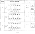
- FIG. 8 One such configuration of solenoid actuation for the three-position valve is illustrated in FIG. 8 .
- the first position is maintained by energizing only the S1 solenoid against a return spring;
- the second position is maintained by de-energizing both the S1 and S2 solenoids, allowing the return mechanism (e.g., springs) to maintain the spool in the second position;
- the third position is maintained by energizing only the S2 solenoid against the return spring.
- the solenoid commands required in this configuration, relative to a two-position standard command are shown in FIG. 9 , where the shaded portion of this figure indicates the region of operation in which the solenoid S2 must be energized in the absence of direct electrical power from the standard single-solenoid valve command.
- the first position is maintained by energizing both the S1 and S2 solenoids against a return spring; the second position is maintained by de-energizing both the S1 and S2 solenoids, allowing the return spring (or springs) to maintain the spool position; and the third position is maintained by energizing only the S1 solenoid against the return spring (or springs) to maintain the third position.
- the solenoid commands required in this configuration, relative to a two-position standard command, are shown in FIG. 11 .
- the shaded portion of the figure indicates the region of operation in which the solenoid S1 must be energized in the absence of direct electrical power from the standard single-solenoid valve command.
Landscapes
- Engineering & Computer Science (AREA)
- General Engineering & Computer Science (AREA)
- Mechanical Engineering (AREA)
- Physics & Mathematics (AREA)
- Fluid Mechanics (AREA)
- Electromagnetism (AREA)
- Chemical & Material Sciences (AREA)
- Analytical Chemistry (AREA)
- Magnetically Actuated Valves (AREA)
- Electromagnets (AREA)
Claims (11)
- Valve de distribution à deux solénoïdes comprenant :un corps de valve ;un premier actionneur à solénoïde (110) ;un second actionneur à solénoïde (120) ; etun tiroir de valve à l'intérieur du corps de valve, dans laquelle :le tiroir de valve est configuré pour se déplacer à l'intérieur du corps de valve entre une première position, une deuxième position et une troisième position, où la troisième position de tiroir se situe entre les première et deuxième positions de tiroir, et où le tiroir est maintenu dans les première et troisième positions par alimentation au moins du premier ou du second actionneur à solénoïde, et où le tiroir est maintenu dans la deuxième position par dés-alimentation tant du premier que du second actionneurs à solénoïde,caractérisé en ce que les premier et second actionneurs à solénoïde sont configurés en tant qu'actionneurs à solénoïde de type à fonctionnement par pilote, où l'un parmi les premier ou second solénoïde régule une valve pilote normalement fermée et l'autre solénoïde régule une valve pilote normalement ouverte.
- Valve selon la revendication 1, comprenant en outre un ensemble de ressorts de centrage configurés pour maintenir le tiroir dans la troisième position en l'absence de pressurisation de la part de la valve pilote normalement fermée ou de la valve pilote normalement ouverte.
- Valve selon la revendication 2, où l'alimentation des premier et second solénoïdes met le premier pilote sous pression et maintient le tiroir de valve dans la première position.
- Valve selon la revendication 2, où la dés-alimentation des premier et second solénoïdes met le second pilote sous pression et maintient le tiroir de valve dans la deuxième position.
- Valve selon la revendication 2, où la dés-alimentation du premier solénoïde et l'alimentation du second solénoïde dépressurise les deux pilotes, et permet aux ressorts de centrage de maintenir le tiroir de valve dans la troisième position.
- Valve selon la revendication 5, dans laquelle la valve est actionnée par une seule entrée électrique, qui est élevée, c'est-à-dire alimentée, lorsque le tiroir est commandé vers la première position, et basse, c'est-à-dire dés-alimentée, lorsque le tiroir est commandé vers la deuxième position.
- Valve selon la revendication 6, dans laquelle une entrée électrique élevée alimente tant les premier que second solénoïdes et maintient le tiroir dans la première position.
- Valve selon la revendication 6, où une énergie électrique depuis la seule entrée électrique est stockée dans la valve lorsque le tiroir est dans la première position.
- Valve selon la revendication 8, où au moins l'un parmi un condensateur, un supercondensateur ou une batterie est utilisé pour stocker une énergie électrique.
- Valve selon la revendication 8, où lors d'une transition de la seule entrée électrique d'élevée à basse, une énergie électrique stockée fournit une puissance pour temporairement alimenter au moins l'un des actionneurs à solénoïde, en particulier où lors d'une transition de la seule entrée électrique d'élevée à basse, l'énergie électrique stockée est utilisée pour alimenter le second actionneur à solénoïde pendant un intervalle de temps prescrit, qui maintient le tiroir dans la troisième position.
- Valve selon la revendication 6, où lors d'une transition de la seule entrée électrique de basse à élevée, seul le second solénoïde est initialement alimenté pendant une durée de temps prescrite, qui maintient le tiroir dans la troisième position, ou où lors d'une transition de la seule entrée électrique de basse à élevée, le premier solénoïde est alimenté seulement après que le second solénoïde a été alimenté pendant un intervalle de temps prescrit.
Applications Claiming Priority (2)
| Application Number | Priority Date | Filing Date | Title |
|---|---|---|---|
| US201261747619P | 2012-12-31 | 2012-12-31 | |
| PCT/US2013/078433 WO2014106230A1 (fr) | 2012-12-31 | 2013-12-31 | Valve de distribution dotée d'un mécanisme de retard de tiroir |
Publications (2)
| Publication Number | Publication Date |
|---|---|
| EP2938886A1 EP2938886A1 (fr) | 2015-11-04 |
| EP2938886B1 true EP2938886B1 (fr) | 2018-12-05 |
Family
ID=50029232
Family Applications (1)
| Application Number | Title | Priority Date | Filing Date |
|---|---|---|---|
| EP13824725.9A Not-in-force EP2938886B1 (fr) | 2012-12-31 | 2013-12-31 | Valve de distribution dotée d'une configuration avec deux solenoids |
Country Status (4)
| Country | Link |
|---|---|
| US (1) | US9964125B2 (fr) |
| EP (1) | EP2938886B1 (fr) |
| JP (1) | JP2016508205A (fr) |
| WO (1) | WO2014106230A1 (fr) |
Families Citing this family (4)
| Publication number | Priority date | Publication date | Assignee | Title |
|---|---|---|---|---|
| EP3204653A4 (fr) * | 2014-10-03 | 2018-11-21 | Nexmatix LLC | Vannes de commande directionnelles à économie d'énergie pour produire une compatibilité d'entrée-sortie avec des vannes de commande directionnelles sans économie d'énergie standard |
| US11015624B2 (en) | 2016-05-19 | 2021-05-25 | Steven H. Marquardt | Methods and devices for conserving energy in fluid power production |
| ES2602329B1 (es) * | 2016-11-17 | 2017-11-29 | Bitron Industrie España, S.A. | Electroválvula de control de fluido en tres posiciones de trabajo |
| JP6570671B2 (ja) * | 2018-02-01 | 2019-09-04 | 油研工業株式会社 | 誘導負荷の両極性電流制御駆動回路 |
Family Cites Families (13)
| Publication number | Priority date | Publication date | Assignee | Title |
|---|---|---|---|---|
| US2255617A (en) * | 1940-07-20 | 1941-09-09 | Clarence B Hoak | Annealing apparatus and method |
| GB784097A (en) * | 1955-04-27 | 1957-10-02 | Ckd Ceska Lipa | A hydraulic control system |
| US2843093A (en) | 1955-08-16 | 1958-07-15 | Ckd Ceska Lipa Narodni Podnik | Valve means and control therefor for fluid motors |
| US2940475A (en) * | 1957-09-30 | 1960-06-14 | Galland Henning Mfg Company | Valve |
| FR2453306B1 (fr) | 1979-04-06 | 1986-03-14 | Dba | Dispositif d'actionnement hydraulique a cinq positions |
| US5623968A (en) * | 1995-12-18 | 1997-04-29 | Ingersoll-Rand Company | Valve assembly with manually actuated valve override |
| DE19655090C2 (de) * | 1996-03-01 | 2000-04-27 | Bosch Gmbh Robert | Elektromagnetisch betätigtes Wegeventil |
| US6021876A (en) * | 1998-08-06 | 2000-02-08 | Fema Corporation Of Michigan | Electrical proportional pressure control valve |
| US6192937B1 (en) * | 1999-04-26 | 2001-02-27 | Mac Valves, Inc. | Pilot operated pneumatic valve |
| JP2001351814A (ja) | 2000-06-07 | 2001-12-21 | Nippon Soken Inc | 電磁アクチュエータ駆動回路 |
| DE10247967B3 (de) | 2002-10-15 | 2004-02-05 | Festo Ag & Co. | Mehrwegeventil mit Fluidsparmaßnahmen |
| US8794123B2 (en) * | 2010-03-12 | 2014-08-05 | Ross Operating Valve Company | Double valve constructed from unitary single valves |
| JP5505843B2 (ja) * | 2011-04-07 | 2014-05-28 | Smc株式会社 | パイロット式3位置切換弁 |
-
2013
- 2013-12-31 JP JP2015550858A patent/JP2016508205A/ja active Pending
- 2013-12-31 US US14/758,311 patent/US9964125B2/en active Active
- 2013-12-31 WO PCT/US2013/078433 patent/WO2014106230A1/fr active Application Filing
- 2013-12-31 EP EP13824725.9A patent/EP2938886B1/fr not_active Not-in-force
Non-Patent Citations (1)
| Title |
|---|
| None * |
Also Published As
| Publication number | Publication date |
|---|---|
| JP2016508205A (ja) | 2016-03-17 |
| EP2938886A1 (fr) | 2015-11-04 |
| US9964125B2 (en) | 2018-05-08 |
| WO2014106230A1 (fr) | 2014-07-03 |
| US20150354720A1 (en) | 2015-12-10 |
Similar Documents
| Publication | Publication Date | Title |
|---|---|---|
| EP2938886B1 (fr) | Valve de distribution dotée d'une configuration avec deux solenoids | |
| CN202302103U (zh) | 用于控制气动致动器的提升阀组件及系统 | |
| US20100200090A1 (en) | Spool Valve | |
| CN103370565B (zh) | 两级可变力螺线管 | |
| WO2019224426A1 (fr) | Soupape hydraulique marche/arrêt | |
| CN111749941B (zh) | 一种先导式多油路控制阀组 | |
| EP2021667B1 (fr) | Valve hydraulique a commande electrique | |
| US8857313B2 (en) | Fluid operated actuator system | |
| US20150330527A1 (en) | Directional control valve with spool delay mechanism | |
| US5836230A (en) | High speed 2-way control valve | |
| JP2017534820A (ja) | 標準非省エネ型方向制御弁との入出力互換性を提供するための省エネ型方向制御弁 | |
| EP2689142B1 (fr) | Clapet | |
| FI128357B (en) | On / off hydraulic valve | |
| CN113418025B (zh) | 一种电液换向控制结构 | |
| US9709180B2 (en) | Directional poppet valve | |
| US20240035492A1 (en) | Valve and aircraft | |
| JPH0245574Y2 (fr) | ||
| JPS6136575A (ja) | 手動―電磁操作機構を備えた方向切換弁を複数個用いた油圧回路 | |
| JPH0245573Y2 (fr) | ||
| EP2076700A2 (fr) | Assemblage de soupape de commande | |
| JPH053747U (ja) | 電磁弁 |
Legal Events
| Date | Code | Title | Description |
|---|---|---|---|
| PUAI | Public reference made under article 153(3) epc to a published international application that has entered the european phase |
Free format text: ORIGINAL CODE: 0009012 |
|
| 17P | Request for examination filed |
Effective date: 20150701 |
|
| AK | Designated contracting states |
Kind code of ref document: A1 Designated state(s): AL AT BE BG CH CY CZ DE DK EE ES FI FR GB GR HR HU IE IS IT LI LT LU LV MC MK MT NL NO PL PT RO RS SE SI SK SM TR |
|
| AX | Request for extension of the european patent |
Extension state: BA ME |
|
| DAX | Request for extension of the european patent (deleted) | ||
| 17Q | First examination report despatched |
Effective date: 20171013 |
|
| GRAP | Despatch of communication of intention to grant a patent |
Free format text: ORIGINAL CODE: EPIDOSNIGR1 |
|
| INTG | Intention to grant announced |
Effective date: 20180627 |
|
| GRAS | Grant fee paid |
Free format text: ORIGINAL CODE: EPIDOSNIGR3 |
|
| GRAA | (expected) grant |
Free format text: ORIGINAL CODE: 0009210 |
|
| AK | Designated contracting states |
Kind code of ref document: B1 Designated state(s): AL AT BE BG CH CY CZ DE DK EE ES FI FR GB GR HR HU IE IS IT LI LT LU LV MC MK MT NL NO PL PT RO RS SE SI SK SM TR |
|
| REG | Reference to a national code |
Ref country code: GB Ref legal event code: FG4D |
|
| REG | Reference to a national code |
Ref country code: CH Ref legal event code: EP |
|
| REG | Reference to a national code |
Ref country code: AT Ref legal event code: REF Ref document number: 1073443 Country of ref document: AT Kind code of ref document: T Effective date: 20181215 |
|
| REG | Reference to a national code |
Ref country code: DE Ref legal event code: R096 Ref document number: 602013047903 Country of ref document: DE |
|
| REG | Reference to a national code |
Ref country code: IE Ref legal event code: FG4D |
|
| REG | Reference to a national code |
Ref country code: NL Ref legal event code: MP Effective date: 20181205 |
|
| REG | Reference to a national code |
Ref country code: AT Ref legal event code: MK05 Ref document number: 1073443 Country of ref document: AT Kind code of ref document: T Effective date: 20181205 |
|
| REG | Reference to a national code |
Ref country code: LT Ref legal event code: MG4D |
|
| PG25 | Lapsed in a contracting state [announced via postgrant information from national office to epo] |
Ref country code: FI Free format text: LAPSE BECAUSE OF FAILURE TO SUBMIT A TRANSLATION OF THE DESCRIPTION OR TO PAY THE FEE WITHIN THE PRESCRIBED TIME-LIMIT Effective date: 20181205 Ref country code: ES Free format text: LAPSE BECAUSE OF FAILURE TO SUBMIT A TRANSLATION OF THE DESCRIPTION OR TO PAY THE FEE WITHIN THE PRESCRIBED TIME-LIMIT Effective date: 20181205 Ref country code: BG Free format text: LAPSE BECAUSE OF FAILURE TO SUBMIT A TRANSLATION OF THE DESCRIPTION OR TO PAY THE FEE WITHIN THE PRESCRIBED TIME-LIMIT Effective date: 20190305 Ref country code: HR Free format text: LAPSE BECAUSE OF FAILURE TO SUBMIT A TRANSLATION OF THE DESCRIPTION OR TO PAY THE FEE WITHIN THE PRESCRIBED TIME-LIMIT Effective date: 20181205 Ref country code: LV Free format text: LAPSE BECAUSE OF FAILURE TO SUBMIT A TRANSLATION OF THE DESCRIPTION OR TO PAY THE FEE WITHIN THE PRESCRIBED TIME-LIMIT Effective date: 20181205 Ref country code: NO Free format text: LAPSE BECAUSE OF FAILURE TO SUBMIT A TRANSLATION OF THE DESCRIPTION OR TO PAY THE FEE WITHIN THE PRESCRIBED TIME-LIMIT Effective date: 20190305 Ref country code: LT Free format text: LAPSE BECAUSE OF FAILURE TO SUBMIT A TRANSLATION OF THE DESCRIPTION OR TO PAY THE FEE WITHIN THE PRESCRIBED TIME-LIMIT Effective date: 20181205 Ref country code: AT Free format text: LAPSE BECAUSE OF FAILURE TO SUBMIT A TRANSLATION OF THE DESCRIPTION OR TO PAY THE FEE WITHIN THE PRESCRIBED TIME-LIMIT Effective date: 20181205 |
|
| PG25 | Lapsed in a contracting state [announced via postgrant information from national office to epo] |
Ref country code: AL Free format text: LAPSE BECAUSE OF FAILURE TO SUBMIT A TRANSLATION OF THE DESCRIPTION OR TO PAY THE FEE WITHIN THE PRESCRIBED TIME-LIMIT Effective date: 20181205 Ref country code: RS Free format text: LAPSE BECAUSE OF FAILURE TO SUBMIT A TRANSLATION OF THE DESCRIPTION OR TO PAY THE FEE WITHIN THE PRESCRIBED TIME-LIMIT Effective date: 20181205 Ref country code: GR Free format text: LAPSE BECAUSE OF FAILURE TO SUBMIT A TRANSLATION OF THE DESCRIPTION OR TO PAY THE FEE WITHIN THE PRESCRIBED TIME-LIMIT Effective date: 20190306 Ref country code: SE Free format text: LAPSE BECAUSE OF FAILURE TO SUBMIT A TRANSLATION OF THE DESCRIPTION OR TO PAY THE FEE WITHIN THE PRESCRIBED TIME-LIMIT Effective date: 20181205 |
|
| PG25 | Lapsed in a contracting state [announced via postgrant information from national office to epo] |
Ref country code: NL Free format text: LAPSE BECAUSE OF FAILURE TO SUBMIT A TRANSLATION OF THE DESCRIPTION OR TO PAY THE FEE WITHIN THE PRESCRIBED TIME-LIMIT Effective date: 20181205 |
|
| REG | Reference to a national code |
Ref country code: DE Ref legal event code: R119 Ref document number: 602013047903 Country of ref document: DE |
|
| PG25 | Lapsed in a contracting state [announced via postgrant information from national office to epo] |
Ref country code: PT Free format text: LAPSE BECAUSE OF FAILURE TO SUBMIT A TRANSLATION OF THE DESCRIPTION OR TO PAY THE FEE WITHIN THE PRESCRIBED TIME-LIMIT Effective date: 20190405 Ref country code: CZ Free format text: LAPSE BECAUSE OF FAILURE TO SUBMIT A TRANSLATION OF THE DESCRIPTION OR TO PAY THE FEE WITHIN THE PRESCRIBED TIME-LIMIT Effective date: 20181205 Ref country code: IT Free format text: LAPSE BECAUSE OF FAILURE TO SUBMIT A TRANSLATION OF THE DESCRIPTION OR TO PAY THE FEE WITHIN THE PRESCRIBED TIME-LIMIT Effective date: 20181205 Ref country code: PL Free format text: LAPSE BECAUSE OF FAILURE TO SUBMIT A TRANSLATION OF THE DESCRIPTION OR TO PAY THE FEE WITHIN THE PRESCRIBED TIME-LIMIT Effective date: 20181205 |
|
| REG | Reference to a national code |
Ref country code: CH Ref legal event code: PL |
|
| PG25 | Lapsed in a contracting state [announced via postgrant information from national office to epo] |
Ref country code: SM Free format text: LAPSE BECAUSE OF FAILURE TO SUBMIT A TRANSLATION OF THE DESCRIPTION OR TO PAY THE FEE WITHIN THE PRESCRIBED TIME-LIMIT Effective date: 20181205 Ref country code: EE Free format text: LAPSE BECAUSE OF FAILURE TO SUBMIT A TRANSLATION OF THE DESCRIPTION OR TO PAY THE FEE WITHIN THE PRESCRIBED TIME-LIMIT Effective date: 20181205 Ref country code: LU Free format text: LAPSE BECAUSE OF NON-PAYMENT OF DUE FEES Effective date: 20181231 Ref country code: SK Free format text: LAPSE BECAUSE OF FAILURE TO SUBMIT A TRANSLATION OF THE DESCRIPTION OR TO PAY THE FEE WITHIN THE PRESCRIBED TIME-LIMIT Effective date: 20181205 Ref country code: RO Free format text: LAPSE BECAUSE OF FAILURE TO SUBMIT A TRANSLATION OF THE DESCRIPTION OR TO PAY THE FEE WITHIN THE PRESCRIBED TIME-LIMIT Effective date: 20181205 Ref country code: IS Free format text: LAPSE BECAUSE OF FAILURE TO SUBMIT A TRANSLATION OF THE DESCRIPTION OR TO PAY THE FEE WITHIN THE PRESCRIBED TIME-LIMIT Effective date: 20190405 |
|
| REG | Reference to a national code |
Ref country code: BE Ref legal event code: MM Effective date: 20181231 Ref country code: IE Ref legal event code: MM4A |
|
| PLBE | No opposition filed within time limit |
Free format text: ORIGINAL CODE: 0009261 |
|
| STAA | Information on the status of an ep patent application or granted ep patent |
Free format text: STATUS: NO OPPOSITION FILED WITHIN TIME LIMIT |
|
| PG25 | Lapsed in a contracting state [announced via postgrant information from national office to epo] |
Ref country code: IE Free format text: LAPSE BECAUSE OF NON-PAYMENT OF DUE FEES Effective date: 20181231 Ref country code: DE Free format text: LAPSE BECAUSE OF NON-PAYMENT OF DUE FEES Effective date: 20190702 Ref country code: SI Free format text: LAPSE BECAUSE OF FAILURE TO SUBMIT A TRANSLATION OF THE DESCRIPTION OR TO PAY THE FEE WITHIN THE PRESCRIBED TIME-LIMIT Effective date: 20181205 Ref country code: FR Free format text: LAPSE BECAUSE OF NON-PAYMENT OF DUE FEES Effective date: 20190205 Ref country code: MC Free format text: LAPSE BECAUSE OF FAILURE TO SUBMIT A TRANSLATION OF THE DESCRIPTION OR TO PAY THE FEE WITHIN THE PRESCRIBED TIME-LIMIT Effective date: 20181205 Ref country code: DK Free format text: LAPSE BECAUSE OF FAILURE TO SUBMIT A TRANSLATION OF THE DESCRIPTION OR TO PAY THE FEE WITHIN THE PRESCRIBED TIME-LIMIT Effective date: 20181205 |
|
| 26N | No opposition filed |
Effective date: 20190906 |
|
| GBPC | Gb: european patent ceased through non-payment of renewal fee |
Effective date: 20190305 |
|
| PG25 | Lapsed in a contracting state [announced via postgrant information from national office to epo] |
Ref country code: BE Free format text: LAPSE BECAUSE OF NON-PAYMENT OF DUE FEES Effective date: 20181231 |
|
| PG25 | Lapsed in a contracting state [announced via postgrant information from national office to epo] |
Ref country code: LI Free format text: LAPSE BECAUSE OF NON-PAYMENT OF DUE FEES Effective date: 20181231 Ref country code: CH Free format text: LAPSE BECAUSE OF NON-PAYMENT OF DUE FEES Effective date: 20181231 |
|
| PG25 | Lapsed in a contracting state [announced via postgrant information from national office to epo] |
Ref country code: GB Free format text: LAPSE BECAUSE OF NON-PAYMENT OF DUE FEES Effective date: 20190305 Ref country code: MT Free format text: LAPSE BECAUSE OF NON-PAYMENT OF DUE FEES Effective date: 20181231 |
|
| PG25 | Lapsed in a contracting state [announced via postgrant information from national office to epo] |
Ref country code: TR Free format text: LAPSE BECAUSE OF FAILURE TO SUBMIT A TRANSLATION OF THE DESCRIPTION OR TO PAY THE FEE WITHIN THE PRESCRIBED TIME-LIMIT Effective date: 20181205 |
|
| PG25 | Lapsed in a contracting state [announced via postgrant information from national office to epo] |
Ref country code: MK Free format text: LAPSE BECAUSE OF NON-PAYMENT OF DUE FEES Effective date: 20181205 Ref country code: HU Free format text: LAPSE BECAUSE OF FAILURE TO SUBMIT A TRANSLATION OF THE DESCRIPTION OR TO PAY THE FEE WITHIN THE PRESCRIBED TIME-LIMIT; INVALID AB INITIO Effective date: 20131231 Ref country code: CY Free format text: LAPSE BECAUSE OF FAILURE TO SUBMIT A TRANSLATION OF THE DESCRIPTION OR TO PAY THE FEE WITHIN THE PRESCRIBED TIME-LIMIT Effective date: 20181205 |