EP2938886B1 - Directional control valve with double-solenoid configurations - Google Patents
Directional control valve with double-solenoid configurations Download PDFInfo
- Publication number
- EP2938886B1 EP2938886B1 EP13824725.9A EP13824725A EP2938886B1 EP 2938886 B1 EP2938886 B1 EP 2938886B1 EP 13824725 A EP13824725 A EP 13824725A EP 2938886 B1 EP2938886 B1 EP 2938886B1
- Authority
- EP
- European Patent Office
- Prior art keywords
- solenoid
- valve
- spool
- energizing
- pilot
- Prior art date
- Legal status (The legal status is an assumption and is not a legal conclusion. Google has not performed a legal analysis and makes no representation as to the accuracy of the status listed.)
- Not-in-force
Links
Images


Classifications
-
- F—MECHANICAL ENGINEERING; LIGHTING; HEATING; WEAPONS; BLASTING
- F15—FLUID-PRESSURE ACTUATORS; HYDRAULICS OR PNEUMATICS IN GENERAL
- F15B—SYSTEMS ACTING BY MEANS OF FLUIDS IN GENERAL; FLUID-PRESSURE ACTUATORS, e.g. SERVOMOTORS; DETAILS OF FLUID-PRESSURE SYSTEMS, NOT OTHERWISE PROVIDED FOR
- F15B13/00—Details of servomotor systems ; Valves for servomotor systems
- F15B13/02—Fluid distribution or supply devices characterised by their adaptation to the control of servomotors
- F15B13/04—Fluid distribution or supply devices characterised by their adaptation to the control of servomotors for use with a single servomotor
- F15B13/042—Fluid distribution or supply devices characterised by their adaptation to the control of servomotors for use with a single servomotor operated by fluid pressure
- F15B13/043—Fluid distribution or supply devices characterised by their adaptation to the control of servomotors for use with a single servomotor operated by fluid pressure with electrically-controlled pilot valves
- F15B13/0431—Fluid distribution or supply devices characterised by their adaptation to the control of servomotors for use with a single servomotor operated by fluid pressure with electrically-controlled pilot valves the electrical control resulting in an on-off function
-
- F—MECHANICAL ENGINEERING; LIGHTING; HEATING; WEAPONS; BLASTING
- F15—FLUID-PRESSURE ACTUATORS; HYDRAULICS OR PNEUMATICS IN GENERAL
- F15B—SYSTEMS ACTING BY MEANS OF FLUIDS IN GENERAL; FLUID-PRESSURE ACTUATORS, e.g. SERVOMOTORS; DETAILS OF FLUID-PRESSURE SYSTEMS, NOT OTHERWISE PROVIDED FOR
- F15B13/00—Details of servomotor systems ; Valves for servomotor systems
- F15B13/02—Fluid distribution or supply devices characterised by their adaptation to the control of servomotors
- F15B13/04—Fluid distribution or supply devices characterised by their adaptation to the control of servomotors for use with a single servomotor
- F15B13/044—Fluid distribution or supply devices characterised by their adaptation to the control of servomotors for use with a single servomotor operated by electrically-controlled means, e.g. solenoids, torque-motors
-
- F—MECHANICAL ENGINEERING; LIGHTING; HEATING; WEAPONS; BLASTING
- F15—FLUID-PRESSURE ACTUATORS; HYDRAULICS OR PNEUMATICS IN GENERAL
- F15B—SYSTEMS ACTING BY MEANS OF FLUIDS IN GENERAL; FLUID-PRESSURE ACTUATORS, e.g. SERVOMOTORS; DETAILS OF FLUID-PRESSURE SYSTEMS, NOT OTHERWISE PROVIDED FOR
- F15B21/00—Common features of fluid actuator systems; Fluid-pressure actuator systems or details thereof, not covered by any other group of this subclass
- F15B21/003—Systems with different interchangeable components, e.g. using preassembled kits
-
- F—MECHANICAL ENGINEERING; LIGHTING; HEATING; WEAPONS; BLASTING
- F16—ENGINEERING ELEMENTS AND UNITS; GENERAL MEASURES FOR PRODUCING AND MAINTAINING EFFECTIVE FUNCTIONING OF MACHINES OR INSTALLATIONS; THERMAL INSULATION IN GENERAL
- F16K—VALVES; TAPS; COCKS; ACTUATING-FLOATS; DEVICES FOR VENTING OR AERATING
- F16K11/00—Multiple-way valves, e.g. mixing valves; Pipe fittings incorporating such valves
- F16K11/02—Multiple-way valves, e.g. mixing valves; Pipe fittings incorporating such valves with all movable sealing faces moving as one unit
- F16K11/06—Multiple-way valves, e.g. mixing valves; Pipe fittings incorporating such valves with all movable sealing faces moving as one unit comprising only sliding valves, i.e. sliding closure elements
- F16K11/065—Multiple-way valves, e.g. mixing valves; Pipe fittings incorporating such valves with all movable sealing faces moving as one unit comprising only sliding valves, i.e. sliding closure elements with linearly sliding closure members
- F16K11/07—Multiple-way valves, e.g. mixing valves; Pipe fittings incorporating such valves with all movable sealing faces moving as one unit comprising only sliding valves, i.e. sliding closure elements with linearly sliding closure members with cylindrical slides
- F16K11/0704—Multiple-way valves, e.g. mixing valves; Pipe fittings incorporating such valves with all movable sealing faces moving as one unit comprising only sliding valves, i.e. sliding closure elements with linearly sliding closure members with cylindrical slides comprising locking elements
-
- F—MECHANICAL ENGINEERING; LIGHTING; HEATING; WEAPONS; BLASTING
- F16—ENGINEERING ELEMENTS AND UNITS; GENERAL MEASURES FOR PRODUCING AND MAINTAINING EFFECTIVE FUNCTIONING OF MACHINES OR INSTALLATIONS; THERMAL INSULATION IN GENERAL
- F16K—VALVES; TAPS; COCKS; ACTUATING-FLOATS; DEVICES FOR VENTING OR AERATING
- F16K31/00—Actuating devices; Operating means; Releasing devices
- F16K31/02—Actuating devices; Operating means; Releasing devices electric; magnetic
- F16K31/06—Actuating devices; Operating means; Releasing devices electric; magnetic using a magnet, e.g. diaphragm valves, cutting off by means of a liquid
- F16K31/0603—Multiple-way valves
- F16K31/061—Sliding valves
- F16K31/0613—Sliding valves with cylindrical slides
-
- F—MECHANICAL ENGINEERING; LIGHTING; HEATING; WEAPONS; BLASTING
- F16—ENGINEERING ELEMENTS AND UNITS; GENERAL MEASURES FOR PRODUCING AND MAINTAINING EFFECTIVE FUNCTIONING OF MACHINES OR INSTALLATIONS; THERMAL INSULATION IN GENERAL
- F16K—VALVES; TAPS; COCKS; ACTUATING-FLOATS; DEVICES FOR VENTING OR AERATING
- F16K31/00—Actuating devices; Operating means; Releasing devices
- F16K31/02—Actuating devices; Operating means; Releasing devices electric; magnetic
- F16K31/06—Actuating devices; Operating means; Releasing devices electric; magnetic using a magnet, e.g. diaphragm valves, cutting off by means of a liquid
- F16K31/0675—Electromagnet aspects, e.g. electric supply therefor
- F16K31/0679—Electromagnet aspects, e.g. electric supply therefor with more than one energising coil
-
- F—MECHANICAL ENGINEERING; LIGHTING; HEATING; WEAPONS; BLASTING
- F15—FLUID-PRESSURE ACTUATORS; HYDRAULICS OR PNEUMATICS IN GENERAL
- F15B—SYSTEMS ACTING BY MEANS OF FLUIDS IN GENERAL; FLUID-PRESSURE ACTUATORS, e.g. SERVOMOTORS; DETAILS OF FLUID-PRESSURE SYSTEMS, NOT OTHERWISE PROVIDED FOR
- F15B13/00—Details of servomotor systems ; Valves for servomotor systems
- F15B13/02—Fluid distribution or supply devices characterised by their adaptation to the control of servomotors
- F15B13/04—Fluid distribution or supply devices characterised by their adaptation to the control of servomotors for use with a single servomotor
- F15B13/0401—Valve members; Fluid interconnections therefor
- F15B13/0402—Valve members; Fluid interconnections therefor for linearly sliding valves, e.g. spool valves
-
- F—MECHANICAL ENGINEERING; LIGHTING; HEATING; WEAPONS; BLASTING
- F15—FLUID-PRESSURE ACTUATORS; HYDRAULICS OR PNEUMATICS IN GENERAL
- F15B—SYSTEMS ACTING BY MEANS OF FLUIDS IN GENERAL; FLUID-PRESSURE ACTUATORS, e.g. SERVOMOTORS; DETAILS OF FLUID-PRESSURE SYSTEMS, NOT OTHERWISE PROVIDED FOR
- F15B13/00—Details of servomotor systems ; Valves for servomotor systems
- F15B13/02—Fluid distribution or supply devices characterised by their adaptation to the control of servomotors
- F15B13/04—Fluid distribution or supply devices characterised by their adaptation to the control of servomotors for use with a single servomotor
- F15B13/0401—Valve members; Fluid interconnections therefor
- F15B2013/0412—Valve members; Fluid interconnections therefor with three positions
-
- Y—GENERAL TAGGING OF NEW TECHNOLOGICAL DEVELOPMENTS; GENERAL TAGGING OF CROSS-SECTIONAL TECHNOLOGIES SPANNING OVER SEVERAL SECTIONS OF THE IPC; TECHNICAL SUBJECTS COVERED BY FORMER USPC CROSS-REFERENCE ART COLLECTIONS [XRACs] AND DIGESTS
- Y10—TECHNICAL SUBJECTS COVERED BY FORMER USPC
- Y10T—TECHNICAL SUBJECTS COVERED BY FORMER US CLASSIFICATION
- Y10T137/00—Fluid handling
- Y10T137/8593—Systems
- Y10T137/86493—Multi-way valve unit
- Y10T137/86879—Reciprocating valve unit
Definitions
- the present invention relates generally to double-solenoid directional control valves.
- the present disclosure relates more specifically to methods for actuating a double-solenoid three-position directional control valve using the electrical input intended for a single-solenoid two-position directional control valve.
- a typical directional-control valve is comprised of a valve spool that slides linearly within a valve body.
- the valve spool is comprised of a discrete number of lobes, typically three, while the valve body is comprised of a discrete number of internal and external ports, typically five.
- various ports in the valve body are covered or exposed by the lobes of the valve spool, which in effect provides various configurations of connectivity between the ports in the valve body.
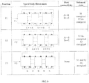
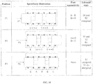
- FIG. 1 depicts a standard valve spool and body geometry. Specifically, as depicted in FIG.
- the valve spool of a typical directional-control valve incorporates three lobes, while the valve body of a typical directional-control valve incorporates five ports, which correspond to four distinct fluid ports, which are the supply (S), exhaust (E), and first and second actuator ports (A and B, respectively).
- the inlet port (S) is in fluid communication with the second actuator port (B)
- the exhaust port (E) is in fluid communication with the first actuator port (A).
- the valve spool slides to the second position (P2) the inlet port (S) is in fluid communication with the first actuator port (A), and the exhaust port (E) is in fluid communication with the second actuator port (B).
- the valve spool is commonly (though not universally) moved within the valve body between the first and second spool positions by a single solenoid actuator.
- the solenoid actuation can either be configured to be a direct-acting type, in which a solenoid actuator exerts a motive force directly on the valve spool, or of the pilot-actuated type, in which the solenoid actuator controls a pilot valve, which in turn controls the flow of a pressurized fluid, which in turn exerts motive force on the valve spool. The latter is in effect a mechanism of force amplification.
- valve In the case of a two-position valve, the valve is often actuated by a single solenoid actuator.
- solenoid actuator In the direct-acting type, energizing the solenoid actuator pushes the spool directly into the first position, while de-energizing the solenoid allows a return spring (or a similar return mechanism) to push the spool back to the second spool position.
- energizing the solenoid typically opens a pilot valve, which in turn enables a supply of pressurized fluid to fill a small cylinder adjacent to the spool and push the spool into the first position.
- De-energizing the solenoid de-pressurizes the pilot cylinder and allows a return spring (or a similar return mechanism) to push the spool back to the second spool position.
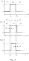
- the solenoid states associated with the two positions of a typical directional control valve are shown in FIG. 1 .
- the solenoid command corresponding to these states is illustrated in FIG. 2 , where a solenoid command (S) of one corresponds to energizing the single solenoid, and a command of zero corresponds to de-energizing the solenoid.
- the valve includes a third position of the spool within the valve body, which is physically located in an intermediate position approximately halfway between the first and second positions of the spool relative to the valve body.
- the third position is characterized by a different type of fluid connectivity relative to the first and second positions.
- all inlet and actuator ports might be isolated (i.e., none of the four ports are in fluid communication with each other), or both actuator ports might be connected to an exhaust port.
- Valves that provide the two fundamental positions, in addition to a third intermediate position, are called three-position directional-control valves.
- the valve is actuated by a pair of opposing solenoid actuators, such that energizing one solenoid while de-energizing the other moves the spool into the first position; reversing this pattern moves the spool into the second position; and de-energizing both solenoids allows a pair of centering springs to move the spool to the third, intermediate position.
- a pilot-operated valve operates similarly.
- the solenoid states associated with these three positions are shown in FIG. 3 . Note that the first and second spool positions provide the same port connectivity as the respective first and second spool positions in the two-position valve, while the third position provides a third type of port connectivity (which can have various purposes, depending on the application).
- the solenoid commands corresponding to the three spool positions of the double-solenoid valve are illustrated in FIG. 4 , where the two solenoid commands, S1 and S2, correspond to the first and second solenoid, respectively.
- a command value of one corresponds to energizing the respective solenoid, while a command value of zero corresponds to de-energizing the respective solenoid.
- GB 784 097 discloses a double-solenoid directional control valve in accordance with the preamble of claim 1.
- Exemplary embodiments of the present disclosure comprise a double-solenoid, three-position directional control valve that can operate from the electrical command intended to operate a single-solenoid, two-position valve, for specialized applications in which the third spool position is desired momentarily, when the spool is moved between the first and second spool positions.
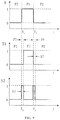
- the solenoid commands corresponding to a cyclic movement from the second spool position (P2) to the first spool position (P1), and back to the second position (P2) for the respective valves are shown in FIG. 5A .
- the bottom two plots in the figure show the normalized solenoid voltages (S1 and S2) for the first and second solenoids, respectively, required to provide the same movement between P1 and P2, with the additional energy-saving functionality.
- the shaded portion of the bottom figure (S2) indicates a fundamental problem with the use of the standard three-position configuration for purposes of obtaining equivalent functionality with the double-solenoid valve using the single-solenoid valve command.
- the second solenoid In order to maintain the double-solenoid three-position valve spool in the second position (P2), the second solenoid must be energized (as per FIGS.
- the electrical solenoid command to the single-solenoid valve is zero (i.e., the single solenoid of the valve is normally de-energized to maintain the second spool position), and thus no electrical power is present from the single-solenoid command to energize S2 in the three-position valve.
- a fundamental discrepancy exists between the electrical power requirements to maintain the second spool position in a single-solenoid and double-solenoid type directional control valves.
- Exemplary embodiments of the present disclosure comprise alternate configurations of a three-position double-solenoid directional control valve that circumvents this issue (requiring sustained electrical energy when none is present), and thus enables a double-solenoid three-position valve to function with the electrical command corresponding to a typical single-solenoid two-position valve.
- the present invention refers to a double-solenoid directional control valve comprising: a valve body; a first solenoid actuator; a second solenoid actuator; and a valve spool within the valve body, wherein the valve spool is configured to move within the valve body between a first position, a second position and a third position, where the third spool position lies between the first and second spool positions, and where the spool is maintained in the first and third positions by energizing at least the first or the second solenoid actuator, and where the spool is maintained in the second position by de-energizing both the first and the second solenoid actuators and where
- the first and second solenoid actuators are configured as pilot-operated type solenoid actuators, characterized in that one of the first or second solenoid controls a normally-closed pilot valve and the other solenoid controls a normally-open pilot valve.
- Particular embodiments further comprise a set of centering springs configured to maintain the spool in the third position in the absence of pressurization from the normally-closed pilot valve or the normally-open pilot valve.
- energizing both the first and second solenoids pressurizes the first pilot and maintains the valve spool in the first position.
- de-energizing both the first and second solenoids pressurizes the second pilot and maintains the valve spool in the second position.
- de-energizing the first solenoid and energizing the second solenoid de-pressurizes both pilots, and allows the centering springs to maintain the valve spool in the third position.
- the valve is operated by a single electrical input, which is high (energized) when the spool is commanded to the first position, and low (de-energized) when the spool is commanded to the second position.
- a high electrical input energizes both the first and second solenoids and maintains the spool in the first position.
- electrical energy from the single electrical input is stored in the valve when the spool is in the first position.
- At least one of a capacitor, a supercapacitor, or a battery is used to store electrical energy.
- stored electrical energy supplies power to temporarily energize at least one of the solenoid actuators.
- the stored electrical energy is used to energize the second solenoid actuator for a prescribed interval of time, which maintains the spool in the third position.
- only the second solenoid is initially energized for a prescribed period of time, which maintains the spool in the third position.
- the first solenoid is energized only after the second solenoid has been energized for a prescribed interval of time.
- the solenoid actuation is of the direct-acting type.
- at least one spring maintains the spool in the second position.
- energizing at least one solenoid maintains the spool in the first position.
- energizing at least one solenoid maintains the spool in the third position.
- the valve is operated by a single electrical input, which is either high (energized) or low (de-energized).
- electrical energy from the single electrical input is stored when the input is high.
- at least one of a capacitor, supercapacitor, or battery is used to store electrical energy.
- the stored electrical energy supplies power to energize at least one solenoid for a prescribed interval of time.
- only one solenoid is initially energized for a prescribed interval of time.
- the de-energized solenoid is energized after the energized solenoid has been energized for a prescribed interval of time.
- the lack of electrical power required to operate the three-position energy-saving valve can be circumvented by employing alternate actuation configurations for the three-position valve.
- de-energizing both solenoids allows a set of centering biasing members (e . g ., springs) to maintain the spool into the third (centered) spool position.
- This application proposes alternate actuation configurations for a three-position double-solenoid valve in which de-energizing both solenoids instead maintains the spool in the second (non-centered) spool position.
- the pilot-operated embodiment described here employs one solenoid that controls a normally-closed pilot, and one solenoid that controls a normally-open pilot.
- the three-position valve described here can be configured such that the first solenoid (S1) controls a normally-closed pilot valve, while the second solenoid (S2) controls a normal-open pilot valve.
- An electrical schematic of a circuit 100 that may be used in exemplary embodiments to control a single-solenoid two position valve is shown in FIG. 5B .
- the labels S, S1, and S2 correspond to the same (voltage levels) shown in FIGS. 5 , 7 , 9 and 11 .
- circuit 100 comprises a switching logic block 105.
- FIGS. 5-11 describe different strategies for the switching logic block 105.
- circuit 100 also comprises a first solenoid actuator 110, a second solenoid actuator 120, a capacitor 130.
- capacitor 130 may be configured as a capacitor, supercapacitor or battery.
- circuit 100 further comprises a regulator 140 and a voltage divider 150.
- regulator 140 and voltage divider 150 can be used to provide different voltage levels to different components in the circuit.
- the solenoid command voltage is 24 volts
- the logic circuitry voltage is 5 volts or 3.3 volts.
- the circuit logic can be implemented in a microcontroller, including for example, a small 8-bit microcontroller to implement the switching logic.
- FIG. 6 and FIG. 7 In contrast with the continuous unmet energy requirement to maintain P2 (indicated in FIG. 5A ), the configuration of FIG. 6 and FIG. 7 requires only a small, finite amount of actuation energy over a short period of time that is not directly supplied by the electrical source, corresponding to the period of dwell when the spool transits from the first to the second spool positions. Specifically, the shaded portion of FIG. 7 indicates the region of operation in which the solenoid S2 must be energized in the absence of direct electrical power from the standard single-solenoid electrical command.
- the dwell time ( ⁇ T) is short (on the order of tens to hundreds of milliseconds)
- the total energy required per cycle in this configuration is small, and can be provided by an energy storage methodology, such as a standard electrical capacitor, supercapacitor, or small rechargeable battery.
- this alternate configuration double-solenoid valve enables a method of operating the special case of a three-position valve described here (i.e., that dwells for a short period of time in the third position when moving between the first and second spool positions) that maintains electrical compatibility with a two-position single-solenoid valve command.
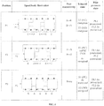
- FIG. 8 One such configuration of solenoid actuation for the three-position valve is illustrated in FIG. 8 .
- the first position is maintained by energizing only the S1 solenoid against a return spring;
- the second position is maintained by de-energizing both the S1 and S2 solenoids, allowing the return mechanism (e.g., springs) to maintain the spool in the second position;
- the third position is maintained by energizing only the S2 solenoid against the return spring.
- the solenoid commands required in this configuration, relative to a two-position standard command are shown in FIG. 9 , where the shaded portion of this figure indicates the region of operation in which the solenoid S2 must be energized in the absence of direct electrical power from the standard single-solenoid valve command.
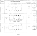
- the first position is maintained by energizing both the S1 and S2 solenoids against a return spring; the second position is maintained by de-energizing both the S1 and S2 solenoids, allowing the return spring (or springs) to maintain the spool position; and the third position is maintained by energizing only the S1 solenoid against the return spring (or springs) to maintain the third position.
- the solenoid commands required in this configuration, relative to a two-position standard command, are shown in FIG. 11 .
- the shaded portion of the figure indicates the region of operation in which the solenoid S1 must be energized in the absence of direct electrical power from the standard single-solenoid valve command.
Landscapes
- Engineering & Computer Science (AREA)
- General Engineering & Computer Science (AREA)
- Mechanical Engineering (AREA)
- Physics & Mathematics (AREA)
- Fluid Mechanics (AREA)
- Electromagnetism (AREA)
- Chemical & Material Sciences (AREA)
- Analytical Chemistry (AREA)
- Magnetically Actuated Valves (AREA)
- Electromagnets (AREA)
Description
- The present invention relates generally to double-solenoid directional control valves. The present disclosure relates more specifically to methods for actuating a double-solenoid three-position directional control valve using the electrical input intended for a single-solenoid two-position directional control valve.
- A typical directional-control valve is comprised of a valve spool that slides linearly within a valve body. The valve spool is comprised of a discrete number of lobes, typically three, while the valve body is comprised of a discrete number of internal and external ports, typically five. As the valve spool slides linearly through the valve body, various ports in the valve body are covered or exposed by the lobes of the valve spool, which in effect provides various configurations of connectivity between the ports in the valve body.
FIG. 1 depicts a standard valve spool and body geometry. Specifically, as depicted inFIG. 1 , the valve spool of a typical directional-control valve incorporates three lobes, while the valve body of a typical directional-control valve incorporates five ports, which correspond to four distinct fluid ports, which are the supply (S), exhaust (E), and first and second actuator ports (A and B, respectively). As shown in the figure, when the valve spool is in the first position (PI), the inlet port (S) is in fluid communication with the second actuator port (B), and the exhaust port (E) is in fluid communication with the first actuator port (A). When the valve spool slides to the second position (P2), the inlet port (S) is in fluid communication with the first actuator port (A), and the exhaust port (E) is in fluid communication with the second actuator port (B). These are the two fundamental positions of a directional-control valve, and valves that provide these two positions (P1 and P2) exclusively are called two-position directional-control valves. - In a two-position valve, the valve spool is commonly (though not universally) moved within the valve body between the first and second spool positions by a single solenoid actuator. The solenoid actuation can either be configured to be a direct-acting type, in which a solenoid actuator exerts a motive force directly on the valve spool, or of the pilot-actuated type, in which the solenoid actuator controls a pilot valve, which in turn controls the flow of a pressurized fluid, which in turn exerts motive force on the valve spool. The latter is in effect a mechanism of force amplification.
- In the case of a two-position valve, the valve is often actuated by a single solenoid actuator. In the direct-acting type, energizing the solenoid actuator pushes the spool directly into the first position, while de-energizing the solenoid allows a return spring (or a similar return mechanism) to push the spool back to the second spool position. In the pilot-operated type, energizing the solenoid typically opens a pilot valve, which in turn enables a supply of pressurized fluid to fill a small cylinder adjacent to the spool and push the spool into the first position. De-energizing the solenoid de-pressurizes the pilot cylinder and allows a return spring (or a similar return mechanism) to push the spool back to the second spool position. The solenoid states associated with the two positions of a typical directional control valve are shown in
FIG. 1 . The solenoid command corresponding to these states (for a two-position, single-solenoid valve) is illustrated inFIG. 2 , where a solenoid command (S) of one corresponds to energizing the single solenoid, and a command of zero corresponds to de-energizing the solenoid. - In some embodiments of a directional-control valve, the valve includes a third position of the spool within the valve body, which is physically located in an intermediate position approximately halfway between the first and second positions of the spool relative to the valve body. The third position is characterized by a different type of fluid connectivity relative to the first and second positions. For example, in the third position, all inlet and actuator ports might be isolated (i.e., none of the four ports are in fluid communication with each other), or both actuator ports might be connected to an exhaust port. Valves that provide the two fundamental positions, in addition to a third intermediate position, are called three-position directional-control valves.
- In the case of a three-position valve, the valve is actuated by a pair of opposing solenoid actuators, such that energizing one solenoid while de-energizing the other moves the spool into the first position; reversing this pattern moves the spool into the second position; and de-energizing both solenoids allows a pair of centering springs to move the spool to the third, intermediate position. A pilot-operated valve operates similarly. The solenoid states associated with these three positions are shown in
FIG. 3 . Note that the first and second spool positions provide the same port connectivity as the respective first and second spool positions in the two-position valve, while the third position provides a third type of port connectivity (which can have various purposes, depending on the application). Although the figure depicts the third-position connectivity as the case of isolating all ports, multiple possibilities exist for third-position port connectivity, and thus the third-position connectivity shown in the figure is merely for illustrative purposes. The solenoid commands corresponding to the three spool positions of the double-solenoid valve are illustrated inFIG. 4 , where the two solenoid commands, S1 and S2, correspond to the first and second solenoid, respectively. A command value of one corresponds to energizing the respective solenoid, while a command value of zero corresponds to de-energizing the respective solenoid. -
GB 784 097 claim 1. - Exemplary embodiments of the present disclosure comprise a double-solenoid, three-position directional control valve that can operate from the electrical command intended to operate a single-solenoid, two-position valve, for specialized applications in which the third spool position is desired momentarily, when the spool is moved between the first and second spool positions.
- Specifically, in some applications, one may wish to replace a two-position directional-control valve with a three-position directional-control valve. Further, in some applications, one may also desire to use the three-position valve in a manner such that the valve spool remains in the third position only momentarily, when moving between the first and the second spool positions. For the special case of such applications, it is further desirable to replace the (single-solenoid) two-position valve with the (double-solenoid) three-position valve without altering the original electrical command intended for the single-solenoid valve. Replacing a single-solenoid valve with a double-solenoid valve, however, creates a mismatch between the electrical power requirements needed to achieve the first and second spool position in each respective valve. In particular, as shown in
FIG. 2 , the single-solenoid, two-position valve maintains spool position P2 in the absence of an electrical input energizing the solenoid; conversely, as shown inFIG. 4 , the double-solenoid, three-position valve requires an energized solenoid to maintain spool position P2. In the absence of a source of solenoid energy, the three-position valve will remain in spool position P3. - For the previously described standard configurations illustrated in
FIGS. 1-2 and3-4 , respectively, the solenoid commands corresponding to a cyclic movement from the second spool position (P2) to the first spool position (P1), and back to the second position (P2) for the respective valves are shown inFIG. 5A . Specifically, the top plot in the figure shows the normalized solenoid voltage (S) as a function of time for a single-solenoid, two-position directional control valve, where the spool is commanded to move from P2 to P1 at t=T1, and commanded to move from P1 to P2 at at t=T2. The bottom two plots in the figure show the normalized solenoid voltages (S1 and S2) for the first and second solenoids, respectively, required to provide the same movement between P1 and P2, with the additional energy-saving functionality. The shaded portion of the bottom figure (S2) indicates a fundamental problem with the use of the standard three-position configuration for purposes of obtaining equivalent functionality with the double-solenoid valve using the single-solenoid valve command. In order to maintain the double-solenoid three-position valve spool in the second position (P2), the second solenoid must be energized (as perFIGS. 3 and4 ); however, in this case, the electrical solenoid command to the single-solenoid valve is zero (i.e., the single solenoid of the valve is normally de-energized to maintain the second spool position), and thus no electrical power is present from the single-solenoid command to energize S2 in the three-position valve. As such, a fundamental discrepancy exists between the electrical power requirements to maintain the second spool position in a single-solenoid and double-solenoid type directional control valves. Exemplary embodiments of the present disclosure comprise alternate configurations of a three-position double-solenoid directional control valve that circumvents this issue (requiring sustained electrical energy when none is present), and thus enables a double-solenoid three-position valve to function with the electrical command corresponding to a typical single-solenoid two-position valve. - The present invention refers to a double-solenoid directional control valve comprising: a valve body; a first solenoid actuator; a second solenoid actuator; and a valve spool within the valve body, wherein the valve spool is configured to move within the valve body between a first position, a second position and a third position, where the third spool position lies between the first and second spool positions, and where the spool is maintained in the first and third positions by energizing at least the first or the second solenoid actuator, and where the spool is maintained in the second position by de-energizing both the first and the second solenoid actuators and where
- the first and second solenoid actuators are configured as pilot-operated type solenoid actuators, characterized in that one of the first or second solenoid controls a normally-closed pilot valve and the other solenoid controls a normally-open pilot valve. Particular embodiments further comprise a set of centering springs configured to maintain the spool in the third position in the absence of pressurization from the normally-closed pilot valve or the normally-open pilot valve. In certain embodiments, energizing both the first and second solenoids pressurizes the first pilot and maintains the valve spool in the first position. In specific embodiments, de-energizing both the first and second solenoids pressurizes the second pilot and maintains the valve spool in the second position.
- In particular embodiments, de-energizing the first solenoid and energizing the second solenoid de-pressurizes both pilots, and allows the centering springs to maintain the valve spool in the third position.
- In certain embodiments, the valve is operated by a single electrical input, which is high (energized) when the spool is commanded to the first position, and low (de-energized) when the spool is commanded to the second position. In particular embodiments, a high electrical input energizes both the first and second solenoids and maintains the spool in the first position. In specific embodiments, electrical energy from the single electrical input is stored in the valve when the spool is in the first position.
- In certain embodiments, at least one of a capacitor, a supercapacitor, or a battery is used to store electrical energy. In specific embodiments, upon a transition of the single electrical input from high to low, stored electrical energy supplies power to temporarily energize at least one of the solenoid actuators. In particular embodiments, upon a transition of the single electrical input from high to low, the stored electrical energy is used to energize the second solenoid actuator for a prescribed interval of time, which maintains the spool in the third position. In certain embodiments, upon a transition of the single electrical input from low to high, only the second solenoid is initially energized for a prescribed period of time, which maintains the spool in the third position. In specific embodiments, upon a
transition of the single electrical input from low to high, the first solenoid is energized only after the second solenoid has been energized for a prescribed interval of time. - In particular examples not forming part of the invention, the solenoid actuation is of the direct-acting type. In certain examples, in the absence of solenoid actuation, at least one spring maintains the spool in the second position. In certain examples, energizing at least one solenoid maintains the spool in the first position. In specific examples, energizing at least one solenoid maintains the spool in the third position. In particular examples, the valve is operated by a single electrical input, which is either high (energized) or low (de-energized).
- In certain examples, electrical energy from the single electrical input is stored when the input is high. In particular examples, at least one of a capacitor, supercapacitor, or battery is used to store electrical energy. In specific examples, upon a transition of the single electrical input from high to low, the stored electrical energy supplies power to energize at least one solenoid for a prescribed interval of time. In certain examples, upon a transition of the single electrical input from low to high, only one solenoid is initially energized for a prescribed interval of time. In particular examples, upon a transition of the single electrical input from low to high, the de-energized solenoid is energized after the energized solenoid has been energized for a prescribed interval of time.
- The following drawings form part of the present specification and are included to further demonstrate certain aspects of the present disclosure. The disclosure may be better understood by reference to one or more of these drawings in combination with the detailed description of specific embodiments presented herein.
-
FIG. 1 depicts typical single-solenoid, two-position four-way directional control valve states. -
FIG. 2 depicts solenoid command (versus time) corresponding to first and second spool positions in a single-solenoid two-position directional control valve. A solenoid command of one corresponds to energizing the solenoid, while a command of zero corresponds to de-energizing the solenoid. -
FIG. 3 depicts three spool positions and corresponding solenoid commands corresponding to typical three-position directional control valve with typical (either pilot-operated or direct-acting) double-solenoid actuation. -
FIG. 4 depict solenoid commands (versus time) corresponding to first and second solenoids, corresponding to first, second, and third spool positions in a typical double-solenoid three-position directional control valve -
FIG. 5A depicts solenoid command corresponding to single-solenoid two-position valve (S), and corresponding solenoid commands (S1 and S2) required for same cycle of actuator reversal for energy-saving valve with a conventional double-solenoid configuration. The shaded areas correspond to regions in which the double-solenoid configuration requires electrical energy (i.e., requires that one of the solenoids be energized), but no electrical energy is directly available from the single-solenoid command. -
FIG. 5B depicts an electrical schematic of a circuit that may be used in exemplary embodiments to control a single-solenoid two position valve. -
FIG. 6 depicts three positions of a pilot-operated energy-saving directional control valve with an alternate double-solenoid configuration, where S1 controls a normally-closed (NC) pilot valve and S2 controls a normally-open (NO) pilot valve. The symbols PL1 and PL2 correspond to the first and second valve pilots, respectively. -
FIG. 7 depicts solenoid commands corresponding to actuator reversal for a single-solenoid two-position valve (S), and corresponding required solenoid commands (SI and S2) for actuator reversal for energy saving valve with alternate double-solenoid configuration. The shaded portion indicates the region of operation in which the solenoid S2 must be energized in the absence of direct electrical power from the standard single-solenoid valve command. -
FIG. 8 depicts a first example of alternate double-solenoid three-position valve configuration, not forming part of the invention. -
FIG. 9 depicts solenoid commands corresponding to actuator reversal in single-solenoid two-position valve (S), and corresponding required solenoid commands (S1 and S2) required for actuator reversal in first example of an alternate double-solenoid configuration of three-position valve. The shaded portion indicates the region of operation in which the solenoid S2 must be energized in the absence of direct electrical power from the standard single-solenoid command. -
FIG. 10 depicts a second example of alternate double-solenoid three-position valve configuration, not forming part of the invention. -
FIG. 11 depicts solenoid commands corresponding to actuator reversal in single-solenoid two-position valve (S), and corresponding required solenoid commands (S1 and S2) required for actuator reversal in second example of an alternate double-solenoid configuration of three-position valve. The shaded portion indicates the region of operation in which the solenoid S1 must be energized in the absence of direct electrical power from the standard single-solenoid valve command. - The lack of electrical power required to operate the three-position energy-saving valve can be circumvented by employing alternate actuation configurations for the three-position valve. Specifically, in a standard three-position double-solenoid valve (e.g.,
FIG. 3 ), de-energizing both solenoids allows a set of centering biasing members (e.g., springs) to maintain the spool into the third (centered) spool position. This application proposes alternate actuation configurations for a three-position double-solenoid valve in which de-energizing both solenoids instead maintains the spool in the second (non-centered) spool position. - Consider first the case of a pilot-operated double-solenoid valve. In such a valve, rather than move the spool directly, the solenoid actuators control fluid connectivity to a pilot fluid supply, which in turn moves the spool by pressurizing the first or second end of the spool. In a conventional solenoid-actuated pilot-operated valve, energizing only the first solenoid opens a first normally-closed pilot valve, which in turn uses the pressurized gas in the pilot to push the spool into the first position. Similarly, energizing only the second solenoid opens a second normally-closed pilot valve, which in turn uses the pressurized gas in the pilot to push the spool (back) into the second position. De-energizing both solenoids closes both pilot valves (i.e., depressurizes both sides of the spool), and allows the centering springs to move the spool into the third (centered) position.
- Rather than use both solenoids to control normally-closed pilot valves (as in the conventional case), the pilot-operated embodiment described here employs one solenoid that controls a normally-closed pilot, and one solenoid that controls a normally-open pilot. For example, the three-position valve described here can be configured such that the first solenoid (S1) controls a normally-closed pilot valve, while the second solenoid (S2) controls a normal-open pilot valve. An electrical schematic of a
circuit 100 that may be used in exemplary embodiments to control a single-solenoid two position valve is shown inFIG. 5B . InFIG. 5B , the labels S, S1, and S2 correspond to the same (voltage levels) shown inFIGS. 5 ,7 ,9 and11 . In the embodiment shown,circuit 100 comprises a switchinglogic block 105.FIGS. 5-11 describe different strategies for the switchinglogic block 105. - As shown in
FIG. 5B ,circuit 100 also comprises afirst solenoid actuator 110, asecond solenoid actuator 120, acapacitor 130. In certain embodiments,capacitor 130 may be configured as a capacitor, supercapacitor or battery. In the embodiment shown,circuit 100 further comprises aregulator 140 and a voltage divider 150. In certain embodiments,regulator 140 and voltage divider 150 can be used to provide different voltage levels to different components in the circuit. For example, in certain embodiments, the solenoid command voltage is 24 volts, while the logic circuitry voltage is 5 volts or 3.3 volts. - In specific embodiments, the circuit logic can be implemented in a microcontroller, including for example, a small 8-bit microcontroller to implement the switching logic.
- In this case, energizing both solenoids will open the first pilot and close the second, thus maintaining the spool in the first position; de-energizing both solenoids will shut off the first pilot and open the second, thus maintaining the spool in the second position; and de-energizing the first solenoid and energizing the second will shut off both pilot supplies and allow the centering springs to maintain the spool in the third position. This configuration is outlined in
FIG. 6 . Assuming this configuration, the solenoid valve commands for the first and second solenoids (S1 and S2) corresponding to a cycle of actuator reversal are shown inFIG. 7 , relative to the corresponding single solenoid valve command (S) for the same actuator reversal. - In contrast with the continuous unmet energy requirement to maintain P2 (indicated in
FIG. 5A ), the configuration ofFIG. 6 andFIG. 7 requires only a small, finite amount of actuation energy over a short period of time that is not directly supplied by the electrical source, corresponding to the period of dwell when the spool transits from the first to the second spool positions. Specifically, the shaded portion ofFIG. 7 indicates the region of operation in which the solenoid S2 must be energized in the absence of direct electrical power from the standard single-solenoid electrical command. Since the dwell time (ΔT) is short (on the order of tens to hundreds of milliseconds), the total energy required per cycle in this configuration is small, and can be provided by an energy storage methodology, such as a standard electrical capacitor, supercapacitor, or small rechargeable battery. - Specifically, since this temporary energy is required in the transition from the first to the second position, and since the first position is associated with direct electrical power supplied by the standard single-solenoid command, energy supplied during this state can be stored electrically and used to energize the second solenoid for the brief period of dwell immediately following the directly energized state. Thus, this alternate configuration double-solenoid valve enables a method of operating the special case of a three-position valve described here (i.e., that dwells for a short period of time in the third position when moving between the first and second spool positions) that maintains electrical compatibility with a two-position single-solenoid valve command.
- Consider now the case of a double-solenoid valve that moves the spool via direct solenoid actuation (i.e., without pilot operation). In a conventional direct-acting solenoid-actuated valve, energizing only the first solenoid pulls the core of the solenoid into a coil, which directly pushes the spool into the first position. Similarly, energizing only the second solenoid directly pushes the spool (back) into the second position. De-energizing both solenoids allows a set of centering springs to move the spool into the third (centered) position. In this configuration, the relationship of solenoid actuation and spool position is identical to the conventional pilot-operated case (illustrated in
FIG. 6 ), and as such the electrical requirements relative to the command for a two-position single-solenoid valve are the same as well, as illustrated byFIG. 5A (i.e., a continuous unmet electrical energy requirement in order to maintain the spool in the second position). In order to make the double-solenoid valve compatible with the command for a single-solenoid valve, two alternate solenoid configurations are described here. Both are characterized by a spool return mechanism (e.g., return springs) that maintains the spool in the second position when both solenoid actuators are de-energized. That is, unlike the conventional three-position configuration, maintaining the spool in the third (centered) spool position requires that at least one solenoid actuator is energized. - One such configuration of solenoid actuation for the three-position valve is illustrated in
FIG. 8 . In this first example, the first position is maintained by energizing only the S1 solenoid against a return spring; the second position is maintained by de-energizing both the S1 and S2 solenoids, allowing the return mechanism (e.g., springs) to maintain the spool in the second position; and the third position is maintained by energizing only the S2 solenoid against the return spring. The solenoid commands required in this configuration, relative to a two-position standard command, are shown inFIG. 9 , where the shaded portion of this figure indicates the region of operation in which the solenoid S2 must be energized in the absence of direct electrical power from the standard single-solenoid valve command. - In a second alternate example, illustrated in
FIG. 10 , the first position is maintained by energizing both the S1 and S2 solenoids against a return spring; the second position is maintained by de-energizing both the S1 and S2 solenoids, allowing the return spring (or springs) to maintain the spool position; and the third position is maintained by energizing only the S1 solenoid against the return spring (or springs) to maintain the third position. The solenoid commands required in this configuration, relative to a two-position standard command, are shown inFIG. 11 . The shaded portion of the figure indicates the region of operation in which the solenoid S1 must be energized in the absence of direct electrical power from the standard single-solenoid valve command.
Claims (11)
- A double-solenoid directional control valve comprising:a valve body;a first solenoid actuator (110);a second solenoid actuator (120); anda valve spool within the valve body, wherein:the valve spool is configured to move within the valve body between a first position, a second position and a third position, where the third spool position lies between the first and second spool positions, and where the spool is maintained in the first and third positions by energizing at least the first or the second solenoid actuator, and where the spool is maintained in the second position by de-energizing both the first and the second solenoid actuators,characterized in that the first and second solenoid actuators are configured as pilot-operated type solenoid actuators, where one of the first or second solenoid controls a normally-closed pilot valve and the other solenoid controls a normally-open pilot valve.
- The valve of claim 1, further comprising a set of centering springs configured to maintain the spool in the third position in the absence of pressurization from the normally-closed pilot valve or the normally-open pilot valve.
- The valve of claim 2, where energizing both the first and second solenoids pressurizes the first pilot and maintains the valve spool in the first position.
- The valve of claim 2, where de-energizing both the first and second solenoids pressurizes the second pilot and maintains the valve spool in the second position.
- The valve of claim 2, where de-energizing the first solenoid and energizing the second solenoid de-pressurizes both pilots, and allows the centering springs to maintain the valve spool in the third position.
- The valve of claim 5, wherein the valve is operated by a single electrical input, which is high, i.e. energized, when the spool is commanded to the first position, and low, i.e. de-energized, when the spool is commanded to the second position.
- The valve of claim 6, wherein a high electrical input energizes both the first and second solenoids and maintains the spool in the first position.
- The valve of claim 6, where electrical energy from the single electrical input is stored in the valve when the spool is in the first position.
- The valve of claim 8, where at least one of a capacitor, a supercapacitor, or a battery is used to store electrical energy.
- The valve of claim 8, where upon a transition of the single electrical input from high to low, stored electrical energy supplies power to temporarily energize at least one of the solenoid actuators, in particular where upon a transition of the single electrical input from high to low, the stored electrical energy is used to energize the second solenoid actuator for a prescribed interval of time, which maintains the spool in the third position.
- The valve of claim 6, where upon a transition of the single electrical input from low to high, only the second solenoid is initially energized for a prescribed period of time, which maintains the spool in the third position, or where upon a transition of the single electrical input from low to high, the first solenoid is energized only after the second solenoid has been energized for a prescribed interval of time.
Applications Claiming Priority (2)
| Application Number | Priority Date | Filing Date | Title |
|---|---|---|---|
| US201261747619P | 2012-12-31 | 2012-12-31 | |
| PCT/US2013/078433 WO2014106230A1 (en) | 2012-12-31 | 2013-12-31 | Directional control valve with double-solenoid configurations |
Publications (2)
| Publication Number | Publication Date |
|---|---|
| EP2938886A1 EP2938886A1 (en) | 2015-11-04 |
| EP2938886B1 true EP2938886B1 (en) | 2018-12-05 |
Family
ID=50029232
Family Applications (1)
| Application Number | Title | Priority Date | Filing Date |
|---|---|---|---|
| EP13824725.9A Not-in-force EP2938886B1 (en) | 2012-12-31 | 2013-12-31 | Directional control valve with double-solenoid configurations |
Country Status (4)
| Country | Link |
|---|---|
| US (1) | US9964125B2 (en) |
| EP (1) | EP2938886B1 (en) |
| JP (1) | JP2016508205A (en) |
| WO (1) | WO2014106230A1 (en) |
Families Citing this family (4)
| Publication number | Priority date | Publication date | Assignee | Title |
|---|---|---|---|---|
| US20170306990A1 (en) * | 2014-10-03 | 2017-10-26 | Nexmatix Llc | Energy saving directional-control valves for providing input-output compatibility with standard non-energy saving directional-control valves |
| US11015624B2 (en) | 2016-05-19 | 2021-05-25 | Steven H. Marquardt | Methods and devices for conserving energy in fluid power production |
| ES2602329B1 (en) * | 2016-11-17 | 2017-11-29 | Bitron Industrie España, S.A. | ELECTROVALULE VALVE OF FLUID IN THREE WORKING POSITIONS |
| JP6570671B2 (en) * | 2018-02-01 | 2019-09-04 | 油研工業株式会社 | Bipolar current control drive circuit for inductive load |
Family Cites Families (13)
| Publication number | Priority date | Publication date | Assignee | Title |
|---|---|---|---|---|
| US2255617A (en) * | 1940-07-20 | 1941-09-09 | Clarence B Hoak | Annealing apparatus and method |
| GB784097A (en) * | 1955-04-27 | 1957-10-02 | Ckd Ceska Lipa | A hydraulic control system |
| US2843093A (en) * | 1955-08-16 | 1958-07-15 | Ckd Ceska Lipa Narodni Podnik | Valve means and control therefor for fluid motors |
| US2940475A (en) * | 1957-09-30 | 1960-06-14 | Galland Henning Mfg Company | Valve |
| FR2453306B1 (en) | 1979-04-06 | 1986-03-14 | Dba | FIVE-POSITION HYDRAULIC ACTUATOR |
| US5623968A (en) * | 1995-12-18 | 1997-04-29 | Ingersoll-Rand Company | Valve assembly with manually actuated valve override |
| DE19607773A1 (en) * | 1996-03-01 | 1997-09-04 | Bosch Gmbh Robert | Electromagnetically operated directional valve |
| US6021876A (en) * | 1998-08-06 | 2000-02-08 | Fema Corporation Of Michigan | Electrical proportional pressure control valve |
| US6192937B1 (en) * | 1999-04-26 | 2001-02-27 | Mac Valves, Inc. | Pilot operated pneumatic valve |
| JP2001351814A (en) * | 2000-06-07 | 2001-12-21 | Nippon Soken Inc | Electromagnetic actuator driving circuit |
| DE10247967B3 (en) | 2002-10-15 | 2004-02-05 | Festo Ag & Co. | Multi-way valve for controlling pneumatic or hydraulic drive has main valve element held in neutral position between 2 working positions for pressure equalization between load connections via pre-control stage |
| US8794123B2 (en) * | 2010-03-12 | 2014-08-05 | Ross Operating Valve Company | Double valve constructed from unitary single valves |
| JP5505843B2 (en) | 2011-04-07 | 2014-05-28 | Smc株式会社 | Pilot operated 3-position switching valve |
-
2013
- 2013-12-31 US US14/758,311 patent/US9964125B2/en active Active
- 2013-12-31 WO PCT/US2013/078433 patent/WO2014106230A1/en active Application Filing
- 2013-12-31 JP JP2015550858A patent/JP2016508205A/en active Pending
- 2013-12-31 EP EP13824725.9A patent/EP2938886B1/en not_active Not-in-force
Non-Patent Citations (1)
| Title |
|---|
| None * |
Also Published As
| Publication number | Publication date |
|---|---|
| WO2014106230A1 (en) | 2014-07-03 |
| US9964125B2 (en) | 2018-05-08 |
| EP2938886A1 (en) | 2015-11-04 |
| JP2016508205A (en) | 2016-03-17 |
| US20150354720A1 (en) | 2015-12-10 |
Similar Documents
| Publication | Publication Date | Title |
|---|---|---|
| EP2938886B1 (en) | Directional control valve with double-solenoid configurations | |
| CN202302103U (en) | Lift valve assembly and system for controlling pneumatic actuator | |
| US20100200090A1 (en) | Spool Valve | |
| CN103370565B (en) | Two-stage variable force solenoid | |
| WO2019224426A1 (en) | On/off hydraulic valve | |
| CN111749941B (en) | Pilot-operated type multi-oil-way control valve group | |
| US8857313B2 (en) | Fluid operated actuator system | |
| EP2021667B1 (en) | Electrically operated hydraulic valve | |
| US9599248B2 (en) | Directional control valve with spool delay mechanism | |
| US5836230A (en) | High speed 2-way control valve | |
| JP2017534820A (en) | Energy saving directional control valve to provide I / O compatibility with standard non-energy saving directional control valve | |
| EP2689142B1 (en) | Valve | |
| FI128357B (en) | On/off hydraulic valve | |
| CN113418025B (en) | Electro-hydraulic reversing control structure | |
| US9709180B2 (en) | Directional poppet valve | |
| US20240035492A1 (en) | Valve and aircraft | |
| JPH0245574Y2 (en) | ||
| JPS6136575A (en) | Direction change valve with manual-solenoid operation mechanism | |
| JP2010144924A (en) | Electromagnetic spool valve unit | |
| WO2008047233A2 (en) | Control valve assembly | |
| JPH053747U (en) | solenoid valve |
Legal Events
| Date | Code | Title | Description |
|---|---|---|---|
| PUAI | Public reference made under article 153(3) epc to a published international application that has entered the european phase |
Free format text: ORIGINAL CODE: 0009012 |
|
| 17P | Request for examination filed |
Effective date: 20150701 |
|
| AK | Designated contracting states |
Kind code of ref document: A1 Designated state(s): AL AT BE BG CH CY CZ DE DK EE ES FI FR GB GR HR HU IE IS IT LI LT LU LV MC MK MT NL NO PL PT RO RS SE SI SK SM TR |
|
| AX | Request for extension of the european patent |
Extension state: BA ME |
|
| DAX | Request for extension of the european patent (deleted) | ||
| 17Q | First examination report despatched |
Effective date: 20171013 |
|
| GRAP | Despatch of communication of intention to grant a patent |
Free format text: ORIGINAL CODE: EPIDOSNIGR1 |
|
| INTG | Intention to grant announced |
Effective date: 20180627 |
|
| GRAS | Grant fee paid |
Free format text: ORIGINAL CODE: EPIDOSNIGR3 |
|
| GRAA | (expected) grant |
Free format text: ORIGINAL CODE: 0009210 |
|
| AK | Designated contracting states |
Kind code of ref document: B1 Designated state(s): AL AT BE BG CH CY CZ DE DK EE ES FI FR GB GR HR HU IE IS IT LI LT LU LV MC MK MT NL NO PL PT RO RS SE SI SK SM TR |
|
| REG | Reference to a national code |
Ref country code: GB Ref legal event code: FG4D |
|
| REG | Reference to a national code |
Ref country code: CH Ref legal event code: EP |
|
| REG | Reference to a national code |
Ref country code: AT Ref legal event code: REF Ref document number: 1073443 Country of ref document: AT Kind code of ref document: T Effective date: 20181215 |
|
| REG | Reference to a national code |
Ref country code: DE Ref legal event code: R096 Ref document number: 602013047903 Country of ref document: DE |
|
| REG | Reference to a national code |
Ref country code: IE Ref legal event code: FG4D |
|
| REG | Reference to a national code |
Ref country code: NL Ref legal event code: MP Effective date: 20181205 |
|
| REG | Reference to a national code |
Ref country code: AT Ref legal event code: MK05 Ref document number: 1073443 Country of ref document: AT Kind code of ref document: T Effective date: 20181205 |
|
| REG | Reference to a national code |
Ref country code: LT Ref legal event code: MG4D |
|
| PG25 | Lapsed in a contracting state [announced via postgrant information from national office to epo] |
Ref country code: FI Free format text: LAPSE BECAUSE OF FAILURE TO SUBMIT A TRANSLATION OF THE DESCRIPTION OR TO PAY THE FEE WITHIN THE PRESCRIBED TIME-LIMIT Effective date: 20181205 Ref country code: ES Free format text: LAPSE BECAUSE OF FAILURE TO SUBMIT A TRANSLATION OF THE DESCRIPTION OR TO PAY THE FEE WITHIN THE PRESCRIBED TIME-LIMIT Effective date: 20181205 Ref country code: BG Free format text: LAPSE BECAUSE OF FAILURE TO SUBMIT A TRANSLATION OF THE DESCRIPTION OR TO PAY THE FEE WITHIN THE PRESCRIBED TIME-LIMIT Effective date: 20190305 Ref country code: HR Free format text: LAPSE BECAUSE OF FAILURE TO SUBMIT A TRANSLATION OF THE DESCRIPTION OR TO PAY THE FEE WITHIN THE PRESCRIBED TIME-LIMIT Effective date: 20181205 Ref country code: LV Free format text: LAPSE BECAUSE OF FAILURE TO SUBMIT A TRANSLATION OF THE DESCRIPTION OR TO PAY THE FEE WITHIN THE PRESCRIBED TIME-LIMIT Effective date: 20181205 Ref country code: NO Free format text: LAPSE BECAUSE OF FAILURE TO SUBMIT A TRANSLATION OF THE DESCRIPTION OR TO PAY THE FEE WITHIN THE PRESCRIBED TIME-LIMIT Effective date: 20190305 Ref country code: LT Free format text: LAPSE BECAUSE OF FAILURE TO SUBMIT A TRANSLATION OF THE DESCRIPTION OR TO PAY THE FEE WITHIN THE PRESCRIBED TIME-LIMIT Effective date: 20181205 Ref country code: AT Free format text: LAPSE BECAUSE OF FAILURE TO SUBMIT A TRANSLATION OF THE DESCRIPTION OR TO PAY THE FEE WITHIN THE PRESCRIBED TIME-LIMIT Effective date: 20181205 |
|
| PG25 | Lapsed in a contracting state [announced via postgrant information from national office to epo] |
Ref country code: AL Free format text: LAPSE BECAUSE OF FAILURE TO SUBMIT A TRANSLATION OF THE DESCRIPTION OR TO PAY THE FEE WITHIN THE PRESCRIBED TIME-LIMIT Effective date: 20181205 Ref country code: RS Free format text: LAPSE BECAUSE OF FAILURE TO SUBMIT A TRANSLATION OF THE DESCRIPTION OR TO PAY THE FEE WITHIN THE PRESCRIBED TIME-LIMIT Effective date: 20181205 Ref country code: GR Free format text: LAPSE BECAUSE OF FAILURE TO SUBMIT A TRANSLATION OF THE DESCRIPTION OR TO PAY THE FEE WITHIN THE PRESCRIBED TIME-LIMIT Effective date: 20190306 Ref country code: SE Free format text: LAPSE BECAUSE OF FAILURE TO SUBMIT A TRANSLATION OF THE DESCRIPTION OR TO PAY THE FEE WITHIN THE PRESCRIBED TIME-LIMIT Effective date: 20181205 |
|
| PG25 | Lapsed in a contracting state [announced via postgrant information from national office to epo] |
Ref country code: NL Free format text: LAPSE BECAUSE OF FAILURE TO SUBMIT A TRANSLATION OF THE DESCRIPTION OR TO PAY THE FEE WITHIN THE PRESCRIBED TIME-LIMIT Effective date: 20181205 |
|
| REG | Reference to a national code |
Ref country code: DE Ref legal event code: R119 Ref document number: 602013047903 Country of ref document: DE |
|
| PG25 | Lapsed in a contracting state [announced via postgrant information from national office to epo] |
Ref country code: PT Free format text: LAPSE BECAUSE OF FAILURE TO SUBMIT A TRANSLATION OF THE DESCRIPTION OR TO PAY THE FEE WITHIN THE PRESCRIBED TIME-LIMIT Effective date: 20190405 Ref country code: CZ Free format text: LAPSE BECAUSE OF FAILURE TO SUBMIT A TRANSLATION OF THE DESCRIPTION OR TO PAY THE FEE WITHIN THE PRESCRIBED TIME-LIMIT Effective date: 20181205 Ref country code: IT Free format text: LAPSE BECAUSE OF FAILURE TO SUBMIT A TRANSLATION OF THE DESCRIPTION OR TO PAY THE FEE WITHIN THE PRESCRIBED TIME-LIMIT Effective date: 20181205 Ref country code: PL Free format text: LAPSE BECAUSE OF FAILURE TO SUBMIT A TRANSLATION OF THE DESCRIPTION OR TO PAY THE FEE WITHIN THE PRESCRIBED TIME-LIMIT Effective date: 20181205 |
|
| REG | Reference to a national code |
Ref country code: CH Ref legal event code: PL |
|
| PG25 | Lapsed in a contracting state [announced via postgrant information from national office to epo] |
Ref country code: SM Free format text: LAPSE BECAUSE OF FAILURE TO SUBMIT A TRANSLATION OF THE DESCRIPTION OR TO PAY THE FEE WITHIN THE PRESCRIBED TIME-LIMIT Effective date: 20181205 Ref country code: EE Free format text: LAPSE BECAUSE OF FAILURE TO SUBMIT A TRANSLATION OF THE DESCRIPTION OR TO PAY THE FEE WITHIN THE PRESCRIBED TIME-LIMIT Effective date: 20181205 Ref country code: LU Free format text: LAPSE BECAUSE OF NON-PAYMENT OF DUE FEES Effective date: 20181231 Ref country code: SK Free format text: LAPSE BECAUSE OF FAILURE TO SUBMIT A TRANSLATION OF THE DESCRIPTION OR TO PAY THE FEE WITHIN THE PRESCRIBED TIME-LIMIT Effective date: 20181205 Ref country code: RO Free format text: LAPSE BECAUSE OF FAILURE TO SUBMIT A TRANSLATION OF THE DESCRIPTION OR TO PAY THE FEE WITHIN THE PRESCRIBED TIME-LIMIT Effective date: 20181205 Ref country code: IS Free format text: LAPSE BECAUSE OF FAILURE TO SUBMIT A TRANSLATION OF THE DESCRIPTION OR TO PAY THE FEE WITHIN THE PRESCRIBED TIME-LIMIT Effective date: 20190405 |
|
| REG | Reference to a national code |
Ref country code: BE Ref legal event code: MM Effective date: 20181231 Ref country code: IE Ref legal event code: MM4A |
|
| PLBE | No opposition filed within time limit |
Free format text: ORIGINAL CODE: 0009261 |
|
| STAA | Information on the status of an ep patent application or granted ep patent |
Free format text: STATUS: NO OPPOSITION FILED WITHIN TIME LIMIT |
|
| PG25 | Lapsed in a contracting state [announced via postgrant information from national office to epo] |
Ref country code: IE Free format text: LAPSE BECAUSE OF NON-PAYMENT OF DUE FEES Effective date: 20181231 Ref country code: DE Free format text: LAPSE BECAUSE OF NON-PAYMENT OF DUE FEES Effective date: 20190702 Ref country code: SI Free format text: LAPSE BECAUSE OF FAILURE TO SUBMIT A TRANSLATION OF THE DESCRIPTION OR TO PAY THE FEE WITHIN THE PRESCRIBED TIME-LIMIT Effective date: 20181205 Ref country code: FR Free format text: LAPSE BECAUSE OF NON-PAYMENT OF DUE FEES Effective date: 20190205 Ref country code: MC Free format text: LAPSE BECAUSE OF FAILURE TO SUBMIT A TRANSLATION OF THE DESCRIPTION OR TO PAY THE FEE WITHIN THE PRESCRIBED TIME-LIMIT Effective date: 20181205 Ref country code: DK Free format text: LAPSE BECAUSE OF FAILURE TO SUBMIT A TRANSLATION OF THE DESCRIPTION OR TO PAY THE FEE WITHIN THE PRESCRIBED TIME-LIMIT Effective date: 20181205 |
|
| 26N | No opposition filed |
Effective date: 20190906 |
|
| GBPC | Gb: european patent ceased through non-payment of renewal fee |
Effective date: 20190305 |
|
| PG25 | Lapsed in a contracting state [announced via postgrant information from national office to epo] |
Ref country code: BE Free format text: LAPSE BECAUSE OF NON-PAYMENT OF DUE FEES Effective date: 20181231 |
|
| PG25 | Lapsed in a contracting state [announced via postgrant information from national office to epo] |
Ref country code: LI Free format text: LAPSE BECAUSE OF NON-PAYMENT OF DUE FEES Effective date: 20181231 Ref country code: CH Free format text: LAPSE BECAUSE OF NON-PAYMENT OF DUE FEES Effective date: 20181231 |
|
| PG25 | Lapsed in a contracting state [announced via postgrant information from national office to epo] |
Ref country code: GB Free format text: LAPSE BECAUSE OF NON-PAYMENT OF DUE FEES Effective date: 20190305 Ref country code: MT Free format text: LAPSE BECAUSE OF NON-PAYMENT OF DUE FEES Effective date: 20181231 |
|
| PG25 | Lapsed in a contracting state [announced via postgrant information from national office to epo] |
Ref country code: TR Free format text: LAPSE BECAUSE OF FAILURE TO SUBMIT A TRANSLATION OF THE DESCRIPTION OR TO PAY THE FEE WITHIN THE PRESCRIBED TIME-LIMIT Effective date: 20181205 |
|
| PG25 | Lapsed in a contracting state [announced via postgrant information from national office to epo] |
Ref country code: MK Free format text: LAPSE BECAUSE OF NON-PAYMENT OF DUE FEES Effective date: 20181205 Ref country code: HU Free format text: LAPSE BECAUSE OF FAILURE TO SUBMIT A TRANSLATION OF THE DESCRIPTION OR TO PAY THE FEE WITHIN THE PRESCRIBED TIME-LIMIT; INVALID AB INITIO Effective date: 20131231 Ref country code: CY Free format text: LAPSE BECAUSE OF FAILURE TO SUBMIT A TRANSLATION OF THE DESCRIPTION OR TO PAY THE FEE WITHIN THE PRESCRIBED TIME-LIMIT Effective date: 20181205 |