EP2938860B1 - Turbinenabgasgehäuse mit mehrteiligem rahmen - Google Patents
Turbinenabgasgehäuse mit mehrteiligem rahmen Download PDFInfo
- Publication number
- EP2938860B1 EP2938860B1 EP13866645.8A EP13866645A EP2938860B1 EP 2938860 B1 EP2938860 B1 EP 2938860B1 EP 13866645 A EP13866645 A EP 13866645A EP 2938860 B1 EP2938860 B1 EP 2938860B1
- Authority
- EP
- European Patent Office
- Prior art keywords
- radial
- turbine exhaust
- exhaust case
- strut
- fairing
- Prior art date
- Legal status (The legal status is an assumption and is not a legal conclusion. Google has not performed a legal analysis and makes no representation as to the accuracy of the status listed.)
- Active
Links
- 238000007789 sealing Methods 0.000 claims description 8
- PXHVJJICTQNCMI-UHFFFAOYSA-N Nickel Chemical compound [Ni] PXHVJJICTQNCMI-UHFFFAOYSA-N 0.000 claims description 6
- 239000000463 material Substances 0.000 claims description 6
- 238000000034 method Methods 0.000 claims description 5
- 229910052759 nickel Inorganic materials 0.000 claims description 3
- 229910000601 superalloy Inorganic materials 0.000 claims description 3
- 229910000831 Steel Inorganic materials 0.000 claims description 2
- 239000010959 steel Substances 0.000 claims description 2
- 229910001208 Crucible steel Inorganic materials 0.000 description 2
- 230000005465 channeling Effects 0.000 description 2
- 238000013459 approach Methods 0.000 description 1
- 238000002485 combustion reaction Methods 0.000 description 1
- 238000010276 construction Methods 0.000 description 1
- 239000000284 extract Substances 0.000 description 1
- 239000000446 fuel Substances 0.000 description 1
- 229910001026 inconel Inorganic materials 0.000 description 1
- 238000009434 installation Methods 0.000 description 1
- 230000013011 mating Effects 0.000 description 1
- 239000000203 mixture Substances 0.000 description 1
- 238000012986 modification Methods 0.000 description 1
- 230000004048 modification Effects 0.000 description 1
- 230000002459 sustained effect Effects 0.000 description 1
- 238000003466 welding Methods 0.000 description 1
Images


Classifications
-
- F—MECHANICAL ENGINEERING; LIGHTING; HEATING; WEAPONS; BLASTING
- F01—MACHINES OR ENGINES IN GENERAL; ENGINE PLANTS IN GENERAL; STEAM ENGINES
- F01D—NON-POSITIVE DISPLACEMENT MACHINES OR ENGINES, e.g. STEAM TURBINES
- F01D25/00—Component parts, details, or accessories, not provided for in, or of interest apart from, other groups
- F01D25/30—Exhaust heads, chambers, or the like
-
- F—MECHANICAL ENGINEERING; LIGHTING; HEATING; WEAPONS; BLASTING
- F01—MACHINES OR ENGINES IN GENERAL; ENGINE PLANTS IN GENERAL; STEAM ENGINES
- F01D—NON-POSITIVE DISPLACEMENT MACHINES OR ENGINES, e.g. STEAM TURBINES
- F01D1/00—Non-positive-displacement machines or engines, e.g. steam turbines
- F01D1/18—Non-positive-displacement machines or engines, e.g. steam turbines without stationary working-fluid guiding means
-
- F—MECHANICAL ENGINEERING; LIGHTING; HEATING; WEAPONS; BLASTING
- F01—MACHINES OR ENGINES IN GENERAL; ENGINE PLANTS IN GENERAL; STEAM ENGINES
- F01D—NON-POSITIVE DISPLACEMENT MACHINES OR ENGINES, e.g. STEAM TURBINES
- F01D25/00—Component parts, details, or accessories, not provided for in, or of interest apart from, other groups
- F01D25/16—Arrangement of bearings; Supporting or mounting bearings in casings
- F01D25/162—Bearing supports
-
- F—MECHANICAL ENGINEERING; LIGHTING; HEATING; WEAPONS; BLASTING
- F01—MACHINES OR ENGINES IN GENERAL; ENGINE PLANTS IN GENERAL; STEAM ENGINES
- F01D—NON-POSITIVE DISPLACEMENT MACHINES OR ENGINES, e.g. STEAM TURBINES
- F01D25/00—Component parts, details, or accessories, not provided for in, or of interest apart from, other groups
- F01D25/24—Casings; Casing parts, e.g. diaphragms, casing fastenings
- F01D25/243—Flange connections; Bolting arrangements
-
- Y—GENERAL TAGGING OF NEW TECHNOLOGICAL DEVELOPMENTS; GENERAL TAGGING OF CROSS-SECTIONAL TECHNOLOGIES SPANNING OVER SEVERAL SECTIONS OF THE IPC; TECHNICAL SUBJECTS COVERED BY FORMER USPC CROSS-REFERENCE ART COLLECTIONS [XRACs] AND DIGESTS
- Y10—TECHNICAL SUBJECTS COVERED BY FORMER USPC
- Y10T—TECHNICAL SUBJECTS COVERED BY FORMER US CLASSIFICATION
- Y10T29/00—Metal working
- Y10T29/49—Method of mechanical manufacture
- Y10T29/49316—Impeller making
- Y10T29/4932—Turbomachine making
- Y10T29/49323—Assembling fluid flow directing devices, e.g., stators, diaphragms, nozzles
Definitions
- the present disclosure relates generally to gas turbine engines, and more particularly to heat management in a turbine exhaust case of a gas turbine engine.
- a turbine exhaust case is a structural frame that supports engine bearing loads while providing a gas path at or near the aft end of a gas turbine engine.
- Some aeroengines utilize a turbine exhaust case to help mount the gas turbine engine to an aircraft airframe.
- a turbine exhaust case is more commonly used to couple gas turbine engines to a power turbine that powers an electrical generator.
- Industrial turbine exhaust cases may, for instance, be situated between a low pressure engine turbine and a generator power turbine.
- a turbine exhaust case must bear shaft loads from interior bearings, and must be capable of sustained operation at high temperatures.
- Turbine exhaust cases serve two primary purposes: airflow channeling and structural support.
- Turbine exhaust cases typically comprise structures with inner and outer rings connected by radial struts.
- the struts and rings often define a core flow path from fore to aft, while simultaneously mechanically supporting shaft bearings situated axially inward of the inner ring.
- the components of a turbine exhaust case are exposed to very high temperatures along the core flow path.
- Various approaches and architectures have been employed to handle these high temperatures.
- Some turbine exhaust case frames utilize high-temperature, high-stress capable materials to both define the core flow path and bear mechanical loads.
- Other turbine exhaust case architectures separate these two functions, pairing a structural frame for mechanical loads with a high-temperature capable fairing to define the core flow path.
- Fairings are typically constructed as a "ship in a bottle,” built piece-by-piece within a unitary frame.
- Some fairing embodiments for instance, comprise suction and pressure side pieces of fairing vanes for each frame strut. These pieces are inserted individually inside the structural frame, and joined together (e.g. by welding) to surround frame struts.
- a prior art turbine exhaust case is disclosed in US 2010/0303608 A1 .
- a prior art mid turbine frame is disclosed in US 2010/0132376 A1 .
- the present invention provides a turbine exhaust case as recited in claim 1, and a method of assembling a turbine exhaust case as recited in claim 11.
- FIG. 1 is a simplified partial cross-sectional view of gas turbine engine 10, comprising inlet 12, compressor 14 (with low pressure compressor 16 and high pressure compressor 18), combustor 20, engine turbine 22 (with high pressure turbine 24 and low pressure turbine 26), turbine exhaust case 28, power turbine 30, low pressure shaft 32, high pressure shaft 34, and power shaft 36.
- Gas turbine engine 10 can, for instance, be an industrial power turbine.
- Low pressure shaft 32, high pressure shaft 34, and power shaft 36 are situated along rotational axis A.
- low pressure shaft 32 and high pressure shaft 34 are arranged concentrically, while power shaft 36 is disposed axially aft of low pressure shaft 32 and high pressure shaft 34.
- Low pressure shaft 32 defines a low pressure spool including low pressure compressor 16 and low pressure turbine 26.
- High pressure shaft 34 analogously defines a high pressure spool including high pressure compressor 18 and high pressure compressor 24.
- airflow F is received at inlet 12, then pressurized by low pressure compressor 16 and high pressure compressor 18.
- Fuel is injected at combustor 20, where the resulting fuel-air mixture is ignited.
- Expanding combustion gasses rotate high pressure turbine 24 and low pressure turbine 26, thereby driving high and low pressure compressors 18 and 16 through high pressure shaft 34 and low pressure shaft 32, respectively.
- compressor 14 and engine turbine 22 are depicted as two-spool components with high and low sections on separate shafts, single spool or three or more spool embodiments of compressor 14 and engine turbine 22 are also possible.
- Turbine exhaust case 28 carries airflow from low pressure turbine 26 to power turbine 30, where this airflow drives power shaft 36.
- Power shaft 36 can, for instance, drive an electrical generator, pump, mechanical gearbox, or other accessory (not shown).
- turbine exhaust case 28 can support one or more shaft loads.
- Turbine exhaust case 28 can, for instance, support low pressure shaft 32 via bearing compartments (not shown) disposed to communicate load from low pressure shaft 32 to a structural frame of turbine exhaust case 28.
- FIG. 2 is a simplified cross-sectional view of one embodiment of turbine exhaust case 28, labeled turbine exhaust case 28a.
- FIG. 2 illustrates low pressure turbine 26 (with low pressure turbine casing 42, low pressure vane 36, low pressure rotor blade 38, and low pressure rotor disk 40) and power turbine 30 (with power turbine case 52, power turbine vanes 46, power turbine rotor blades 48, and power turbine rotor disks 50), and turbine exhaust case 28a (with frame 100a, outer ring 102a, inner ring 104, strut 106a, inner radial strut fasteners 108, outer cover 110a, chordwise expandable diameter fastener 112, circumferentially-oriented expandable diameter fasteners 114a, fairing 116, outer platform 118, inner platform 120, fairing vane 122, and frame boss 126a).
- low pressure turbine 26 is an engine turbine connected to low pressure compressor 16 via low pressure shaft 32.
- Low pressure turbine rotor blades 38 are axially stacked collections of circumferentially distributed airfoils anchored to low pressure turbine rotor disk 40. Although only one low pressure turbine rotor disk 40 and a single representative low pressure turbine rotor blade 38 are shown, low pressure turbine 26 may comprise any number of rotor stages interspersed with low pressure rotor vanes 36.
- Low pressure rotor vanes 36 are airfoil surfaces that channel flow F to impart aerodynamic loads on low pressure rotor blades 38, thereby driving low pressure shaft 32 (see FIG. 1 ).
- Low pressure turbine case 42 is a rigid outer surface of low pressure turbine 26 that carries radial and axial load from low pressure turbine components, e.g. to turbine exhaust case 28.
- Power turbine 30 parallels low pressure turbine 26, but extracts energy from airflow F to drive a generator, pump, mechanical gearbox, or similar device, rather than to power compressor 14. Like low pressure turbine 26, power turbine 30 operates by channeling airflow through alternating stages of airfoil vanes and blades. Power turbine vanes 46 channel airflow F to rotate power turbine rotor blades 48 on power turbine rotor disks 50.
- Turbine exhaust case 28 is an intermediate structure connecting low pressure turbine 26 to power turbine 30.
- Turbine exhaust case 28 may for instance be anchored to low pressure turbine 26 and power turbine 30 via bolts, pins, rivets, or screws.
- turbine exhaust case 28 may serve as an attachment point for installation mounting hardware (e.g. trusses, posts) that supports not only turbine exhaust case 28, but also low pressure turbine 26, power turbine 30, and/or other components of gas turbine engine 10.
- Turbine exhaust case 28 comprises two primary components: frame 100, which supports structural loads including shaft loads e.g. from low pressure shaft 32, and fairing 116, which defines an aerodynamic flow path from low pressure turbine 26 to power turbine 30.
- Fairing 116 can be formed in a unitary, monolithic piece, while frame 100 is assembled about fairing 116.
- Fairing vane 122 is an aerodynamic vane surface surrounding strut 106a. Fairing 116 can have any number of fairing vanes 122 at least equal to the number of struts 106a. In one embodiment, fairing 116 has one vane fairing 122 for each strut 106a of frame 100. In other embodiments, fairing 116 may include additional vane fairings 122 through which no strut 106a passes. Fairing 120 can be formed of a high temperature capable material such as Inconel or another nickel-based superalloy.
- Frame 100 is a multi-piece frame comprising three distinct types of structural components, plus connecting fasteners.
- the outer diameter of frame 100 is formed by outer ring 100a, a substantially frustoconical annulus with strut boss 126a, a radially outward-extending hollow boss that carries chordwise expandable diameter fasteners 112 and circumferentially-oriented expandable diameter fasteners 114a for securing strut 106a.
- Chordwise expandable diameter fasteners 112 and circumferentially-oriented expandable diameter fasteners 114a may, for instance, be expandable diameter bolts, shafts, or pins capable of extending entirely through both strut 106a and strut boss 126a, and expanding to take in corresponding tolerances and account for thermal drift.
- Chordwise expandable diameter fasteners 112 extend substantially axially through strut boss 126a and strut 106a, while circumferentially-extending expandable diameter fasteners 114a extend circumferentially through strut boss 126a and strut 106a, and are secured on either angular side of strut boss 126a.
- circumferentially-extending expandable diameter fasteners 114a may be situated at more than one radial location with respect to axis A.
- Strut bosses 126a have strut apertures SA at their radially outer extents to receive struts 106a.
- Strut apertures S A can be sealed by covers 110a.
- cover 110a is a flat lid secured over strut aperture S A .
- the inner diameter of frame 100 is defined by inner ring 104, a substantially cylindrical structure with inner radial strut fasteners 108.
- Inner radial strut fasteners 108 may, for instance, be screws, pins, or bolts extending radially inward through inner ring 104 and into strut 106a to secure strut 106a at its radially inner extent to inner ring 104.
- inner radial strut fasteners 108 may be radial posts extending radially inward from inner ring 106a, and mating with corresponding post holes at the inner diameter of strut 106a.
- Struts 106a are rigid posts extending substantially radially from inner ring 104, through fairing vanes 122, into strut bosses 126a. Struts 106a are anchored in all dimensions by the combination of chordwise expandable diameter fasteners 112 and circumferentially-oriented expandable diameter fasteners 114a. Frame 100 is not directly exposed to core flow F, and therefore can be formed of a material rated to significantly lower temperatures than fairing 120. In some embodiments, frame 100 may be formed of sand-cast steel.
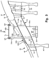
- FIG. 3 is a simplified cross-sectional view of an alternative embodiment of turbine exhaust case 28, labeled turbine exhaust case 28b.
- FIG. 2 illustrates low pressure turbine 26 (with low pressure turbine casing 42, low pressure vane 36, low pressure rotor blade 38, and low pressure rotor disk 40) and power turbine 30 (with power turbine case 52, power turbine vanes 46, power turbine rotor blades 48, and power turbine rotor disks 50), and turbine exhaust case 28b (with frame 100b, outer ring 102b, inner ring 104, strut 106b, inner radial strut fasteners 108, outer cover 110b, circumferentially-oriented expandable diameter fasteners 114b, fairing 116, outer platform 118, inner platform 120, fairing vane 122, and cover fasteners 124, and strut boss 126b).
- Turbine exhaust case 28b differs from turbine exhaust case 28a only in frame 100b, outer ring 102b, cover 110b, circumferentially-oriented expandable diameter fasteners 114b, and cover fasteners 124; in every other way the embodiments depicted in FIGs. 2 and 3 are identical.
- Frame 100b differs from frame 100a in that strut boss 126b includes no apertures for chordwise expandable diameter fasteners.
- Strut 106a is secured solely by circumferentially-extending expandable diameter fasteners 114b in strut boss 126b, and need extend as far radially as strut 106a.
- Cover 110b is a sealing plate secured in an airtight seal over strut aperture S A by cover fasteners 124, which may for instance be bolts, pins, rivets, or screws.
- Turbine exhaust case 28 is assembled by axially and circumferentially aligning fairing 120 with inner ring 104 and outer ring 102, and slotting each strut 106 through strut aperture S A and fairing vane 126 from radially outside onto inner radial strut fasteners 108.
- inner radial strut fasteners 108 can then be secured to the inner diameter of strut 106.
- Circumferentially-oriented expandable diameter fasteners 114 and chordwise expandable diameter fasteners 112, in the embodiment of FIG.
- fairing 116 can be a single, monolithically formed piece, e.g. a unitary die-cast body with no weak points corresponding to weld or other joint locations.
- the turbine exhaust case of the present invention can optionally include, additionally and/or alternatively, any one or more of the following features, configurations, and/or additional components:
- the method of the present invention can optionally include, additionally and/or alternatively, any one or more of the following features, configurations, and/or additional components: further comprising covering the sealing aperture with an airtight sealing plate.
Landscapes
- Engineering & Computer Science (AREA)
- Mechanical Engineering (AREA)
- General Engineering & Computer Science (AREA)
- Turbine Rotor Nozzle Sealing (AREA)
Claims (12)
- Turbinenabgasgehäuse (28), umfassend:eine Verkleidung (116), die einen Luftströmungsweg durch das Turbinenabgasgehäuse (28) definiert; undeinen mehrteiligen Rahmen (100), der durch und um die Verkleidung (116) herum angeordnet ist, um eine Lagerlast zu tragen, wobei der mehrteilige Rahmen (100) Folgendes umfasst:einen inneren Ring (104);einen äußeren kegelstumpfförmigen Ring (100a), der konzentrisch außerhalb des inneren Rings (104) angeordnet ist und über offene Ansätze (126a;126b) an Positionen von Streben verfügt; undeine Mehrzahl von radialen Streben (106a), die durch die Verkleidung (116) und in die offenen Ansätze (126a; 126b) des äußeren kegelstumpfförmigen Rings (100a) verläuft, und die am inneren Ring (104) über radiale Befestigungselemente (108) befestigt sind, und über nichtradiale Befestigungselemente mit erweiterbarem Durchmesser (112, 114a; 114b) am offenen Ansatz (126a, 126b) befestigt sind.
- Turbinenabgasgehäuse nach Anspruch 1, wobei der mehrteilige Rahmen (100) aus Stahl gebildet ist.
- Turbinenabgasgehäuse nach Anspruch 1 oder 2, wobei die Verkleidung (116) monolithisch gebildet ist.
- Turbinenabgasgehäuse nach Anspruch 1, 2 oder 3, wobei die Verkleidung (116) aus einem Material gebildet ist, das für eine höhere Temperatur als der mehrteilige Rahmen bemessen ist.
- Turbinenabgasgehäuse nach einem der vorhergehenden Ansprüche, wobei die Verkleidung (116) aus einer nickelbasierten Superlegierung gebildet ist.
- Turbinenabgasgehäuse nach einem der vorhergehenden Ansprüche, ferner umfassend luftdichte Dichtplatten (110a; 110b), die jeden offenen Ansatz (126a; 126b) abdecken.
- Turbinenabgasgehäuse nach Anspruch 6, wobei die Dichtplatten (110a; 110b) die äußeren radialen Erstreckungen jedes offenen Ansatzes (126a; 126b) abdecken.
- Turbinenabgasgehäuse nach einem der vorhergehenden Ansprüche, wobei die nichtradialen Befestigungselemente ein Befestigungselement mit in Umfangsrichtung orientiertem, erweiterbarem Durchmesser (114a; 114b) umfassen.
- Turbinenabgasgehäuse nach Anspruch 8, wobei die nichtradialen Befestigungselemente mindestens ein Befestigungselement mit in Sehnenrichtung orientiertem, erweiterbarem Durchmesser (112) umfassen.
- Turbinenabgasgehäuse nach einem der vorhergehenden Ansprüche, wobei die radialen Befestigungselemente (108) radiale Bolzen umfassen, die sich durch den inneren Ring (104) und in die radialen Streben (106a) erstrecken.
- Verfahren zum Zusammenbauen eines Turbinenabgasgehäuses (28), das Verfahren umfassend:Ausrichten von Verkleidungsschaufeln (122) einer einen Strömungsweg definierenden Verkleidung (116), radialen Befestigungselementen (108) auf einem inneren Rahmenring (104) und Strebenöffnungen (SA) in einem Strebenansatz (126a; 126b) eines äußeren kegelstumpfförmigen Rings (100a);Einführen einer radialen Strebe (106a) von radial außerhalb des äußeren kegelstumpfförmigen Rings (100a) durch die Strebenöffnung (SA) und die Verkleidungsschaufel (122) ;Befestigen der radialen Strebe (106a) am inneren Rahmenring (104) über die radialen Befestigungselemente (108); undBefestigen der radialen Strebe (106a) am Strebenansatz (126a; 126b) über nichtradiale Befestigungselemente mit erweiterbarem Durchmesser (112, 114a; 114b).
- Verfahren nach Anspruch 11, ferner umfassend das Abdecken der Dichtungsöffnung (SA) mit einer luftdichten Dichtplatte (110a; 110b).
Applications Claiming Priority (2)
| Application Number | Priority Date | Filing Date | Title |
|---|---|---|---|
| US201261747817P | 2012-12-31 | 2012-12-31 | |
| PCT/US2013/076872 WO2014105688A1 (en) | 2012-12-31 | 2013-12-20 | Turbine exhaust case multi-piece frame |
Publications (3)
| Publication Number | Publication Date |
|---|---|
| EP2938860A1 EP2938860A1 (de) | 2015-11-04 |
| EP2938860A4 EP2938860A4 (de) | 2016-03-23 |
| EP2938860B1 true EP2938860B1 (de) | 2018-08-29 |
Family
ID=51021992
Family Applications (1)
| Application Number | Title | Priority Date | Filing Date |
|---|---|---|---|
| EP13866645.8A Active EP2938860B1 (de) | 2012-12-31 | 2013-12-20 | Turbinenabgasgehäuse mit mehrteiligem rahmen |
Country Status (3)
| Country | Link |
|---|---|
| US (1) | US9890663B2 (de) |
| EP (1) | EP2938860B1 (de) |
| WO (1) | WO2014105688A1 (de) |
Families Citing this family (13)
| Publication number | Priority date | Publication date | Assignee | Title |
|---|---|---|---|---|
| US20160186614A1 (en) * | 2014-08-27 | 2016-06-30 | United Technologies Corporation | Turbine exhaust case assembly |
| GB2551777B (en) | 2016-06-30 | 2018-09-12 | Rolls Royce Plc | A stator vane arrangement and a method of casting a stator vane arrangement |
| GB201612293D0 (en) * | 2016-07-15 | 2016-08-31 | Rolls Royce Plc | Assembly for supprting an annulus |
| DE102017212311A1 (de) | 2017-07-19 | 2019-01-24 | MTU Aero Engines AG | Umströmungsanordung zum Anordnen im Heißgaskanal einer Strömungsmaschine |
| US10781721B2 (en) * | 2018-02-09 | 2020-09-22 | General Electric Company | Integral turbine center frame |
| GB201903782D0 (en) * | 2019-03-20 | 2019-05-01 | Rolls Royce Plc | A bearing support structure |
| US10954802B2 (en) | 2019-04-23 | 2021-03-23 | Rolls-Royce Plc | Turbine section assembly with ceramic matrix composite vane |
| US11008880B2 (en) | 2019-04-23 | 2021-05-18 | Rolls-Royce Plc | Turbine section assembly with ceramic matrix composite vane |
| US10975708B2 (en) | 2019-04-23 | 2021-04-13 | Rolls-Royce Plc | Turbine section assembly with ceramic matrix composite vane |
| US11193393B2 (en) | 2019-04-23 | 2021-12-07 | Rolls-Royce Plc | Turbine section assembly with ceramic matrix composite vane |
| US11149559B2 (en) | 2019-05-13 | 2021-10-19 | Rolls-Royce Plc | Turbine section assembly with ceramic matrix composite vane |
| US11572793B2 (en) | 2019-07-29 | 2023-02-07 | Pratt & Whitney Canada Corp. | Gas turbine engine exhaust case |
| US11732596B2 (en) | 2021-12-22 | 2023-08-22 | Rolls-Royce Plc | Ceramic matrix composite turbine vane assembly having minimalistic support spars |
Citations (1)
| Publication number | Priority date | Publication date | Assignee | Title |
|---|---|---|---|---|
| US3710674A (en) * | 1970-12-18 | 1973-01-16 | Meteor Res Ltd | Expandable fastener |
Family Cites Families (152)
| Publication number | Priority date | Publication date | Assignee | Title |
|---|---|---|---|---|
| US2214108A (en) | 1938-11-05 | 1940-09-10 | Gen Motors Corp | Manufacture of tubing |
| US4044555A (en) | 1958-09-30 | 1977-08-30 | Hayes International Corporation | Rear section of jet power plant installations |
| US3576328A (en) | 1968-03-22 | 1971-04-27 | Robert W Vose | High pressure seals |
| US3802046A (en) | 1972-01-27 | 1974-04-09 | Chromalloy American Corp | Method of making or reconditioning a turbine-nozzle or the like assembly |
| US3970319A (en) | 1972-11-17 | 1976-07-20 | General Motors Corporation | Seal structure |
| US3877762A (en) | 1974-03-19 | 1975-04-15 | United Aircraft Corp | Turbine rear bearing support structure |
| US4022948A (en) | 1974-12-23 | 1977-05-10 | United Technologies Corporation | Resiliently coated metallic finger seals |
| US4009569A (en) | 1975-07-21 | 1977-03-01 | United Technologies Corporation | Diffuser-burner casing for a gas turbine engine |
| US4088422A (en) | 1976-10-01 | 1978-05-09 | General Electric Company | Flexible interstage turbine spacer |
| US4369016A (en) | 1979-12-21 | 1983-01-18 | United Technologies Corporation | Turbine intermediate case |
| US4321007A (en) | 1979-12-21 | 1982-03-23 | United Technologies Corporation | Outer case cooling for a turbine intermediate case |
| US4305697A (en) | 1980-03-19 | 1981-12-15 | General Electric Company | Method and replacement member for repairing a gas turbine engine vane assembly |
| US4478551A (en) | 1981-12-08 | 1984-10-23 | United Technologies Corporation | Turbine exhaust case design |
| GB8504331D0 (en) | 1985-02-20 | 1985-03-20 | Rolls Royce | Brush seals |
| US4645217A (en) | 1985-11-29 | 1987-02-24 | United Technologies Corporation | Finger seal assembly |
| GB2198195B (en) | 1986-12-06 | 1990-05-16 | Rolls Royce Plc | Brush seal |
| US5246295A (en) | 1991-10-30 | 1993-09-21 | Ide Russell D | Non-contacting mechanical face seal of the gap-type |
| US4793770A (en) | 1987-08-06 | 1988-12-27 | General Electric Company | Gas turbine engine frame assembly |
| US4738453A (en) | 1987-08-17 | 1988-04-19 | Ide Russell D | Hydrodynamic face seal with lift pads |
| US4920742A (en) | 1988-05-31 | 1990-05-01 | General Electric Company | Heat shield for gas turbine engine frame |
| US4987736A (en) | 1988-12-14 | 1991-01-29 | General Electric Company | Lightweight gas turbine engine frame with free-floating heat shield |
| US4989406A (en) | 1988-12-29 | 1991-02-05 | General Electric Company | Turbine engine assembly with aft mounted outlet guide vanes |
| US4993918A (en) | 1989-05-19 | 1991-02-19 | United Technologies Corporation | Replaceable fairing for a turbine exhaust case |
| US4979872A (en) * | 1989-06-22 | 1990-12-25 | United Technologies Corporation | Bearing compartment support |
| US5071138A (en) | 1989-12-21 | 1991-12-10 | Allied-Signal Inc. | Laminated finger seal |
| US5031922A (en) | 1989-12-21 | 1991-07-16 | Allied-Signal Inc. | Bidirectional finger seal |
| US5042823A (en) | 1989-12-21 | 1991-08-27 | Allied-Signal Inc. | Laminated finger seal |
| US5076049A (en) | 1990-04-02 | 1991-12-31 | General Electric Company | Pretensioned frame |
| US5100158A (en) | 1990-08-16 | 1992-03-31 | Eg&G Sealol, Inc. | Compliant finer seal |
| GB9020317D0 (en) | 1990-09-18 | 1990-10-31 | Cross Mfg Co | Sealing devices |
| US5108116A (en) | 1991-05-31 | 1992-04-28 | Allied-Signal Inc. | Laminated finger seal with logarithmic curvature |
| US5174584A (en) | 1991-07-15 | 1992-12-29 | General Electric Company | Fluid bearing face seal for gas turbine engines |
| US5169159A (en) | 1991-09-30 | 1992-12-08 | General Electric Company | Effective sealing device for engine flowpath |
| US5236302A (en) | 1991-10-30 | 1993-08-17 | General Electric Company | Turbine disk interstage seal system |
| US5188507A (en) | 1991-11-27 | 1993-02-23 | General Electric Company | Low-pressure turbine shroud |
| FR2685381B1 (fr) | 1991-12-18 | 1994-02-11 | Snecma | Carter de turbine delimitant une veine d'ecoulement annulaire de gaz divisee par des bras radiaux. |
| US5211541A (en) | 1991-12-23 | 1993-05-18 | General Electric Company | Turbine support assembly including turbine heat shield and bolt retainer assembly |
| US5269057A (en) | 1991-12-24 | 1993-12-14 | Freedom Forge Corporation | Method of making replacement airfoil components |
| US5265807A (en) | 1992-06-01 | 1993-11-30 | Rohr, Inc. | Aerodynamic stiffening ring for an aircraft turbine engine mixer |
| GB2267736B (en) | 1992-06-09 | 1995-08-09 | Gen Electric | Segmented turbine flowpath assembly |
| US5292227A (en) | 1992-12-10 | 1994-03-08 | General Electric Company | Turbine frame |
| US5272869A (en) | 1992-12-10 | 1993-12-28 | General Electric Company | Turbine frame |
| US5273397A (en) | 1993-01-13 | 1993-12-28 | General Electric Company | Turbine casing and radiation shield |
| US5338154A (en) | 1993-03-17 | 1994-08-16 | General Electric Company | Turbine disk interstage seal axial retaining ring |
| US5401036A (en) | 1993-03-22 | 1995-03-28 | Eg & G Sealol, Inc. | Brush seal device having a recessed back plate |
| US5483792A (en) | 1993-05-05 | 1996-01-16 | General Electric Company | Turbine frame stiffening rails |
| US5370402A (en) | 1993-05-07 | 1994-12-06 | Eg&G Sealol, Inc. | Pressure balanced compliant seal device |
| US5691279A (en) | 1993-06-22 | 1997-11-25 | The United States Of America As Represented By The Secretary Of The Army | C-axis oriented high temperature superconductors deposited onto new compositions of garnet |
| US5441385A (en) * | 1993-12-13 | 1995-08-15 | Solar Turbines Incorporated | Turbine nozzle/nozzle support structure |
| US5438756A (en) | 1993-12-17 | 1995-08-08 | General Electric Company | Method for assembling a turbine frame assembly |
| US5558341A (en) | 1995-01-11 | 1996-09-24 | Stein Seal Company | Seal for sealing an incompressible fluid between a relatively stationary seal and a movable member |
| US5632493A (en) | 1995-05-04 | 1997-05-27 | Eg&G Sealol, Inc. | Compliant pressure balanced seal apparatus |
| US5851105A (en) | 1995-06-28 | 1998-12-22 | General Electric Company | Tapered strut frame |
| DE19535945A1 (de) | 1995-09-27 | 1997-04-03 | Hydraulik Ring Gmbh | Magnetventil sowie Verfahren zu dessen Herstellung |
| US5609467A (en) | 1995-09-28 | 1997-03-11 | Cooper Cameron Corporation | Floating interturbine duct assembly for high temperature power turbine |
| US5597286A (en) | 1995-12-21 | 1997-01-28 | General Electric Company | Turbine frame static seal |
| US5605438A (en) | 1995-12-29 | 1997-02-25 | General Electric Co. | Casing distortion control for rotating machinery |
| US5634767A (en) | 1996-03-29 | 1997-06-03 | General Electric Company | Turbine frame having spindle mounted liner |
| US5755445A (en) | 1996-08-23 | 1998-05-26 | Alliedsignal Inc. | Noncontacting finger seal with hydrodynamic foot portion |
| JP3403073B2 (ja) | 1997-08-26 | 2003-05-06 | キヤノン株式会社 | シート給送装置及び画像処理装置 |
| FR2777318B1 (fr) | 1998-04-09 | 2000-05-12 | Snecma | Procede de reduction du jeu existant entre une chemise et un distributeur de turbine d'un turboreacteur |
| US6227800B1 (en) | 1998-11-24 | 2001-05-08 | General Electric Company | Bay cooled turbine casing |
| US6196550B1 (en) | 1999-02-11 | 2001-03-06 | Alliedsignal Inc. | Pressure balanced finger seal |
| US6364316B1 (en) | 1999-02-11 | 2002-04-02 | Honeywell International Inc. | Dual pressure balanced noncontacting finger seal |
| US6343912B1 (en) | 1999-12-07 | 2002-02-05 | General Electric Company | Gas turbine or jet engine stator vane frame |
| US6358001B1 (en) | 2000-04-29 | 2002-03-19 | General Electric Company | Turbine frame assembly |
| US6439841B1 (en) | 2000-04-29 | 2002-08-27 | General Electric Company | Turbine frame assembly |
| JP4410425B2 (ja) | 2001-03-05 | 2010-02-03 | 三菱重工業株式会社 | 冷却型ガスタービン排気車室 |
| US6511284B2 (en) | 2001-06-01 | 2003-01-28 | General Electric Company | Methods and apparatus for minimizing gas turbine engine thermal stress |
| JP4689882B2 (ja) | 2001-06-29 | 2011-05-25 | イーグル工業株式会社 | 板ブラシシール装置 |
| US20030025274A1 (en) | 2001-08-02 | 2003-02-06 | Honeywell International, Inc. | Laminated finger seal with stress reduction |
| JP4824225B2 (ja) | 2001-08-29 | 2011-11-30 | イーグル工業株式会社 | 板ブラシシール装置 |
| SE519781C2 (sv) | 2001-08-29 | 2003-04-08 | Volvo Aero Corp | Förfarande för framställning av en stator-eller rotorkomponent |
| JP4675530B2 (ja) | 2001-09-28 | 2011-04-27 | イーグル工業株式会社 | 板ブラシシール |
| JP4751552B2 (ja) | 2001-09-28 | 2011-08-17 | イーグル工業株式会社 | 板ブラシシールおよび板ブラシシール装置 |
| US6612807B2 (en) | 2001-11-15 | 2003-09-02 | General Electric Company | Frame hub heating system |
| US6672833B2 (en) | 2001-12-18 | 2004-01-06 | General Electric Company | Gas turbine engine frame flowpath liner support |
| US6736401B2 (en) | 2001-12-19 | 2004-05-18 | Honeywell International, Inc. | Laminated finger seal with ceramic composition |
| US6796765B2 (en) | 2001-12-27 | 2004-09-28 | General Electric Company | Methods and apparatus for assembling gas turbine engine struts |
| DE10303088B4 (de) | 2002-02-09 | 2015-08-20 | Alstom Technology Ltd. | Abgasgehäuse einer Wärmekraftmaschine |
| US6719524B2 (en) | 2002-02-25 | 2004-04-13 | Honeywell International Inc. | Method of forming a thermally isolated gas turbine engine housing |
| US6638013B2 (en) | 2002-02-25 | 2003-10-28 | Honeywell International Inc. | Thermally isolated housing in gas turbine engine |
| US6652229B2 (en) | 2002-02-27 | 2003-11-25 | General Electric Company | Leaf seal support for inner band of a turbine nozzle in a gas turbine engine |
| US6619030B1 (en) | 2002-03-01 | 2003-09-16 | General Electric Company | Aircraft engine with inter-turbine engine frame supported counter rotating low pressure turbine rotors |
| JP4054607B2 (ja) | 2002-05-23 | 2008-02-27 | イーグル工業株式会社 | 板ブラシシール |
| US7614150B2 (en) | 2002-08-14 | 2009-11-10 | Volvo Aero Corporation | Method for manufacturing a stator or rotor component |
| US7200933B2 (en) | 2002-08-14 | 2007-04-10 | Volvo Aero Corporation | Method for manufacturing a stator component |
| US6792758B2 (en) | 2002-11-07 | 2004-09-21 | Siemens Westinghouse Power Corporation | Variable exhaust struts shields |
| US6811154B2 (en) | 2003-02-08 | 2004-11-02 | The United States Of America As Represented By The Administrator Of The National Aeronautics And Space Administration | Noncontacting finger seal |
| SE525879C2 (sv) | 2003-03-21 | 2005-05-17 | Volvo Aero Corp | Förfarande för framställning av en statorkomponent |
| EP1780382A3 (de) * | 2003-07-29 | 2011-03-09 | Pratt & Whitney Canada Corp. | Turbofangehäuse und Herstellungsverfahren |
| US6983608B2 (en) | 2003-12-22 | 2006-01-10 | General Electric Company | Methods and apparatus for assembling gas turbine engines |
| US6969826B2 (en) | 2004-04-08 | 2005-11-29 | General Electric Company | Welding process |
| US7094026B2 (en) | 2004-04-29 | 2006-08-22 | General Electric Company | System for sealing an inner retainer segment and support ring in a gas turbine and methods therefor |
| US7238008B2 (en) | 2004-05-28 | 2007-07-03 | General Electric Company | Turbine blade retainer seal |
| US7100358B2 (en) | 2004-07-16 | 2006-09-05 | Pratt & Whitney Canada Corp. | Turbine exhaust case and method of making |
| US7229249B2 (en) | 2004-08-27 | 2007-06-12 | Pratt & Whitney Canada Corp. | Lightweight annular interturbine duct |
| US7367567B2 (en) | 2005-03-02 | 2008-05-06 | United Technologies Corporation | Low leakage finger seal |
| US7744709B2 (en) | 2005-08-22 | 2010-06-29 | United Technologies Corporation | Welding repair method for full hoop structures |
| FR2891301B1 (fr) | 2005-09-29 | 2007-11-02 | Snecma Sa | Carter structural de turbomoteur |
| US7371044B2 (en) | 2005-10-06 | 2008-05-13 | Siemens Power Generation, Inc. | Seal plate for turbine rotor assembly between turbine blade and turbine vane |
| FR2898641B1 (fr) | 2006-03-17 | 2008-05-02 | Snecma Sa | Habillage de carter dans un turboreacteur |
| US7677047B2 (en) | 2006-03-29 | 2010-03-16 | United Technologies Corporation | Inverted stiffened shell panel torque transmission for loaded struts and mid-turbine frames |
| US7631879B2 (en) | 2006-06-21 | 2009-12-15 | General Electric Company | “L” butt gap seal between segments in seal assemblies |
| US20100236244A1 (en) | 2006-06-28 | 2010-09-23 | Longardner Robert L | Heat absorbing and reflecting shield for air breathing heat engine |
| US7815417B2 (en) | 2006-09-01 | 2010-10-19 | United Technologies Corporation | Guide vane for a gas turbine engine |
| US20100303608A1 (en) * | 2006-09-28 | 2010-12-02 | Mitsubishi Heavy Industries, Ltd. | Two-shaft gas turbine |
| US7798768B2 (en) | 2006-10-25 | 2010-09-21 | Siemens Energy, Inc. | Turbine vane ID support |
| US7735833B2 (en) | 2006-11-14 | 2010-06-15 | The University Of Akron | Double padded finger seal |
| US7959409B2 (en) | 2007-03-01 | 2011-06-14 | Honeywell International Inc. | Repaired vane assemblies and methods of repairing vane assemblies |
| US20080216300A1 (en) | 2007-03-06 | 2008-09-11 | United Technologies Corporation | Splitter fairing repair |
| FR2914017B1 (fr) | 2007-03-20 | 2011-07-08 | Snecma | Dispositif d'etancheite pour un circuit de refroidissement, carter inter-turbine en etant equipe et turboreacteur les comportant |
| US7824152B2 (en) | 2007-05-09 | 2010-11-02 | Siemens Energy, Inc. | Multivane segment mounting arrangement for a gas turbine |
| FR2917458B1 (fr) | 2007-06-13 | 2009-09-25 | Snecma Sa | Moyeu de carter d'echappement comportant des nervures de repartition de contraintes |
| DE102007042767A1 (de) | 2007-09-07 | 2009-03-12 | Mtu Aero Engines Gmbh | Mehrschichtiger Abschirmungsring für einen Flugantrieb |
| FR2925119A1 (fr) | 2007-12-14 | 2009-06-19 | Snecma Sa | Etancheite d'une cavite de moyeu d'un carter d'echappement dans une turbomachine |
| US8312726B2 (en) | 2007-12-21 | 2012-11-20 | United Technologies Corp. | Gas turbine engine systems involving I-beam struts |
| US20110000223A1 (en) | 2008-02-25 | 2011-01-06 | Volvo Aero Corporation | gas turbine component and a method for producing a gas turbine component |
| CN101960101B (zh) | 2008-02-27 | 2014-12-31 | 三菱重工业株式会社 | 排气室的连结结构、涡轮的支撑结构以及燃气轮机 |
| WO2009157817A1 (en) | 2008-06-26 | 2009-12-30 | Volvo Aero Corporation | Vane assembly and method of fabricating, and a turbo-machine with such vane assembly |
| US8069648B2 (en) | 2008-07-03 | 2011-12-06 | United Technologies Corporation | Impingement cooling for turbofan exhaust assembly |
| WO2010002295A1 (en) | 2008-07-04 | 2010-01-07 | Volvo Aero Corporation | A welding method |
| US8083465B2 (en) | 2008-09-05 | 2011-12-27 | United Technologies Corporation | Repaired turbine exhaust strut heat shield vanes and repair methods |
| US8092161B2 (en) | 2008-09-24 | 2012-01-10 | Siemens Energy, Inc. | Thermal shield at casing joint |
| US8221071B2 (en) | 2008-09-30 | 2012-07-17 | General Electric Company | Integrated guide vane assembly |
| US20100132377A1 (en) | 2008-11-28 | 2010-06-03 | Pratt & Whitney Canada Corp. | Fabricated itd-strut and vane ring for gas turbine engine |
| US8347500B2 (en) | 2008-11-28 | 2013-01-08 | Pratt & Whitney Canada Corp. | Method of assembly and disassembly of a gas turbine mid turbine frame |
| US20100132371A1 (en) | 2008-11-28 | 2010-06-03 | Pratt & Whitney Canada Corp. | Mid turbine frame system for gas turbine engine |
| US8245518B2 (en) | 2008-11-28 | 2012-08-21 | Pratt & Whitney Canada Corp. | Mid turbine frame system for gas turbine engine |
| US8091371B2 (en) * | 2008-11-28 | 2012-01-10 | Pratt & Whitney Canada Corp. | Mid turbine frame for gas turbine engine |
| US8347635B2 (en) * | 2008-11-28 | 2013-01-08 | Pratt & Whitey Canada Corp. | Locking apparatus for a radial locator for gas turbine engine mid turbine frame |
| US8177488B2 (en) | 2008-11-29 | 2012-05-15 | General Electric Company | Integrated service tube and impingement baffle for a gas turbine engine |
| US8152451B2 (en) | 2008-11-29 | 2012-04-10 | General Electric Company | Split fairing for a gas turbine engine |
| US8371812B2 (en) | 2008-11-29 | 2013-02-12 | General Electric Company | Turbine frame assembly and method for a gas turbine engine |
| EP2379845A4 (de) | 2008-12-18 | 2013-08-07 | Gkn Aerospace Sweden Ab | Gasturbinenverbundteil zur verwendung in einem gasturbinentriebwerk |
| US8245399B2 (en) | 2009-01-20 | 2012-08-21 | United Technologies Corporation | Replacement of part of engine case with dissimilar material |
| GB2467790B (en) | 2009-02-16 | 2011-06-01 | Rolls Royce Plc | Vane |
| US20100275572A1 (en) | 2009-04-30 | 2010-11-04 | Pratt & Whitney Canada Corp. | Oil line insulation system for mid turbine frame |
| US8408011B2 (en) | 2009-04-30 | 2013-04-02 | Pratt & Whitney Canada Corp. | Structural reinforcement strut for gas turbine case |
| WO2010128900A1 (en) | 2009-05-08 | 2010-11-11 | Volvo Aero Corporation | Supporting structure for a gas turbine engine |
| US20110061767A1 (en) | 2009-09-14 | 2011-03-17 | United Technologies Corporation | Component removal tool and method |
| US8371127B2 (en) | 2009-10-01 | 2013-02-12 | Pratt & Whitney Canada Corp. | Cooling air system for mid turbine frame |
| US8740557B2 (en) | 2009-10-01 | 2014-06-03 | Pratt & Whitney Canada Corp. | Fabricated static vane ring |
| US8469661B2 (en) | 2009-10-01 | 2013-06-25 | Pratt & Whitney Canada Corp. | Fabricated gas turbine vane ring |
| US8596959B2 (en) | 2009-10-09 | 2013-12-03 | Pratt & Whitney Canada Corp. | Oil tube with integrated heat shield |
| US8776533B2 (en) | 2010-03-08 | 2014-07-15 | United Technologies Corporation | Strain tolerant bound structure for a gas turbine engine |
| CH703309A1 (de) | 2010-06-10 | 2011-12-15 | Alstom Technology Ltd | Abgasgehäuse für eine gasturbine sowie verfahren zum herstellen eines solchen abgasgehäuses. |
| US20120156020A1 (en) | 2010-12-20 | 2012-06-21 | General Electric Company | Method of repairing a transition piece of a gas turbine engine |
| JP5726545B2 (ja) | 2011-01-24 | 2015-06-03 | 株式会社東芝 | トランジションピースの損傷補修方法およびトランジションピース |
| US9279368B2 (en) | 2011-02-11 | 2016-03-08 | Eagleburgmann Ke, Inc. | Apparatus and methods for eliminating cracking in a turbine exhaust shield |
| WO2012158070A1 (en) | 2011-05-16 | 2012-11-22 | Volvo Aero Corporation | Fairing of a gas turbine structure |
| US8770924B2 (en) | 2011-07-07 | 2014-07-08 | Siemens Energy, Inc. | Gas turbine engine with angled and radial supports |
-
2013
- 2013-12-20 US US14/758,275 patent/US9890663B2/en active Active
- 2013-12-20 WO PCT/US2013/076872 patent/WO2014105688A1/en active Application Filing
- 2013-12-20 EP EP13866645.8A patent/EP2938860B1/de active Active
Patent Citations (1)
| Publication number | Priority date | Publication date | Assignee | Title |
|---|---|---|---|---|
| US3710674A (en) * | 1970-12-18 | 1973-01-16 | Meteor Res Ltd | Expandable fastener |
Also Published As
| Publication number | Publication date |
|---|---|
| US9890663B2 (en) | 2018-02-13 |
| WO2014105688A1 (en) | 2014-07-03 |
| EP2938860A1 (de) | 2015-11-04 |
| EP2938860A4 (de) | 2016-03-23 |
| US20150354413A1 (en) | 2015-12-10 |
Similar Documents
| Publication | Publication Date | Title |
|---|---|---|
| EP2938860B1 (de) | Turbinenabgasgehäuse mit mehrteiligem rahmen | |
| US10054009B2 (en) | Turbine exhaust case multi-piece frame | |
| US10329956B2 (en) | Multi-function boss for a turbine exhaust case | |
| CA2689179C (en) | Stator assembly for a gas turbine engine | |
| EP2938847B1 (de) | Installationshalterung für ein turbinenabgasgehäuse | |
| US10830063B2 (en) | Turbine vane assembly with ceramic matrix composite components | |
| EP2938837B1 (de) | Gasturbinendichtungsanordnung und dichtungshalterung | |
| US20150337687A1 (en) | Split cast vane fairing | |
| US10329957B2 (en) | Turbine exhaust case multi-piece framed | |
| EP2589759B1 (de) | Mittelturbinen-Lagerträger | |
| EP2938861A1 (de) | Spitzenbefestigungsstruktur für einen gasturbinenmotor | |
| US10472987B2 (en) | Heat shield for a casing | |
| EP2938838B1 (de) | Flussstopper zwischen modulen | |
| US10012108B2 (en) | Gas turbine engine component | |
| US10240481B2 (en) | Angled cut to direct radiative heat load | |
| EP3059395B1 (de) | Anordnung einer hinteren brennkammerbefestigung |
Legal Events
| Date | Code | Title | Description |
|---|---|---|---|
| PUAI | Public reference made under article 153(3) epc to a published international application that has entered the european phase |
Free format text: ORIGINAL CODE: 0009012 |
|
| 17P | Request for examination filed |
Effective date: 20150728 |
|
| AK | Designated contracting states |
Kind code of ref document: A1 Designated state(s): AL AT BE BG CH CY CZ DE DK EE ES FI FR GB GR HR HU IE IS IT LI LT LU LV MC MK MT NL NO PL PT RO RS SE SI SK SM TR |
|
| AX | Request for extension of the european patent |
Extension state: BA ME |
|
| A4 | Supplementary search report drawn up and despatched |
Effective date: 20160224 |
|
| RIC1 | Information provided on ipc code assigned before grant |
Ipc: F01D 25/16 20060101ALI20160218BHEP Ipc: F02C 7/20 20060101AFI20160218BHEP |
|
| DAX | Request for extension of the european patent (deleted) | ||
| RAP1 | Party data changed (applicant data changed or rights of an application transferred) |
Owner name: UNITED TECHNOLOGIES CORPORATION |
|
| 17Q | First examination report despatched |
Effective date: 20170320 |
|
| RIC1 | Information provided on ipc code assigned before grant |
Ipc: F01D 25/16 20060101ALI20180117BHEP Ipc: F01D 25/30 20060101ALI20180117BHEP Ipc: F01D 25/24 20060101ALI20180117BHEP Ipc: F02C 7/20 20060101AFI20180117BHEP |
|
| GRAP | Despatch of communication of intention to grant a patent |
Free format text: ORIGINAL CODE: EPIDOSNIGR1 |
|
| INTG | Intention to grant announced |
Effective date: 20180308 |
|
| GRAS | Grant fee paid |
Free format text: ORIGINAL CODE: EPIDOSNIGR3 |
|
| GRAA | (expected) grant |
Free format text: ORIGINAL CODE: 0009210 |
|
| AK | Designated contracting states |
Kind code of ref document: B1 Designated state(s): AL AT BE BG CH CY CZ DE DK EE ES FI FR GB GR HR HU IE IS IT LI LT LU LV MC MK MT NL NO PL PT RO RS SE SI SK SM TR |
|
| REG | Reference to a national code |
Ref country code: GB Ref legal event code: FG4D |
|
| REG | Reference to a national code |
Ref country code: CH Ref legal event code: EP |
|
| REG | Reference to a national code |
Ref country code: AT Ref legal event code: REF Ref document number: 1035403 Country of ref document: AT Kind code of ref document: T Effective date: 20180915 |
|
| REG | Reference to a national code |
Ref country code: IE Ref legal event code: FG4D |
|
| REG | Reference to a national code |
Ref country code: DE Ref legal event code: R096 Ref document number: 602013042921 Country of ref document: DE |
|
| REG | Reference to a national code |
Ref country code: NL Ref legal event code: MP Effective date: 20180829 |
|
| REG | Reference to a national code |
Ref country code: LT Ref legal event code: MG4D |
|
| PG25 | Lapsed in a contracting state [announced via postgrant information from national office to epo] |
Ref country code: SE Free format text: LAPSE BECAUSE OF FAILURE TO SUBMIT A TRANSLATION OF THE DESCRIPTION OR TO PAY THE FEE WITHIN THE PRESCRIBED TIME-LIMIT Effective date: 20180829 Ref country code: NL Free format text: LAPSE BECAUSE OF FAILURE TO SUBMIT A TRANSLATION OF THE DESCRIPTION OR TO PAY THE FEE WITHIN THE PRESCRIBED TIME-LIMIT Effective date: 20180829 Ref country code: IS Free format text: LAPSE BECAUSE OF FAILURE TO SUBMIT A TRANSLATION OF THE DESCRIPTION OR TO PAY THE FEE WITHIN THE PRESCRIBED TIME-LIMIT Effective date: 20181229 Ref country code: RS Free format text: LAPSE BECAUSE OF FAILURE TO SUBMIT A TRANSLATION OF THE DESCRIPTION OR TO PAY THE FEE WITHIN THE PRESCRIBED TIME-LIMIT Effective date: 20180829 Ref country code: NO Free format text: LAPSE BECAUSE OF FAILURE TO SUBMIT A TRANSLATION OF THE DESCRIPTION OR TO PAY THE FEE WITHIN THE PRESCRIBED TIME-LIMIT Effective date: 20181129 Ref country code: GR Free format text: LAPSE BECAUSE OF FAILURE TO SUBMIT A TRANSLATION OF THE DESCRIPTION OR TO PAY THE FEE WITHIN THE PRESCRIBED TIME-LIMIT Effective date: 20181130 Ref country code: LT Free format text: LAPSE BECAUSE OF FAILURE TO SUBMIT A TRANSLATION OF THE DESCRIPTION OR TO PAY THE FEE WITHIN THE PRESCRIBED TIME-LIMIT Effective date: 20180829 Ref country code: BG Free format text: LAPSE BECAUSE OF FAILURE TO SUBMIT A TRANSLATION OF THE DESCRIPTION OR TO PAY THE FEE WITHIN THE PRESCRIBED TIME-LIMIT Effective date: 20181129 Ref country code: FI Free format text: LAPSE BECAUSE OF FAILURE TO SUBMIT A TRANSLATION OF THE DESCRIPTION OR TO PAY THE FEE WITHIN THE PRESCRIBED TIME-LIMIT Effective date: 20180829 |
|
| REG | Reference to a national code |
Ref country code: AT Ref legal event code: MK05 Ref document number: 1035403 Country of ref document: AT Kind code of ref document: T Effective date: 20180829 |
|
| PG25 | Lapsed in a contracting state [announced via postgrant information from national office to epo] |
Ref country code: LV Free format text: LAPSE BECAUSE OF FAILURE TO SUBMIT A TRANSLATION OF THE DESCRIPTION OR TO PAY THE FEE WITHIN THE PRESCRIBED TIME-LIMIT Effective date: 20180829 Ref country code: AL Free format text: LAPSE BECAUSE OF FAILURE TO SUBMIT A TRANSLATION OF THE DESCRIPTION OR TO PAY THE FEE WITHIN THE PRESCRIBED TIME-LIMIT Effective date: 20180829 Ref country code: HR Free format text: LAPSE BECAUSE OF FAILURE TO SUBMIT A TRANSLATION OF THE DESCRIPTION OR TO PAY THE FEE WITHIN THE PRESCRIBED TIME-LIMIT Effective date: 20180829 |
|
| PG25 | Lapsed in a contracting state [announced via postgrant information from national office to epo] |
Ref country code: IT Free format text: LAPSE BECAUSE OF FAILURE TO SUBMIT A TRANSLATION OF THE DESCRIPTION OR TO PAY THE FEE WITHIN THE PRESCRIBED TIME-LIMIT Effective date: 20180829 Ref country code: EE Free format text: LAPSE BECAUSE OF FAILURE TO SUBMIT A TRANSLATION OF THE DESCRIPTION OR TO PAY THE FEE WITHIN THE PRESCRIBED TIME-LIMIT Effective date: 20180829 Ref country code: ES Free format text: LAPSE BECAUSE OF FAILURE TO SUBMIT A TRANSLATION OF THE DESCRIPTION OR TO PAY THE FEE WITHIN THE PRESCRIBED TIME-LIMIT Effective date: 20180829 Ref country code: AT Free format text: LAPSE BECAUSE OF FAILURE TO SUBMIT A TRANSLATION OF THE DESCRIPTION OR TO PAY THE FEE WITHIN THE PRESCRIBED TIME-LIMIT Effective date: 20180829 Ref country code: PL Free format text: LAPSE BECAUSE OF FAILURE TO SUBMIT A TRANSLATION OF THE DESCRIPTION OR TO PAY THE FEE WITHIN THE PRESCRIBED TIME-LIMIT Effective date: 20180829 Ref country code: RO Free format text: LAPSE BECAUSE OF FAILURE TO SUBMIT A TRANSLATION OF THE DESCRIPTION OR TO PAY THE FEE WITHIN THE PRESCRIBED TIME-LIMIT Effective date: 20180829 Ref country code: CZ Free format text: LAPSE BECAUSE OF FAILURE TO SUBMIT A TRANSLATION OF THE DESCRIPTION OR TO PAY THE FEE WITHIN THE PRESCRIBED TIME-LIMIT Effective date: 20180829 |
|
| PG25 | Lapsed in a contracting state [announced via postgrant information from national office to epo] |
Ref country code: DK Free format text: LAPSE BECAUSE OF FAILURE TO SUBMIT A TRANSLATION OF THE DESCRIPTION OR TO PAY THE FEE WITHIN THE PRESCRIBED TIME-LIMIT Effective date: 20180829 Ref country code: SM Free format text: LAPSE BECAUSE OF FAILURE TO SUBMIT A TRANSLATION OF THE DESCRIPTION OR TO PAY THE FEE WITHIN THE PRESCRIBED TIME-LIMIT Effective date: 20180829 Ref country code: SK Free format text: LAPSE BECAUSE OF FAILURE TO SUBMIT A TRANSLATION OF THE DESCRIPTION OR TO PAY THE FEE WITHIN THE PRESCRIBED TIME-LIMIT Effective date: 20180829 |
|
| REG | Reference to a national code |
Ref country code: DE Ref legal event code: R097 Ref document number: 602013042921 Country of ref document: DE |
|
| PLBE | No opposition filed within time limit |
Free format text: ORIGINAL CODE: 0009261 |
|
| STAA | Information on the status of an ep patent application or granted ep patent |
Free format text: STATUS: NO OPPOSITION FILED WITHIN TIME LIMIT |
|
| REG | Reference to a national code |
Ref country code: CH Ref legal event code: PL |
|
| 26N | No opposition filed |
Effective date: 20190531 |
|
| PG25 | Lapsed in a contracting state [announced via postgrant information from national office to epo] |
Ref country code: LU Free format text: LAPSE BECAUSE OF NON-PAYMENT OF DUE FEES Effective date: 20181220 Ref country code: MC Free format text: LAPSE BECAUSE OF FAILURE TO SUBMIT A TRANSLATION OF THE DESCRIPTION OR TO PAY THE FEE WITHIN THE PRESCRIBED TIME-LIMIT Effective date: 20180829 Ref country code: SI Free format text: LAPSE BECAUSE OF FAILURE TO SUBMIT A TRANSLATION OF THE DESCRIPTION OR TO PAY THE FEE WITHIN THE PRESCRIBED TIME-LIMIT Effective date: 20180829 |
|
| REG | Reference to a national code |
Ref country code: IE Ref legal event code: MM4A |
|
| REG | Reference to a national code |
Ref country code: BE Ref legal event code: MM Effective date: 20181231 |
|
| PG25 | Lapsed in a contracting state [announced via postgrant information from national office to epo] |
Ref country code: IE Free format text: LAPSE BECAUSE OF NON-PAYMENT OF DUE FEES Effective date: 20181220 |
|
| PG25 | Lapsed in a contracting state [announced via postgrant information from national office to epo] |
Ref country code: BE Free format text: LAPSE BECAUSE OF NON-PAYMENT OF DUE FEES Effective date: 20181231 |
|
| PG25 | Lapsed in a contracting state [announced via postgrant information from national office to epo] |
Ref country code: CH Free format text: LAPSE BECAUSE OF NON-PAYMENT OF DUE FEES Effective date: 20181231 Ref country code: LI Free format text: LAPSE BECAUSE OF NON-PAYMENT OF DUE FEES Effective date: 20181231 |
|
| PG25 | Lapsed in a contracting state [announced via postgrant information from national office to epo] |
Ref country code: MT Free format text: LAPSE BECAUSE OF NON-PAYMENT OF DUE FEES Effective date: 20181220 |
|
| PG25 | Lapsed in a contracting state [announced via postgrant information from national office to epo] |
Ref country code: TR Free format text: LAPSE BECAUSE OF FAILURE TO SUBMIT A TRANSLATION OF THE DESCRIPTION OR TO PAY THE FEE WITHIN THE PRESCRIBED TIME-LIMIT Effective date: 20180829 |
|
| PG25 | Lapsed in a contracting state [announced via postgrant information from national office to epo] |
Ref country code: PT Free format text: LAPSE BECAUSE OF FAILURE TO SUBMIT A TRANSLATION OF THE DESCRIPTION OR TO PAY THE FEE WITHIN THE PRESCRIBED TIME-LIMIT Effective date: 20180829 |
|
| PG25 | Lapsed in a contracting state [announced via postgrant information from national office to epo] |
Ref country code: HU Free format text: LAPSE BECAUSE OF FAILURE TO SUBMIT A TRANSLATION OF THE DESCRIPTION OR TO PAY THE FEE WITHIN THE PRESCRIBED TIME-LIMIT; INVALID AB INITIO Effective date: 20131220 Ref country code: CY Free format text: LAPSE BECAUSE OF FAILURE TO SUBMIT A TRANSLATION OF THE DESCRIPTION OR TO PAY THE FEE WITHIN THE PRESCRIBED TIME-LIMIT Effective date: 20180829 Ref country code: MK Free format text: LAPSE BECAUSE OF NON-PAYMENT OF DUE FEES Effective date: 20180829 |
|
| REG | Reference to a national code |
Ref country code: DE Ref legal event code: R081 Ref document number: 602013042921 Country of ref document: DE Owner name: RAYTHEON TECHNOLOGIES CORPORATION (N.D.GES.D.S, US Free format text: FORMER OWNER: UNITED TECHNOLOGIES CORPORATION, FARMINGTON, CONN., US |
|
| P01 | Opt-out of the competence of the unified patent court (upc) registered |
Effective date: 20230520 |
|
| PGFP | Annual fee paid to national office [announced via postgrant information from national office to epo] |
Ref country code: GB Payment date: 20231124 Year of fee payment: 11 |
|
| PGFP | Annual fee paid to national office [announced via postgrant information from national office to epo] |
Ref country code: FR Payment date: 20231122 Year of fee payment: 11 Ref country code: DE Payment date: 20231121 Year of fee payment: 11 |