EP2938398B1 - Intuitive overlaid readiness indicator for defibrillators - Google Patents
Intuitive overlaid readiness indicator for defibrillators Download PDFInfo
- Publication number
- EP2938398B1 EP2938398B1 EP13824524.6A EP13824524A EP2938398B1 EP 2938398 B1 EP2938398 B1 EP 2938398B1 EP 13824524 A EP13824524 A EP 13824524A EP 2938398 B1 EP2938398 B1 EP 2938398B1
- Authority
- EP
- European Patent Office
- Prior art keywords
- icon
- shutter
- visual
- transparent
- ready
- Prior art date
- Legal status (The legal status is an assumption and is not a legal conclusion. Google has not performed a legal analysis and makes no representation as to the accuracy of the status listed.)
- Active
Links
- 239000004973 liquid crystal related substance Substances 0.000 claims description 62
- 230000000007 visual effect Effects 0.000 claims description 48
- 238000012360 testing method Methods 0.000 claims description 27
- 238000000034 method Methods 0.000 claims description 18
- 239000013641 positive control Substances 0.000 claims description 5
- 239000011521 glass Substances 0.000 claims description 2
- 230000001351 cycling effect Effects 0.000 claims 1
- 230000001681 protective effect Effects 0.000 claims 1
- 208000003663 ventricular fibrillation Diseases 0.000 description 5
- 230000000694 effects Effects 0.000 description 4
- 230000006870 function Effects 0.000 description 4
- 238000010586 diagram Methods 0.000 description 3
- 230000003287 optical effect Effects 0.000 description 3
- 230000008901 benefit Effects 0.000 description 2
- 238000012790 confirmation Methods 0.000 description 2
- 238000010276 construction Methods 0.000 description 2
- 238000012986 modification Methods 0.000 description 2
- 230000004048 modification Effects 0.000 description 2
- 230000008569 process Effects 0.000 description 2
- 239000004065 semiconductor Substances 0.000 description 2
- 239000000126 substance Substances 0.000 description 2
- 230000001360 synchronised effect Effects 0.000 description 2
- 208000010496 Heart Arrest Diseases 0.000 description 1
- 206010049418 Sudden Cardiac Death Diseases 0.000 description 1
- 208000003443 Unconsciousness Diseases 0.000 description 1
- 230000002159 abnormal effect Effects 0.000 description 1
- 239000008280 blood Substances 0.000 description 1
- 210000004369 blood Anatomy 0.000 description 1
- 230000000747 cardiac effect Effects 0.000 description 1
- 230000000739 chaotic effect Effects 0.000 description 1
- 239000003086 colorant Substances 0.000 description 1
- 238000004590 computer program Methods 0.000 description 1
- 238000013461 design Methods 0.000 description 1
- 239000000835 fiber Substances 0.000 description 1
- 230000007246 mechanism Effects 0.000 description 1
- 230000004118 muscle contraction Effects 0.000 description 1
- 210000004165 myocardium Anatomy 0.000 description 1
- 210000001087 myotubule Anatomy 0.000 description 1
- 210000000056 organ Anatomy 0.000 description 1
- 238000012545 processing Methods 0.000 description 1
- 238000005086 pumping Methods 0.000 description 1
- 230000004044 response Effects 0.000 description 1
- 230000033764 rhythmic process Effects 0.000 description 1
- 238000011076 safety test Methods 0.000 description 1
- 230000035939 shock Effects 0.000 description 1
- 239000007787 solid Substances 0.000 description 1
- 238000002604 ultrasonography Methods 0.000 description 1
- 238000012795 verification Methods 0.000 description 1
Images

Classifications
-
- A—HUMAN NECESSITIES
- A61—MEDICAL OR VETERINARY SCIENCE; HYGIENE
- A61N—ELECTROTHERAPY; MAGNETOTHERAPY; RADIATION THERAPY; ULTRASOUND THERAPY
- A61N1/00—Electrotherapy; Circuits therefor
- A61N1/18—Applying electric currents by contact electrodes
- A61N1/32—Applying electric currents by contact electrodes alternating or intermittent currents
- A61N1/38—Applying electric currents by contact electrodes alternating or intermittent currents for producing shock effects
- A61N1/39—Heart defibrillators
- A61N1/3968—Constructional arrangements, e.g. casings
-
- A—HUMAN NECESSITIES
- A61—MEDICAL OR VETERINARY SCIENCE; HYGIENE
- A61N—ELECTROTHERAPY; MAGNETOTHERAPY; RADIATION THERAPY; ULTRASOUND THERAPY
- A61N1/00—Electrotherapy; Circuits therefor
- A61N1/18—Applying electric currents by contact electrodes
- A61N1/32—Applying electric currents by contact electrodes alternating or intermittent currents
- A61N1/38—Applying electric currents by contact electrodes alternating or intermittent currents for producing shock effects
- A61N1/39—Heart defibrillators
- A61N1/3993—User interfaces for automatic external defibrillators
-
- G—PHYSICS
- G06—COMPUTING; CALCULATING OR COUNTING
- G06F—ELECTRIC DIGITAL DATA PROCESSING
- G06F11/00—Error detection; Error correction; Monitoring
- G06F11/30—Monitoring
- G06F11/32—Monitoring with visual or acoustical indication of the functioning of the machine
- G06F11/321—Display for diagnostics, e.g. diagnostic result display, self-test user interface
-
- G—PHYSICS
- G16—INFORMATION AND COMMUNICATION TECHNOLOGY [ICT] SPECIALLY ADAPTED FOR SPECIFIC APPLICATION FIELDS
- G16H—HEALTHCARE INFORMATICS, i.e. INFORMATION AND COMMUNICATION TECHNOLOGY [ICT] SPECIALLY ADAPTED FOR THE HANDLING OR PROCESSING OF MEDICAL OR HEALTHCARE DATA
- G16H40/00—ICT specially adapted for the management or administration of healthcare resources or facilities; ICT specially adapted for the management or operation of medical equipment or devices
- G16H40/40—ICT specially adapted for the management or administration of healthcare resources or facilities; ICT specially adapted for the management or operation of medical equipment or devices for the management of medical equipment or devices, e.g. scheduling maintenance or upgrades
-
- A—HUMAN NECESSITIES
- A61—MEDICAL OR VETERINARY SCIENCE; HYGIENE
- A61N—ELECTROTHERAPY; MAGNETOTHERAPY; RADIATION THERAPY; ULTRASOUND THERAPY
- A61N1/00—Electrotherapy; Circuits therefor
- A61N1/18—Applying electric currents by contact electrodes
- A61N1/32—Applying electric currents by contact electrodes alternating or intermittent currents
- A61N1/38—Applying electric currents by contact electrodes alternating or intermittent currents for producing shock effects
- A61N1/39—Heart defibrillators
- A61N1/3925—Monitoring; Protecting
-
- G—PHYSICS
- G06—COMPUTING; CALCULATING OR COUNTING
- G06F—ELECTRIC DIGITAL DATA PROCESSING
- G06F11/00—Error detection; Error correction; Monitoring
- G06F11/30—Monitoring
-
- G—PHYSICS
- G06—COMPUTING; CALCULATING OR COUNTING
- G06F—ELECTRIC DIGITAL DATA PROCESSING
- G06F11/00—Error detection; Error correction; Monitoring
- G06F11/30—Monitoring
- G06F11/32—Monitoring with visual or acoustical indication of the functioning of the machine
-
- G—PHYSICS
- G06—COMPUTING; CALCULATING OR COUNTING
- G06F—ELECTRIC DIGITAL DATA PROCESSING
- G06F11/00—Error detection; Error correction; Monitoring
- G06F11/30—Monitoring
- G06F11/32—Monitoring with visual or acoustical indication of the functioning of the machine
- G06F11/324—Display of status information
Definitions
- the invention relates to an improved apparatus and method for automatic self-testing of a medical device, and in particular to an improved visual indicator for displaying the readiness status of the device when the device is operating, when it is standing-by (i.e. off with power) and when it is without power.
- the method and apparatus is particularly useful for a device such as a crash-cart hospital defibrillator-monitor, a frequently-used defibrillator employed by Emergency Medical Services (EMS) teams, and for an automatic external defibrillator (AED) that normally operates in a standby mode for long periods of time between uses.
- EMS Emergency Medical Services
- AED automatic external defibrillator
- Electro-chemical activity within a human heart normally causes the heart muscle fibers to contract and relax in a synchronized manner that results in the effective pumping of blood from the ventricles to the body's vital organs. Sudden cardiac death is often caused by ventricular fibrillation (VF) in which abnormal electrical activity within the heart causes the individual muscle fibers to contract in an unsynchronized and chaotic way.
- VF ventricular fibrillation
- the only effective treatment for VF is electrical defibrillation in which an electrical shock is applied to the heart to allow the heart's electro-chemical system to resynchronize itself. Once organized electrical activity is restored, synchronized muscle contractions usually follow, leading to the restoration of cardiac rhythm. But it is critical to defibrillate VF within just a few minutes after its onset for the treatment to be effective.
- AEDs automatic external defibrillators
- the self-test operation typically includes a number of different system checks including functional, calibration, and safety tests to verify that the defibrillator's components and operation are within predetermined specifications.
- the high voltage (HV) circuit is a critical component of the defibrillator that provides the defibrillation pulse. Verification of the proper functioning of the defibrillator is a typical part of any self-test operation.
- Device readiness indicators are commonly used in medical devices to inform the user whether or not the device is ready-for-use (RFU).
- a medical device such as a defibrillator is used in an emergency situation where every second counts. But because a defibrillator is turned-off most of the time, standard clinical practices call for the staff to periodically determine whether the device is ready for use if needed. These devices typically perform automatic self-tests on an hourly or daily basis when they are turned off.
- the readiness indicator provides a highly-visible readiness indication. The readiness indicator operates continuously when the device is turned on, turned off, and even when there is no power applied to the device (e.g. neither AC power nor battery power available). If the defibrillator is being used in a hospital or EMS environment, staff is typically tasked with checking the readiness indication during shift checks.
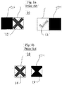
- FIGURE 1a illustrates this particular indicator.
- Each of the MRx, the XL+, and the Heartstream Forerunner AED include a visual indicator 16 for showing the result of the most recent self-test operation, and thus its readiness state while in standby.
- Each of these defibrillators also includes a liquid crystal display (LCD) shutter that is driven shut (opaque) by the self-test system when the most-recent self-test has been successful, as shown by element 19 of FIGURE 1b .
- the opaque shutter obscures an underlying "red- X" graphic 18 to indicate to the user that the AED is ready for use.
- the opaque portion of the LCD shutter is shaped like an hourglass to block the "X" elements of the graphic. When the LCD shutter is de-energized because of either power failure or a "not-ready” determination, the shutter is transparent so that the "red X" graphic 18 is displayed.
- U.S. Pat. No. 5,800,460 "Method for Performing Self-Test in a Defibrillator", issued Sep. 1, 1998 to Powers et al., describes a status indicator for a defibrillator which includes a fail-safe visual display having a multiple-part LCD.
- a top plate of the LCD is a clear window with an "OK" symbol printed on its back.
- a middle plate is an LCD shutter that is biased so as to be opaque when driven by the system monitor via a drive signal.
- a bottom plate has an international “Not” symbol on its top surface.
- the middle plate also includes a separately addressable portion driven by the system monitor via AC-coupled drive.
- the system monitor drives the LCD shutter only when confirmation of successful testing is received within an expected time window, such that only the top plate "OK” is shown against the opaque shutter.
- the shutter is transparent when de-energized as a result of unsuccessful testing or power failure, such that the "OK” appears superimposed over the "Not” symbol to indicate a "Not OK” to the user.
- each of the afore-described references is directed to indicating the readiness status of a defibrillator before it is used in a cardiac arrest rescue.
- each prior readiness indicator is suboptimal, lacking one or more of the following important properties.
- the ready-for-use and not-ready-for-use states must be easily recognizable to all users across all nationalities.
- the "X" shape is easily recognized by all users as a failure indication
- the hourglass shape and "OK" symbol are not easily recognized as a "ready-for-use” indication across all countries and cultures in which the device is used.
- the indicator must be fail-safe, wherein the "not ready” state must be displayed even when no power is available to the device indicator.
- An illuminated readiness indicator such as that using a light emitting diode (LED) does not meet this criterion because the indicator requires power to be seen.
- the readiness indicator must be large enough to be seen from a room-length distance, but must not occupy too much space on the front panel of the medical device.
- a side-by-side visual indicator as described above requires twice as much space on the front panel as an overlaid indicator, reducing the space available for other rescue-related features.
- the readiness indicator should be provide an active indication that the medical device is ready for use, such as by a flashing symbol when appropriate. Therefore, what is needed is a readiness indicator which includes all of these properties.
- an improved visual indicator for indicating the readiness status of a medical device such as a defibrillator is defined in claim 1.
- the visual indicator includes a liquid crystal (LC) shutter which overlays a graphic icon that indicates a not-ready-for use status.
- the LC shutter includes a transparent icon that indicates a ready-for-use status.
- the medical device determines a ready-for-use status, it drives the LC shutter to an opaque state such that the transparent icon is visible and a substantial portion of the graphic icon is obscured.
- a defibrillator which automatically and periodically conducts self-tests to determine its readiness status is defined in claim 12.
- the readiness status is displayed on a visual indicator, similar to that described above, controlled by the device.
- the visual indicator is fail-safe such that a complete loss of power causes the indicator to show a not-ready-for-use status.
- a method for displaying the readiness status of a defibrillator is defined in claim 13.
- the method steps include driving a visual indicator using a control signal from a self-test circuit in order to make visible a transparent icon disposed on an LC shutter.
- the transparent icon indicates that the device is ready-for-use.
- the method may also include a step of cyclically flashing the transparent icon on and off.
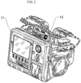
- FIGURE 2 illustrates one embodiment of the invention having a readiness indicator 62, elsewhere referred to as a visual indicator display 62, disposed on the exterior housing of a medical device.
- the exemplary medical device is a defibrillator 22.
- Other medical devices having internal self-testing features, such as patient monitors or ultrasound machines, may also employ the inventive readiness indicator.
- readiness indicator 62 is easily viewable at a distance from the medical device.
- the ready-for-use indication on indicator 62 is a check mark, which is a universally recognized indication that the device is operable.
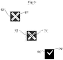
- FIGURE 3 illustrates a more detailed view of the readiness indicator 62 according to a preferred embodiment of the invention.
- This embodiment combines the universally-recognized graphic iconic symbols of an "X" 67 and a check-mark 71 in an overlaid construction.
- the graphic X icon 67 is screen printed or displayed as a background image.
- Overlaying the graphic X icon 67 is an electronic shutter such as a monochromatic liquid crystal (LC) shutter 64. When no power is applied to the LC shutter 64, the LC is transparent and therefore the graphic X icon 67 shows, as seen in the upper left image of FIGURE 3 .
- LC monochromatic liquid crystal
- the LC shutter 64 further includes a transparent icon 70 which overlays a portion of the graphic X icon 67, as shown in the middle image of FIGURE 3 .
- Transparent icon 70 is arranged as a check mark. When power is applied to the LC shutter 64, its portions surrounding the transparent icon 70 check mark are driven opaque. The user thus sees the portions of the graphic X icon 67 through the transparent icon 70 in the shape of a check mark, as seen in the lower right illustration of FIGURE 3 .
- Shading and coloration of the graphic X icon 67 enhances the visibility of the readiness indicator 62 further.
- the inventors have discovered that a white-appearing ready-for-use graphic on the dark (opaque) LC shutter 64 has the desired visibility for the user.
- the colors of the graphic icon are shaded as a light, preferably white, "X" portion surrounded by a darker colored, preferably red, background.
- the not-ready-for-use indication shows red (i.e. hazard)
- the ready-for-use indication shows only the non-alarming lighter shade over which the transparent portion lies.
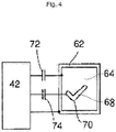
- a defibrillator includes a readiness status circuit 42, which powers a status indicator to indicate the operational status of the defibrillator to a user.
- Readiness status circuit 42 operates in a standby mode to periodically check the hardware components and software components in the device. It also operates continuously when the device is operating.
- the readiness status circuit 42 takes inputs from both self-testing and run-time test components, not shown in FIGURE 4 , to check the operation of the device. If a failure is detected during clinical operations, the readiness status circuit 42 will cause the status indicator to indicate that failure immediately - it does not wait until the next self-test cycle.
- the status indicator comprises a visual indicator display 62 comprising a graphic icon and at least one LC shutter 64.
- the status indicator optionally includes an audible output, such as a piezo buzzer, which beeps, chirps, or issues audible voice alerts when the defibrillator is not ready-for-use.
- visual display 62 comprises a graphic icon, such as the graphic X icon 67 shown in FIGURE 3 , which is selectively obscured by LC shutter 64 turning opaque when driven by the readiness status circuit 42 via control input 72.
- the LC shutter 64 also comprises a portion that is not coupled to drive 72, and which remains transparent. This portion is a transparent icon 70 which has the shape of a check mark or other universally recognizable symbol that the device is ready-for-use.
- the readiness status circuit 42 drives LC shutter 64 only when it has confirmed a successful self-test.
- the visual display 62 would then appear as in FIGURE 5(d) .
- Failure to receive proper test confirmation causes the readiness status circuit 42 to cease issuing drive signals to LC shutter 64 via control input 72.
- LC shutter 64 will then go transparent, thereby exposing the underlying graphic icon 66 to view.
- the visual display 62 would then appear as in FIGURE 5c .
- the readiness status circuit 42 may also then begin powering a piezoelectric failure alert buzzer at that time, preferably for 200 milliseconds, every 10 seconds, so long as there is power enough to do so.
- the primary advantages of the visual display 62 of the preferred embodiment are its low power requirements and the fact that it must be powered to display a ready-for-use indication.
- the low power requirement is especially important in medical devices that are battery-powered, such as an AED.
- the latter advantage ensures the display's fail-safe nature, since the LC shutter 64 cannot be maintained opaque otherwise.
- the transparent icon 70 may be devised as large as necessary for easy viewing, while enjoying a reduced footprint enabled by the overlay design.
- Visual display 62 may also be enabled to separately drive transparent icon 70 into an opaque state.
- the readiness status circuit 42 periodically drives a second LC shutter 68, which is arranged coaxially with both the transparent icon 70 and the graphic icon, via a second LC shutter control input 74.
- Separately addressable transparent icon 70 then also serves as a positive indication (in addition to the fail-safe "check-mark" symbol) that the defibrillator has power and is functioning properly.
- Transparent icon 70 thus appears to flash or blink on and off periodically by means of the alternating driving and releasing of the drive control input 74 signal to second LC shutter 68.
- FIGURE 5a Shown in FIGURE 5a is one embodiment of the construction of readiness indicator 62.
- Graphic icon 66 is printed or formed on a base surface.
- the base surface may be reflective or may be back-lighted.
- One contemplated base surface is reflective and overlaid with a translucent colored plate. A background color is created from incident light passing through the colored plate, which is then reflected back out toward the user.
- Overlying graphic icon 66 is LC shutter 64 having two portions. A driven portion becomes opaque in the presence of control input 72. The drivable portion of LC shutter 64 surrounds a transparent portion comprising a transparent icon 70. A thin layer of glass may overlay the LC shutter 64 for protection.
- FIGURE 5b illustrates an additional embodiment of readiness indicator 62, comprising three coaxial elements.
- the base layer with graphic icon 66 underlies the LC shutter 64 with transparent icon 70.
- a second LC shutter 68 is disposed in the stack, the operation of which obscures transparent icon 70 from the background color of graphic icon 66.
- the second LC shutter 68 is shown underlying LC shutter 64, it is understood that the scope of the invention includes a second LC shutter 68 overlying LC shutter 64, or a second LC shutter 68 that is co-extensive with and co-planar with transparent icon 70.
- FIGURE 5c illustrates the resulting appearance of readiness indicator 62 in the un-driven, not-ready-for-use, state. There, all LC shutters are transparent, and the underlying graphic icon 67 is visible to the user to convey that the device is not operable.
- FIGURE 5d illustrates the resulting appearance of visual readiness indicator 62 in the driven, ready-for-use, state.
- LC shutter 64 is driven opaque, leaving transparent icon 70 viewable as backlit by the light-colored portions of the underlying graphic icon 67.
- the appearance conveys to the user that the device is operable. If the second LC shutter 68 is employed, the transparent icon 70 may appear to flash on and off to convey a further operable status.
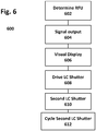
- FIGURE 6 illustrates a method for displaying the operating status of a medical device 600 such as a defibrillator 22, the method employing the visual readiness indicator 62 that has been previously described.
- the method 600 comprises the following steps. First, the defibrillator 22 automatically determines in step 602 by automatic self-testing whether it is ready-for-use. The automatic self-testing can be conducted during either standby or while the device is operating. If the defibrillator is ready-for-use, the defibrillator provides a positive control signal in step 604 from the defibrillator self-test circuit or a related control circuit.
- a visual display is provided that is viewable to a user, and is thus preferably disposed on an external surface of the defibrillator.
- the visual display is similar to that previously described, and includes the graphic icon which indicates a not-ready-for-use status, a LC shutter overlaying the graphic icon.
- the LC shutter includes a transparent visual icon which indicates that the defibrillator is ready for use.
- the positive control signal from the control circuit drives the LC shutter into an opaque state in step 608.
- all but the portion of the graphic icon which underlies the transparent visual icon is obscured by the LC shutter.
- the resulting display appears as a dark background on which is the transparent icon that indicates to the user a ready-to-use status.
- the color of the transparent icon is the unobscured portion of the underlying graphic icon.
- the transparent icon may be back-lit.
- the method may optionally include a step 610 of providing a second LC shutter residing co-axially with the graphic icon and the LC shutter.
- the second LC shutter when driven, obscures the transparent icon portion of the LC shutter.
- the control circuit may drive the second LC shutter off (transparent) and on (opaque), which causes the transparent icon to appear to flash on and off.
- the described readiness indicator 62 has each of the properties that are desired in a more optimal display.
- the ready-for-use and not-ready-for-use states are easily recognizable.
- the use of familiar icons such as an X and a check-mark, in addition to the optional color scheme in the indicator meets is easily recognized by users from all countries as an indication that the device state is ready.
- the indicator is fail-safe.
- the not-ready-for-use state is displayed if power is not available to the device or if internal failure occurs in the device and the indicator is not actively driven to the "ready-for-use" state.
- the readiness indicator 62 is large enough to be seen across a room, while occupying only minimal space on the front panel of the medical device.
- the readiness indicator optionally provides a secondary and active indication that the medical device is ready for use by use of a second LC shutter mechanism which allows the transparent readiness icon 70 to flash, e.g. the invention can periodically black-out the white check mark to create an effect that the check mark is flashing.
- processors When provided by a processor, the functions can be provided by a single dedicated processor, by a single shared processor, or by a plurality of individual processors, some of which can be shared and/or multiplexed.
- explicit use of the term "processor” or “controller” should not be construed to refer exclusively to hardware capable of executing software, and can implicitly include, without limitation, digital signal processor ("DSP") hardware, memory (e.g., read only memory (“ROM”) for storing software, random access memory (“RAM'), non-volatile storage, etc.) and virtually any means and/or machine (including hardware, software, firmware, combinations thereof, etc.) which is capable of (and/or configurable) to perform and/or control a process.
- DSP digital signal processor
- any flow charts, flow diagrams and the like can represent various processes which can be substantially represented in computer readable storage media and so executed by a computer, processor or other device with processing capabilities, whether or not such computer or processor is explicitly shown.
- exemplary embodiments of the present invention can take the form of a computer program product accessible from a computer-usable and/or computer-readable storage medium providing program code and/or instructions for use by or in connection with, e.g., a computer or any instruction execution system.
- a computer-usable or computer readable storage medium can be any apparatus that can, e.g., include, store, communicate, propagate or transport the program for use by or in connection with the instruction execution system, apparatus or device.
- Such exemplary medium can be, e.g., an electronic, magnetic, optical, electromagnetic, infrared or semiconductor system (or apparatus or device) or a propagation medium.
- Examples of a computer-readable medium include, e.g., a semiconductor or solid state memory, magnetic tape, a removable computer diskette, a random access memory (RAM), a read-only memory (ROM), flash (drive), a rigid magnetic disk and an optical disk.
- Current examples of optical disks include compact disk - read only memory (CD-ROM), compact disk - read/write (CD-R/W) and DVD Further, it should be understood that any new computer-readable medium which may hereafter be developed should also be considered as computer-readable medium as may be used or referred to in accordance with exemplary embodiments of the present invention and disclosure.
Landscapes
- Health & Medical Sciences (AREA)
- Engineering & Computer Science (AREA)
- Biomedical Technology (AREA)
- General Health & Medical Sciences (AREA)
- Public Health (AREA)
- Heart & Thoracic Surgery (AREA)
- Nuclear Medicine, Radiotherapy & Molecular Imaging (AREA)
- Veterinary Medicine (AREA)
- Animal Behavior & Ethology (AREA)
- Life Sciences & Earth Sciences (AREA)
- Radiology & Medical Imaging (AREA)
- Cardiology (AREA)
- Human Computer Interaction (AREA)
- Theoretical Computer Science (AREA)
- Business, Economics & Management (AREA)
- General Business, Economics & Management (AREA)
- Quality & Reliability (AREA)
- Physics & Mathematics (AREA)
- General Engineering & Computer Science (AREA)
- General Physics & Mathematics (AREA)
- Epidemiology (AREA)
- Primary Health Care (AREA)
- Medical Informatics (AREA)
- Electrotherapy Devices (AREA)
- Apparatus For Disinfection Or Sterilisation (AREA)
Applications Claiming Priority (2)
| Application Number | Priority Date | Filing Date | Title |
|---|---|---|---|
| US201261745830P | 2012-12-26 | 2012-12-26 | |
| PCT/IB2013/061010 WO2014102658A1 (en) | 2012-12-26 | 2013-12-17 | Intuitive overlaid readiness indicator for defibrillators |
Publications (2)
| Publication Number | Publication Date |
|---|---|
| EP2938398A1 EP2938398A1 (en) | 2015-11-04 |
| EP2938398B1 true EP2938398B1 (en) | 2020-08-12 |
Family
ID=50023807
Family Applications (1)
| Application Number | Title | Priority Date | Filing Date |
|---|---|---|---|
| EP13824524.6A Active EP2938398B1 (en) | 2012-12-26 | 2013-12-17 | Intuitive overlaid readiness indicator for defibrillators |
Country Status (9)
| Country | Link |
|---|---|
| US (1) | US9808639B2 (zh) |
| EP (1) | EP2938398B1 (zh) |
| JP (1) | JP6509125B2 (zh) |
| CN (1) | CN104994907B (zh) |
| BR (1) | BR112015015130A2 (zh) |
| CA (1) | CA2896412A1 (zh) |
| MX (1) | MX358817B (zh) |
| RU (1) | RU2661023C2 (zh) |
| WO (1) | WO2014102658A1 (zh) |
Families Citing this family (5)
| Publication number | Priority date | Publication date | Assignee | Title |
|---|---|---|---|---|
| WO2014102658A1 (en) | 2012-12-26 | 2014-07-03 | Koninklijke Philips N.V. | Intuitive overlaid readiness indicator for defibrillators |
| EP3240608B1 (en) * | 2014-12-30 | 2019-11-20 | Koninklijke Philips N.V. | Advanced warning indicator for emergency medical devices |
| GB201721767D0 (en) * | 2017-12-22 | 2018-02-07 | Heartsine Tech Limited | Defibrillator status indication and activation |
| JP7486353B2 (ja) * | 2020-06-05 | 2024-05-17 | 日本光電工業株式会社 | 自動体外式除細動器、及び自動体外式除細動器の異常報知方法 |
| JP7418289B2 (ja) * | 2020-06-05 | 2024-01-19 | 日本光電工業株式会社 | 自動体外式除細動器、及び自動体外式除細動器の状態表示方法 |
Family Cites Families (22)
| Publication number | Priority date | Publication date | Assignee | Title |
|---|---|---|---|---|
| US4562433A (en) * | 1980-09-02 | 1985-12-31 | Mcdonnell Douglas Corporation | Fail transparent LCD display |
| JPH01237794A (ja) * | 1988-03-18 | 1989-09-22 | Hitachi Ltd | 自動機の取扱表示器 |
| JPH04343326A (ja) * | 1991-05-20 | 1992-11-30 | Nikon Corp | 液晶表示装置 |
| US5879374A (en) | 1993-05-18 | 1999-03-09 | Heartstream, Inc. | External defibrillator with automatic self-testing prior to use |
| ATE381953T1 (de) * | 1993-05-18 | 2008-01-15 | Koninkl Philips Electronics Nv | Defibrillator mit einem selbst-test-system |
| US5797969A (en) | 1995-08-01 | 1998-08-25 | Survivalink Corporation | One button lid activated automatic external defibrillator |
| CN1184929C (zh) * | 1995-12-27 | 2005-01-19 | 希森美康株式会社 | 非侵入式血液分析仪 |
| WO2000051520A2 (en) * | 1999-03-02 | 2000-09-08 | Kems Bio-Test Ltd. | Bovine pregnancy testing |
| US6871093B2 (en) * | 2000-12-28 | 2005-03-22 | Koninklijke Philips Electronics N.V. | Reporting the status for an external defibrillator with an audible report in response to a specified user input |
| US20040164166A1 (en) | 2002-07-18 | 2004-08-26 | Intermec Ip Corp. | Indicator for communicating system status information |
| US7623915B2 (en) * | 2003-07-16 | 2009-11-24 | Medtronic Physio-Control Corp. | Interactive first aid information system |
| EP3289974B1 (de) * | 2003-09-03 | 2019-10-23 | ResMed R&D Germany GmbH | Erfassungsgerät zur observation schlafbezogener atmungsstörungen |
| RU2278420C1 (ru) * | 2005-02-03 | 2006-06-20 | Валерий Георгиевич Бубнов | Робот-тренажер |
| US20080177341A1 (en) | 2006-10-27 | 2008-07-24 | Bowers Kyle R | Automated external defibrillator (AED) system with multiple patient wireless monitoring capability for use in mass casualty incidents |
| US9486286B2 (en) * | 2007-05-14 | 2016-11-08 | Boston Scientific Scimed, Inc. | Medical laser user interface |
| EP3453418A1 (en) * | 2007-07-06 | 2019-03-13 | Manta Devices, LLC | Delivery device and related methods |
| PL2440287T3 (pl) * | 2009-06-09 | 2013-12-31 | Bredent Medical Gmbh & Co Kg | Urządzenie do terapii fotodynamicznej |
| EP2506926B1 (en) | 2009-11-30 | 2016-08-03 | Zoll Medical Corporation | Display for dual-mode medical device |
| JP6090776B2 (ja) * | 2010-02-12 | 2017-03-08 | ゾール メディカル コーポレイションZOLL Medical Corporation | 除細動器のディスプレイ |
| US20120123491A1 (en) * | 2010-11-15 | 2012-05-17 | William Tom Hunter | Defibrillator device with status indicating transport handle |
| WO2012071545A1 (en) * | 2010-11-24 | 2012-05-31 | New Productivity Group, Llc | Detection and feedback of information associated with executive function |
| WO2014102658A1 (en) | 2012-12-26 | 2014-07-03 | Koninklijke Philips N.V. | Intuitive overlaid readiness indicator for defibrillators |
-
2013
- 2013-12-17 WO PCT/IB2013/061010 patent/WO2014102658A1/en active Application Filing
- 2013-12-17 CA CA2896412A patent/CA2896412A1/en not_active Abandoned
- 2013-12-17 BR BR112015015130A patent/BR112015015130A2/pt not_active Application Discontinuation
- 2013-12-17 MX MX2015008213A patent/MX358817B/es active IP Right Grant
- 2013-12-17 JP JP2015550173A patent/JP6509125B2/ja active Active
- 2013-12-17 CN CN201380068659.4A patent/CN104994907B/zh active Active
- 2013-12-17 RU RU2015130912A patent/RU2661023C2/ru active
- 2013-12-17 EP EP13824524.6A patent/EP2938398B1/en active Active
- 2013-12-17 US US14/655,974 patent/US9808639B2/en active Active
Non-Patent Citations (1)
| Title |
|---|
| None * |
Also Published As
| Publication number | Publication date |
|---|---|
| RU2015130912A (ru) | 2017-01-31 |
| JP2016501659A (ja) | 2016-01-21 |
| MX358817B (es) | 2018-09-05 |
| BR112015015130A2 (pt) | 2017-07-11 |
| CN104994907B (zh) | 2017-07-18 |
| EP2938398A1 (en) | 2015-11-04 |
| US9808639B2 (en) | 2017-11-07 |
| CA2896412A1 (en) | 2014-07-03 |
| US20150335902A1 (en) | 2015-11-26 |
| MX2015008213A (es) | 2015-09-29 |
| RU2661023C2 (ru) | 2018-07-11 |
| JP6509125B2 (ja) | 2019-05-08 |
| WO2014102658A1 (en) | 2014-07-03 |
| CN104994907A (zh) | 2015-10-21 |
Similar Documents
| Publication | Publication Date | Title |
|---|---|---|
| EP2938398B1 (en) | Intuitive overlaid readiness indicator for defibrillators | |
| US20220409913A1 (en) | Display for dual-mode medical device | |
| Fairbanks et al. | Poor interface design and lack of usability testing facilitate medical error | |
| US20090054939A1 (en) | Automated External Defibrillator (AED) With Context-Sensitive Help | |
| JP2011240162A (ja) | 介護者の処置の進行に基づく注意喚起を行う自動介護装置 | |
| CN101500646A (zh) | 用于对多种心律失常情况进行分析的体外除颤器 | |
| RU2633472C2 (ru) | Прижимные электроды дефибриллятора с подсвечиваемыми кнопками разряда | |
| JP6118346B2 (ja) | 自動体外式除細動器のための2言語コントローラ | |
| JP2016501659A5 (zh) | ||
| US20120123491A1 (en) | Defibrillator device with status indicating transport handle | |
| US9403026B2 (en) | Language placard for an automated external defibrillator | |
| KR200475681Y1 (ko) | 자동 제세동기 | |
| EP4161632B1 (en) | Automated external defibrillator and method for displaying state of automated external defibrillator | |
| KR102211140B1 (ko) | 장애인 겸용 자동 제세동기 | |
| CN111543976B (zh) | 除颤器装置 | |
| CN114515383A (zh) | 除颤设备、终端设备的控制方法、除颤设备和存储介质 |
Legal Events
| Date | Code | Title | Description |
|---|---|---|---|
| PUAI | Public reference made under article 153(3) epc to a published international application that has entered the european phase |
Free format text: ORIGINAL CODE: 0009012 |
|
| 17P | Request for examination filed |
Effective date: 20150727 |
|
| AK | Designated contracting states |
Kind code of ref document: A1 Designated state(s): AL AT BE BG CH CY CZ DE DK EE ES FI FR GB GR HR HU IE IS IT LI LT LU LV MC MK MT NL NO PL PT RO RS SE SI SK SM TR |
|
| AX | Request for extension of the european patent |
Extension state: BA ME |
|
| DAX | Request for extension of the european patent (deleted) | ||
| GRAP | Despatch of communication of intention to grant a patent |
Free format text: ORIGINAL CODE: EPIDOSNIGR1 |
|
| STAA | Information on the status of an ep patent application or granted ep patent |
Free format text: STATUS: GRANT OF PATENT IS INTENDED |
|
| RIC1 | Information provided on ipc code assigned before grant |
Ipc: A61N 1/372 20060101ALI20191022BHEP Ipc: A61N 1/39 20060101AFI20191022BHEP Ipc: G16H 40/40 20180101ALI20191022BHEP |
|
| INTG | Intention to grant announced |
Effective date: 20191119 |
|
| RAP1 | Party data changed (applicant data changed or rights of an application transferred) |
Owner name: KONINKLIJKE PHILIPS N.V. |
|
| GRAJ | Information related to disapproval of communication of intention to grant by the applicant or resumption of examination proceedings by the epo deleted |
Free format text: ORIGINAL CODE: EPIDOSDIGR1 |
|
| STAA | Information on the status of an ep patent application or granted ep patent |
Free format text: STATUS: REQUEST FOR EXAMINATION WAS MADE |
|
| GRAP | Despatch of communication of intention to grant a patent |
Free format text: ORIGINAL CODE: EPIDOSNIGR1 |
|
| STAA | Information on the status of an ep patent application or granted ep patent |
Free format text: STATUS: GRANT OF PATENT IS INTENDED |
|
| INTC | Intention to grant announced (deleted) | ||
| INTG | Intention to grant announced |
Effective date: 20200415 |
|
| RIN1 | Information on inventor provided before grant (corrected) |
Inventor name: DELISLE, NORMAN MAURICE |
|
| GRAS | Grant fee paid |
Free format text: ORIGINAL CODE: EPIDOSNIGR3 |
|
| GRAA | (expected) grant |
Free format text: ORIGINAL CODE: 0009210 |
|
| STAA | Information on the status of an ep patent application or granted ep patent |
Free format text: STATUS: THE PATENT HAS BEEN GRANTED |
|
| AK | Designated contracting states |
Kind code of ref document: B1 Designated state(s): AL AT BE BG CH CY CZ DE DK EE ES FI FR GB GR HR HU IE IS IT LI LT LU LV MC MK MT NL NO PL PT RO RS SE SI SK SM TR |
|
| REG | Reference to a national code |
Ref country code: CH Ref legal event code: EP |
|
| REG | Reference to a national code |
Ref country code: IE Ref legal event code: FG4D |
|
| REG | Reference to a national code |
Ref country code: DE Ref legal event code: R096 Ref document number: 602013071619 Country of ref document: DE |
|
| REG | Reference to a national code |
Ref country code: AT Ref legal event code: REF Ref document number: 1300934 Country of ref document: AT Kind code of ref document: T Effective date: 20200915 |
|
| REG | Reference to a national code |
Ref country code: NL Ref legal event code: FP |
|
| REG | Reference to a national code |
Ref country code: LT Ref legal event code: MG4D |
|
| PG25 | Lapsed in a contracting state [announced via postgrant information from national office to epo] |
Ref country code: HR Free format text: LAPSE BECAUSE OF FAILURE TO SUBMIT A TRANSLATION OF THE DESCRIPTION OR TO PAY THE FEE WITHIN THE PRESCRIBED TIME-LIMIT Effective date: 20200812 Ref country code: FI Free format text: LAPSE BECAUSE OF FAILURE TO SUBMIT A TRANSLATION OF THE DESCRIPTION OR TO PAY THE FEE WITHIN THE PRESCRIBED TIME-LIMIT Effective date: 20200812 Ref country code: NO Free format text: LAPSE BECAUSE OF FAILURE TO SUBMIT A TRANSLATION OF THE DESCRIPTION OR TO PAY THE FEE WITHIN THE PRESCRIBED TIME-LIMIT Effective date: 20201112 Ref country code: ES Free format text: LAPSE BECAUSE OF FAILURE TO SUBMIT A TRANSLATION OF THE DESCRIPTION OR TO PAY THE FEE WITHIN THE PRESCRIBED TIME-LIMIT Effective date: 20200812 Ref country code: LT Free format text: LAPSE BECAUSE OF FAILURE TO SUBMIT A TRANSLATION OF THE DESCRIPTION OR TO PAY THE FEE WITHIN THE PRESCRIBED TIME-LIMIT Effective date: 20200812 Ref country code: GR Free format text: LAPSE BECAUSE OF FAILURE TO SUBMIT A TRANSLATION OF THE DESCRIPTION OR TO PAY THE FEE WITHIN THE PRESCRIBED TIME-LIMIT Effective date: 20201113 Ref country code: SE Free format text: LAPSE BECAUSE OF FAILURE TO SUBMIT A TRANSLATION OF THE DESCRIPTION OR TO PAY THE FEE WITHIN THE PRESCRIBED TIME-LIMIT Effective date: 20200812 Ref country code: BG Free format text: LAPSE BECAUSE OF FAILURE TO SUBMIT A TRANSLATION OF THE DESCRIPTION OR TO PAY THE FEE WITHIN THE PRESCRIBED TIME-LIMIT Effective date: 20201112 |
|
| REG | Reference to a national code |
Ref country code: AT Ref legal event code: MK05 Ref document number: 1300934 Country of ref document: AT Kind code of ref document: T Effective date: 20200812 |
|
| PG25 | Lapsed in a contracting state [announced via postgrant information from national office to epo] |
Ref country code: IS Free format text: LAPSE BECAUSE OF FAILURE TO SUBMIT A TRANSLATION OF THE DESCRIPTION OR TO PAY THE FEE WITHIN THE PRESCRIBED TIME-LIMIT Effective date: 20201212 Ref country code: LV Free format text: LAPSE BECAUSE OF FAILURE TO SUBMIT A TRANSLATION OF THE DESCRIPTION OR TO PAY THE FEE WITHIN THE PRESCRIBED TIME-LIMIT Effective date: 20200812 Ref country code: PL Free format text: LAPSE BECAUSE OF FAILURE TO SUBMIT A TRANSLATION OF THE DESCRIPTION OR TO PAY THE FEE WITHIN THE PRESCRIBED TIME-LIMIT Effective date: 20200812 Ref country code: RS Free format text: LAPSE BECAUSE OF FAILURE TO SUBMIT A TRANSLATION OF THE DESCRIPTION OR TO PAY THE FEE WITHIN THE PRESCRIBED TIME-LIMIT Effective date: 20200812 |
|
| PG25 | Lapsed in a contracting state [announced via postgrant information from national office to epo] |
Ref country code: RO Free format text: LAPSE BECAUSE OF FAILURE TO SUBMIT A TRANSLATION OF THE DESCRIPTION OR TO PAY THE FEE WITHIN THE PRESCRIBED TIME-LIMIT Effective date: 20200812 Ref country code: SM Free format text: LAPSE BECAUSE OF FAILURE TO SUBMIT A TRANSLATION OF THE DESCRIPTION OR TO PAY THE FEE WITHIN THE PRESCRIBED TIME-LIMIT Effective date: 20200812 Ref country code: CZ Free format text: LAPSE BECAUSE OF FAILURE TO SUBMIT A TRANSLATION OF THE DESCRIPTION OR TO PAY THE FEE WITHIN THE PRESCRIBED TIME-LIMIT Effective date: 20200812 Ref country code: EE Free format text: LAPSE BECAUSE OF FAILURE TO SUBMIT A TRANSLATION OF THE DESCRIPTION OR TO PAY THE FEE WITHIN THE PRESCRIBED TIME-LIMIT Effective date: 20200812 Ref country code: DK Free format text: LAPSE BECAUSE OF FAILURE TO SUBMIT A TRANSLATION OF THE DESCRIPTION OR TO PAY THE FEE WITHIN THE PRESCRIBED TIME-LIMIT Effective date: 20200812 |
|
| REG | Reference to a national code |
Ref country code: DE Ref legal event code: R097 Ref document number: 602013071619 Country of ref document: DE |
|
| PG25 | Lapsed in a contracting state [announced via postgrant information from national office to epo] |
Ref country code: AT Free format text: LAPSE BECAUSE OF FAILURE TO SUBMIT A TRANSLATION OF THE DESCRIPTION OR TO PAY THE FEE WITHIN THE PRESCRIBED TIME-LIMIT Effective date: 20200812 Ref country code: AL Free format text: LAPSE BECAUSE OF FAILURE TO SUBMIT A TRANSLATION OF THE DESCRIPTION OR TO PAY THE FEE WITHIN THE PRESCRIBED TIME-LIMIT Effective date: 20200812 |
|
| PLBE | No opposition filed within time limit |
Free format text: ORIGINAL CODE: 0009261 |
|
| STAA | Information on the status of an ep patent application or granted ep patent |
Free format text: STATUS: NO OPPOSITION FILED WITHIN TIME LIMIT |
|
| PG25 | Lapsed in a contracting state [announced via postgrant information from national office to epo] |
Ref country code: SK Free format text: LAPSE BECAUSE OF FAILURE TO SUBMIT A TRANSLATION OF THE DESCRIPTION OR TO PAY THE FEE WITHIN THE PRESCRIBED TIME-LIMIT Effective date: 20200812 |
|
| 26N | No opposition filed |
Effective date: 20210514 |
|
| PG25 | Lapsed in a contracting state [announced via postgrant information from national office to epo] |
Ref country code: IT Free format text: LAPSE BECAUSE OF FAILURE TO SUBMIT A TRANSLATION OF THE DESCRIPTION OR TO PAY THE FEE WITHIN THE PRESCRIBED TIME-LIMIT Effective date: 20200812 |
|
| REG | Reference to a national code |
Ref country code: CH Ref legal event code: PL |
|
| PG25 | Lapsed in a contracting state [announced via postgrant information from national office to epo] |
Ref country code: SI Free format text: LAPSE BECAUSE OF FAILURE TO SUBMIT A TRANSLATION OF THE DESCRIPTION OR TO PAY THE FEE WITHIN THE PRESCRIBED TIME-LIMIT Effective date: 20200812 Ref country code: MC Free format text: LAPSE BECAUSE OF FAILURE TO SUBMIT A TRANSLATION OF THE DESCRIPTION OR TO PAY THE FEE WITHIN THE PRESCRIBED TIME-LIMIT Effective date: 20200812 |
|
| REG | Reference to a national code |
Ref country code: BE Ref legal event code: MM Effective date: 20201231 |
|
| PG25 | Lapsed in a contracting state [announced via postgrant information from national office to epo] |
Ref country code: LU Free format text: LAPSE BECAUSE OF NON-PAYMENT OF DUE FEES Effective date: 20201217 Ref country code: IE Free format text: LAPSE BECAUSE OF NON-PAYMENT OF DUE FEES Effective date: 20201217 |
|
| PG25 | Lapsed in a contracting state [announced via postgrant information from national office to epo] |
Ref country code: LI Free format text: LAPSE BECAUSE OF NON-PAYMENT OF DUE FEES Effective date: 20201231 Ref country code: CH Free format text: LAPSE BECAUSE OF NON-PAYMENT OF DUE FEES Effective date: 20201231 |
|
| PG25 | Lapsed in a contracting state [announced via postgrant information from national office to epo] |
Ref country code: TR Free format text: LAPSE BECAUSE OF FAILURE TO SUBMIT A TRANSLATION OF THE DESCRIPTION OR TO PAY THE FEE WITHIN THE PRESCRIBED TIME-LIMIT Effective date: 20200812 Ref country code: MT Free format text: LAPSE BECAUSE OF FAILURE TO SUBMIT A TRANSLATION OF THE DESCRIPTION OR TO PAY THE FEE WITHIN THE PRESCRIBED TIME-LIMIT Effective date: 20200812 Ref country code: CY Free format text: LAPSE BECAUSE OF FAILURE TO SUBMIT A TRANSLATION OF THE DESCRIPTION OR TO PAY THE FEE WITHIN THE PRESCRIBED TIME-LIMIT Effective date: 20200812 |
|
| PG25 | Lapsed in a contracting state [announced via postgrant information from national office to epo] |
Ref country code: MK Free format text: LAPSE BECAUSE OF FAILURE TO SUBMIT A TRANSLATION OF THE DESCRIPTION OR TO PAY THE FEE WITHIN THE PRESCRIBED TIME-LIMIT Effective date: 20200812 |
|
| PG25 | Lapsed in a contracting state [announced via postgrant information from national office to epo] |
Ref country code: PT Free format text: LAPSE BECAUSE OF FAILURE TO SUBMIT A TRANSLATION OF THE DESCRIPTION OR TO PAY THE FEE WITHIN THE PRESCRIBED TIME-LIMIT Effective date: 20200812 Ref country code: BE Free format text: LAPSE BECAUSE OF NON-PAYMENT OF DUE FEES Effective date: 20201231 |
|
| PGFP | Annual fee paid to national office [announced via postgrant information from national office to epo] |
Ref country code: GB Payment date: 20231219 Year of fee payment: 11 |
|
| PGFP | Annual fee paid to national office [announced via postgrant information from national office to epo] |
Ref country code: NL Payment date: 20231226 Year of fee payment: 11 Ref country code: FR Payment date: 20231226 Year of fee payment: 11 |
|
| PGFP | Annual fee paid to national office [announced via postgrant information from national office to epo] |
Ref country code: DE Payment date: 20231227 Year of fee payment: 11 |