EP2937191A1 - Cutting machine for elongated-shaped food articles - Google Patents
Cutting machine for elongated-shaped food articles Download PDFInfo
- Publication number
- EP2937191A1 EP2937191A1 EP15001078.3A EP15001078A EP2937191A1 EP 2937191 A1 EP2937191 A1 EP 2937191A1 EP 15001078 A EP15001078 A EP 15001078A EP 2937191 A1 EP2937191 A1 EP 2937191A1
- Authority
- EP
- European Patent Office
- Prior art keywords
- cutting machine
- shaft
- area
- bottom element
- machine according
- Prior art date
- Legal status (The legal status is an assumption and is not a legal conclusion. Google has not performed a legal analysis and makes no representation as to the accuracy of the status listed.)
- Granted
Links
- 238000005520 cutting process Methods 0.000 title claims abstract description 68
- 235000013305 food Nutrition 0.000 title claims abstract description 26
- 238000004140 cleaning Methods 0.000 claims description 16
- JEIPFZHSYJVQDO-UHFFFAOYSA-N iron(III) oxide Inorganic materials O=[Fe]O[Fe]=O JEIPFZHSYJVQDO-UHFFFAOYSA-N 0.000 claims description 2
- 230000032258 transport Effects 0.000 description 10
- 244000007853 Sarothamnus scoparius Species 0.000 description 4
- 235000008429 bread Nutrition 0.000 description 3
- 230000007246 mechanism Effects 0.000 description 3
- 238000004806 packaging method and process Methods 0.000 description 3
- 230000007257 malfunction Effects 0.000 description 2
- 230000000007 visual effect Effects 0.000 description 2
- 208000027418 Wounds and injury Diseases 0.000 description 1
- 238000009825 accumulation Methods 0.000 description 1
- 230000002411 adverse Effects 0.000 description 1
- 230000015572 biosynthetic process Effects 0.000 description 1
- 235000013351 cheese Nutrition 0.000 description 1
- 210000000078 claw Anatomy 0.000 description 1
- 230000006378 damage Effects 0.000 description 1
- 238000011161 development Methods 0.000 description 1
- 230000018109 developmental process Effects 0.000 description 1
- 230000006872 improvement Effects 0.000 description 1
- 208000014674 injury Diseases 0.000 description 1
- 238000003780 insertion Methods 0.000 description 1
- 230000037431 insertion Effects 0.000 description 1
- 238000012423 maintenance Methods 0.000 description 1
- 238000000034 method Methods 0.000 description 1
- 230000008569 process Effects 0.000 description 1
- 230000008439 repair process Effects 0.000 description 1
- 238000009420 retrofitting Methods 0.000 description 1
- 125000006850 spacer group Chemical group 0.000 description 1
- 238000012546 transfer Methods 0.000 description 1
Images

Classifications
-
- B—PERFORMING OPERATIONS; TRANSPORTING
- B26—HAND CUTTING TOOLS; CUTTING; SEVERING
- B26D—CUTTING; DETAILS COMMON TO MACHINES FOR PERFORATING, PUNCHING, CUTTING-OUT, STAMPING-OUT OR SEVERING
- B26D7/00—Details of apparatus for cutting, cutting-out, stamping-out, punching, perforating, or severing by means other than cutting
- B26D7/18—Means for removing cut-out material or waste
-
- B—PERFORMING OPERATIONS; TRANSPORTING
- B26—HAND CUTTING TOOLS; CUTTING; SEVERING
- B26D—CUTTING; DETAILS COMMON TO MACHINES FOR PERFORATING, PUNCHING, CUTTING-OUT, STAMPING-OUT OR SEVERING
- B26D1/00—Cutting through work characterised by the nature or movement of the cutting member or particular materials not otherwise provided for; Apparatus or machines therefor; Cutting members therefor
- B26D1/01—Cutting through work characterised by the nature or movement of the cutting member or particular materials not otherwise provided for; Apparatus or machines therefor; Cutting members therefor involving a cutting member which does not travel with the work
- B26D1/12—Cutting through work characterised by the nature or movement of the cutting member or particular materials not otherwise provided for; Apparatus or machines therefor; Cutting members therefor involving a cutting member which does not travel with the work having a cutting member moving about an axis
- B26D1/14—Cutting through work characterised by the nature or movement of the cutting member or particular materials not otherwise provided for; Apparatus or machines therefor; Cutting members therefor involving a cutting member which does not travel with the work having a cutting member moving about an axis with a circular cutting member, e.g. disc cutter
- B26D1/157—Cutting through work characterised by the nature or movement of the cutting member or particular materials not otherwise provided for; Apparatus or machines therefor; Cutting members therefor involving a cutting member which does not travel with the work having a cutting member moving about an axis with a circular cutting member, e.g. disc cutter rotating about a movable axis
- B26D1/16—Cutting through work characterised by the nature or movement of the cutting member or particular materials not otherwise provided for; Apparatus or machines therefor; Cutting members therefor involving a cutting member which does not travel with the work having a cutting member moving about an axis with a circular cutting member, e.g. disc cutter rotating about a movable axis mounted on a movable arm or the like
-
- B—PERFORMING OPERATIONS; TRANSPORTING
- B26—HAND CUTTING TOOLS; CUTTING; SEVERING
- B26D—CUTTING; DETAILS COMMON TO MACHINES FOR PERFORATING, PUNCHING, CUTTING-OUT, STAMPING-OUT OR SEVERING
- B26D7/00—Details of apparatus for cutting, cutting-out, stamping-out, punching, perforating, or severing by means other than cutting
- B26D2007/0012—Details, accessories or auxiliary or special operations not otherwise provided for
- B26D2007/0018—Trays, reservoirs for waste, chips or cut products
-
- B—PERFORMING OPERATIONS; TRANSPORTING
- B26—HAND CUTTING TOOLS; CUTTING; SEVERING
- B26D—CUTTING; DETAILS COMMON TO MACHINES FOR PERFORATING, PUNCHING, CUTTING-OUT, STAMPING-OUT OR SEVERING
- B26D2210/00—Machines or methods used for cutting special materials
- B26D2210/02—Machines or methods used for cutting special materials for cutting food products, e.g. food slicers
- B26D2210/06—Machines or methods used for cutting special materials for cutting food products, e.g. food slicers for bread, e.g. bread slicing machines for use in a retail store
Definitions
- the invention relates to a cutting machine with which can be cut into arbitrarily thick slices of bread, cheese and the like string-shaped food.
- the cutting machine according to the invention may in particular be a circular knife machine.
- a round knife machine for cutting a sliced strand of food known.
- This cutting machine has a circular cutting blade, which rotate about its central axis and can also be swung around in a circular path. In this pivoting movement, it is passed through the sliced food to be cut in slices.
- the rope-shaped food is supplied to the cutting blade in a channel-like shaft and cut into slices.
- the cut slices are stored standing on a downstream of the cutting blade in the conveying direction bearing surface.
- the storage area for the cut slices and the storage area for the not yet sliced food strand lie in a plane that is oriented obliquely in space.
- the bearing means for the cut slices may vibrate. As a result, each cut slice can be easily detached from the cutting blade and does not adhere to the same.
- the present invention seeks to provide an improved cutting machine that allows trouble-free operation and conveys a visually appealing impression even after frequent use.
- the cutting machine has at least one cutting knife for the rope-shaped food and a shaft for receiving the rope-shaped food.
- the feed direction of the strand-shaped food corresponds to the longitudinal direction of the shaft.
- the shaft has a first shaft area in front of the cutting blade and a second shaft area after the cutting blade, which are at least partially separated from each other by a slot. In this slot, the cutting blade can rotate during the cutting process.
- at least one bottom element is present, which above the first and / or the second shaft area is present.
- the bottom element has at least one breakthrough.
- the bottom element is present at a small distance from the shaft area and visually acts as the bottom of the loading area or the removal area.
- the resulting crumbs can fall onto the shaft area present below the floor element.
- the crumbs are thus no longer visible, which leads to a visually appealing impression, without the cutting machine must be cleaned several times a day.
- the crumbs can no longer complicate the return of the transport gripper in its starting position, so that malfunction can be minimized.
- an additional floor element By using an additional floor element, the existing manhole can be maintained, so that the mechanics and electronics of the cutting machine remain protected by this existing manhole.
- An additional floor element above the existing shaft also allows easy retrofitting of existing cutting machines, since the basic dimensions of the cutting machine need not be changed.
- the floor element can have one or more spacers in the form of webs or pins in its lateral edge area.
- the bottom element may have a plurality of slots or holes as openings, so that the crumbs can fall through the bottom element as unhindered as possible.
- the bottom element could therefore also be designed as a grate.
- the bottom element can in particular be detachably fastened to the shaft area.
- the releasable attachment can prevent the operators from unauthorizedly removing the bottom element, and on the other hand, the floor element can still be removed from the shaft area in such a way that cleaning of the shaft area is possible.
- the bottom element can in particular be hingedly attached to the shaft area.
- the floor element can in this case preferably be folded away to the rear, so that the shaft area is freely accessible.
- the bottom element may be formed in two parts. In this way, one part of the bottom element may be stationary, while the other part of the bottom element may be designed to be movable.
- the transport gripper for the inserted food must be placed above the floor element. In order nevertheless to allow easy cleaning of the shaft area below the floor element, the transport gripper can be moved during the cleaning on the stationary front part of the floor element in the region of the slot between the two shaft areas. Subsequently, the movable part of the floor element can be pivoted or folded so that the underlying shaft area is freely accessible and can be cleaned. In order to be able to repair or service the cutting machine, the stationary part of the floor element can additionally be removed from the shaft area.
- the distance between the shaft area and the floor element may be greater at the one end of the shaft area than at the opposite end of the shaft area.
- the distance between the shaft area and the floor element in the region of the slot-side end of the shaft area can be greater than at the end-side end of the shaft area.
- the shaft area can be inclined in the direction of the slot. In this way, the crumbs passing through the floor element on the manhole area fall, slide in the direction of the slot and be collected there in a crumb tray.
- the distance between the manhole area and the floor element in the region of the end-side end of the manhole area may be greater than at the slot-side end of the manhole area.
- another crumb tray could be arranged in the edge region of the cutting machine into which the crumbs could slip.
- the inclination of the shaft area could also run in the direction of the front, user-side end of the cutting machine. In this way, the manhole area remain largely free of crumbs, so that even in the formation of the bottom element as rust or with a plurality of openings a visually appealing image remains.
- a cleaning element may, for example, be a vibrating element, as already used for releasing the cut slices from the circular blade. Such a vibrating element could cause the bottom element and also the shaft area below it to oscillate. Alternatively or additionally, a broom element or another wiping element, for example in the form of a wiper lip, could be present. It would also be possible to provide at least one cleaning nozzle, so that the crumbs are blown in particular in the direction of the slot by means of a blast of compressed air. In addition, at least one suction element could be provided, by means of which the crumbs can be sucked. Cleaning nozzle or suction element could be formed both stationary and movable.
- the floor element according to the invention could be arranged both in the loading area and in the removal area of the cutting machine.
- that part of the shaft of the cutting machine, under which the mechanics of the cutting machine should be arranged is to be equipped with a closed shaft floor to adequately shield the mechanics.
- the floor element according to the invention therefore offers particular.
- the shaft floor itself could already be equipped with corresponding openings so that the crumbs accumulating there fall into the cutting machine and could collect there, for example, in a crumb tray.
- the cutting machine 10 is formed in the present example case as a circular knife machine with a circular blade, not shown.
- the circular blade is mounted in a conventional manner on a swing arm, which is moved by a motor drive.
- the motor drive also allows rotation of the circular blade.
- the cutting machine 10 is designed for the self-service area and has a housing 12 which can be closed at the top by a flap 14. As long as the flap 14 is opened, the circular blade is blocked in order to prevent a risk of injury from the circular blade.
- the housing 12 has in the left in the drawing area a door 16 which can be opened for cleaning and maintenance purposes. Behind this door 16 is also a crumb tray, in which the costs incurred in the operation of the cutting machine 10 crumbs are collected.
- the cutting machine 10 has a shaft 20 whose longitudinal direction corresponds to the feed direction of an inserted strand-shaped food.
- the shaft 20 of the cutting machine 10 has a first, right shaft portion 22 and a second, left shaft portion 24, which are separated by a slot 26.
- Driven by the knife drive moves the circular blade through this slot 26 so that the present in the region of the slot 26 food is cut at this point.
- Based on the drawing then arises to the left of this slot 26 a food slice.
- the insert area for the food to be cut in the region of the right shaft area 22 and the removal area for the disk package is in the area of the second, left shaft area 24.
- a transport gripper 28 For cutting the food strand is pushed by a transport gripper 28 in the direction of the slot 26.
- the transport gripper 28 has a plurality of adjacent claws that pierce the cutting process from above into the end of the food.
- a disc support 30 is arranged behind the slot 26 .
- the disk support 30 is pivotably mounted on an axis so that subsequent disks can move the disk support 30 accordingly.
- a packaging aid 32 is provided in the region of the removal region, onto which the slice package can be placed. Subsequently, for example, a bag or bag may be slipped over the disc package and the packaging aid to transfer the disc package into the bag or bag.
- the bottom element 40 is formed in one piece in the present example and has a plurality of openings in the form of slots 42. Through these slots 42, the resulting crumbs through the bottom member 40 can pass through the right shaft area 22. The crumbs are thus out of sight and therefore can not adversely affect the visual impression of the cutting machine 10.
- the insert area of the cutting machine 10 therefore looks clean and thus visually appealing even after several cutting operations.
- the floor element 40 can be removed from the loading area of the cutting machine by lifting it.
- the right shaft area 22 is thus freely accessible and can be cleaned, for example, with a broom.
- the mechanism of the cutting machine 10 is arranged below the loading area of the cutting machine 10. To this mechanics too protect the shaft area 22 is equipped with a continuous shaft bottom.
- the shaft bottom of the shaft region 24 of the removal region can have a plurality of apertures 50 in the form of slots, so that a further base element can be dispensed with in this region.
- the shaft area 24 of the removal area can be equipped with a corresponding floor element. In this case, could be dispensed with a bottom element in the loading area of the cutting machine.
- the right manhole area 22 is not oriented horizontally but rather inclined in the direction of the slot 26.
- the bottom element 40 is aligned horizontally so that the distance of the bottom element 40 and the shaft region 22 in the region of the slot 26 is greater than in the region of the transport gripper 28 (see FIG Fig. 5 ).
- the inclination 60 of the shaft area 22 is about 2.4 degrees. This inclination 60 is sufficient for the crumbs that land on the shaft area 22 to slip in the direction of the slot 26 and fall there into a crumb tray (not shown). In this way, even on the shaft area no large amount of crumbs accumulate.
- this embodiment leads to a further visual improvement of the overall impression of the cutting machine.
- the cleaning of the shaft area 22 could still be supported by additional cleaning element, for example a vibration device or a broom element.
- additional cleaning element for example a vibration device or a broom element.
- a vibration device or a broom element could be attached to the transport gripper, a broom element or a wiper lip, which also transported in the direction of the slot, the existing crumbs in the direction of the slot in the process of transporting the gripper.
- a cleaning element could then be moved to a second position, in which it does not come to a touch of the crumbs to prevent remaining crumbs are moved into the end region of the manhole area.
- the bottom element could also be formed in two parts and have a stationary and a movable part.
- the two parts could be fastened to each other by means of one or more hinges, so that the movable part of the floor element could be folded upwards.
- the transport gripper could be positioned above the stationary part in order to be able to fold the movable part of the floor element upwards and clean the shaft area underneath.
Landscapes
- Life Sciences & Earth Sciences (AREA)
- Forests & Forestry (AREA)
- Engineering & Computer Science (AREA)
- Mechanical Engineering (AREA)
- Cleaning In General (AREA)
Abstract
Eine erfindungsgemäße Schneidmaschine 10 für strangförmige Lebensmittel besitzt ein Schneidmesser für das strangförmige Lebensmittel und einen Schacht 20 zur Aufnahme des strangförmigen Lebensmittels. Die Längsrichtung des Schachtes 20 entspricht der Vorschubrichtung des strangförmigen Lebensmittels. Der Schacht 20 besitzt einen ersten Schachtbereich und einen zweiten Schachtbereich 24, die durch einen Schlitz 26 zumindest teilweise voneinander getrennt sind. Erfindungsgemäß ist zumindest ein Bodenelement 40 vorhanden, das oberhalb des ersten und/oder des zweiten Schachtbereichs angeordnet ist und das zumindest einen Durchbruch 42 aufweist.A string-shaped food cutting machine 10 according to the invention has a cutting knife for the rope-shaped food and a shaft 20 for receiving the string-shaped food. The longitudinal direction of the shaft 20 corresponds to the feed direction of the strand-shaped food. The shaft 20 has a first shaft region and a second shaft region 24 which are at least partially separated from one another by a slot 26. According to the invention, at least one bottom element 40 is present, which is arranged above the first and / or the second shaft area and which has at least one opening 42.
Description
Die Erfindung betrifft eine Schneidmaschine, mit der sich Brot, Käse und dergleichen strangförmige Lebensmittel maschinell in beliebig dicke Scheiben schneiden lassen. Bei der erfindungsgemäßen Schneidmaschine kann es sich insbesondere um eine Rundmessermaschine handeln.The invention relates to a cutting machine with which can be cut into arbitrarily thick slices of bread, cheese and the like string-shaped food. The cutting machine according to the invention may in particular be a circular knife machine.
Aus der
Entsprechend der
Beim Schneiden eines Laibes Brot entstehen in der Regel einige Krümel, die sich über die Zeit im Einlege- und Entnahmebereich sammeln. Diese Krümel vermitteln ein unaufgeräumtes Bild, so dass ein negativer Gesamteindruck der Schneidmaschine entstehen kann. Dies gilt insbesondere dann, wenn die Schneidmaschine im Selbstbedienungsbereich aufgestellt ist, so dass die Schneidmaschine direkt von den Kunden bedient wird. Darüber hinaus kann es bei einer Ansammlung einer größeren Menge Krümel im Einlegebereich der Schneidmaschine zu einer Fehlfunktion der Schneidmaschine kommen, da der Greifer, der das unzerschnittene Brot in Richtung der Schneideinrichtung transportiert, nicht mehr bis in seine Ausgangsposition zurückfahren kann, weil die Krümel diese Position blockieren.When slicing a loaf of bread, there are usually a few crumbs that accumulate over time in the loading and unloading area. These crumbs give a tidy picture, so that a negative overall impression of the cutting machine can arise. This is especially true when the cutting machine is placed in the self-service area, so that the cutting machine is operated directly by the customer. Moreover, accumulation of a larger amount of crumbs in the loading area of the cutting machine may cause the cutting machine to malfunction, as the gripper which transports the uncooked bread towards the cutter can not return to its original position because the crumbs are in that position To block.
Ausgehend von diesem vorbekannten Stand der Technik liegt der Erfindung die Aufgabe zugrunde, eine verbesserte Schneidmaschine anzugeben, die einen störungsfreien Betrieb ermöglicht und auch nach häufigem Gebrauch einen optisch ansprechenden Eindruck vermittelt.Based on this known prior art, the present invention seeks to provide an improved cutting machine that allows trouble-free operation and conveys a visually appealing impression even after frequent use.
Die erfindungsgemäße Schneidmaschine ist durch die Merkmale des Hauptanspruchs 1 gegeben. Sinnvolle Weiterbildungen der Erfindung sind Gegenstand von sich an den Hauptanspruch anschließenden weiteren Ansprüchen.The cutting machine according to the invention is given by the features of the main claim 1. Useful developments of the invention are the subject of further claims appending to the main claim.
Die erfindungsgemäße Schneidmaschine besitzt zumindest ein Schneidmesser für das strangförmige Lebensmittel und einen Schacht zur Aufnahme des strangförmigen Lebensmittels. Die Vorschubrichtung des strangförmigen Lebensmittels entspricht der Längsrichtung des Schachts. Der Schacht weist einen ersten Schachtbereich vor dem Schneidmesser und einen zweiten Schachtbereich nach dem Schneidmesser auf, die durch einen Schlitz zumindest teilweise voneinander getrennt sind. In diesem Schlitz kann das Schneidmesser während des Schneidvorgangs rotieren. Erfindungsgemäß ist zumindest ein Bodenelement vorhanden, das oberhalb des ersten und/oder des zweiten Schachtbereichs vorhanden ist. Das Bodenelement besitzt dabei zumindest einen Durchbruch.The cutting machine according to the invention has at least one cutting knife for the rope-shaped food and a shaft for receiving the rope-shaped food. The feed direction of the strand-shaped food corresponds to the longitudinal direction of the shaft. The shaft has a first shaft area in front of the cutting blade and a second shaft area after the cutting blade, which are at least partially separated from each other by a slot. In this slot, the cutting blade can rotate during the cutting process. According to the invention, at least one bottom element is present, which above the first and / or the second shaft area is present. The bottom element has at least one breakthrough.
Das Bodenelement ist dabei mit einem geringen Abstand zu dem Schachtbereich vorhanden und wirkt optisch als Boden des Einlegebereichs oder des Entnahmebereichs. Durch den Durchbruch innerhalb des Bodenelements können die anfallenden Krümel auf den unterhalb des Bodenelements vorhandenen Schachtbereich fallen. Die Krümel sind somit nicht mehr sichtbar, was zu einem optisch ansprechenderen Eindruck führt, ohne dass die Schneidmaschine mehrmals täglich gereinigt werden muss. Darüber hinaus können die Krümel auch nicht mehr das Zurückfahren des Transportgreifers in dessen Ausgangsposition erschweren, so dass Fehlfunktionen minimiert werden können.The bottom element is present at a small distance from the shaft area and visually acts as the bottom of the loading area or the removal area. As a result of the breakthrough within the floor element, the resulting crumbs can fall onto the shaft area present below the floor element. The crumbs are thus no longer visible, which leads to a visually appealing impression, without the cutting machine must be cleaned several times a day. In addition, the crumbs can no longer complicate the return of the transport gripper in its starting position, so that malfunction can be minimized.
Durch die Verwendung eines zusätzlichen Bodenelements kann darüber hinaus der bestehende Schacht erhalten bleiben, so dass die Mechanik und Elektronik der Schneidmaschine durch diesen bestehenden Schacht geschützt bleibt. Ein zusätzliches Bodenelement oberhalb des bestehenden Schachtes ermöglicht darüber hinaus ein einfaches Nachrüsten bereits bestehender Schneidmaschinen, da die grundlegenden Abmessungen der Schneidmaschine nicht verändert werden müssen.In addition, by using an additional floor element, the existing manhole can be maintained, so that the mechanics and electronics of the cutting machine remain protected by this existing manhole. An additional floor element above the existing shaft also allows easy retrofitting of existing cutting machines, since the basic dimensions of the cutting machine need not be changed.
Um den Abstand zwischen Bodenelement und Schachtbereich aufrecht zu erhalten, kann das Bodenelement in seinem seitlichen Randbereich jeweils einen oder mehrere Abstandshalter in Form von Stegen oder Stiften aufweisen.In order to maintain the distance between the floor element and the shaft area, the floor element can have one or more spacers in the form of webs or pins in its lateral edge area.
Vorzugsweise kann das Bodenelement mehrere Schlitze oder Löcher als Durchbrüche aufweisen, so dass die Krümel möglichst ungehindert durch das Bodenelement hindurchfallen können. Das Bodenelement könnte daher auch als Rost ausgebildet sein.Preferably, the bottom element may have a plurality of slots or holes as openings, so that the crumbs can fall through the bottom element as unhindered as possible. The bottom element could therefore also be designed as a grate.
Das Bodenelement kann insbesondere lösbar an dem Schachtbereich befestigt sein. Die lösbare Befestigung kann einerseits verhindern, dass die Bediener unbefugt das Bodenelement entnehmen, andererseits kann das Bodenelement nach wie vor so aus dem Schachtbereich entfernt werden, dass eine Reinigung des Schachtbereichs möglich ist. Dazu kann das Bodenelement insbesondere klappbar an dem Schachtbereich befestigt sein. Zur Reinigung des Schachtbereiches kann das Bodenelement in diesem Fall vorzugsweise nach hinten weggeklappt werden, so dass der Schachtbereich frei zugänglich ist.The bottom element can in particular be detachably fastened to the shaft area. On the one hand, the releasable attachment can prevent the operators from unauthorizedly removing the bottom element, and on the other hand, the floor element can still be removed from the shaft area in such a way that cleaning of the shaft area is possible. For this purpose, the bottom element can in particular be hingedly attached to the shaft area. In order to clean the shaft area, the floor element can in this case preferably be folded away to the rear, so that the shaft area is freely accessible.
In einer besonders bevorzugten Ausführungsform kann das Bodenelement zweiteilig ausgebildet sein. Auf diese Weise kann das eine Teil des Bodenelements stationär ausgebildet sein, während das andere Teil des Bodenelements beweglich ausgebildet sein kann. Der Transportgreifer für das eingelegte Lebensmittel muss oberhalb des Bodenelements platziert werden. Um dennoch eine einfache Reinigung des Schachtbereichs unterhalb des Bodenelements zu ermöglichen, kann der Transportgreifer während der Reinigung auf den stationären vorderen Teil des Bodenelements in den Bereich des Schlitzes zwischen den beiden Schachtbereichen verfahren werden. Anschließend kann der bewegliche Teil des Bodenelements so verschwenkt oder geklappt werden, dass der darunter liegende Schachtbereich frei zugänglich ist und gereinigt werden kann. Um die Schneidmaschine reparieren oder warten zu können, kann zusätzlich auch der stationäre Teil des Bodenelements aus dem Schachtbereich entnommen werden.In a particularly preferred embodiment, the bottom element may be formed in two parts. In this way, one part of the bottom element may be stationary, while the other part of the bottom element may be designed to be movable. The transport gripper for the inserted food must be placed above the floor element. In order nevertheless to allow easy cleaning of the shaft area below the floor element, the transport gripper can be moved during the cleaning on the stationary front part of the floor element in the region of the slot between the two shaft areas. Subsequently, the movable part of the floor element can be pivoted or folded so that the underlying shaft area is freely accessible and can be cleaned. In order to be able to repair or service the cutting machine, the stationary part of the floor element can additionally be removed from the shaft area.
In einer besonders vorteilhaften Ausführungsform kann der Abstand zwischen dem Schachtbereich und dem Bodenelement an dem einen Ende des Schachtbereichs größer sein als an dem gegenüber liegenden Ende des Schachtbereichs. Insbesondere kann der Abstand zwischen dem Schachtbereich und dem Bodenelement im Bereich des schlitzseitigen Endes des Schachtbereichs größer sein als an dem endseitigen Ende des Schachtbereichs. Dadurch kann der Schachtbereich in Richtung des Schlitzes geneigt ausgebildet sein. Auf diese Weise können die Krümel, die durch das Bodenelement auf den Schachtbereich fallen, in Richtung des Schlitzes rutschen und dort in einer Krümelwanne gesammelt werden. Alternativ dazu kann der Abstand zwischen dem Schachtbereich und dem Bodenelement im Bereich des endseitigen Endes des Schachtbereichs größer sein als an dem schlitzseitigen Ende des Schachtbereichs. In diesem Fall könnte eine weitere Krümelwanne im Randbereich der Schneidmaschine angeordnet sein, in die die Krümel hineinrutschen könnten. Die Neigung des Schachtbereichs könnte auch in Richtung des vorderen, bedienseitigen Endes der Schneidmaschine verlaufen. Auf diese Weise kann auch der Schachtbereich weitgehend krümelfrei bleiben, so dass auch bei der Ausbildung des Bodenelements als Rost oder mit einer Vielzahl von Durchbrüchen ein optisch ansprechendes Bild bestehen bleibt.In a particularly advantageous embodiment, the distance between the shaft area and the floor element may be greater at the one end of the shaft area than at the opposite end of the shaft area. In particular, the distance between the shaft area and the floor element in the region of the slot-side end of the shaft area can be greater than at the end-side end of the shaft area. As a result, the shaft area can be inclined in the direction of the slot. In this way, the crumbs passing through the floor element on the manhole area fall, slide in the direction of the slot and be collected there in a crumb tray. Alternatively, the distance between the manhole area and the floor element in the region of the end-side end of the manhole area may be greater than at the slot-side end of the manhole area. In this case, another crumb tray could be arranged in the edge region of the cutting machine into which the crumbs could slip. The inclination of the shaft area could also run in the direction of the front, user-side end of the cutting machine. In this way, the manhole area remain largely free of crumbs, so that even in the formation of the bottom element as rust or with a plurality of openings a visually appealing image remains.
Die Reinigung des Bodenelements und des darunter liegenden Schachtbereichs könnte dadurch noch erleichtert werden, dass ein zusätzliches Reinigungselement für das Bodenelement und/oder den darunter liegenden Schachtbereich vorhanden ist. Bei einem solchen Reinigungselement kann es sich beispielsweise um ein Vibrationselement handeln, wie es bereits zum Lösen der geschnittenen Scheiben von dem Kreismesser verwendet wird. Ein solches Vibrationselement könnte das Bodenelement und auch der darunter liegende Schachtbereich in Schwingungen versetzt werden. Alternativ oder zusätzlich dazu könnte ein Besenelement oder ein sonstiges Wischelement, beispielsweise in Form einer Wischlippe, vorhanden sein. Es wäre auch möglich, zumindest eine Reinigungsdüse vorzusehen, so dass die Krümel insbesondere mittels eines Druckluftstoßes in Richtung des Schlitzes geblasen werden. Darüber hinaus könnte auch zumindest ein Saugelement vorgesehen werden, mittels dem die Krümel eingesaugt werden können. Reinigungsdüse oder Saugelement könnten dabei sowohl stationär als auch beweglich ausgebildet sein.The cleaning of the floor element and the shaft area underneath could still be facilitated by the fact that an additional cleaning element for the floor element and / or the underlying shaft area is present. Such a cleaning element may, for example, be a vibrating element, as already used for releasing the cut slices from the circular blade. Such a vibrating element could cause the bottom element and also the shaft area below it to oscillate. Alternatively or additionally, a broom element or another wiping element, for example in the form of a wiper lip, could be present. It would also be possible to provide at least one cleaning nozzle, so that the crumbs are blown in particular in the direction of the slot by means of a blast of compressed air. In addition, at least one suction element could be provided, by means of which the crumbs can be sucked. Cleaning nozzle or suction element could be formed both stationary and movable.
Das erfindungsgemäße Bodenelement könnte sowohl im Einlegebereich als auch im Entnahmebereich der Schneidmaschine angeordnet werden. In der Regel sollte derjenige Teil des Schachtes der Schneidmaschine, unter dem die Mechanik der Schneidmaschine angeordnet ist, mit einem geschlossenen Schachtboden ausgestattet sein, um die Mechanik ausreichend abzuschirmen. In diesem Bereich bietet sich das erfindungsgemäße Bodenelement daher besonders an. Bei demjenigen Bereich des Schachtes, unter dem keine Mechanik angeordnet ist, könnte dagegen der Schachtboden selbst bereits mit entsprechenden Durchbrüchen ausgestattet sein, so dass die dort anfallenden Krümel in die Schneidmaschine hineinfallen und sich dort beispielsweise in einer Krümelwanne sammeln könnten.The floor element according to the invention could be arranged both in the loading area and in the removal area of the cutting machine. As a rule, that part of the shaft of the cutting machine, under which the mechanics of the cutting machine should be arranged is to be equipped with a closed shaft floor to adequately shield the mechanics. In this area, the floor element according to the invention therefore offers particular. In the area of the shaft, under which no mechanism is arranged, however, the shaft floor itself could already be equipped with corresponding openings so that the crumbs accumulating there fall into the cutting machine and could collect there, for example, in a crumb tray.
Weitere Vorteile und Merkmale der Erfindung sind den in den Ansprüchen ferner angegebenen Merkmalen sowie dem nachstehenden Ausführungsbeispiel zu entnehmen.Further advantages and features of the invention are given in the claims further specified features and the following embodiment.
Die Erfindung wird im Folgenden anhand des in der Zeichnung dargestellten Ausführungsbeispiels näher beschrieben und erläutert. Es zeigen:
- Fig. 1
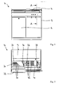
- die Frontansicht einer erfindungsgemäßen Schneidmaschine,
- Fig. 2
- die Draufsicht auf die erfindungsgemäße Schneidmaschine gemäß
Fig. 1 , - Fig. 3
- einen Querschnitt durch die erfindungsgemäße Schneidmaschine gemäß
Fig. 1 entlang der Linie A-A, - Fig. 4
- einen Detailausschnitt X des Querschnitts gemäß
Fig. 3 und - Fig. 5
- einen Längsschnitt durch die erfindungsgemäße Schneidmaschine entlang der Linie B-B entsprechend
Fig. 3 .
- Fig. 1
- the front view of a cutting machine according to the invention,
- Fig. 2
- the top view of the cutting machine according to the invention according to
Fig. 1 . - Fig. 3
- a cross section through the cutting machine according to the invention according to
Fig. 1 along the line AA, - Fig. 4
- a detail X of the cross section according to
Fig. 3 and - Fig. 5
- a longitudinal section through the cutting machine according to the invention along the line BB accordingly
Fig. 3 ,
Die erfindungsgemäße Schneidmaschine 10 ist im vorliegenden Beispielsfall als Rundmessermaschine mit einem nicht näher dargestellten Kreismesser ausgebildet. Das Kreismesser ist in üblicher Art und Weise an einem Schwingarm gelagert, welcher durch einen motorischen Antrieb bewegt wird. Durch den motorischen Antrieb ist auch eine Rotation des Kreismessers möglich.The cutting
Die Schneidmaschine 10 ist für den Selbstbedienungsbereich ausgelegt und besitzt ein Gehäuse 12, das im oberen Bereich durch eine Klappe 14 geschlossen werden kann. Solange die Klappe 14 geöffnet ist, ist das Kreismesser blockiert, um eine Verletzungsgefahr durch das Kreismesser zu verhindern. Das Gehäuse 12 besitzt in dem in der Zeichnung linken Bereich eine Tür 16, die zu Reinigungs- und Wartungszwecken geöffnet werden kann. Hinter dieser Tür 16 befindet sich auch eine Krümelwanne, in der die beim Betrieb der Schneidmaschine 10 anfallenden Krümel gesammelt werden.The cutting
Die Schneidmaschine 10 besitzt einen Schacht 20, dessen Längsrichtung der Vorschubrichtung eines eingelegten strangförmigen Lebensmittels entspricht. Der Schacht 20 der Schneidmaschine 10 besitzt einen ersten, rechten Schachtbereich 22 und einen zweiten, linken Schachtbereich 24, die durch einen Schlitz 26 voneinander getrennt sind. Durch den Messerantrieb angetrieben wandert das Kreismesser durch diesen Schlitz 26, so dass das im Bereich des Schlitzes 26 vorhandene Lebensmittel an dieser Stelle zertrennt wird. Bezogen auf die Zeichnung entsteht dann links von diesem Schlitz 26 eine Lebensmittelscheibe. Rechts des Schlitzes 26 ist das Lebensmittel noch unzertrennt vorhanden. Daher befindet sich der Einlegebereich für das zu schneidende Lebensmittel im Bereich des rechten Schachtbereichs 22 und der Entnahmebereich für das Scheiben-Paket im Bereich des zweiten, linken Schachtbereichs 24.The cutting
Zum Zerschneiden wird der Lebensmittel-Strang durch einen Transportgreifer 28 in Richtung auf den Schlitz 26 geschoben. Dazu besitzt der Transportgreifer 28 mehrere nebeneinander liegende Krallen, die beim Schneidvorgang von oben in das Ende des Lebensmittels hineinstechen. Um ein Umfallen der geschnittenen Scheiben des Lebensmittel-Stranges zu verhindern, ist hinter dem Schlitz 26 eine Scheibenstütze 30 angeordnet. Die Scheibenstütze 30 ist an einer Achse verschwenkbar gelagert, so dass nachfolgende Scheiben die Scheibenstütze 30 entsprechend verschieben können. Um die Verpackung des geschnittenen Scheiben-Pakets zu erleichtern, ist im Bereich des Entnahmebereichs eine Verpackungshilfe 32 vorhanden, auf die das Scheiben-Paket aufgelegt werden kann. Anschließend kann beispielsweise eine Tüte oder ein Beutel über das Scheiben-Paket und die Verpackungshilfe gestülpt werden, um das Scheiben-Paket in die Tüte oder den Beutel zu überführen.For cutting the food strand is pushed by a
Im Einlegebereich der Schneidmaschine 10 befindet sich ein erstes Bodenelement 40. Das Bodenelement 40 ist im vorliegenden Beispielsfall einteilig ausgebildet und weist eine Vielzahl von Durchbrüchen in Form von Schlitzen 42 auf. Durch diese Schlitze 42 können die anfallenden Krümel durch das Bodenelement 40 hindurch auf den rechten Schachtbereich 22 fallen. Die Krümel sind somit außer Sichtweite und können daher den optischen Eindruck der Schneidmaschine 10 nicht negativ beeinträchtigen. Der Einlegebereich der Schneidmaschine 10 sieht daher auch nach mehreren Schneidvorgängen sauber und damit optisch ansprechend aus.In the insertion region of the cutting
Um den rechten Schachtbereich 22 reinigen zu können, kann das Bodenelement 40 aus dem Einlegebereich der Schneidmaschine entfernt werden, indem dieses angehoben wird. Der rechte Schachtbereich 22 ist somit frei zugänglich und kann beispielsweise mit einem Besen gereinigt werden.In order to be able to clean the
Unterhalb des Einlegebereichs der Schneidmaschine 10 ist die Mechanik der Schneidmaschine 10 angeordnet. Um diese Mechanik zu schützen, ist der Schachtbereich 22 mit einem durchgehenden Schachtboden ausgestattet. Demgegenüber kann der Schachtboden des Schachtbereiches 24 des Entnahmebereichs mehrere Durchbrüche 50 in Form von Schlitzen aufweisen, so dass in diesem Bereich auf ein weiteres Bodenelement verzichtet werden kann. Sofern die Mechanik unterhalb des Entnahmebereichs angeordnet ist, kann der Schachtbereich 24 des Entnahmebereichs mit einem entsprechenden Bodenelement ausgestattet werden. In diesem Fall könnte auf ein Bodenelement im Einlegebereich der Schneidmaschine verzichtet werden.Below the loading area of the cutting
Bei dem vorliegenden Beispielsfall ist der rechte Schachtbereich 22 nicht horizontal ausgerichtet, sondern vielmehr in Richtung des Schlitzes 26 geneigt. Das Bodenelement 40 ist dagegen horizontal ausgerichtet, so dass der Abstand des Bodenelements 40 und dem Schachtbereich 22 im Bereich des Schlitzes 26 größer ist als im Bereich des Transportgreifers 28 (siehe
Die Reinigung des Schachtbereichs 22 könnte durch zusätzliche Reinigungselement, beispielsweise eine Vibrationseinrichtung oder ein Besenelement noch unterstützt werden. Beispielsweise könnte an dem Transportgreifer ein Besenelement oder eine Wischlippe befestigt sein, die beim Verfahren des Transportgreifers in Richtung des Schlitzes die vorhandenen Krümel ebenfalls in Richtung des Schlitzes befördert. Beim Zurückfahren des Transportgreifers könnte eine solches Reinigungselement dann in eine zweite Position verfahren werden, bei dem es nicht zu einer Berührung der Krümel kommt, um zu verhindern, dass verbleibende Krümel in den endseitigen Bereich des Schachtbereichs verschoben werden.The cleaning of the
Im Gegensatz zu dem in der Zeichnung dargestellten Beispielsfall könnte das Bodenelement auch zweiteilig ausgebildet sein und ein stationäres und eine bewegliches Teil besitzen. Die beiden Teile könnten mittels einem oder mehrerer Scharniere aneinander befestigt sein, so dass der bewegliche Teil des Bodenelements nach oben geklappt werden könnte. Der Transportgreifer könnte in diesem Fall oberhalb des stationären Teils positioniert werden, um den beweglichen Teil der Bodenelements noch oben klappen und den darunter befindlichen Schachtbereich reinigen zu können.In contrast to the example case shown in the drawing, the bottom element could also be formed in two parts and have a stationary and a movable part. The two parts could be fastened to each other by means of one or more hinges, so that the movable part of the floor element could be folded upwards. In this case, the transport gripper could be positioned above the stationary part in order to be able to fold the movable part of the floor element upwards and clean the shaft area underneath.
Im Gegensatz zu dem in der Zeichnung dargestellten Ausführungsbeispiel könnte es sich bei der erfindungsgemäßen Schneidmaschine auch um eine Gatterschneidmaschine handeln.In contrast to the embodiment shown in the drawing, it could also be a gate cutting machine in the cutting machine according to the invention.
Claims (10)
Applications Claiming Priority (1)
| Application Number | Priority Date | Filing Date | Title |
|---|---|---|---|
| DE102014005813.1A DE102014005813A1 (en) | 2014-04-24 | 2014-04-24 | Cutting machine for rope-shaped food |
Publications (2)
| Publication Number | Publication Date |
|---|---|
| EP2937191A1 true EP2937191A1 (en) | 2015-10-28 |
| EP2937191B1 EP2937191B1 (en) | 2016-11-02 |
Family
ID=52875395
Family Applications (1)
| Application Number | Title | Priority Date | Filing Date |
|---|---|---|---|
| EP15001078.3A Active EP2937191B1 (en) | 2014-04-24 | 2015-04-15 | Cutting machine for elongated-shaped food articles |
Country Status (2)
| Country | Link |
|---|---|
| EP (1) | EP2937191B1 (en) |
| DE (1) | DE102014005813A1 (en) |
Cited By (1)
| Publication number | Priority date | Publication date | Assignee | Title |
|---|---|---|---|---|
| EP3831558A1 (en) * | 2019-12-05 | 2021-06-09 | Bizerba SE & Co. KG | Bread cutting machine with cutting process aid and preferential operating method |
Citations (5)
| Publication number | Priority date | Publication date | Assignee | Title |
|---|---|---|---|---|
| DE19820004C2 (en) | 1998-05-06 | 2000-06-08 | Uwe Reifenhaeuser | Machine for cutting a strand of material into slices |
| EP2045053A2 (en) | 2007-10-01 | 2009-04-08 | SILLER, Rudi | Disc cutting machine for elongated-shape food |
| DE102010036721A1 (en) * | 2010-07-29 | 2012-02-02 | Uwe Reifenhäuser | Method for cutting loaf of bread by bread cutting machine, involves packing bread slices by pushing through opening in wall of receiving region closed by closure device, to prevent manual intervention |
| DE202013009201U1 (en) * | 2013-10-18 | 2014-02-04 | CUT Verwaltung UG (haftungsbeschränkt) | Slicer for bread |
| EP2886269A1 (en) * | 2013-12-18 | 2015-06-24 | SILLER, Rudi | Cutting machine for string-shaped food |
Family Cites Families (1)
| Publication number | Priority date | Publication date | Assignee | Title |
|---|---|---|---|---|
| DE102012100589A1 (en) * | 2012-01-24 | 2013-07-25 | R. Weiss Verpackungstechnik Gmbh & Co. Kg | Bread slicer with cleaning device |
-
2014
- 2014-04-24 DE DE102014005813.1A patent/DE102014005813A1/en not_active Withdrawn
-
2015
- 2015-04-15 EP EP15001078.3A patent/EP2937191B1/en active Active
Patent Citations (5)
| Publication number | Priority date | Publication date | Assignee | Title |
|---|---|---|---|---|
| DE19820004C2 (en) | 1998-05-06 | 2000-06-08 | Uwe Reifenhaeuser | Machine for cutting a strand of material into slices |
| EP2045053A2 (en) | 2007-10-01 | 2009-04-08 | SILLER, Rudi | Disc cutting machine for elongated-shape food |
| DE102010036721A1 (en) * | 2010-07-29 | 2012-02-02 | Uwe Reifenhäuser | Method for cutting loaf of bread by bread cutting machine, involves packing bread slices by pushing through opening in wall of receiving region closed by closure device, to prevent manual intervention |
| DE202013009201U1 (en) * | 2013-10-18 | 2014-02-04 | CUT Verwaltung UG (haftungsbeschränkt) | Slicer for bread |
| EP2886269A1 (en) * | 2013-12-18 | 2015-06-24 | SILLER, Rudi | Cutting machine for string-shaped food |
Cited By (2)
| Publication number | Priority date | Publication date | Assignee | Title |
|---|---|---|---|---|
| EP3831558A1 (en) * | 2019-12-05 | 2021-06-09 | Bizerba SE & Co. KG | Bread cutting machine with cutting process aid and preferential operating method |
| WO2021110361A1 (en) * | 2019-12-05 | 2021-06-10 | Bizerba SE & Co. KG | Bread cutting machine with cutting process aid, and preferred operating method |
Also Published As
| Publication number | Publication date |
|---|---|
| EP2937191B1 (en) | 2016-11-02 |
| DE102014005813A1 (en) | 2015-10-29 |
Similar Documents
| Publication | Publication Date | Title |
|---|---|---|
| EP2886269B1 (en) | Cutting machine for string-shaped food | |
| DE202008003603U1 (en) | Slicing machine for rope shaped food | |
| EP3102376B1 (en) | Sclicing method and slicing machine for foodstuffs in block form | |
| EP2796252B1 (en) | Slicing machine for strand-shaped food | |
| DE102005019949B4 (en) | Method and device for cutting food, in particular for cutting bread in bread slicing machines | |
| EP2937191B1 (en) | Cutting machine for elongated-shaped food articles | |
| DE102012007311B4 (en) | Food slicing and dividing device, in particular for cutting or dividing bread | |
| DE102016010635B4 (en) | Cutting machine for rope-shaped food | |
| DE102012100587A1 (en) | Cutting device for bread | |
| DE102017109196A1 (en) | Slicing machine with detachable docking tray | |
| DE102006060862B4 (en) | harvester | |
| DE102018003556A1 (en) | Cutting machine for rope-shaped food | |
| AT9436U1 (en) | MACHINE FRAME FOR A BREAD CUTTING MACHINE | |
| DE102014011167B4 (en) | Cutting machine for string-shaped food | |
| DE102012100589A1 (en) | Bread slicer with cleaning device | |
| DE2627301A1 (en) | Machine for cutting meat cubes - has slotted plate and cutting roller with several blade discs engaging in slots | |
| DE102009052857A1 (en) | cutting machine | |
| DE102019006614B4 (en) | Cutting machine for string-shaped food | |
| DE102006060863B4 (en) | harvester | |
| DE202016001529U1 (en) | Cutting machine for rope-shaped food | |
| DE19840261C2 (en) | Device for cutting material to be cut | |
| WO2021110367A1 (en) | Bread cutting machine with integrated bagging aid, and preferred operating method | |
| DE102013010531A1 (en) | Collection and discharge device for cutting residues in circular-slicer cutting machines | |
| EP1136200B1 (en) | Machine for cutting strips of foodstuff or for dicing | |
| DE894335C (en) | Haeckselmaschine |
Legal Events
| Date | Code | Title | Description |
|---|---|---|---|
| PUAI | Public reference made under article 153(3) epc to a published international application that has entered the european phase |
Free format text: ORIGINAL CODE: 0009012 |
|
| AK | Designated contracting states |
Kind code of ref document: A1 Designated state(s): AL AT BE BG CH CY CZ DE DK EE ES FI FR GB GR HR HU IE IS IT LI LT LU LV MC MK MT NL NO PL PT RO RS SE SI SK SM TR |
|
| AX | Request for extension of the european patent |
Extension state: BA ME |
|
| RAP1 | Party data changed (applicant data changed or rights of an application transferred) |
Owner name: MHS SCHNEIDETECHNIK GMBH |
|
| 17P | Request for examination filed |
Effective date: 20160224 |
|
| RBV | Designated contracting states (corrected) |
Designated state(s): AL AT BE BG CH CY CZ DE DK EE ES FI FR GB GR HR HU IE IS IT LI LT LU LV MC MK MT NL NO PL PT RO RS SE SI SK SM TR |
|
| GRAP | Despatch of communication of intention to grant a patent |
Free format text: ORIGINAL CODE: EPIDOSNIGR1 |
|
| RIC1 | Information provided on ipc code assigned before grant |
Ipc: B26D 7/00 20060101ALN20160504BHEP Ipc: B26D 1/16 20060101ALN20160504BHEP Ipc: B26D 7/18 20060101AFI20160504BHEP |
|
| RIC1 | Information provided on ipc code assigned before grant |
Ipc: B26D 1/16 20060101ALN20160517BHEP Ipc: B26D 7/18 20060101AFI20160517BHEP Ipc: B26D 7/00 20060101ALN20160517BHEP |
|
| INTG | Intention to grant announced |
Effective date: 20160601 |
|
| GRAS | Grant fee paid |
Free format text: ORIGINAL CODE: EPIDOSNIGR3 |
|
| GRAA | (expected) grant |
Free format text: ORIGINAL CODE: 0009210 |
|
| AK | Designated contracting states |
Kind code of ref document: B1 Designated state(s): AL AT BE BG CH CY CZ DE DK EE ES FI FR GB GR HR HU IE IS IT LI LT LU LV MC MK MT NL NO PL PT RO RS SE SI SK SM TR |
|
| REG | Reference to a national code |
Ref country code: GB Ref legal event code: FG4D Free format text: NOT ENGLISH |
|
| REG | Reference to a national code |
Ref country code: AT Ref legal event code: REF Ref document number: 841361 Country of ref document: AT Kind code of ref document: T Effective date: 20161115 Ref country code: CH Ref legal event code: EP |
|
| REG | Reference to a national code |
Ref country code: IE Ref legal event code: FG4D Free format text: LANGUAGE OF EP DOCUMENT: GERMAN |
|
| REG | Reference to a national code |
Ref country code: DE Ref legal event code: R096 Ref document number: 502015000266 Country of ref document: DE |
|
| PG25 | Lapsed in a contracting state [announced via postgrant information from national office to epo] |
Ref country code: LV Free format text: LAPSE BECAUSE OF FAILURE TO SUBMIT A TRANSLATION OF THE DESCRIPTION OR TO PAY THE FEE WITHIN THE PRESCRIBED TIME-LIMIT Effective date: 20161102 |
|
| REG | Reference to a national code |
Ref country code: NL Ref legal event code: MP Effective date: 20161102 |
|
| REG | Reference to a national code |
Ref country code: LT Ref legal event code: MG4D |
|
| PG25 | Lapsed in a contracting state [announced via postgrant information from national office to epo] |
Ref country code: NL Free format text: LAPSE BECAUSE OF FAILURE TO SUBMIT A TRANSLATION OF THE DESCRIPTION OR TO PAY THE FEE WITHIN THE PRESCRIBED TIME-LIMIT Effective date: 20161102 Ref country code: LT Free format text: LAPSE BECAUSE OF FAILURE TO SUBMIT A TRANSLATION OF THE DESCRIPTION OR TO PAY THE FEE WITHIN THE PRESCRIBED TIME-LIMIT Effective date: 20161102 Ref country code: NO Free format text: LAPSE BECAUSE OF FAILURE TO SUBMIT A TRANSLATION OF THE DESCRIPTION OR TO PAY THE FEE WITHIN THE PRESCRIBED TIME-LIMIT Effective date: 20170202 Ref country code: SE Free format text: LAPSE BECAUSE OF FAILURE TO SUBMIT A TRANSLATION OF THE DESCRIPTION OR TO PAY THE FEE WITHIN THE PRESCRIBED TIME-LIMIT Effective date: 20161102 |
|
| PG25 | Lapsed in a contracting state [announced via postgrant information from national office to epo] |
Ref country code: HR Free format text: LAPSE BECAUSE OF FAILURE TO SUBMIT A TRANSLATION OF THE DESCRIPTION OR TO PAY THE FEE WITHIN THE PRESCRIBED TIME-LIMIT Effective date: 20161102 Ref country code: RS Free format text: LAPSE BECAUSE OF FAILURE TO SUBMIT A TRANSLATION OF THE DESCRIPTION OR TO PAY THE FEE WITHIN THE PRESCRIBED TIME-LIMIT Effective date: 20161102 Ref country code: FI Free format text: LAPSE BECAUSE OF FAILURE TO SUBMIT A TRANSLATION OF THE DESCRIPTION OR TO PAY THE FEE WITHIN THE PRESCRIBED TIME-LIMIT Effective date: 20161102 Ref country code: IS Free format text: LAPSE BECAUSE OF FAILURE TO SUBMIT A TRANSLATION OF THE DESCRIPTION OR TO PAY THE FEE WITHIN THE PRESCRIBED TIME-LIMIT Effective date: 20170302 Ref country code: PL Free format text: LAPSE BECAUSE OF FAILURE TO SUBMIT A TRANSLATION OF THE DESCRIPTION OR TO PAY THE FEE WITHIN THE PRESCRIBED TIME-LIMIT Effective date: 20161102 Ref country code: PT Free format text: LAPSE BECAUSE OF FAILURE TO SUBMIT A TRANSLATION OF THE DESCRIPTION OR TO PAY THE FEE WITHIN THE PRESCRIBED TIME-LIMIT Effective date: 20170302 Ref country code: ES Free format text: LAPSE BECAUSE OF FAILURE TO SUBMIT A TRANSLATION OF THE DESCRIPTION OR TO PAY THE FEE WITHIN THE PRESCRIBED TIME-LIMIT Effective date: 20161102 |
|
| PG25 | Lapsed in a contracting state [announced via postgrant information from national office to epo] |
Ref country code: RO Free format text: LAPSE BECAUSE OF FAILURE TO SUBMIT A TRANSLATION OF THE DESCRIPTION OR TO PAY THE FEE WITHIN THE PRESCRIBED TIME-LIMIT Effective date: 20161102 Ref country code: EE Free format text: LAPSE BECAUSE OF FAILURE TO SUBMIT A TRANSLATION OF THE DESCRIPTION OR TO PAY THE FEE WITHIN THE PRESCRIBED TIME-LIMIT Effective date: 20161102 Ref country code: CZ Free format text: LAPSE BECAUSE OF FAILURE TO SUBMIT A TRANSLATION OF THE DESCRIPTION OR TO PAY THE FEE WITHIN THE PRESCRIBED TIME-LIMIT Effective date: 20161102 Ref country code: DK Free format text: LAPSE BECAUSE OF FAILURE TO SUBMIT A TRANSLATION OF THE DESCRIPTION OR TO PAY THE FEE WITHIN THE PRESCRIBED TIME-LIMIT Effective date: 20161102 Ref country code: SK Free format text: LAPSE BECAUSE OF FAILURE TO SUBMIT A TRANSLATION OF THE DESCRIPTION OR TO PAY THE FEE WITHIN THE PRESCRIBED TIME-LIMIT Effective date: 20161102 |
|
| REG | Reference to a national code |
Ref country code: DE Ref legal event code: R097 Ref document number: 502015000266 Country of ref document: DE |
|
| PG25 | Lapsed in a contracting state [announced via postgrant information from national office to epo] |
Ref country code: BG Free format text: LAPSE BECAUSE OF FAILURE TO SUBMIT A TRANSLATION OF THE DESCRIPTION OR TO PAY THE FEE WITHIN THE PRESCRIBED TIME-LIMIT Effective date: 20170202 Ref country code: SM Free format text: LAPSE BECAUSE OF FAILURE TO SUBMIT A TRANSLATION OF THE DESCRIPTION OR TO PAY THE FEE WITHIN THE PRESCRIBED TIME-LIMIT Effective date: 20161102 Ref country code: IT Free format text: LAPSE BECAUSE OF FAILURE TO SUBMIT A TRANSLATION OF THE DESCRIPTION OR TO PAY THE FEE WITHIN THE PRESCRIBED TIME-LIMIT Effective date: 20161102 |
|
| PLBE | No opposition filed within time limit |
Free format text: ORIGINAL CODE: 0009261 |
|
| STAA | Information on the status of an ep patent application or granted ep patent |
Free format text: STATUS: NO OPPOSITION FILED WITHIN TIME LIMIT |
|
| 26N | No opposition filed |
Effective date: 20170803 |
|
| PG25 | Lapsed in a contracting state [announced via postgrant information from national office to epo] |
Ref country code: SI Free format text: LAPSE BECAUSE OF FAILURE TO SUBMIT A TRANSLATION OF THE DESCRIPTION OR TO PAY THE FEE WITHIN THE PRESCRIBED TIME-LIMIT Effective date: 20161102 |
|
| REG | Reference to a national code |
Ref country code: IE Ref legal event code: MM4A |
|
| REG | Reference to a national code |
Ref country code: FR Ref legal event code: ST Effective date: 20171229 |
|
| PG25 | Lapsed in a contracting state [announced via postgrant information from national office to epo] |
Ref country code: FR Free format text: LAPSE BECAUSE OF NON-PAYMENT OF DUE FEES Effective date: 20170502 Ref country code: MC Free format text: LAPSE BECAUSE OF FAILURE TO SUBMIT A TRANSLATION OF THE DESCRIPTION OR TO PAY THE FEE WITHIN THE PRESCRIBED TIME-LIMIT Effective date: 20161102 |
|
| PG25 | Lapsed in a contracting state [announced via postgrant information from national office to epo] |
Ref country code: LU Free format text: LAPSE BECAUSE OF NON-PAYMENT OF DUE FEES Effective date: 20170415 |
|
| REG | Reference to a national code |
Ref country code: BE Ref legal event code: MM Effective date: 20170430 |
|
| PG25 | Lapsed in a contracting state [announced via postgrant information from national office to epo] |
Ref country code: IE Free format text: LAPSE BECAUSE OF NON-PAYMENT OF DUE FEES Effective date: 20170415 |
|
| REG | Reference to a national code |
Ref country code: DE Ref legal event code: R082 Ref document number: 502015000266 Country of ref document: DE Representative=s name: MUELLER, CLEMENS & HACH, DE Ref country code: DE Ref legal event code: R081 Ref document number: 502015000266 Country of ref document: DE Owner name: SILLER HOLDING GMBH, DE Free format text: FORMER OWNER: MHS SCHNEIDETECHNIK GMBH, 74232 ABSTATT, DE |
|
| PG25 | Lapsed in a contracting state [announced via postgrant information from national office to epo] |
Ref country code: BE Free format text: LAPSE BECAUSE OF NON-PAYMENT OF DUE FEES Effective date: 20170430 |
|
| PG25 | Lapsed in a contracting state [announced via postgrant information from national office to epo] |
Ref country code: MT Free format text: LAPSE BECAUSE OF FAILURE TO SUBMIT A TRANSLATION OF THE DESCRIPTION OR TO PAY THE FEE WITHIN THE PRESCRIBED TIME-LIMIT Effective date: 20161102 |
|
| REG | Reference to a national code |
Ref country code: CH Ref legal event code: PL |
|
| PG25 | Lapsed in a contracting state [announced via postgrant information from national office to epo] |
Ref country code: CH Free format text: LAPSE BECAUSE OF NON-PAYMENT OF DUE FEES Effective date: 20180430 Ref country code: LI Free format text: LAPSE BECAUSE OF NON-PAYMENT OF DUE FEES Effective date: 20180430 |
|
| PG25 | Lapsed in a contracting state [announced via postgrant information from national office to epo] |
Ref country code: HU Free format text: LAPSE BECAUSE OF FAILURE TO SUBMIT A TRANSLATION OF THE DESCRIPTION OR TO PAY THE FEE WITHIN THE PRESCRIBED TIME-LIMIT; INVALID AB INITIO Effective date: 20150415 |
|
| PG25 | Lapsed in a contracting state [announced via postgrant information from national office to epo] |
Ref country code: CY Free format text: LAPSE BECAUSE OF FAILURE TO SUBMIT A TRANSLATION OF THE DESCRIPTION OR TO PAY THE FEE WITHIN THE PRESCRIBED TIME-LIMIT Effective date: 20161102 |
|
| PG25 | Lapsed in a contracting state [announced via postgrant information from national office to epo] |
Ref country code: MK Free format text: LAPSE BECAUSE OF FAILURE TO SUBMIT A TRANSLATION OF THE DESCRIPTION OR TO PAY THE FEE WITHIN THE PRESCRIBED TIME-LIMIT Effective date: 20161102 |
|
| GBPC | Gb: european patent ceased through non-payment of renewal fee |
Effective date: 20190415 |
|
| PG25 | Lapsed in a contracting state [announced via postgrant information from national office to epo] |
Ref country code: GB Free format text: LAPSE BECAUSE OF NON-PAYMENT OF DUE FEES Effective date: 20190415 |
|
| PG25 | Lapsed in a contracting state [announced via postgrant information from national office to epo] |
Ref country code: TR Free format text: LAPSE BECAUSE OF FAILURE TO SUBMIT A TRANSLATION OF THE DESCRIPTION OR TO PAY THE FEE WITHIN THE PRESCRIBED TIME-LIMIT Effective date: 20161102 |
|
| PG25 | Lapsed in a contracting state [announced via postgrant information from national office to epo] |
Ref country code: GR Free format text: LAPSE BECAUSE OF FAILURE TO SUBMIT A TRANSLATION OF THE DESCRIPTION OR TO PAY THE FEE WITHIN THE PRESCRIBED TIME-LIMIT Effective date: 20161102 |
|
| PG25 | Lapsed in a contracting state [announced via postgrant information from national office to epo] |
Ref country code: AL Free format text: LAPSE BECAUSE OF FAILURE TO SUBMIT A TRANSLATION OF THE DESCRIPTION OR TO PAY THE FEE WITHIN THE PRESCRIBED TIME-LIMIT Effective date: 20161102 |
|
| REG | Reference to a national code |
Ref country code: AT Ref legal event code: MM01 Ref document number: 841361 Country of ref document: AT Kind code of ref document: T Effective date: 20200415 |
|
| PG25 | Lapsed in a contracting state [announced via postgrant information from national office to epo] |
Ref country code: AT Free format text: LAPSE BECAUSE OF NON-PAYMENT OF DUE FEES Effective date: 20200415 |
|
| PGFP | Annual fee paid to national office [announced via postgrant information from national office to epo] |
Ref country code: DE Payment date: 20230425 Year of fee payment: 9 |
|
| REG | Reference to a national code |
Ref country code: DE Ref legal event code: R082 Ref document number: 502015000266 Country of ref document: DE Representative=s name: GLEIM PETRI PATENT- UND RECHTSANWALTSPARTNERSC, DE |