EP2934362B1 - Aktive positioniereinrichtung eines chirurgischen instruments und ein diese umfassendes chirurgisches robotersystem - Google Patents
Aktive positioniereinrichtung eines chirurgischen instruments und ein diese umfassendes chirurgisches robotersystem Download PDFInfo
- Publication number
- EP2934362B1 EP2934362B1 EP13828772.7A EP13828772A EP2934362B1 EP 2934362 B1 EP2934362 B1 EP 2934362B1 EP 13828772 A EP13828772 A EP 13828772A EP 2934362 B1 EP2934362 B1 EP 2934362B1
- Authority
- EP
- European Patent Office
- Prior art keywords
- surgical instrument
- surgical
- instrument
- guide
- robotic
- Prior art date
- Legal status (The legal status is an assumption and is not a legal conclusion. Google has not performed a legal analysis and makes no representation as to the accuracy of the status listed.)
- Active
Links
- 230000007246 mechanism Effects 0.000 claims description 13
- 238000001356 surgical procedure Methods 0.000 claims description 10
- 239000013013 elastic material Substances 0.000 claims description 4
- CURLTUGMZLYLDI-UHFFFAOYSA-N Carbon dioxide Chemical compound O=C=O CURLTUGMZLYLDI-UHFFFAOYSA-N 0.000 description 14
- 229910002092 carbon dioxide Inorganic materials 0.000 description 7
- 230000008707 rearrangement Effects 0.000 description 5
- 210000000683 abdominal cavity Anatomy 0.000 description 4
- 230000000712 assembly Effects 0.000 description 4
- 238000000429 assembly Methods 0.000 description 4
- 239000000969 carrier Substances 0.000 description 4
- 230000008859 change Effects 0.000 description 4
- 230000008878 coupling Effects 0.000 description 4
- 238000010168 coupling process Methods 0.000 description 4
- 238000005859 coupling reaction Methods 0.000 description 4
- 238000002357 laparoscopic surgery Methods 0.000 description 4
- 238000002324 minimally invasive surgery Methods 0.000 description 4
- 238000000034 method Methods 0.000 description 3
- 210000003815 abdominal wall Anatomy 0.000 description 2
- 239000001569 carbon dioxide Substances 0.000 description 2
- 238000007789 sealing Methods 0.000 description 2
- 238000013519 translation Methods 0.000 description 2
- 210000001015 abdomen Anatomy 0.000 description 1
- 210000003484 anatomy Anatomy 0.000 description 1
- 230000008901 benefit Effects 0.000 description 1
- 230000001419 dependent effect Effects 0.000 description 1
- 238000013461 design Methods 0.000 description 1
- 238000002513 implantation Methods 0.000 description 1
- 238000009434 installation Methods 0.000 description 1
- 238000012978 minimally invasive surgical procedure Methods 0.000 description 1
- 230000008569 process Effects 0.000 description 1
- 238000012545 processing Methods 0.000 description 1
- 230000000717 retained effect Effects 0.000 description 1
- 238000011477 surgical intervention Methods 0.000 description 1
- 238000012546 transfer Methods 0.000 description 1
Images


Classifications
-
- A—HUMAN NECESSITIES
- A61—MEDICAL OR VETERINARY SCIENCE; HYGIENE
- A61B—DIAGNOSIS; SURGERY; IDENTIFICATION
- A61B34/00—Computer-aided surgery; Manipulators or robots specially adapted for use in surgery
-
- A—HUMAN NECESSITIES
- A61—MEDICAL OR VETERINARY SCIENCE; HYGIENE
- A61B—DIAGNOSIS; SURGERY; IDENTIFICATION
- A61B34/00—Computer-aided surgery; Manipulators or robots specially adapted for use in surgery
- A61B34/30—Surgical robots
-
- A—HUMAN NECESSITIES
- A61—MEDICAL OR VETERINARY SCIENCE; HYGIENE
- A61B—DIAGNOSIS; SURGERY; IDENTIFICATION
- A61B34/00—Computer-aided surgery; Manipulators or robots specially adapted for use in surgery
- A61B34/30—Surgical robots
- A61B34/35—Surgical robots for telesurgery
-
- A—HUMAN NECESSITIES
- A61—MEDICAL OR VETERINARY SCIENCE; HYGIENE
- A61B—DIAGNOSIS; SURGERY; IDENTIFICATION
- A61B90/00—Instruments, implements or accessories specially adapted for surgery or diagnosis and not covered by any of the groups A61B1/00 - A61B50/00, e.g. for luxation treatment or for protecting wound edges
- A61B90/10—Instruments, implements or accessories specially adapted for surgery or diagnosis and not covered by any of the groups A61B1/00 - A61B50/00, e.g. for luxation treatment or for protecting wound edges for stereotaxic surgery, e.g. frame-based stereotaxis
- A61B90/11—Instruments, implements or accessories specially adapted for surgery or diagnosis and not covered by any of the groups A61B1/00 - A61B50/00, e.g. for luxation treatment or for protecting wound edges for stereotaxic surgery, e.g. frame-based stereotaxis with guides for needles or instruments, e.g. arcuate slides or ball joints
-
- B—PERFORMING OPERATIONS; TRANSPORTING
- B25—HAND TOOLS; PORTABLE POWER-DRIVEN TOOLS; MANIPULATORS
- B25J—MANIPULATORS; CHAMBERS PROVIDED WITH MANIPULATION DEVICES
- B25J9/00—Programme-controlled manipulators
- B25J9/02—Programme-controlled manipulators characterised by movement of the arms, e.g. cartesian coordinate type
-
- A—HUMAN NECESSITIES
- A61—MEDICAL OR VETERINARY SCIENCE; HYGIENE
- A61B—DIAGNOSIS; SURGERY; IDENTIFICATION
- A61B34/00—Computer-aided surgery; Manipulators or robots specially adapted for use in surgery
- A61B34/30—Surgical robots
- A61B2034/304—Surgical robots including a freely orientable platform, e.g. so called 'Stewart platforms'
Definitions
- the present invention relates to an active positioning device of a surgical instrument and a surgical robot system or telemanipulator for minimally invasive surgery and in particular laparoscopy.
- Robotic systems or even telemanipulators for minimally invasive surgery replace the surgeons usually manually guided surgical instruments, such as surgical instruments, endoscope or camera, by a motorized positioning.
- the surgical instruments to be used are guided via one or more trocars into the interior of a patient.
- a trocar is an instrument by means of which the surgeon, in minimally invasive surgery, provides access to the body cavity of the patient (usually the abdominal cavity or the chest), the access being kept open by a tube, a so-called tube.
- the movement mechanics and control logic provided in the robotic system allows movement of the surgical instruments about a pivotal point in 2 degrees of freedom (x, y) and translational movement of the surgical instruments along the instrument axis (z).
- the pivot point is the invariant point of motion in 2 degrees of freedom (x, y). This pivotal point is ideally located at the puncture point of the trocar through the abdominal wall of the patient.
- the control logic of a robotic system must know the pivotal point, or the pivotal point must be defined by the structural design of the movement mechanics to limit movement of the surgical instrument so that the biomechanical loading of the tissue around the trocar is minimized.
- Robotic systems known in the art are based on robotic arms for passive pre-positioning and active movement of an operating instrument.
- a solution with prior art robotic arms that realize passive pre-positioning and active movement of the surgical instruments around the pivotal point, on the one hand require a large amount of space and on the other hand, the movements of the robot arms can lead to a collision.
- At least two, usually three to four surgical instruments such as grippers, scissors, needle holders, dissectors), as well as a camera or an endoscope are used, each via a separate trocar into the interior of the patient be guided.
- surgical instruments such as grippers, scissors, needle holders, dissectors
- a camera or an endoscope are used, each via a separate trocar into the interior of the patient be guided.
- US2011 / 0319913 discloses a device for implantation with a platform and a parallel robot.
- the object of the present invention is therefore to provide an active positioning device of a surgical instrument and a robotic surgical system, which provides a high variability and requires only a small installation space or is smaller and lighter in its execution.
- a further object of the present invention is to provide a robotic system which allows a rearrangement of the patient during an operation, in particular without restricting the freedom of movement of the surgical instrument after the rearrangement.
- An object of the present invention relates to an active positioning device of a surgical instrument for use on a robot arm according to claim 1. Preferred embodiments are described in the dependent claims.
- the compensation element is variable in its geometry such that a freely selectable angle in both the x and y direction between the port device and the guide device with respect to the mutually congruent starting position is adjustable, the compensation element in particular from a elastic material is formed.
- the adjusting device has at least two actuatable actuators, which are designed in particular as mutually orthogonal actuators, wherein a ball lever mechanism between the guide device and the support plate or the port device is provided such that by the actuators by means of the ball lever mechanism, the guide device relative to the initial position in x -Direction and y-direction can be positioned independently of each other.
- a translation adjustment device is provided on the guide device, which is connected to the surgical instrument such that the shaft of the surgical instrument is movable in the z-direction.
- the translation adjustment device preferably moves the shaft of the surgical instrument in the z-direction by means of a telescope system 20 and / or cable system.
- an instrument drive unit is provided on the surgical instrument, which comprises a rotary actuator through which the shaft of the surgical instrument relative to the initial position is rotatably varied about the z-direction.
- the instrument drive unit preferably has three instrument actuators, by means of which the active unit of the surgical instrument attached to the distal end can be varied in three further degrees of freedom.
- the instrument drive unit is arranged via a holding device at the proximal end of the telescope system.
- Another object of the present invention relates to a surgical robot system for performing surgical procedures on the human body according to claim 9.
- the compensation element is variable in its geometry such that a freely selectable angle in both the x and y direction between the port device and the guide device with respect to mutually congruent starting position is adjustable, wherein the compensating element is in particular formed of an elastic material.
- robot system and telemanipulator can be used interchangeably.
- the present invention in one aspect, relates to a surgical robotic system or telemanipulator in which passive pre-positioning of the trocar or active locator is combined with active control of the trocar to move an operative instrument.
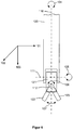
- Such an "active trocar" according to the invention can move the surgical instrument around the pivotal point at least in two degrees of freedom (direction 101 and 102), as in FIG FIG. 6 is shown.
- the surgical instruments have a total of 7 degrees of freedom: 3 degrees of freedom (degrees of freedom 101, 102, and 103 in accordance with FIG FIG. 6 ) are realized by a motor coupling of the operating instrument used in the trocar with corresponding drive units, another 4 degrees of freedom (degrees of freedom 104, 105, 106 and 107 according to FIG. 6 ) are realized by a drive unit at the end of each operational instrument used.
- the pivotal point is defined by the active trocar itself, the position of the pivotal point before starting the operation is determined by a pre-positioning of the active trocar. A rearrangement of the patient after the beginning of the surgical procedure is thus possible, since the pivotal point is structurally connected to the positioning devices according to the invention or active trocars and retained during a rearrangement in relation to the active positioning device, ie, the pivotal point relative to the instrument and the carrier plate and leadership is always maintained.
- the system can be made significantly smaller and lighter. This allows a simpler transfer of the entire system, for example to another operating room, and thus greater flexibility and utilization of utilization.
- FIG. 1 shows an active positioning of a surgical instrument according to the invention, which is mounted on a robot arm.
- 4 surgical instruments are usually used, including 3 surgical instruments and 1 camera or endoscope, which are controlled by the operator via the telemanipulator system.
- 4 versions of an active trocar or an active positioning device are present in the system.
- Each active trocar is supported by a robot arm 1, which can be provided with joints 2 weight free. This support mechanism should accordingly be provided for each active trocar. All mounting mechanisms can be mounted on a common support (see FIG. 4 ), or be attached to separate carriers. An attachment to separate carriers may be useful, for example, if the arrangement of the trocars for the surgical procedure requires this.
- a support plate 3 of the active trocar is firmly connected.
- This carrier plate 3 is in turn firmly connected to a port device 4.
- the port device 4 is in turn connected via a compensation element 5 with the guide device 6.
- About the compensation element 5 is a movement (inclination) of the guide device 6 relative to the port device 4 possible.
- the guide device 6 receives the surgical instrument 8.
- the abdominal cavity is "inflated" by the introduction of a gas (carbon dioxide, CO2) to allow the surgeon more freedom of movement for the actual surgical procedure. So that the gas can not escape, the seal 7 is required.
- the actuators or actuators 9, 12 are arranged orthogonal to each other.
- a ball lever mechanism 10, 11 and 13, 14 forces are applied to the upper end of the guide means 6, so that it can be moved relative to the port device 4 in 2 axes (x, y) independently.
- Another actuator 15 is attached to the upper end of the guide device 6. About an actuator mechanism consisting of terminal 16, pulley 17, terminal 18 and corresponding cables 19, the translational movement of the instrument in the z-direction is realized.
- a telescope system 20 is connected via the holding device 21 with an instrument drive unit 22 such that a rotational movement ⁇ of the surgical instrument 8 about the z-axis is prevented.
- the rotational movement ⁇ of the surgical instrument 8 is realized by a rotary actuator 23, which is connected to the shaft of the surgical instrument 8.
- the instrument actuators 24, 25 and 26 realize the movements of the surgical instrument 8 in the degrees of freedom 105, 106 and 107, see FIG. 6 ,
- FIG. 2 shows an active positioning device according to the invention as in FIG. 1 in addition provided with an insufflation port consisting of a delivery tube (29) which opens below the seal (7) in the cavity of the trocar (6) and a connection and valve assembly (30).
- An insufflation device is expediently connected to the connection and valve assembly. This pumps a gas, usually CO2 via the valve assembly (30) and the associated supply tube (29) in the abdominal cavity of the patient.
- the seal (7) prevents accidental escape of the gas from the abdomen of the patient into the environment.
- the seal (7) is expediently designed in such a way that, when the instrument (8) is completely removed from the trocar (6), it closes off gastight, ie even when the instrument is removed, no insufflation gas escapes into the environment.
- FIG. 3 shows a plan view of the active positioning according to FIG. 1 ;
- FIG. 4 shows a schematic view of a portion of the inventive robotic surgical system during surgery on the human body; in the FIG. 5 Robot arms described in detail are supported by base supports, here by way of example 300a, 300b and 300c, in such a way that these base supports are held in an eg arcuate guide rail 311 in connection with 312 and 313 and can be positioned independently relative to one another.
- base supports here by way of example 300a, 300b and 300c, in such a way that these base supports are held in an eg arcuate guide rail 311 in connection with 312 and 313 and can be positioned independently relative to one another.
- the preferably arcuate shape of the guide has the advantage of pre-positioning the robot arms in an arc above the abdominal wall 27 in accordance with the typical anatomy of a patient.
- FIG. 5 shows a schematic view of a robot arm according to the invention.
- the robot arm consists of a plurality of links 303, 306 and 309, which are connected to one another via joints, which is an arrangement of the coupling surface 310 to an active positioning according to FIG. 1 or 2 is possible.
- the robot arm itself is over Joint 301, which allows a pivoting movement about the axis of rotation 302 by +/- 90 °, attached to a base support 300.
- the first sub-member 303 of the robot arm leads to a further joint 304, which has an axis of rotation 305, preferably orthogonal to the axis of rotation 302.
- a further sub-member 306 of the robot arm is connected, which enables a pivoting movement 308 via a further joint 307, preferably orthogonal to the axis of rotation 302 and orthogonal to the axis of rotation 305.
- the third sub-member 309 of the robot arm has at its distal end a coupling surface 310, to which by producing a suitable positive and preferably also positive connection, the active positioning device according to FIG. 1 or 2 can be attached to the module 3.
- the joints 301, 304, 307 can be active, ie provided with actuators, as well as passive.
- the joints 301, 304, 307 are provided with absolute position encoders, so that the position or orientation of the robot arms and the active positioning device coupled thereto in space is known.
- the signals of the absolute position sensor can preferably be offset in the control unit 202 with one another in such a way that, knowing the geometry and the current position of the active positioning device according to FIG FIG. 1 or 2 an imminent collision of the various robot arms with each other or the collision of a robot arm with an active positioning of another robot arm is detected and the user can be issued a collision warning via the control and display unit 200.
- control unit 202 can actively avoid the potential collision of the various robot arms with one another, or the collision of a robot arm with an active positioning device of another robot arm by a change in the setting command given by the operating and display unit 200.
- the hinges 301, 304, 307 are preferably secured with a device against unintentional adjustment of the joint position.
- FIG. 6 shows a surgical instrument as a possible part of the invention.
- the arrangement has 7 degrees of freedom. These are realized by a translatory movement of the instrument shaft (120) in the x-direction (101) and y-direction (102). These movements cause the instrument to tilt around the pivot point.
- the instrument shaft (120) can be moved in the z-direction (103).
- the instrument shaft (120) can be rotated about its own instrument axis (110) in the direction of movement (104).
- the instrument tip consists of at least 3 mutually movable assemblies.
- a first assembly (121) is arranged to be tiltable about the axis of rotation (111) in the direction of rotation (105) to the instrument shaft (120).
- This module (121) itself carries two modules (122, 123), which are independently tiltable about the axis of rotation (112) in the direction of rotation (106) are arranged.
- the angle (107) between the two assemblies (122, 123) is changed about the axis of rotation (112).
- a gripping, clamping or cutting movement can be performed, depending on how the assemblies (122, 123) are designed mechanically.
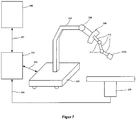
- FIG. 7 and FIG. 8 show embodiments of the robot system according to the invention with one or four robot arms and with a (212a) and 4 (212a-d) inventive active positioning.
- the following explanations relate to an embodiment with a robot arm gem.
- FIG. 7 The active positioning device (212a) is connected to a sheet guide (209) via a pre-positioning device consisting of the assemblies 210 and 211.
- the pre-positioning device can be passive, ie realized by manual adjustment or preferably also actively, ie by equipping the joints (211) with active actuators.
- the pre-positioning device itself is held by means of a suitable holder, for example as a sheet guide (209).
- This sheet guide (209) can be positioned by means of the joint (208) to the patient.
- the boom (207) is connected to the mobile carrier system (205) and thus allows positioning of the entire carrier system (consisting of 205, 207..212a) relative to the operating table (206).
- the operating and display unit (200) outputs the current status of the pre-positioning device (210, 211) to the operator.
- the operator can enter control commands which via a suitable data connection (201) to the control unit (202) and from this to the Active Positioning device (212 a), to the Vorpositionier leads (210, 211) and the sheet guide (209) is sent for further processing.
- the control unit (202) is connected to the carrier system via a suitable data connection (203).
- the operating table (206) can also be connected to the control unit (202) via the data connection (204) in order to process this change in position in the control unit in the event of a change in the operating table position, for example the height, and an active control Tracking the Active Positioner (212a) via the Vorposition réelles worn (210, 211) and / or to achieve the position of the sheet guide (209).
- a change in the operating table position for example the height
- FIG. 9 such as FIG. 10 shows an active positioning device according to the invention for two surgical instruments on a common port, which is mounted on a robot arm.
- a minimally invasive, laparoscopic procedure usually 4 Operating instruments are used, including 3 surgical instruments and 1 camera or endoscope, which are controlled by the telemanipulator system by the surgeon.
- two surgical instruments can be introduced into the body of the patient via a common port (single port) by means of two separate guide devices and can be independently controlled by means of one active positioning device per surgical instrument.
- each active trocar is stored weight-free via a robot arm 31, which can be provided with joints 32.
- This support mechanism should accordingly be provided for each active trocar. All mounting mechanisms can be mounted on a common support (see FIG. 4 ), or be attached to separate carriers. An attachment to separate carriers may be useful, for example, if the arrangement of the trocars for the surgical procedure requires this.
- a support plate 33 of the active trocar is firmly connected.
- This carrier plate 33 is in turn firmly connected to a port device 34.
- the port device 34 is in turn connected via a compensation element 35 with the guide means 36 and 59.
- About the compensation element 35 is a movement (inclination) of the guide means 36 and 59 relative to the port device 34 possible.
- the guide means 36 and 59 receive the surgical instruments 38 and 61.
- About the sealing rings 37 and 60 is a gas-tight sealing of the surgical instruments 38 and 61 against the guide means 36 and 59.
- a gas carbon dioxide, CO2
- the abdominal cavity by inflating a gas (carbon dioxide, CO2) is "inflated" to the surgeon more freedom of movement for the actual to allow surgical intervention. So that the gas can not escape, the seal 37 or 60 is required.
- the actuators or actuators 39, 42 and 62, 65 are each arranged orthogonal to each other. Via ball lever mechanisms 40, 41, 43, 44 and 63, 64, 66, 67 forces are exerted on the upper end of the guide means 36 and 59, respectively, so that they move relative to the port means 34 in 2 axes (x, y) independently of each other to let.
- actuators 45, 68 are mounted on the upper ends of the guide means 36 and 59.
- actuator mechanisms consisting of terminal 46, pulley 47, terminal 48 and corresponding cables 49, the translational movement of the instrument 38 is realized in the z direction.
- actuator mechanisms consisting of terminal 69, pulley 70, terminal 71 and corresponding cables 72, the translational movement of the instrument 61 is realized in the z-direction.
- a telescope system 50 is connected via the holding device 51 with an instrument drive unit 52 such that a rotational movement ⁇ of the surgical instrument 38 about the z-axis is prevented.
- the rotational movement ⁇ of the surgical instrument 38 is realized by a rotary actuator 53, which is connected to the shaft of the surgical instrument 38.
- the instrument actuators 54, 55 and 56 realize the movements of the surgical instrument 38 in the degrees of freedom 105, 106 and 107, see FIG. 6 ,
- a telescope system 73 is connected via the holding device 74 with an instrument drive unit 75 such that a rotational movement ⁇ of the surgical instrument 61 about the z-axis is prevented.
- the rotational movement ⁇ of the surgical instrument 61 is realized by a rotary actuator 76, which is connected to the shaft of the surgical instrument 61.
- the instrument actuators 77, 78 and 79 realize the movements of the surgical instrument 61 in the degrees of freedom 105, 106 and 107, see FIG. 6 ,
- FIG. 10 shows a plan view of the active positioning according to FIG. 9 , from which it can be seen that the two guide means 36, 59 extend through the common compensating element 35.
- the first adjusting device 39, 40, 41, 42, 43, 44 for the first guide device 36 and the second adjusting device 62, 63, 64, 65, 66, 67 of the second guide device 59 for the two surgical instruments are arranged in such a way that that obstruction or restriction of the two respective adjustment is avoided.
- the present invention thus relates to an active positioning device, in which one or more surgical instruments can be used through a trocar for minimally invasive surgery.
Landscapes
- Health & Medical Sciences (AREA)
- Life Sciences & Earth Sciences (AREA)
- Surgery (AREA)
- Engineering & Computer Science (AREA)
- Nuclear Medicine, Radiotherapy & Molecular Imaging (AREA)
- General Health & Medical Sciences (AREA)
- Veterinary Medicine (AREA)
- Public Health (AREA)
- Animal Behavior & Ethology (AREA)
- Biomedical Technology (AREA)
- Heart & Thoracic Surgery (AREA)
- Medical Informatics (AREA)
- Molecular Biology (AREA)
- Robotics (AREA)
- Oral & Maxillofacial Surgery (AREA)
- Pathology (AREA)
- Mechanical Engineering (AREA)
- Manipulator (AREA)
Description
- Die vorliegende Erfindung betrifft eine aktive Positioniereinrichtung eines chirurgischen Instruments und ein chirurgisches Robotersystem bzw. Telemanipulator für die minimal-invasive Chirurgie und insbesondere der Laparoskopie.
- Robotersysteme oder auch Telemanipulatoren für die minimal-invasive Chirurgie, insbesondere für die laparoskopische Chirurgie, ersetzen die vom Chirurgen üblicherweise manuell geführten Operations-Instrumente, wie beispielsweise chirurgische Instrumente, Endoskop bzw. Kamera, durch eine motorische Positionierung. Die einzusetzenden Operations-Instrumente werden über einen bzw. mehrere Trokare in das Innere eines Patienten geführt. Als Trokar wird ein Instrument bezeichnet, mit dessen Hilfe der Chirurg in der minimal-invasiven Chirurgie ein Zugang zu der Körperhöhle des Patienten (üblicherweise des Bauchraumes oder des Brustraumes) schafft, wobei der Zugang durch ein Rohr, einen sog. Tubus, offengehalten wird. Die in dem Robotersystem vorgesehene Bewegungsmechanik und Steuerungslogik ermöglicht die Bewegung der Operations-Instrumente um einen Pivotalpunkt herum in 2 Freiheitsgraden (x, y) sowie eine translatorische Bewegung der Operations-Instrumente entlang der Instrumentenachse (z). Als Pivotalpunkt wird der invariante Punkt der Bewegung in 2 Freiheitsgraden (x, y) bezeichnet. Dieser Pivotalpunkt liegt idealerweise im Durchstoßpunkt des Trokars durch die Bauchdecke des Patienten. Die Steuerungslogik eines Robotersystems muss den Pivotalpunkt kennen bzw. der Pivotalpunkt muss durch die konstruktive Ausführung der Bewegungsmechanik definiert sein, um eine Bewegung des Operations-Instrumentes so zu begrenzen, dass die biomechanische Belastung des Gewebes um den Trokar herum möglichst gering ist.
- Aus dem Stand der Technik bekannte Robotersysteme basieren auf Roboterarmen zur passiven Vorpositionierung und aktiven Bewegung eines Operations-Instrumentes. Eine Lösung mit Roboterarmen aus dem Stand der Technik, die eine passive Vorpositionierung und eine aktive Bewegung der Operations-Instrumente rund um den Pivotalpunkt realisieren, benötigen einerseits einem großen Bauraum und andererseits können die Bewegungsabläufen der Roboterarmen zu einer Kollision führen.
- Während eines minimal-invasiven chirurgischen Eingriffs werden mindestens zwei, in der Regel drei bis vier chirurgische Instrumente, wie Greifer, Schere, Nadelhalter, Sezierer), sowie eine Kamera bzw. ein Endoskop verwendet, die jeweils über einen gesonderten Trokar in das Körperinnere des Patienten geführt werden. Das bedeutet, dass für jedes eingesetzte Operations-Instrument ein Roboterarm vorhanden ist, der die passive Vorpositionierung und die aktive Bewegung des Instruments steuert.
-
US2011/0319913 offenbart ein Gerät zur Implantation mit einer Plattform und einem Parallelroboter. - Nachteil der Lösungen aus dem Stand der Technik ist, dass die Position des Patienten vor Beginn der Operation fixiert werden muss und eine Umlagerung des Patienten während der Operation nahezu nicht möglich ist.
- Ein weiterer, bereits erwähnter, Nachteil ist der große Bauraum, den die bekannten Robotersysteme erfordern.
- Aufgabe der vorliegenden Erfindung ist es daher, eine aktive Positioniereinrichtung eines chirurgischen Instruments und ein chirurgisches Robotersystem bereitzustellen, die bzw. das eine hohe Variabilität vorsieht und nur einen geringen Bauraum benötigt bzw. kleiner und leichter in seiner Ausführung ist.
- Eine weitere Aufgabe der vorliegenden Erfindung ist es, ein Robotersystem bereitzustellen, das eine Umlagerung des Patienten während einer Operation ermöglicht, insbesondere ohne dabei die Bewegungsfreiheit des chirurgischen Instruments nach der Umlagerung einzuschränken.
- Diese Aufgaben werden durch die vorliegende Erfindung gemäß Anspruch 1 durch eine aktive Positioniereinrichtung eines chirurgischen Instruments und gemäß Anspruch 9 durch ein chirurgisches Robotersystem gelöst.
- Ein Gegenstand der vorliegenden Erfindung betrifft eine aktive Positioniereinrichtung eines chirurgischen Instruments zur Verwendung an einem Roboterarm nach Anspruch 1. Bevorzugte Ausführungsformen sind in den abhängigen Ansprüchen beschrieben.
- In einer bevorzugten Ausführungsform ist das Ausgleichselement in seiner Geometrie derart variierbar, dass ein frei wählbarer Winkel sowohl in x- als auch in y-Richtung zwischen der Porteinrichtung und der Führungseinrichtung im Hinblick auf die zueinander kongruente Ausgangslage einstellbar ist, wobei das Ausgleichselement insbesondere aus einem elastischen Material ausgebildet ist.
- Erfindungsgemäß weist die Verstelleinrichtung zumindest zwei ansteuerbare Aktuatoren auf, welche insbesondere als zueinander orthogonal angeordnete Stellantriebe ausgeführt sind, wobei ein Kugelhebelmechanismus zwischen der Führungseinrichtung und der Trägerplatte oder der Porteinrichtung derart vorgesehen ist, dass durch die Stellantriebe mittels des Kugelhebelmechanismus die Führungseinrichtung gegenüber der Ausgangslage in x-Richtung und y-Richtung unabhängig voneinander positionierbar ist.
- Bei einer ebenfalls bevorzugten Ausführungsform ist an der Führungseinrichtung eine Translationsverstelleinrichtung vorgesehen, die mit dem chirurgischen Instrument derart verbunden ist, dass der Schaft des chirurgischen Instruments in z-Richtung bewegbar ist. Bevorzugt bewegt die Translationsverstelleinrichtung mittels eines Teleskopsystems 20 und/oder Seilzugsystems den Schaft des chirurgischen Instruments in z-Richtung.
- In einer ferner bevorzugten Ausführungsform ist an dem chirurgischen Instrument eine Instrumentenantriebseinheit vorgesehen, welche einen Rotationsaktuator umfasst, durch den der Schaft des chirurgischen Instruments gegenüber der Ausgangslage um die z-Richtung drehbar variiert wird. Bevorzugt weist die Instrumentenantriebseinheit drei Instrumentenaktuatoren auf, durch welche die am distalen Ende angebrachte Wirkeinheit des chirurgischen Instruments in drei weiteren Freiheitsgraden variierbar ist. Insbesondere bevorzugt ist die Instrumentenantriebseinheit über eine Halteeinrichtung an dem proximalen Ende des Teleskopsystems angeordnet.
- Ein weiterer Gegenstand der vorliegenden Erfindung betrifft ein chirurgisches Robotersystem zur Durchführung von operativen Eingriffen am menschlichen Körper nach Anspruch 9.
- In einer bevorzugten Ausführungsform des Robotersystems ist das Ausgleichselement in seiner Geometrie derart variierbar, dass ein frei wählbarer Winkel sowohl in x- als auch in y-Richtung zwischen der Porteinrichtung und der Führungseinrichtung im Hinblick auf die zueinander kongruente Ausgangslage einstellbar ist, wobei das Ausgleichselement insbesondere aus einem elastischen Material ausgebildet ist.
- Weitere vorteilhafte Ausgestaltungen des erfindungsgemäßen chirurgischen Robotersystems ergeben sich aus den Unteransprüchen analog zu der aktiven Positioniereinrichtung für ein chirurgisches Instrument. Dies ergibt sich insbesondere dadurch, dass die erfindungsgemäße aktive Positioniereinrichtung mit einem Robotersystem kombiniert bzw. nachgerüstet werden kann.
- Erfindungsgemäß können die Begriffe Robotersystem und Telemanipulator synonym verwendet werden.
- Die vorliegende Erfindung wird rein beispielhaft durch die beigefügten Figuren realisiert. Es zeigt:
-
Figur 1 eine schematische Ansicht der erfindungsgemäßen aktiven Positioniereinrichtung eines chirurgischen Instruments, welche an einem Roboterarm angebracht ist; -
Figur 2 eine schematische Teilansicht der erfindungsgemäßen aktiven Positioniereinrichtung mit Anschlussmöglichkeit zur Einleitung von Insufflationsgas, in der Regel CO2; -
Figur 3 eine Draufsicht der aktiven Positioniereinrichtung nachFigur 1 ; -
Figur 4 eine schematische Ansicht eines Teils des erfindungsgemäßen chirurgischen Robotersystems während einer Operation am menschlichen Körper; -
Figur 5 eine schematische Ansicht eines Roboterarms gemäß der Erfindung; -
Figur 6 eine schematische Ansicht eines chirurgischen Instruments, welches Bestandteil der Erfindung sein kann; -
Figur 7 eine schematische Ansicht eines Robotersystems mit einem Roboterarm und aktiven Positioniereinrichtungen gemäß der Erfindung; und -
Figur 8 eine schematische Ansicht eines Robotersystems mit 4 Roboterarmen und aktiven Positioniereinrichtungen gemäß der Erfindung. -
Figur 9 eine schematische Ansicht der erfindungsgemäßen aktiven Positioniereinrichtung für zwei chirurgische Instrumente und einem gemeinsamen Port, welche an einem Roboterarm angebracht ist; -
Figur 10 eine Draufsicht der aktiven Positioniereinrichtung nachFigur 9 - Die vorliegende Erfindung betrifft gemäß einem Aspekt ein chirurgisches Robotersystem bzw. einen Telemanipulator, bei dem eine passive Vorpositionierung des Trokars bzw. der aktiven Positioniereinrichtung mit einer aktiven Steuerung bzw. Motorisierung des Trokars zur Bewegung eines Operations-Instrumentes kombiniert wird. Ein solcher erfindungsgemäßer "aktiver Trokar" kann das Operations-Instrument um den Pivotalpunkt zumindest in 2 Freiheitsgraden (Richtung 101 und 102) bewegen, wie in
Figur 6 dargestellt ist. Erfindungsgemäß weisen die Operations-Instrumente insgesamt 7 Freiheitsgrade auf: 3 Freiheitsgrade (Freiheitsgrade 101, 102, und 103 gemäßFigur 6 ) werden durch eine motorische Kopplung des in den Trokar eingesetzten Operations-Instruments mit entsprechenden Antriebseinheiten realisiert, weitere 4 Freiheitsgrade (Freiheitsgrade 104, 105, 106 und 107 gemäßFigur 6 ) werden durch eine Antriebseinheit am Ende eines jeden eingesetzten Operations-Instrumentes realisiert. - Da der Pivotalpunkt durch den aktiven Trokar selbst definiert wird, wird die Lage des der Pivotalpunktes vor Beginn der Operation über eine Vorpositionierung des aktiven Trokars festgelegt. Eine Umlagerung des Patienten nach dem Beginn des chirurgischen Eingriffs ist damit möglich, da der Pivotalpunkt mit den erfindungsgemäßen Positioniereinrichtungen bzw. aktiven Trokaren konstruktiv verbunden ist und bei einer Umlagerung gegenüber der aktiven Positioniereinrichtung beibehalten wird, d.h., dass der Pivotalpunkt gegenüber dem Instrument und der Trägerplatte sowie Führungseinrichtung stets beibehalten wird.
- Weiterhin kann durch den Verzicht auf Roboterarme zur aktiven Positionierung der Instrumente das System deutlich kleiner und leichter ausgeführt werden. Damit ist ein einfacherer Transfer des Gesamtsystems, beispielsweise in einen anderen Operations-Saal, und damit eine höhere Flexibilität und Nutzungsauslastung möglich.
- Die vorliegende Erfindung wird nachfolgend im Detail unter Bezugnahme auf die Figuren beschrieben:
-
Figur 1 zeigt eine erfindungsgemäße aktive Positioniereinrichtung eines chirurgischen Instruments, die an einem Roboterarm angebracht ist. Während eines minimal-invasiven, laparoskopischen Eingriffs kommen in der Regel 4 Operations-Instrumente zum Einsatz, hiervon 3 chirurgische Instrumente und 1 Kamera bzw. Endoskop, die über das Telemanipulatorsystem vom Operateur gesteuert werden. Erfindungsgemäß sind demnach vorzugsweise 4 Ausführungen eines aktiven Trokars bzw. einer aktiven Positioniereinrichtung im System vorhanden. Es versteht sich jedoch, dass auch Ausführungsformen mit 1 bis 3 oder mehr als 4 aktiven Trokaren unter den Schutzbereich der Erfindung fallen. Jeder aktive Trokar wird über einen Roboterarm 1, welche mit Gelenken 2 versehen sein kann gewichtskraftfrei gelagert. Dieser Halterungsmechanismus ist demnach für jeden aktiven Trokar vorzusehen. Alle Halterungsmechanismen können an einem gemeinsamen Träger (sieheFigur 4 ), oder an getrennten Trägern befestigt werden. Eine Befestigung an getrennten Trägern kann beispielsweise sinnvoll sein, wenn die Anordnung der Trokare für den chirurgischen Eingriff dies erfordert. - Mit dem Roboterarm 1 ist eine Trägerplatte 3 des aktiven Trokars fest verbunden. Diese Trägerplatte 3 ist wiederum fest mit einer Porteinrichtung 4 verbunden. Die Porteinrichtung 4 ist seinerseits über ein Ausgleichselement 5 mit der Führungseinrichtung 6 verbunden. Über das Ausgleichselement 5 ist eine Bewegung (Neigung) der Führungseinrichtung 6 gegenüber der Porteinrichtung 4 möglich. Durch diese Bewegung wird die pivotale Bewegung des chirurgischen Instruments 8 realisiert. Die Führungseinrichtung 6 nimmt das chirurgische Instrument 8 auf. Über einen Dichtungsring 7 erfolgt eine gasdichte Abdichtung des chirurgischen Instrumentes 8 gegenüber der Führungseinrichtung 6. In der Laparoskopie wird der Bauchraum durch Einleitung eines Gases (Kohlendioxid, CO2) "aufgepumpt", um dem Operateur mehr Bewegungsfreiheit für den eigentlichen chirurgischen Eingriff zu ermöglichen. Damit das Gas nicht entweichen kann, ist die Abdichtung 7 erforderlich.
- Die Aktuatoren bzw. Stellantriebe 9, 12 sind orthogonal zueinander angeordnet. Über einen Kugelhebelmechanismus 10, 11 sowie 13, 14 werden Kräfte auf das obere Ende der Führungseinrichtung 6 ausgeübt, so dass diese sich relativ zur Porteinrichtung 4 in 2 Achsen (x, y) unabhängig voneinander bewegen lässt.
- Ein weiterer Stellantrieb 15 ist am oberen Ende der Führungseinrichtung 6 angebracht. Über eine Stellantriebsmechanik bestehend aus Klemme 16, Umlenkrolle 17, Klemme 18 und entsprechende Seilzüge 19 wird die translatorische Bewegung des Instrumentes in z-Richtung realisiert.
- Ein Teleskopsystem 20 ist über die Halteeinrichtung 21 mit einer Instrumentenantriebseinheit 22 derart verbunden, das eine Rotationsbewegung α des chirurgischen Instrumentes 8 um die z-Achse verhindert wird. Die Rotationsbewegung α des chirurgischen Instruments 8 wird durch einen Rotationsaktuator 23, welcher mit dem Schaft des chirurgischen Instruments 8 verbunden ist, realisiert. Die Instrumentenaktuatoren 24, 25 und 26 realisieren die Bewegungen des chirurgischen Instruments 8 in den Freiheitsgraden 105, 106 und 107, siehe
Figur 6 . -
Figur 2 zeigt eine erfindungsgemäße aktive Positioniereinrichtung wie inFigur 1 , zusätzlich versehen mit einem Insufflations-Anschluss bestehend aus einer Zuführungsröhre (29), welche unterhalb der Dichtung (7) in den Hohlraum des Trokars (6) mündet sowie einer Anschluss- und Ventilbaugruppe (30). An die Anschluss- und Ventilbaugruppe wird zweckmäßigerweise ein Insufflations-Gerät angeschlossen. Dieses pumpt ein Gas, im Regelfall CO2 über die Ventilbaugruppe (30) und die damit verbundene Zuführungsröhre (29) in den Bauchraum des Patienten. Die Dichtung (7) verhindert ein ungewolltes Entweichen des Gases aus dem Bauchraum des Patienten in die Umgebung. Die Dichtung (7) ist zweckmäßigerweise so ausgeführt, dass diese bei vollständigen Entfernen des Instruments (8) aus dem Trokar (6) diesen gasdicht abschließt, d.h. auch bei entnommenen Instrument entweicht kein Insufflationsgas in die Umgebung. -
Figur 3 zeigt eine Draufsicht der aktiven Positioniereinrichtung gemäßFigur 1 ; -
Figur 4 zeigt eine schematische Ansicht eines Teils des erfindungsgemäßen chirurgischen Robotersystems während einer Operation am menschlichen Körper; die inFigur 5 detailliert beschriebenen Roboterarme werden durch Basishalterungen, hier exemplarisch 300a, 300b und 300c, derart gehaltert, das diese Basishalterungen in einer z.B. bogenförmig ausgeprägten Führungsschiene 311 in Verbindung mit 312 und 313 gehaltert werden und relativ zueinander unabhängig positioniert werden können. An der Koppelfläche 310 des Roboterarms wird die Aktive Positioniereinrichtung gemäßFigur 1 bzw. 2 an der Baugruppe 3 gehaltert. Die vorzugsweise bogenförmige Gestalt der Führung hat den Vorteil die Roboterarme gemäß der typischen Anatomie eines Patienten in einem Bogen oberhalb der Bauchdecke 27 vorzupositionieren. -
Figur 5 zeigt eine schematische Ansicht eines Roboterarms gemäß der Erfindung; Der Roboterarm besteht aus mehreren Gliedern 303, 306 und 309, welche über Gelenke miteinander so verbunden sind, das eine Anordnung der Koppelfläche 310 zu einer Aktiven Positioniereinrichtung gemäßFigur 1 bzw. 2 möglich ist. Der Roboterarm selbst ist über ein Gelenk 301, welches eine Schwenkbewegung um die Drehachse 302 um +/- 90° ermöglicht, an einer Basishalterung 300 befestigt. Das erste Teilglied 303 des Roboterarms führt zu einem weiteren Gelenk 304, welches eine Drehachse 305, vorzugsweise orthogonal zur Drehachse 302, aufweist. Über das Gelenk 304 ist ein weiteres Teilglied 306 des Roboterarms verbunden, welches über ein weiteres Gelenk 307 eine Schwenkbewegung 308 ermöglicht, vorzugsweise orthogonal zur Drehachse 302 und orthogonal zur Drehachse 305, angeordnet. Das dritte Teilglied 309 des Roboterarms weist an seinem distalen Ende eine Koppelfläche 310 auf, an welche durch Herstellung einer geeigneten kraft- und vorzugsweise auch formschlüssigen Verbindung die Aktive Positionierungseinrichtung gemäßFigur 1 bzw. 2 an der Baugruppe 3 befestigt werden kann. Die Gelenke 301, 304, 307 können sowohl aktiv, d.h. versehen mit Stellantrieben, als auch passiv ausgeführt sein. Die Gelenke 301, 304, 307 sind mit absoluten Positionsgebern versehen, so dass die Lage bzw. Orientierung der Roboterarme und der jeweils daran angekoppelten Aktiven Positioniereinrichtung im Raum bekannt ist. Die Signale der absoluten Positionsgeber können vorzugsweise in der Steuereinheit 202 so miteinander verrechnet werden, dass unter Kenntnis der Geometrie und der aktuellen Stelllage der Aktiven Positioniereinrichtung gemäßFigur 1 bzw. 2 eine drohende Kollision der verschiedenen Roboterarme untereinander bzw. die Kollision eines Roboterarmes mit einer Aktiven Positioniereinrichtung eines anderen Roboterarmes erkannt wird und über die Bedien- und Anzeigeeinheit 200 dem Anwender eine Kollisionswarnung ausgegeben werden kann. In einer weiteren Ausführungsform kann die Steuereinheit 202 die potentielle Kollision der verschiedenen Roboterarme untereinander, bzw. die Kollision eines Roboterarmes mit einer Aktiven Positioniereinrichtung eines anderen Roboterarmes durch eine Änderung des durch die Bedien- und Anzeigeeinheit 200 vorgegebenen Stellbefehls aktiv vermeiden. In einer passiven Ausführung sind die Gelenke 301, 304, 307 vorzugsweise mit einer Einrichtung gegen unbeabsichtigtes Verstellen der Gelenkposition gesichert. -
Figur 6 zeigt ein chirurgischen Instruments als einen möglichen Bestandteil der Erfindung. Insgesamt weist die Anordnung 7 Freiheitsgrade auf. Diese werden realisiert durch eine translatorische Bewegung des Instrumentenschaftes (120) in x-Richtung (101) und y-Richtung (102). Diese Bewegungen bewirken ein Verkippen des Instrumentes um den Pivotpunkt. Weiterhin kann der Instrumentenschaft (120) in z-Richtung (103) bewegt werden. Der Instrumentenschaft (120) kann um seine eigene Instrumentenachse (110) in der Bewegungsrichtu.ng (104) rotierend bewegt werden. Die Instrumentenspitze besteht aus mindestens 3 zueinander beweglichen Baugruppen. Eine erste Baugruppe (121) ist dabei um die Drehachse (111) in der Drehrichtung (105) kippbar zum Instrumentenschaft (120) beweglich angeordnet. Diese Baugruppe (121) trägt selbst zwei Baugruppen (122, 123), welche unabhängig voneinander kippbar um die Drehachse (112) in der Drehrichtung (106) angeordnet sind. Durch Drehbewegung der Baugruppe (122) relativ zur Baugruppe (123) wird der Winkel (107) zwischen den beiden Baugruppen (122, 123) um die Drehachse (112) verändert. Damit kann eine Greif-, Klemm- oder Schneidbewegung ausgeführt werden, je nachdem wie die Baugruppen (122, 123) mechanisch gestaltet sind. -
Figur 7 undFigur 8 zeigen Ausführungsformen des erfindungsgemäßen Robotersystems mit einem bzw. 4 Roboterarmen und mit einer (212a) bzw. 4 (212a-d) erfindungsgemäßen aktiven Positioniereinrichtungen. Die nachfolgenden Erläuterungen beziehen sich auf eine Ausführungsform mit einem Roboterarm gem.Figur 7 . Die aktive Positioniereinrichtung (212a) ist über eine Vorpositionierungseinrichtung bestehend aus den Baugruppen 210 und 211 mit einer Bogenführung (209) verbunden. Die Vorpositionierungseinrichtung kann passiv, d.h. durch manuelle Verstellung oder vorzugsweise auch aktiv, d.h. durch Ausstattung der Gelenke (211) mit aktiven Stellantrieben realisiert sein. Die Vorpositionierungseinrichtung selbst wird mittels einer geeigneten Halterung, z.B. als Bogenführung (209) gehaltert. Diese Bogenführung (209) kann mittels des Gelenkes (208) zum Patienten positioniert werden. Der Ausleger (207) ist verbunden mit dem fahrbaren Trägersystem (205) und ermöglicht damit eine Positionierung des gesamten Trägersystems (bestehend aus 205, 207..212a) relativ zum OP-Tisch (206). Über die Bedien- und Anzeigeeinheit (200) wird dem Bediener der aktuelle Status der Vorpositioniereinrichtung (210, 211) ausgegeben. Über die Bedien- und Anzeigeeinheit (200) kann der Bediener Steuerbefehle eingeben, welche über eine geeignete Datenverbindung (201) an die Steuereinheit (202) und von dieser an die Aktive Positioniereinrichtung (212a), an die Vorpositioniereinrichtung (210, 211) sowie an die Bogenführung (209) zur weiteren Verarbeitung gesendet werden. Die Steuereinheit (202) ist über eine geeignete Datenverbindung (203) mit dem Trägersystem verbunden. Der OP-Tisch (206) kann steuerungstechnisch über die Datenverbindung (204) ebenfalls mit der Steuereinheit (202) verbunden sein, um bei einer Veränderung der OP-Tisch - Position, z.B. der Höhe, diese Positionsänderung in der Steuereinheit zu verarbeiten und eine aktive Nachführung der Aktiven Positioniereinrichtung (212a) über die Vorpositionierungseinrichtung (210, 211) und/oder die Lage der Bogenführung (209) zu erzielen. Damit können Veränderungen der Patientenposition aufgrund einer Positionsveränderung des OP-Tisches (206) aktiv ausgeglichen werden. -
Figur 9 sowieFigur 10 zeigt eine erfindungsgemäße aktive Positioniereinrichtung für zwei chirurgische Instrumente an einem gemeinsamen Port, die an einem Roboterarm angebracht ist. Während eines minimal-invasiven, laparoskopischen Eingriffs kommen in der Regel 4 Operations-Instrumente zum Einsatz, hiervon 3 chirurgische Instrumente und 1 Kamera bzw. Endoskop, die über das Telemanipulatorsystem vom Operateur gesteuert werden. Erfindungsgemäß können daher 2 chirurgische Instrumente über einen gemeinsamen Port (single-Port) mittels zwei separaten Führungseinrichtungen in den Körper des Patienten eingeführt werden und mittels je einer aktiven Positioniereinrichtung pro chirurgischen Instrument voneinander unabhängig gesteuert werden. Es sind demnach vorzugsweise 2 Ausführungen eines aktiven Trokars für eine Single-Port-Zugang bzw. einer aktiven Positioniereinrichtung im System vorhanden. Es versteht sich jedoch, dass auch Ausführungsformen mit 1 oder mehr als 2 aktiven Trokaren für einen Single-Port-Zugang unter den Schutzbereich der Erfindung fallen. Jeder aktive Trokar wird über einen Roboterarm 31, welche mit Gelenken 32 versehen sein kann gewichtskraftfrei gelagert. Dieser Halterungsmechanismus ist demnach für jeden aktiven Trokar vorzusehen. Alle Halterungsmechanismen können an einem gemeinsamen Träger (sieheFigur 4 ), oder an getrennten Trägern befestigt werden. Eine Befestigung an getrennten Trägern kann beispielsweise sinnvoll sein, wenn die Anordnung der Trokare für den chirurgischen Eingriff dies erfordert. - Mit dem Roboterarm 31 ist eine Trägerplatte 33 des aktiven Trokars fest verbunden. Diese Trägerplatte 33 ist wiederum fest mit einer Porteinrichtung 34 verbunden. Die Porteinrichtung 34 ist seinerseits über ein Ausgleichselement 35 mit den Führungseinrichtungen 36 und 59 verbunden. Über das Ausgleichselement 35 ist eine Bewegung (Neigung) der Führungseinrichtungen 36 und 59 gegenüber der Porteinrichtung 34 möglich. Durch diese Bewegung wird die pivotale Bewegung der chirurgischen Instrumente 38 und 61 realisiert. Die Führungseinrichtungen 36 und 59 nehmen die chirurgischen Instrumente 38 und 61 auf. Über die Dichtungsringe 37 und 60 erfolgt eine gasdichte Abdichtung der chirurgischen Instrumente 38 und 61 gegenüber den Führungseinrichtungen 36 und 59. In der Laparoskopie wird der Bauchraum durch Einleitung eines Gases (Kohlendioxid, CO2) "aufgepumpt", um dem Operateur mehr Bewegungsfreiheit für den eigentlichen chirurgischen Eingriff zu ermöglichen. Damit das Gas nicht entweichen kann, ist die Abdichtung 37 bzw. 60 erforderlich.
- Die Aktuatoren bzw. Stellantriebe 39, 42 sowie 62, 65 sind jeweils orthogonal zueinander angeordnet. Über Kugelhebelmechanismen 40, 41, 43, 44 sowie 63, 64, 66, 67 werden Kräfte auf das obere Ende der Führungseinrichtungen 36 bzw. 59 ausgeübt, so dass diese sich relativ zur Porteinrichtung 34 in 2 Achsen (x, y) unabhängig voneinander bewegen lassen.
- Weitere Stellantriebe 45, 68 sind an den oberen Enden der Führungseinrichtungen 36 und 59 angebracht. Über Stellantriebsmechaniken bestehend aus Klemme 46, Umlenkrolle 47, Klemme 48 und entsprechende Seilzüge 49 wird die translatorische Bewegung des Instrumentes 38 in z-Richtung realisiert. Über Stellantriebsmechaniken bestehend aus Klemme 69, Umlenkrolle 70, Klemme 71 und entsprechende Seilzüge 72 wird die translatorische Bewegung des Instrumentes 61 in z-Richtung realisiert.
- Ein Teleskopsystem 50 ist über die Halteeinrichtung 51 mit einer Instrumentenantriebseinheit 52 derart verbunden, das eine Rotationsbewegung β des chirurgischen Instrumentes 38 um die z-Achse verhindert wird. Die Rotationsbewegung β des chirurgischen Instruments 38 wird durch einen Rotationsaktuator 53, welcher mit dem Schaft des chirurgischen Instruments 38 verbunden ist, realisiert. Die Instrumentenaktuatoren 54, 55 und 56 realisieren die Bewegungen des chirurgischen Instruments 38 in den Freiheitsgraden 105, 106 und 107, siehe
Figur 6 . - Ein Teleskopsystem 73 ist über die Halteeinrichtung 74 mit einer Instrumentenantriebseinheit 75 derart verbunden, das eine Rotationsbewegung γ des chirurgischen Instrumentes 61 um die z-Achse verhindert wird. Die Rotationsbewegung γ des chirurgischen Instruments 61 wird durch einen Rotationsaktuator 76, welcher mit dem Schaft des chirurgischen Instruments 61 verbunden ist, realisiert. Die Instrumentenaktuatoren 77, 78 und 79 realisieren die Bewegungen des chirurgischen Instruments 61 in den Freiheitsgraden 105, 106 und 107, siehe
Figur 6 . -
Figur 10 zeigt eine Draufsicht der aktiven Positioniereinrichtung gemäßFigur 9 , aus welcher ersichtlich ist, dass die beiden Führungseinrichtungen 36, 59 durch das gemeinsame Ausgleichselement 35 verlaufen. Insbesondere ist ausFigur 10 ersichtlich, dass die erste Verstelleinrichtung 39, 40, 41, 42, 43, 44 für die erste Führungseinrichtung 36 und die zweite Verstelleinrichtung 62, 63, 64, 65, 66, 67 der zweiten Führungseinrichtung 59 für die beiden chirurgischen Instrumente derart angeordnet sind, dass eine Behinderung bzw. Einschränkung der beiden jeweiligen Verstelleinrichtungen vermieden wird. - Insgesamt betrifft die vorliegende Erfindung somit eine aktive Positioniereinrichtung, bei welcher ein oder auch mehrere chirurgische Instrumente durch einen Trokar hindurch für die minimalinvasive Chirurgie verwendet werden können.
Claims (16)
- Aktive Positioniereinrichtung eines chirurgischen Instruments zur Verwendung an einem Roboterarm umfassendeine Trägerplatte (3, 33), welche mit einem Roboterarm (1, 31) verbindbar ist,eine Porteinrichtung (4, 34), die an der Trägerplatte (3, 33) angeordnet ist und die für den Durchgang zum Inneren eines Körpers vorgesehen ist,zumindest eine Führungseinrichtung (6, 36, 59) zur Durchführung eines chirurgischen Instruments (8, 38 61) in den Körper, wobei sich der Schaft des chirurgischen Instruments (8, 38, 61) durch die Führungseinrichtung (6, 36, 59) hindurch erstreckt und wobei die Führungseinrichtung (6, 36, 59) mit der Porteinrichtung (4, 34) über ein Ausgleichselement (5, 35) variabel verbunden ist, undeine Verstelleinrichtung (9, 10, 11, 12, 13, 14, 39, 40, 41, 42, 43, 44, 62, 63, 64, 65, 66, 67) für die Führungseinrichtung (6, 36, 59) gegenüber der Porteinrichtung (4, 34), die zum einen an der Trägerplatte (3, 33) und/oder der Porteinrichtung (4, 34) und zum anderen an der Führungseinrichtung (6, 36, 59) derart angebracht ist, dass der Schaft des chirurgischen Instruments (8, 38, 61) um einen Pivot-Punkt (28) sowohl in x-Richtung als auch in die dazu orthogonale y-Richtung gegenüber der Ausgangslage bewegbar ist, in welcher die Längserstreckung des chirurgischen Instruments, welche die orthogonal zur x-Richtung und y-Richtung liegende z-Richtung definiert, parallel zur Längserstreckung der Porteinrichtung (4, 34) verläuft,wobei die Verstelleinrichtung (9, 10, 11, 12, 13, 14, 39, 40, 41, 42, 43, 44, 62, 63, 64, 65, 66, 67) zwei ansteuerbare Aktuatoren (9, 12, 39, 42, 62, 65) aufweist, welche als zueinander orthogonal angeordnete Stellantriebe (9, 12, 39, 42, 62, 65) ausgeführt sind, wobei ein Kugelhebelmechanismus (10, 11, 13, 14, 40, 41, 43, 44, 63, 64, 66, 67) zwischen der Führungseinrichtung (6, 36, 59) und der Trägerplatte (3, 33) oder der Porteinrichtung (4, 34) derart vorgesehen ist, dass durch die Stellantriebe (9, 12, 39, 42) mittels des Kugelhebelmechanismus (10, 11, 13, 14, 40, 41, 43, 44) die Führungseinrichtung (6, 36) gegenüber der Ausgangslage in x-Richtung und y-Richtung unabhängig voneinander positionierbar ist.
- Aktive Positioniereinrichtung nach Anspruch 1, dadurch gekennzeichnet, dass das Ausgleichselement (5, 35) in seiner Geometrie derart variierbar ist, dass ein frei wählbarer Winkel sowohl in x- als auch in y-Richtung zwischen der Porteinrichtung (4, 34) und der Führungseinrichtung (6, 36, 59) im Hinblick auf die zueinander kongruente Ausgangslage einstellbar ist, wobei das Ausgleichselement (5, 35) insbesondere aus einem elastischen Material ausgebildet ist.
- Aktive Positioniereinrichtung gemäß einem der Ansprüche 1 oder 2, dadurch gekennzeichnet, dass an der Führungseinrichtung (6, 36, 59) eine Translationsverstelleinrichtung (15, 16, 17, 18, 19, 20, 45, 46, 47, 48, 49, 50, 68, 69, 70, 71, 72, 73) vorgesehen ist, die mit dem chirurgischen Instrument (8, 38, 61) derart verbunden ist, dass der Schaft des chirurgischen Instruments in z-Richtung bewegbar ist.
- Aktive Positioniereinrichtung nach Anspruch 3, dadurch gekennzeichnet, dass die Translationsverstelleinrichtung (15, 16, 17, 18, 19, 20, 45, 46, 47, 48, 49, 50, 68, 69, 70, 71, 72, 73) mittels eines Teleskopsystems (20, 50, 73) und/oder Seilzugsystems (15, 16, 17, 18, 19, 45, 46, 47, 48, 49, 68, 69, 70, 71, 72) den Schaft des chirurgischen Instruments (8, 38, 61) in z-Richtung bewegt.
- Aktive Positioniereinrichtung nach einem der Ansprüche 1 bis 4, umfassend weiter ein chirurgisches Instrument (8, 38, 61), dadurch gekennzeichnet, dass an dem chirurgischen Instrument (8, 38, 61) eine Instrumentenantriebseinheit (22, 52, 75) vorgesehen ist, welche einen Rotationsaktuator (23) umfasst, durch den der Schaft des chirurgischen Instruments (8) gegenüber der Ausgangslage um die z-Richtung drehbar variiert wird.
- Aktive Positioniereinrichtung nach Anspruch 5, dadurch gekennzeichnet, dass die Instrumentenantriebseinheit (22, 52, 75) drei Instrumentenaktuatoren (24, 25, 26, 54, 55, 56, 77, 78, 79) aufweist, durch welche die am distalen Ende angebrachte Wirkeinheit des chirurgischen Instruments (8, 38, 61) in drei weiteren Freiheitsgraden variierbar ist.
- Aktive Positioniereinrichtung nach Anspruch 5 oder 6, dadurch gekennzeichnet, dass die Instrumentenantriebseinheit (22, 52, 75) über eine Halteeinrichtung (21, 51, 78) an dem proximalen Ende des Teleskopsystems (20, 50, 73) angeordnet ist.
- Aktive Positioniereinrichtung nach einem der Ansprüche 1 bis 7, dadurch gekennzeichnet, dass zwei Führungseinrichtungen (36, 59) zur Durchführung von zwei chirurgischen Instrumenten (38, 61) durch ein Ausgleichselement (35) vorgesehen sind, wobei die Verstelleinrichtung (39, 40, 41, 42, 43, 44) der ersten Führungseinrichtung (36) im Wesentlichen spiegelverkehrt im Hinblick auf die Längsachse der beiden Führungseinrichtungen (36, 59) zu der Verstelleinrichtung (62, 63, 64, 65, 66, 67) der anderen Führungseinrichtung (59) angeordnet ist.
- Chirurgisches Robotersystem zur Durchführung von operativen Eingriffen am menschlichen Körper umfassendeine Steuereinrichtung (200, 202), welche von einem Benutzer zur Durchführung des operativen Eingriffs bedienbar ist,eine Trägerstruktur (207, 208, 209), an welcher zwei oder mehrere Roboterarme angebracht sind, welche durch die Steuereinrichtung bewegbar sind,und wobei an zumindest einem Roboterarm eine aktive Positioniereinrichtung nach Anspruch 1 vorgesehen ist.
- Chirurgisches Robotersystem nach Anspruch 9, dadurch gekennzeichnet, dass das Ausgleichselement (5, 35) in seiner Geometrie derart variierbar ist, dass ein frei wählbarer Winkel sowohl in x- als auch in y-Richtung zwischen der Porteinrichtung (4, 34) und der Führungseinrichtung (6, 36, 59) im Hinblick auf die zueinander kongruente Ausgangslage einstellbar ist, wobei das Ausgleichselement (5, 35) insbesondere aus einem elastischen Material ausgebildet ist.
- Chirurgisches Robotersystem gemäß einem der Ansprüche 9 oder 10, dadurch gekennzeichnet, dass an der Führungseinrichtung (6, 36, 59) eine Translationsverstelleinrichtung (15, 16, 17, 18, 19, 20, 45, 46, 47, 48, 49, 50, 68, 69, 70, 71, 72, 73) vorgesehen ist, die mit dem chirurgischen Instrument (8, 38, 61) derart verbunden ist, dass der Schaft des chirurgischen Instruments in z-Richtung bewegbar ist.
- Chirurgisches Robotersystem nach Anspruch 11, dadurch gekennzeichnet, dass die Translationsverstelleinrichtung (15, 16, 17, 18, 19, 20, 45, 46, 47, 48, 49, 50, 68, 69, 70, 71, 72, 73) mittels eines Teleskopsystems (20, 50, 73) und/oder Seilzugsystems (15, 16, 17, 18, 19, 45, 46, 47, 48, 49, 68, 69, 70, 71, 72) den Schaft des chirurgischen Instruments (8, 38, 61) in z-Richtung bewegt.
- Chirurgisches Robotersystem nach einem der Ansprüche 9 bis 12, umfassend weiter ein chirurgisches Instrument (8, 38, 61), dadurch gekennzeichnet, dass an dem chirurgischen Instrument (8, 38, 61) eine Instrumentenantriebseinheit (22, 52, 75) vorgesehen ist, welche einen Rotationsaktuator (23) umfasst, durch den der Schaft des chirurgischen Instruments (8) gegenüber der Ausgangslage um die z-Richtung drehbar variiert wird.
- Chirurgisches Robotersystem nach Anspruch 13, dadurch gekennzeichnet, dass die Instrumentenantriebseinheit (22, 52, 75) drei Instrumentenaktuatoren (24, 25, 26, 54, 55, 56, 77, 78, 79) aufweist, durch welche die am distalen Ende angebrachte Wirkeinheit des chirurgischen Instruments (8, 38, 61) in drei weiteren Freiheitsgraden variierbar ist.
- Chirurgisches Robotersystem nach Anspruch 13 oder 14, dadurch gekennzeichnet, dass die Instrumentenantriebseinheit (22, 52, 75) über eine Halteeinrichtung (21, 51, 78) an dem proximalen Ende des Teleskopsystems (20, 50, 73) angeordnet ist.
- Chirurgisches Robotersystem nach einem der Ansprüche 9 bis 15, dadurch gekennzeichnet, dass zwei Führungseinrichtungen (36, 59) zur Durchführung von zwei chirurgischen Instrumenten (38, 61) durch ein Ausgleichselement (35) vorgesehen sind, wobei die Verstelleinrichtung (39, 40, 41, 42, 43, 44) der ersten Führungseinrichtung (36) im Wesentlichen spiegelverkehrt im Hinblick auf die Längsachse der beiden Führungseinrichtungen (36, 59) zu der Verstelleinrichtung (62, 63, 64, 65, 66, 67) der anderen Führungseinrichtung (59) angeordnet ist.
Applications Claiming Priority (2)
| Application Number | Priority Date | Filing Date | Title |
|---|---|---|---|
| DE102012025101.7A DE102012025101A1 (de) | 2012-12-20 | 2012-12-20 | Aktive Positioniereinrichtung eines chirurgischen Instruments und ein diese umfassendes chirurgisches Robotersystem |
| PCT/DE2013/000806 WO2014094719A1 (de) | 2012-12-20 | 2013-12-12 | Aktive positioniereinrichtung eines chirurgischen instruments und ein diese umfassendes chirurgisches robotersystem |
Publications (2)
| Publication Number | Publication Date |
|---|---|
| EP2934362A1 EP2934362A1 (de) | 2015-10-28 |
| EP2934362B1 true EP2934362B1 (de) | 2019-05-01 |
Family
ID=50070254
Family Applications (1)
| Application Number | Title | Priority Date | Filing Date |
|---|---|---|---|
| EP13828772.7A Active EP2934362B1 (de) | 2012-12-20 | 2013-12-12 | Aktive positioniereinrichtung eines chirurgischen instruments und ein diese umfassendes chirurgisches robotersystem |
Country Status (9)
| Country | Link |
|---|---|
| US (1) | US9480531B2 (de) |
| EP (1) | EP2934362B1 (de) |
| JP (1) | JP6385361B2 (de) |
| CN (1) | CN104869936B (de) |
| BR (1) | BR112015014299B1 (de) |
| DE (1) | DE102012025101A1 (de) |
| HK (1) | HK1211823A1 (de) |
| RU (1) | RU2651886C2 (de) |
| WO (1) | WO2014094719A1 (de) |
Families Citing this family (137)
| Publication number | Priority date | Publication date | Assignee | Title |
|---|---|---|---|---|
| US8219178B2 (en) | 2007-02-16 | 2012-07-10 | Catholic Healthcare West | Method and system for performing invasive medical procedures using a surgical robot |
| US10653497B2 (en) | 2006-02-16 | 2020-05-19 | Globus Medical, Inc. | Surgical tool systems and methods |
| US10357184B2 (en) | 2012-06-21 | 2019-07-23 | Globus Medical, Inc. | Surgical tool systems and method |
| US10893912B2 (en) | 2006-02-16 | 2021-01-19 | Globus Medical Inc. | Surgical tool systems and methods |
| US9782229B2 (en) | 2007-02-16 | 2017-10-10 | Globus Medical, Inc. | Surgical robot platform |
| US10842485B2 (en) | 2009-10-15 | 2020-11-24 | Covidien Lp | Brachytherapy buttress |
| US10092359B2 (en) | 2010-10-11 | 2018-10-09 | Ecole Polytechnique Federale De Lausanne | Mechanical manipulator for surgical instruments |
| US9308050B2 (en) | 2011-04-01 | 2016-04-12 | Ecole Polytechnique Federale De Lausanne (Epfl) | Robotic system and method for spinal and other surgeries |
| US9696700B2 (en) | 2011-07-27 | 2017-07-04 | Ecole Polytechnique Federale De Lausanne | Mechanical teleoperated device for remote manipulation |
| US11298196B2 (en) | 2012-06-21 | 2022-04-12 | Globus Medical Inc. | Surgical robotic automation with tracking markers and controlled tool advancement |
| US10758315B2 (en) | 2012-06-21 | 2020-09-01 | Globus Medical Inc. | Method and system for improving 2D-3D registration convergence |
| US11607149B2 (en) | 2012-06-21 | 2023-03-21 | Globus Medical Inc. | Surgical tool systems and method |
| US12004905B2 (en) | 2012-06-21 | 2024-06-11 | Globus Medical, Inc. | Medical imaging systems using robotic actuators and related methods |
| US11974822B2 (en) | 2012-06-21 | 2024-05-07 | Globus Medical Inc. | Method for a surveillance marker in robotic-assisted surgery |
| US11317971B2 (en) | 2012-06-21 | 2022-05-03 | Globus Medical, Inc. | Systems and methods related to robotic guidance in surgery |
| US11857266B2 (en) | 2012-06-21 | 2024-01-02 | Globus Medical, Inc. | System for a surveillance marker in robotic-assisted surgery |
| US11864839B2 (en) | 2012-06-21 | 2024-01-09 | Globus Medical Inc. | Methods of adjusting a virtual implant and related surgical navigation systems |
| US11045267B2 (en) | 2012-06-21 | 2021-06-29 | Globus Medical, Inc. | Surgical robotic automation with tracking markers |
| US11864745B2 (en) | 2012-06-21 | 2024-01-09 | Globus Medical, Inc. | Surgical robotic system with retractor |
| US10624710B2 (en) | 2012-06-21 | 2020-04-21 | Globus Medical, Inc. | System and method for measuring depth of instrumentation |
| US11857149B2 (en) | 2012-06-21 | 2024-01-02 | Globus Medical, Inc. | Surgical robotic systems with target trajectory deviation monitoring and related methods |
| US10136954B2 (en) | 2012-06-21 | 2018-11-27 | Globus Medical, Inc. | Surgical tool systems and method |
| US10350013B2 (en) | 2012-06-21 | 2019-07-16 | Globus Medical, Inc. | Surgical tool systems and methods |
| US11253327B2 (en) | 2012-06-21 | 2022-02-22 | Globus Medical, Inc. | Systems and methods for automatically changing an end-effector on a surgical robot |
| US10231791B2 (en) | 2012-06-21 | 2019-03-19 | Globus Medical, Inc. | Infrared signal based position recognition system for use with a robot-assisted surgery |
| US11793570B2 (en) | 2012-06-21 | 2023-10-24 | Globus Medical Inc. | Surgical robotic automation with tracking markers |
| US11395706B2 (en) | 2012-06-21 | 2022-07-26 | Globus Medical Inc. | Surgical robot platform |
| US11116576B2 (en) | 2012-06-21 | 2021-09-14 | Globus Medical Inc. | Dynamic reference arrays and methods of use |
| US11399900B2 (en) | 2012-06-21 | 2022-08-02 | Globus Medical, Inc. | Robotic systems providing co-registration using natural fiducials and related methods |
| US9283048B2 (en) | 2013-10-04 | 2016-03-15 | KB Medical SA | Apparatus and systems for precise guidance of surgical tools |
| US9241771B2 (en) | 2014-01-15 | 2016-01-26 | KB Medical SA | Notched apparatus for guidance of an insertable instrument along an axis during spinal surgery |
| JP6220085B2 (ja) | 2014-02-03 | 2017-10-25 | ディスタルモーション エスエーDistalmotion Sa | 交換可能な遠位装置を備える機械的遠隔操作デバイス |
| US10039605B2 (en) | 2014-02-11 | 2018-08-07 | Globus Medical, Inc. | Sterile handle for controlling a robotic surgical system from a sterile field |
| CN106659537B (zh) | 2014-04-24 | 2019-06-11 | Kb医疗公司 | 结合机器人手术系统使用的手术器械固持器 |
| KR101633774B1 (ko) * | 2014-05-29 | 2016-06-28 | 주식회사 고영테크놀러지 | 척추수술용 보조로봇 |
| CN107072673A (zh) | 2014-07-14 | 2017-08-18 | Kb医疗公司 | 用于在骨组织中制备孔的防滑手术器械 |
| WO2016018618A1 (en) * | 2014-07-28 | 2016-02-04 | Intuitive Surgical Operations, Inc. | Guide apparatus for delivery of a flexible instrument and methods of use |
| WO2016030767A1 (en) | 2014-08-27 | 2016-03-03 | Distalmotion Sa | Surgical system for microsurgical techniques |
| EP4289385A3 (de) | 2014-12-19 | 2024-03-27 | DistalMotion SA | Chirurgisches instrument mit gelenkigem endeffektor |
| EP3653145B1 (de) | 2014-12-19 | 2024-01-24 | DistalMotion SA | Wiederverwendbares chirurgisches instrument für minimalinvasive eingriffe |
| EP3232977B1 (de) | 2014-12-19 | 2020-01-29 | DistalMotion SA | Andocksystem für einen mechanischen telemanipulator |
| EP3232974B1 (de) | 2014-12-19 | 2018-10-24 | DistalMotion SA | Beweglicher griff für mechanischen telemanipulator |
| EP3232973B1 (de) | 2014-12-19 | 2020-04-01 | DistalMotion SA | Sterile schnittstelle für gelenkige chirurgische instrumente |
| US10013808B2 (en) | 2015-02-03 | 2018-07-03 | Globus Medical, Inc. | Surgeon head-mounted display apparatuses |
| WO2016131903A1 (en) | 2015-02-18 | 2016-08-25 | KB Medical SA | Systems and methods for performing minimally invasive spinal surgery with a robotic surgical system using a percutaneous technique |
| CN107249499B (zh) * | 2015-02-19 | 2020-11-06 | 柯惠Lp公司 | 手术组件和使用方法 |
| WO2016162752A1 (en) | 2015-04-09 | 2016-10-13 | Distalmotion Sa | Mechanical teleoperated device for remote manipulation |
| WO2016162751A1 (en) | 2015-04-09 | 2016-10-13 | Distalmotion Sa | Articulated hand-held instrument |
| AU2016274414B2 (en) * | 2015-06-08 | 2020-05-21 | Covidien Lp | Mounting device for surgical systems and method of use |
| US10646298B2 (en) | 2015-07-31 | 2020-05-12 | Globus Medical, Inc. | Robot arm and methods of use |
| US10058394B2 (en) | 2015-07-31 | 2018-08-28 | Globus Medical, Inc. | Robot arm and methods of use |
| US10080615B2 (en) | 2015-08-12 | 2018-09-25 | Globus Medical, Inc. | Devices and methods for temporary mounting of parts to bone |
| EP3340897B1 (de) | 2015-08-28 | 2024-10-09 | DistalMotion SA | Chirurgisches instrument mit erhöhter betätigungskraft |
| US10687905B2 (en) | 2015-08-31 | 2020-06-23 | KB Medical SA | Robotic surgical systems and methods |
| US10034716B2 (en) | 2015-09-14 | 2018-07-31 | Globus Medical, Inc. | Surgical robotic systems and methods thereof |
| US9771092B2 (en) | 2015-10-13 | 2017-09-26 | Globus Medical, Inc. | Stabilizer wheel assembly and methods of use |
| GB2551408B (en) * | 2015-11-24 | 2020-10-21 | Cmr Surgical Ltd | Port Control |
| GB2544752B (en) * | 2015-11-24 | 2020-10-21 | Cmr Surgical Ltd | Port control |
| US10448910B2 (en) | 2016-02-03 | 2019-10-22 | Globus Medical, Inc. | Portable medical imaging system |
| US11883217B2 (en) | 2016-02-03 | 2024-01-30 | Globus Medical, Inc. | Portable medical imaging system and method |
| US10117632B2 (en) | 2016-02-03 | 2018-11-06 | Globus Medical, Inc. | Portable medical imaging system with beam scanning collimator |
| US11058378B2 (en) | 2016-02-03 | 2021-07-13 | Globus Medical, Inc. | Portable medical imaging system |
| US10842453B2 (en) | 2016-02-03 | 2020-11-24 | Globus Medical, Inc. | Portable medical imaging system |
| US10866119B2 (en) | 2016-03-14 | 2020-12-15 | Globus Medical, Inc. | Metal detector for detecting insertion of a surgical device into a hollow tube |
| DE102016105907A1 (de) * | 2016-03-31 | 2017-10-05 | Tuebingen Scientific Medical Gmbh | Chirurgisches Roboter-Instrumenten-System |
| EP3241518A3 (de) | 2016-04-11 | 2018-01-24 | Globus Medical, Inc | Systeme und verfahren für chirurgische werkzeuge |
| JP6646570B2 (ja) * | 2016-12-28 | 2020-02-14 | 川崎重工業株式会社 | ロボット鉗子 |
| JP7233841B2 (ja) | 2017-01-18 | 2023-03-07 | ケービー メディカル エスアー | ロボット外科手術システムのロボットナビゲーション |
| US11071594B2 (en) | 2017-03-16 | 2021-07-27 | KB Medical SA | Robotic navigation of robotic surgical systems |
| US11058503B2 (en) | 2017-05-11 | 2021-07-13 | Distalmotion Sa | Translational instrument interface for surgical robot and surgical robot systems comprising the same |
| GB2563234B (en) * | 2017-06-06 | 2021-12-08 | Cmr Surgical Ltd | Securing an interface element rail of a robotic surgical instrument interface |
| WO2018235151A1 (ja) * | 2017-06-20 | 2018-12-27 | オリンパス株式会社 | 医療用マニピュレータシステム |
| US11135015B2 (en) | 2017-07-21 | 2021-10-05 | Globus Medical, Inc. | Robot surgical platform |
| DE102017118126A1 (de) * | 2017-08-09 | 2019-02-14 | avateramedical GmBH | Robotisches Operationssystem |
| US10849654B2 (en) | 2017-08-23 | 2020-12-01 | Memic Innovative Surgery Ltd. | Tools and methods for vaginal access |
| US10898252B2 (en) | 2017-11-09 | 2021-01-26 | Globus Medical, Inc. | Surgical robotic systems for bending surgical rods, and related methods and devices |
| US11357548B2 (en) | 2017-11-09 | 2022-06-14 | Globus Medical, Inc. | Robotic rod benders and related mechanical and motor housings |
| US11794338B2 (en) | 2017-11-09 | 2023-10-24 | Globus Medical Inc. | Robotic rod benders and related mechanical and motor housings |
| US11134862B2 (en) | 2017-11-10 | 2021-10-05 | Globus Medical, Inc. | Methods of selecting surgical implants and related devices |
| EP3723644A4 (de) | 2017-12-15 | 2021-11-17 | DePuy Synthes Products, Inc. | Orthopädischer adapter für ein elektrisches schlagwerkzeug |
| CN111885979A (zh) | 2018-02-07 | 2020-11-03 | 迪斯透莫森公司 | 包括机器人远程操纵器和集成的腹腔镜检查的外科手术机器人系统 |
| US20190254753A1 (en) | 2018-02-19 | 2019-08-22 | Globus Medical, Inc. | Augmented reality navigation systems for use with robotic surgical systems and methods of their use |
| US10573023B2 (en) | 2018-04-09 | 2020-02-25 | Globus Medical, Inc. | Predictive visualization of medical imaging scanner component movement |
| CN208784914U (zh) * | 2018-05-21 | 2019-04-26 | 华志微创医疗科技(北京)有限公司 | 一种具有立体定向功能的机器人 |
| JP2020002966A (ja) * | 2018-06-26 | 2020-01-09 | 川崎重工業株式会社 | ロータリアクチュエータおよびロボット鉗子 |
| JP6820389B2 (ja) * | 2018-10-05 | 2021-01-27 | 川崎重工業株式会社 | 外科手術システムの患者側装置および外科手術システム |
| RU188717U1 (ru) * | 2018-10-26 | 2019-04-22 | Общество с ограниченной ответственностью "НПФ "ЭлМед" | Устройство для нейрохирургического эндоскопического вмешательства |
| US11337742B2 (en) | 2018-11-05 | 2022-05-24 | Globus Medical Inc | Compliant orthopedic driver |
| US11278360B2 (en) | 2018-11-16 | 2022-03-22 | Globus Medical, Inc. | End-effectors for surgical robotic systems having sealed optical components |
| US11744655B2 (en) | 2018-12-04 | 2023-09-05 | Globus Medical, Inc. | Drill guide fixtures, cranial insertion fixtures, and related methods and robotic systems |
| US11602402B2 (en) | 2018-12-04 | 2023-03-14 | Globus Medical, Inc. | Drill guide fixtures, cranial insertion fixtures, and related methods and robotic systems |
| US11918313B2 (en) * | 2019-03-15 | 2024-03-05 | Globus Medical Inc. | Active end effectors for surgical robots |
| US11382549B2 (en) | 2019-03-22 | 2022-07-12 | Globus Medical, Inc. | System for neuronavigation registration and robotic trajectory guidance, and related methods and devices |
| US11571265B2 (en) | 2019-03-22 | 2023-02-07 | Globus Medical Inc. | System for neuronavigation registration and robotic trajectory guidance, robotic surgery, and related methods and devices |
| US11419616B2 (en) | 2019-03-22 | 2022-08-23 | Globus Medical, Inc. | System for neuronavigation registration and robotic trajectory guidance, robotic surgery, and related methods and devices |
| US11317978B2 (en) | 2019-03-22 | 2022-05-03 | Globus Medical, Inc. | System for neuronavigation registration and robotic trajectory guidance, robotic surgery, and related methods and devices |
| US11806084B2 (en) | 2019-03-22 | 2023-11-07 | Globus Medical, Inc. | System for neuronavigation registration and robotic trajectory guidance, and related methods and devices |
| US20200297357A1 (en) | 2019-03-22 | 2020-09-24 | Globus Medical, Inc. | System for neuronavigation registration and robotic trajectory guidance, robotic surgery, and related methods and devices |
| US11045179B2 (en) | 2019-05-20 | 2021-06-29 | Global Medical Inc | Robot-mounted retractor system |
| US11628023B2 (en) | 2019-07-10 | 2023-04-18 | Globus Medical, Inc. | Robotic navigational system for interbody implants |
| US11571171B2 (en) | 2019-09-24 | 2023-02-07 | Globus Medical, Inc. | Compound curve cable chain |
| US11890066B2 (en) | 2019-09-30 | 2024-02-06 | Globus Medical, Inc | Surgical robot with passive end effector |
| US11864857B2 (en) | 2019-09-27 | 2024-01-09 | Globus Medical, Inc. | Surgical robot with passive end effector |
| US11426178B2 (en) | 2019-09-27 | 2022-08-30 | Globus Medical Inc. | Systems and methods for navigating a pin guide driver |
| US11510684B2 (en) | 2019-10-14 | 2022-11-29 | Globus Medical, Inc. | Rotary motion passive end effector for surgical robots in orthopedic surgeries |
| CN110575257B (zh) * | 2019-10-21 | 2022-04-22 | 重庆师范大学 | 一种手术机器人手术器材 |
| US11992373B2 (en) | 2019-12-10 | 2024-05-28 | Globus Medical, Inc | Augmented reality headset with varied opacity for navigated robotic surgery |
| US12064189B2 (en) | 2019-12-13 | 2024-08-20 | Globus Medical, Inc. | Navigated instrument for use in robotic guided surgery |
| JP2020049300A (ja) * | 2019-12-25 | 2020-04-02 | 株式会社メディカロイド | 遠隔操作装置及び遠隔手術システム |
| CN111227944B (zh) * | 2020-01-23 | 2021-11-30 | 诺创智能医疗科技(杭州)有限公司 | 手术机械臂及手术机器人 |
| CN111227940B (zh) * | 2020-01-23 | 2021-11-30 | 诺创智能医疗科技(杭州)有限公司 | 手术机械臂及手术机器人 |
| US11382699B2 (en) | 2020-02-10 | 2022-07-12 | Globus Medical Inc. | Extended reality visualization of optical tool tracking volume for computer assisted navigation in surgery |
| US11207150B2 (en) | 2020-02-19 | 2021-12-28 | Globus Medical, Inc. | Displaying a virtual model of a planned instrument attachment to ensure correct selection of physical instrument attachment |
| US11253216B2 (en) | 2020-04-28 | 2022-02-22 | Globus Medical Inc. | Fixtures for fluoroscopic imaging systems and related navigation systems and methods |
| US11382700B2 (en) | 2020-05-08 | 2022-07-12 | Globus Medical Inc. | Extended reality headset tool tracking and control |
| US11510750B2 (en) | 2020-05-08 | 2022-11-29 | Globus Medical, Inc. | Leveraging two-dimensional digital imaging and communication in medicine imagery in three-dimensional extended reality applications |
| US11153555B1 (en) | 2020-05-08 | 2021-10-19 | Globus Medical Inc. | Extended reality headset camera system for computer assisted navigation in surgery |
| US11317973B2 (en) | 2020-06-09 | 2022-05-03 | Globus Medical, Inc. | Camera tracking bar for computer assisted navigation during surgery |
| US12070276B2 (en) | 2020-06-09 | 2024-08-27 | Globus Medical Inc. | Surgical object tracking in visible light via fiducial seeding and synthetic image registration |
| US11382713B2 (en) | 2020-06-16 | 2022-07-12 | Globus Medical, Inc. | Navigated surgical system with eye to XR headset display calibration |
| US11877807B2 (en) | 2020-07-10 | 2024-01-23 | Globus Medical, Inc | Instruments for navigated orthopedic surgeries |
| US11793588B2 (en) | 2020-07-23 | 2023-10-24 | Globus Medical, Inc. | Sterile draping of robotic arms |
| US11737831B2 (en) | 2020-09-02 | 2023-08-29 | Globus Medical Inc. | Surgical object tracking template generation for computer assisted navigation during surgical procedure |
| US11523785B2 (en) | 2020-09-24 | 2022-12-13 | Globus Medical, Inc. | Increased cone beam computed tomography volume length without requiring stitching or longitudinal C-arm movement |
| US12076091B2 (en) | 2020-10-27 | 2024-09-03 | Globus Medical, Inc. | Robotic navigational system |
| US11911112B2 (en) | 2020-10-27 | 2024-02-27 | Globus Medical, Inc. | Robotic navigational system |
| US11941814B2 (en) | 2020-11-04 | 2024-03-26 | Globus Medical Inc. | Auto segmentation using 2-D images taken during 3-D imaging spin |
| US11717350B2 (en) | 2020-11-24 | 2023-08-08 | Globus Medical Inc. | Methods for robotic assistance and navigation in spinal surgery and related systems |
| US12070286B2 (en) | 2021-01-08 | 2024-08-27 | Globus Medical, Inc | System and method for ligament balancing with robotic assistance |
| JP7393383B2 (ja) * | 2021-05-24 | 2023-12-06 | 川崎重工業株式会社 | 手術支援ロボットおよび多関節ロボットの作動方法 |
| US11857273B2 (en) | 2021-07-06 | 2024-01-02 | Globus Medical, Inc. | Ultrasonic robotic surgical navigation |
| US11439444B1 (en) | 2021-07-22 | 2022-09-13 | Globus Medical, Inc. | Screw tower and rod reduction tool |
| US11911115B2 (en) | 2021-12-20 | 2024-02-27 | Globus Medical Inc. | Flat panel registration fixture and method of using same |
| US12103480B2 (en) | 2022-03-18 | 2024-10-01 | Globus Medical Inc. | Omni-wheel cable pusher |
| US12048493B2 (en) | 2022-03-31 | 2024-07-30 | Globus Medical, Inc. | Camera tracking system identifying phantom markers during computer assisted surgery navigation |
| US20240164863A1 (en) * | 2022-11-21 | 2024-05-23 | Virtual Incision Corporation | Surgical robot positioning system and related devices and methods |
| US11844585B1 (en) | 2023-02-10 | 2023-12-19 | Distalmotion Sa | Surgical robotics systems and devices having a sterile restart, and methods thereof |
Family Cites Families (20)
| Publication number | Priority date | Publication date | Assignee | Title |
|---|---|---|---|---|
| JPH0663061A (ja) * | 1992-08-20 | 1994-03-08 | Olympus Optical Co Ltd | 手術支援装置 |
| DE19726141A1 (de) * | 1997-06-19 | 1999-01-28 | Daum Gmbh | Neurotrokar |
| US6398726B1 (en) * | 1998-11-20 | 2002-06-04 | Intuitive Surgical, Inc. | Stabilizer for robotic beating-heart surgery |
| US6558407B1 (en) * | 2000-10-24 | 2003-05-06 | Tyco Healthcare Group Lp | Breast stabilizer with instrument guide |
| US20030055436A1 (en) * | 2001-09-14 | 2003-03-20 | Wolfgang Daum | Navigation of a medical instrument |
| JP3686947B2 (ja) * | 2002-12-09 | 2005-08-24 | 国立大学法人 東京大学 | 能動鉗子用高剛性鉗子先端部構体およびそれを具える能動鉗子 |
| US7881823B2 (en) | 2004-09-24 | 2011-02-01 | Institut National Des Sciences Appliquees | Robotic positioning and orientation device and needle holder comprising one such device |
| CN101340852B (zh) * | 2005-12-20 | 2011-12-28 | 直观外科手术操作公司 | 机器人外科系统的器械对接装置 |
| CA2700523A1 (en) * | 2007-09-24 | 2009-04-02 | Surgivision, Inc. | Mri-guided medical interventional systems and methods |
| WO2009057117A2 (en) | 2007-10-30 | 2009-05-07 | Medicop Ltd. | Platform scope and tools therefor |
| DE102009012987A1 (de) | 2008-07-22 | 2010-02-11 | Saia-Burgess Dresden Gmbh | Positioniervorrichtung für labor- und medizintechnische Geräte |
| US8747418B2 (en) * | 2008-08-15 | 2014-06-10 | Monteris Medical Corporation | Trajectory guide |
| US9610131B2 (en) | 2008-11-05 | 2017-04-04 | The Johns Hopkins University | Rotating needle driver and apparatuses and methods related thereto |
| NL2003831C2 (en) | 2009-11-19 | 2011-05-23 | Neurendo B V | A shaft connector. |
| KR101109197B1 (ko) | 2009-12-17 | 2012-01-30 | 국립암센터 | 바늘 투입장치 |
| KR101822685B1 (ko) * | 2010-06-25 | 2018-01-26 | 마치에 제이. 키에투라키스 | 좌우로 이격된 가상 삽입 지점을 갖는 단일 포트 복강경의 접근을 위한 기구 |
| US8886331B2 (en) * | 2010-06-25 | 2014-11-11 | Vanderbilt University | Apparatus and methods for percutaneous cochlear implantation |
| CN202437338U (zh) * | 2012-01-16 | 2012-09-19 | 管乐敏 | 外科手术臂托 |
| RU122326U1 (ru) * | 2012-01-18 | 2012-11-27 | Олег Владимирович Галимов | Роботическая система для проведения эндовидеохирургических операций |
| KR20130132109A (ko) | 2012-05-25 | 2013-12-04 | 삼성전자주식회사 | 서포터 장치 및 이를 채용한 수술 로봇 시스템 |
-
2012
- 2012-12-20 DE DE102012025101.7A patent/DE102012025101A1/de not_active Withdrawn
-
2013
- 2013-03-14 US US13/803,235 patent/US9480531B2/en active Active
- 2013-12-12 JP JP2015548202A patent/JP6385361B2/ja active Active
- 2013-12-12 WO PCT/DE2013/000806 patent/WO2014094719A1/de active Application Filing
- 2013-12-12 BR BR112015014299-0A patent/BR112015014299B1/pt active IP Right Grant
- 2013-12-12 EP EP13828772.7A patent/EP2934362B1/de active Active
- 2013-12-12 CN CN201380066628.5A patent/CN104869936B/zh active Active
- 2013-12-12 RU RU2015129339A patent/RU2651886C2/ru active
-
2015
- 2015-12-30 HK HK15112850.7A patent/HK1211823A1/xx unknown
Non-Patent Citations (1)
| Title |
|---|
| None * |
Also Published As
| Publication number | Publication date |
|---|---|
| US9480531B2 (en) | 2016-11-01 |
| RU2651886C2 (ru) | 2018-04-24 |
| CN104869936B (zh) | 2018-02-16 |
| EP2934362A1 (de) | 2015-10-28 |
| BR112015014299B1 (pt) | 2021-06-22 |
| JP6385361B2 (ja) | 2018-09-05 |
| JP2016505316A (ja) | 2016-02-25 |
| DE102012025101A1 (de) | 2014-06-26 |
| RU2015129339A (ru) | 2017-01-25 |
| WO2014094719A1 (de) | 2014-06-26 |
| BR112015014299A2 (pt) | 2017-07-11 |
| HK1211823A1 (en) | 2016-06-03 |
| US20140180308A1 (en) | 2014-06-26 |
| CN104869936A (zh) | 2015-08-26 |
Similar Documents
| Publication | Publication Date | Title |
|---|---|---|
| EP2934362B1 (de) | Aktive positioniereinrichtung eines chirurgischen instruments und ein diese umfassendes chirurgisches robotersystem | |
| EP2934361B1 (de) | Halterungs- und positioniervorrichtung eines chirurgischen instruments für die minimal-invasive chirurgie sowie ein chirurgisches robotersystem | |
| EP3474767B1 (de) | Instrumententrägervorrichtung für einen manipulator eines robotischen operationssystems | |
| DE69417229T2 (de) | Chirurgiegerät | |
| EP1330203B1 (de) | Vorrichtung zum halten und positionieren eines endoskopischen instruments | |
| EP2983608B1 (de) | Medizinroboter | |
| DE102008051111B4 (de) | Halterungs- und Führungseinrichtung für ein endoskopisches Instrument | |
| DE102013100605A1 (de) | Robotersystem und Verfahren zum Steuern eines Robotersystems für die minimal invasive Chirurgie | |
| DE102013211698B4 (de) | Endoabdominales Kamerasystem | |
| DE102016105907A1 (de) | Chirurgisches Roboter-Instrumenten-System | |
| DE4310842A1 (de) | Vorrichtung für die Durchführung von minimal invasiven Operationen | |
| DE112020001408T5 (de) | Systeme und verfahren zur wahrung der sterilität einer komponente mittels eines beweglichen, sterilen volumens | |
| WO2012065895A1 (de) | Instrumentensystem | |
| EP3441022B1 (de) | Chirurgisches instrument | |
| DE102012018533B4 (de) | Manipulator für die minimalinvasive Chirurgie | |
| DE102014214861B4 (de) | Verfahren zum Betreiben eines medizinisch-robotischen Geräts sowie medizinisch-robotisches Gerät | |
| DE102014204568B4 (de) | Chirurgisches Instrument | |
| DE102013222005B4 (de) | Manipulator für minimalinvasive Chirurgie | |
| DE10307054B4 (de) | Halte- und Führungssystem | |
| DE102010040985A1 (de) | Trokar für eine Single-Port-Technik | |
| DE102022106602B4 (de) | Medizinische Kinematik mit virtuellem Drehpunkt, medizinischer Roboter sowie Verwendung einer medizinischen Kinematik und eines medizinischen Roboters | |
| DE102015212199A1 (de) | Medizinisches Robotersystem und Verfahren zur Einstellung der Position oder Lage zumindest zweier unabhängig bewegbarer medizinischer Instrumente | |
| DE102020130493B4 (de) | Haltevorrichtung, medizinisches System und Verfahren zur Positionierung eines medizinischen Instruments | |
| EP1095625A2 (de) | Haltesystem für Hilfsinstrumente insbesondere in der minimal invasiven Chirurgie | |
| DE19512957A1 (de) | Kinematik für medizintechnische Geräte |
Legal Events
| Date | Code | Title | Description |
|---|---|---|---|
| PUAI | Public reference made under article 153(3) epc to a published international application that has entered the european phase |
Free format text: ORIGINAL CODE: 0009012 |
|
| 17P | Request for examination filed |
Effective date: 20150710 |
|
| AK | Designated contracting states |
Kind code of ref document: A1 Designated state(s): AL AT BE BG CH CY CZ DE DK EE ES FI FR GB GR HR HU IE IS IT LI LT LU LV MC MK MT NL NO PL PT RO RS SE SI SK SM TR |
|
| AX | Request for extension of the european patent |
Extension state: BA ME |
|
| DAX | Request for extension of the european patent (deleted) | ||
| REG | Reference to a national code |
Ref country code: DE Ref legal event code: R079 Ref document number: 502013012758 Country of ref document: DE Free format text: PREVIOUS MAIN CLASS: A61B0019000000 Ipc: A61B0034300000 |
|
| GRAP | Despatch of communication of intention to grant a patent |
Free format text: ORIGINAL CODE: EPIDOSNIGR1 |
|
| STAA | Information on the status of an ep patent application or granted ep patent |
Free format text: STATUS: GRANT OF PATENT IS INTENDED |
|
| RIC1 | Information provided on ipc code assigned before grant |
Ipc: A61B 34/30 20160101AFI20181121BHEP Ipc: A61B 90/11 20160101ALI20181121BHEP |
|
| INTG | Intention to grant announced |
Effective date: 20181214 |
|
| RIC1 | Information provided on ipc code assigned before grant |
Ipc: A61B 90/11 20160101ALI20181121BHEP Ipc: A61B 34/30 20160101AFI20181121BHEP |
|
| GRAS | Grant fee paid |
Free format text: ORIGINAL CODE: EPIDOSNIGR3 |
|
| GRAA | (expected) grant |
Free format text: ORIGINAL CODE: 0009210 |
|
| STAA | Information on the status of an ep patent application or granted ep patent |
Free format text: STATUS: THE PATENT HAS BEEN GRANTED |
|
| AK | Designated contracting states |
Kind code of ref document: B1 Designated state(s): AL AT BE BG CH CY CZ DE DK EE ES FI FR GB GR HR HU IE IS IT LI LT LU LV MC MK MT NL NO PL PT RO RS SE SI SK SM TR |
|
| REG | Reference to a national code |
Ref country code: GB Ref legal event code: FG4D Free format text: NOT ENGLISH |
|
| REG | Reference to a national code |
Ref country code: CH Ref legal event code: EP Ref country code: AT Ref legal event code: REF Ref document number: 1125886 Country of ref document: AT Kind code of ref document: T Effective date: 20190515 |
|
| REG | Reference to a national code |
Ref country code: DE Ref legal event code: R096 Ref document number: 502013012758 Country of ref document: DE |
|
| REG | Reference to a national code |
Ref country code: IE Ref legal event code: FG4D Free format text: LANGUAGE OF EP DOCUMENT: GERMAN |
|
| REG | Reference to a national code |
Ref country code: NL Ref legal event code: MP Effective date: 20190501 |
|
| REG | Reference to a national code |
Ref country code: LT Ref legal event code: MG4D |
|
| PG25 | Lapsed in a contracting state [announced via postgrant information from national office to epo] |
Ref country code: ES Free format text: LAPSE BECAUSE OF FAILURE TO SUBMIT A TRANSLATION OF THE DESCRIPTION OR TO PAY THE FEE WITHIN THE PRESCRIBED TIME-LIMIT Effective date: 20190501 Ref country code: AL Free format text: LAPSE BECAUSE OF FAILURE TO SUBMIT A TRANSLATION OF THE DESCRIPTION OR TO PAY THE FEE WITHIN THE PRESCRIBED TIME-LIMIT Effective date: 20190501 Ref country code: PT Free format text: LAPSE BECAUSE OF FAILURE TO SUBMIT A TRANSLATION OF THE DESCRIPTION OR TO PAY THE FEE WITHIN THE PRESCRIBED TIME-LIMIT Effective date: 20190901 Ref country code: SE Free format text: LAPSE BECAUSE OF FAILURE TO SUBMIT A TRANSLATION OF THE DESCRIPTION OR TO PAY THE FEE WITHIN THE PRESCRIBED TIME-LIMIT Effective date: 20190501 Ref country code: NL Free format text: LAPSE BECAUSE OF FAILURE TO SUBMIT A TRANSLATION OF THE DESCRIPTION OR TO PAY THE FEE WITHIN THE PRESCRIBED TIME-LIMIT Effective date: 20190501 Ref country code: LT Free format text: LAPSE BECAUSE OF FAILURE TO SUBMIT A TRANSLATION OF THE DESCRIPTION OR TO PAY THE FEE WITHIN THE PRESCRIBED TIME-LIMIT Effective date: 20190501 Ref country code: HR Free format text: LAPSE BECAUSE OF FAILURE TO SUBMIT A TRANSLATION OF THE DESCRIPTION OR TO PAY THE FEE WITHIN THE PRESCRIBED TIME-LIMIT Effective date: 20190501 Ref country code: NO Free format text: LAPSE BECAUSE OF FAILURE TO SUBMIT A TRANSLATION OF THE DESCRIPTION OR TO PAY THE FEE WITHIN THE PRESCRIBED TIME-LIMIT Effective date: 20190801 Ref country code: FI Free format text: LAPSE BECAUSE OF FAILURE TO SUBMIT A TRANSLATION OF THE DESCRIPTION OR TO PAY THE FEE WITHIN THE PRESCRIBED TIME-LIMIT Effective date: 20190501 |
|
| PG25 | Lapsed in a contracting state [announced via postgrant information from national office to epo] |
Ref country code: GR Free format text: LAPSE BECAUSE OF FAILURE TO SUBMIT A TRANSLATION OF THE DESCRIPTION OR TO PAY THE FEE WITHIN THE PRESCRIBED TIME-LIMIT Effective date: 20190802 Ref country code: LV Free format text: LAPSE BECAUSE OF FAILURE TO SUBMIT A TRANSLATION OF THE DESCRIPTION OR TO PAY THE FEE WITHIN THE PRESCRIBED TIME-LIMIT Effective date: 20190501 Ref country code: BG Free format text: LAPSE BECAUSE OF FAILURE TO SUBMIT A TRANSLATION OF THE DESCRIPTION OR TO PAY THE FEE WITHIN THE PRESCRIBED TIME-LIMIT Effective date: 20190801 Ref country code: RS Free format text: LAPSE BECAUSE OF FAILURE TO SUBMIT A TRANSLATION OF THE DESCRIPTION OR TO PAY THE FEE WITHIN THE PRESCRIBED TIME-LIMIT Effective date: 20190501 |
|
| PG25 | Lapsed in a contracting state [announced via postgrant information from national office to epo] |
Ref country code: IS Free format text: LAPSE BECAUSE OF FAILURE TO SUBMIT A TRANSLATION OF THE DESCRIPTION OR TO PAY THE FEE WITHIN THE PRESCRIBED TIME-LIMIT Effective date: 20190901 |
|
| PG25 | Lapsed in a contracting state [announced via postgrant information from national office to epo] |
Ref country code: DK Free format text: LAPSE BECAUSE OF FAILURE TO SUBMIT A TRANSLATION OF THE DESCRIPTION OR TO PAY THE FEE WITHIN THE PRESCRIBED TIME-LIMIT Effective date: 20190501 Ref country code: SK Free format text: LAPSE BECAUSE OF FAILURE TO SUBMIT A TRANSLATION OF THE DESCRIPTION OR TO PAY THE FEE WITHIN THE PRESCRIBED TIME-LIMIT Effective date: 20190501 Ref country code: RO Free format text: LAPSE BECAUSE OF FAILURE TO SUBMIT A TRANSLATION OF THE DESCRIPTION OR TO PAY THE FEE WITHIN THE PRESCRIBED TIME-LIMIT Effective date: 20190501 Ref country code: CZ Free format text: LAPSE BECAUSE OF FAILURE TO SUBMIT A TRANSLATION OF THE DESCRIPTION OR TO PAY THE FEE WITHIN THE PRESCRIBED TIME-LIMIT Effective date: 20190501 Ref country code: EE Free format text: LAPSE BECAUSE OF FAILURE TO SUBMIT A TRANSLATION OF THE DESCRIPTION OR TO PAY THE FEE WITHIN THE PRESCRIBED TIME-LIMIT Effective date: 20190501 |
|
| REG | Reference to a national code |
Ref country code: DE Ref legal event code: R097 Ref document number: 502013012758 Country of ref document: DE |
|
| REG | Reference to a national code |
Ref country code: DE Ref legal event code: R082 Ref document number: 502013012758 Country of ref document: DE Representative=s name: GLEIM PETRI PATENT- UND RECHTSANWALTSPARTNERSC, DE Ref country code: DE Ref legal event code: R082 Ref document number: 502013012758 Country of ref document: DE Representative=s name: GLEIM PETRI OEHMKE PATENT- UND RECHTSANWALTSPA, DE |
|
| PG25 | Lapsed in a contracting state [announced via postgrant information from national office to epo] |
Ref country code: SM Free format text: LAPSE BECAUSE OF FAILURE TO SUBMIT A TRANSLATION OF THE DESCRIPTION OR TO PAY THE FEE WITHIN THE PRESCRIBED TIME-LIMIT Effective date: 20190501 |
|
| PLBE | No opposition filed within time limit |
Free format text: ORIGINAL CODE: 0009261 |
|
| STAA | Information on the status of an ep patent application or granted ep patent |
Free format text: STATUS: NO OPPOSITION FILED WITHIN TIME LIMIT |
|
| PG25 | Lapsed in a contracting state [announced via postgrant information from national office to epo] |
Ref country code: TR Free format text: LAPSE BECAUSE OF FAILURE TO SUBMIT A TRANSLATION OF THE DESCRIPTION OR TO PAY THE FEE WITHIN THE PRESCRIBED TIME-LIMIT Effective date: 20190501 |
|
| 26N | No opposition filed |
Effective date: 20200204 |
|
| PG25 | Lapsed in a contracting state [announced via postgrant information from national office to epo] |
Ref country code: PL Free format text: LAPSE BECAUSE OF FAILURE TO SUBMIT A TRANSLATION OF THE DESCRIPTION OR TO PAY THE FEE WITHIN THE PRESCRIBED TIME-LIMIT Effective date: 20190501 |
|
| PG25 | Lapsed in a contracting state [announced via postgrant information from national office to epo] |
Ref country code: SI Free format text: LAPSE BECAUSE OF FAILURE TO SUBMIT A TRANSLATION OF THE DESCRIPTION OR TO PAY THE FEE WITHIN THE PRESCRIBED TIME-LIMIT Effective date: 20190501 |
|
| REG | Reference to a national code |
Ref country code: CH Ref legal event code: PL |
|
| REG | Reference to a national code |
Ref country code: BE Ref legal event code: MM Effective date: 20191231 |
|
| PG25 | Lapsed in a contracting state [announced via postgrant information from national office to epo] |
Ref country code: MC Free format text: LAPSE BECAUSE OF FAILURE TO SUBMIT A TRANSLATION OF THE DESCRIPTION OR TO PAY THE FEE WITHIN THE PRESCRIBED TIME-LIMIT Effective date: 20190501 |
|
| PG25 | Lapsed in a contracting state [announced via postgrant information from national office to epo] |
Ref country code: IE Free format text: LAPSE BECAUSE OF NON-PAYMENT OF DUE FEES Effective date: 20191212 Ref country code: LU Free format text: LAPSE BECAUSE OF NON-PAYMENT OF DUE FEES Effective date: 20191212 |
|
| PG25 | Lapsed in a contracting state [announced via postgrant information from national office to epo] |
Ref country code: BE Free format text: LAPSE BECAUSE OF NON-PAYMENT OF DUE FEES Effective date: 20191231 Ref country code: CH Free format text: LAPSE BECAUSE OF NON-PAYMENT OF DUE FEES Effective date: 20191231 Ref country code: LI Free format text: LAPSE BECAUSE OF NON-PAYMENT OF DUE FEES Effective date: 20191231 |
|
| REG | Reference to a national code |
Ref country code: AT Ref legal event code: MM01 Ref document number: 1125886 Country of ref document: AT Kind code of ref document: T Effective date: 20191212 |
|
| PG25 | Lapsed in a contracting state [announced via postgrant information from national office to epo] |
Ref country code: AT Free format text: LAPSE BECAUSE OF NON-PAYMENT OF DUE FEES Effective date: 20191212 Ref country code: CY Free format text: LAPSE BECAUSE OF FAILURE TO SUBMIT A TRANSLATION OF THE DESCRIPTION OR TO PAY THE FEE WITHIN THE PRESCRIBED TIME-LIMIT Effective date: 20190501 |
|
| PG25 | Lapsed in a contracting state [announced via postgrant information from national office to epo] |
Ref country code: HU Free format text: LAPSE BECAUSE OF FAILURE TO SUBMIT A TRANSLATION OF THE DESCRIPTION OR TO PAY THE FEE WITHIN THE PRESCRIBED TIME-LIMIT; INVALID AB INITIO Effective date: 20131212 Ref country code: MT Free format text: LAPSE BECAUSE OF FAILURE TO SUBMIT A TRANSLATION OF THE DESCRIPTION OR TO PAY THE FEE WITHIN THE PRESCRIBED TIME-LIMIT Effective date: 20190501 |
|
| PG25 | Lapsed in a contracting state [announced via postgrant information from national office to epo] |
Ref country code: MK Free format text: LAPSE BECAUSE OF FAILURE TO SUBMIT A TRANSLATION OF THE DESCRIPTION OR TO PAY THE FEE WITHIN THE PRESCRIBED TIME-LIMIT Effective date: 20190501 |
|
| P01 | Opt-out of the competence of the unified patent court (upc) registered |
Effective date: 20230606 |
|
| REG | Reference to a national code |
Ref country code: DE Ref legal event code: R082 Ref document number: 502013012758 Country of ref document: DE Representative=s name: GLEIM PETRI PATENT- UND RECHTSANWALTSPARTNERSC, DE |
|
| PGFP | Annual fee paid to national office [announced via postgrant information from national office to epo] |
Ref country code: GB Payment date: 20231214 Year of fee payment: 11 |
|
| PGFP | Annual fee paid to national office [announced via postgrant information from national office to epo] |
Ref country code: IT Payment date: 20231218 Year of fee payment: 11 Ref country code: FR Payment date: 20231113 Year of fee payment: 11 Ref country code: DE Payment date: 20231113 Year of fee payment: 11 |