EP2934320B1 - Medical radiographic grating based differential phase contrast imaging - Google Patents
Medical radiographic grating based differential phase contrast imaging Download PDFInfo
- Publication number
- EP2934320B1 EP2934320B1 EP13818609.3A EP13818609A EP2934320B1 EP 2934320 B1 EP2934320 B1 EP 2934320B1 EP 13818609 A EP13818609 A EP 13818609A EP 2934320 B1 EP2934320 B1 EP 2934320B1
- Authority
- EP
- European Patent Office
- Prior art keywords
- grating
- phase
- ray
- gratings
- contrast
- Prior art date
- Legal status (The legal status is an assumption and is not a legal conclusion. Google has not performed a legal analysis and makes no representation as to the accuracy of the status listed.)
- Active
Links
- 238000003384 imaging method Methods 0.000 title claims description 107
- 238000000034 method Methods 0.000 claims description 72
- 230000010363 phase shift Effects 0.000 claims description 45
- LFEUVBZXUFMACD-UHFFFAOYSA-H lead(2+);trioxido(oxo)-$l^{5}-arsane Chemical compound [Pb+2].[Pb+2].[Pb+2].[O-][As]([O-])([O-])=O.[O-][As]([O-])([O-])=O LFEUVBZXUFMACD-UHFFFAOYSA-H 0.000 claims description 38
- 239000000463 material Substances 0.000 claims description 32
- 238000010521 absorption reaction Methods 0.000 claims description 30
- 230000033001 locomotion Effects 0.000 claims description 23
- 230000008859 change Effects 0.000 claims description 15
- 238000007493 shaping process Methods 0.000 claims description 11
- 230000003595 spectral effect Effects 0.000 claims description 7
- 239000011358 absorbing material Substances 0.000 claims description 3
- 238000005259 measurement Methods 0.000 claims description 2
- 238000012986 modification Methods 0.000 claims 1
- 230000004048 modification Effects 0.000 claims 1
- 238000010586 diagram Methods 0.000 description 52
- 210000000481 breast Anatomy 0.000 description 29
- 238000009607 mammography Methods 0.000 description 24
- 238000001228 spectrum Methods 0.000 description 24
- 238000002083 X-ray spectrum Methods 0.000 description 20
- 238000013519 translation Methods 0.000 description 14
- 238000001914 filtration Methods 0.000 description 13
- 230000001419 dependent effect Effects 0.000 description 12
- 230000008569 process Effects 0.000 description 11
- 210000001519 tissue Anatomy 0.000 description 11
- 230000006870 function Effects 0.000 description 10
- XUIMIQQOPSSXEZ-UHFFFAOYSA-N Silicon Chemical compound [Si] XUIMIQQOPSSXEZ-UHFFFAOYSA-N 0.000 description 9
- 230000005855 radiation Effects 0.000 description 9
- 229910052710 silicon Inorganic materials 0.000 description 9
- 239000010703 silicon Substances 0.000 description 9
- 230000000762 glandular Effects 0.000 description 8
- 238000004519 manufacturing process Methods 0.000 description 8
- 238000000701 chemical imaging Methods 0.000 description 7
- 230000008901 benefit Effects 0.000 description 6
- 230000003287 optical effect Effects 0.000 description 6
- 230000000737 periodic effect Effects 0.000 description 6
- 238000001514 detection method Methods 0.000 description 5
- 238000002059 diagnostic imaging Methods 0.000 description 5
- 230000009977 dual effect Effects 0.000 description 5
- PCHJSUWPFVWCPO-UHFFFAOYSA-N gold Chemical compound [Au] PCHJSUWPFVWCPO-UHFFFAOYSA-N 0.000 description 5
- 229910052737 gold Inorganic materials 0.000 description 5
- 239000010931 gold Substances 0.000 description 5
- 230000010354 integration Effects 0.000 description 5
- 238000012545 processing Methods 0.000 description 5
- 210000000577 adipose tissue Anatomy 0.000 description 4
- 239000010405 anode material Substances 0.000 description 4
- 230000006835 compression Effects 0.000 description 4
- 238000007906 compression Methods 0.000 description 4
- 230000004069 differentiation Effects 0.000 description 4
- 230000000694 effects Effects 0.000 description 4
- 229910052750 molybdenum Inorganic materials 0.000 description 4
- 239000010948 rhodium Substances 0.000 description 4
- 210000004872 soft tissue Anatomy 0.000 description 4
- 235000012431 wafers Nutrition 0.000 description 4
- ZOKXTWBITQBERF-UHFFFAOYSA-N Molybdenum Chemical compound [Mo] ZOKXTWBITQBERF-UHFFFAOYSA-N 0.000 description 3
- 238000004458 analytical method Methods 0.000 description 3
- 230000015572 biosynthetic process Effects 0.000 description 3
- 150000001875 compounds Chemical class 0.000 description 3
- 238000013500 data storage Methods 0.000 description 3
- 238000000354 decomposition reaction Methods 0.000 description 3
- 238000013461 design Methods 0.000 description 3
- 238000009826 distribution Methods 0.000 description 3
- 238000005530 etching Methods 0.000 description 3
- 239000011733 molybdenum Substances 0.000 description 3
- 238000002360 preparation method Methods 0.000 description 3
- 230000009467 reduction Effects 0.000 description 3
- 230000004044 response Effects 0.000 description 3
- 229910052721 tungsten Inorganic materials 0.000 description 3
- 230000010190 G1 phase Effects 0.000 description 2
- ATJFFYVFTNAWJD-UHFFFAOYSA-N Tin Chemical compound [Sn] ATJFFYVFTNAWJD-UHFFFAOYSA-N 0.000 description 2
- 229910052782 aluminium Inorganic materials 0.000 description 2
- XAGFODPZIPBFFR-UHFFFAOYSA-N aluminium Chemical compound [Al] XAGFODPZIPBFFR-UHFFFAOYSA-N 0.000 description 2
- 238000013459 approach Methods 0.000 description 2
- 230000005540 biological transmission Effects 0.000 description 2
- 238000006243 chemical reaction Methods 0.000 description 2
- 230000000295 complement effect Effects 0.000 description 2
- 238000006073 displacement reaction Methods 0.000 description 2
- 239000000203 mixture Substances 0.000 description 2
- 230000010355 oscillation Effects 0.000 description 2
- 230000035515 penetration Effects 0.000 description 2
- 238000000206 photolithography Methods 0.000 description 2
- 230000003252 repetitive effect Effects 0.000 description 2
- 229910052703 rhodium Inorganic materials 0.000 description 2
- MHOVAHRLVXNVSD-UHFFFAOYSA-N rhodium atom Chemical compound [Rh] MHOVAHRLVXNVSD-UHFFFAOYSA-N 0.000 description 2
- 239000011669 selenium Substances 0.000 description 2
- 239000007787 solid Substances 0.000 description 2
- 230000001360 synchronised effect Effects 0.000 description 2
- WFKWXMTUELFFGS-UHFFFAOYSA-N tungsten Chemical compound [W] WFKWXMTUELFFGS-UHFFFAOYSA-N 0.000 description 2
- 239000010937 tungsten Substances 0.000 description 2
- 229910004613 CdTe Inorganic materials 0.000 description 1
- 229910004611 CdZnTe Inorganic materials 0.000 description 1
- BUGBHKTXTAQXES-UHFFFAOYSA-N Selenium Chemical compound [Se] BUGBHKTXTAQXES-UHFFFAOYSA-N 0.000 description 1
- BQCADISMDOOEFD-UHFFFAOYSA-N Silver Chemical compound [Ag] BQCADISMDOOEFD-UHFFFAOYSA-N 0.000 description 1
- 229910045601 alloy Inorganic materials 0.000 description 1
- 239000000956 alloy Substances 0.000 description 1
- 230000004075 alteration Effects 0.000 description 1
- 229910021417 amorphous silicon Inorganic materials 0.000 description 1
- 230000003321 amplification Effects 0.000 description 1
- 230000002238 attenuated effect Effects 0.000 description 1
- 210000000988 bone and bone Anatomy 0.000 description 1
- 230000002308 calcification Effects 0.000 description 1
- 210000000845 cartilage Anatomy 0.000 description 1
- 238000001444 catalytic combustion detection Methods 0.000 description 1
- 229910052729 chemical element Inorganic materials 0.000 description 1
- 238000004590 computer program Methods 0.000 description 1
- 238000010219 correlation analysis Methods 0.000 description 1
- 229910021419 crystalline silicon Inorganic materials 0.000 description 1
- 230000007812 deficiency Effects 0.000 description 1
- 230000005670 electromagnetic radiation Effects 0.000 description 1
- 238000009713 electroplating Methods 0.000 description 1
- 238000005516 engineering process Methods 0.000 description 1
- 239000000835 fiber Substances 0.000 description 1
- 238000010304 firing Methods 0.000 description 1
- 235000013305 food Nutrition 0.000 description 1
- 229910052588 hydroxylapatite Inorganic materials 0.000 description 1
- 238000005286 illumination Methods 0.000 description 1
- 238000007689 inspection Methods 0.000 description 1
- 230000003993 interaction Effects 0.000 description 1
- RQQRAHKHDFPBMC-UHFFFAOYSA-L lead(ii) iodide Chemical compound I[Pb]I RQQRAHKHDFPBMC-UHFFFAOYSA-L 0.000 description 1
- 238000001459 lithography Methods 0.000 description 1
- 210000004072 lung Anatomy 0.000 description 1
- 230000007246 mechanism Effects 0.000 description 1
- 230000005055 memory storage Effects 0.000 description 1
- 229910052751 metal Inorganic materials 0.000 description 1
- 239000002184 metal Substances 0.000 description 1
- 150000002739 metals Chemical class 0.000 description 1
- 230000007935 neutral effect Effects 0.000 description 1
- 238000009659 non-destructive testing Methods 0.000 description 1
- 238000003199 nucleic acid amplification method Methods 0.000 description 1
- 238000005457 optimization Methods 0.000 description 1
- 230000000399 orthopedic effect Effects 0.000 description 1
- 230000000149 penetrating effect Effects 0.000 description 1
- XYJRXVWERLGGKC-UHFFFAOYSA-D pentacalcium;hydroxide;triphosphate Chemical compound [OH-].[Ca+2].[Ca+2].[Ca+2].[Ca+2].[Ca+2].[O-]P([O-])([O-])=O.[O-]P([O-])([O-])=O.[O-]P([O-])([O-])=O XYJRXVWERLGGKC-UHFFFAOYSA-D 0.000 description 1
- 238000005293 physical law Methods 0.000 description 1
- 238000000611 regression analysis Methods 0.000 description 1
- 229910052701 rubidium Inorganic materials 0.000 description 1
- IGLNJRXAVVLDKE-UHFFFAOYSA-N rubidium atom Chemical compound [Rb] IGLNJRXAVVLDKE-UHFFFAOYSA-N 0.000 description 1
- 238000012216 screening Methods 0.000 description 1
- 229910052711 selenium Inorganic materials 0.000 description 1
- 229910052709 silver Inorganic materials 0.000 description 1
- 239000004332 silver Substances 0.000 description 1
- 238000003860 storage Methods 0.000 description 1
- 239000010409 thin film Substances 0.000 description 1
- 238000003325 tomography Methods 0.000 description 1
- 238000012546 transfer Methods 0.000 description 1
- 230000000007 visual effect Effects 0.000 description 1
- 238000012800 visualization Methods 0.000 description 1
- XLYOFNOQVPJJNP-UHFFFAOYSA-N water Substances O XLYOFNOQVPJJNP-UHFFFAOYSA-N 0.000 description 1
Images


Classifications
-
- A—HUMAN NECESSITIES
- A61—MEDICAL OR VETERINARY SCIENCE; HYGIENE
- A61B—DIAGNOSIS; SURGERY; IDENTIFICATION
- A61B6/00—Apparatus or devices for radiation diagnosis; Apparatus or devices for radiation diagnosis combined with radiation therapy equipment
- A61B6/48—Diagnostic techniques
- A61B6/482—Diagnostic techniques involving multiple energy imaging
-
- A—HUMAN NECESSITIES
- A61—MEDICAL OR VETERINARY SCIENCE; HYGIENE
- A61B—DIAGNOSIS; SURGERY; IDENTIFICATION
- A61B6/00—Apparatus or devices for radiation diagnosis; Apparatus or devices for radiation diagnosis combined with radiation therapy equipment
- A61B6/48—Diagnostic techniques
- A61B6/484—Diagnostic techniques involving phase contrast X-ray imaging
-
- A—HUMAN NECESSITIES
- A61—MEDICAL OR VETERINARY SCIENCE; HYGIENE
- A61B—DIAGNOSIS; SURGERY; IDENTIFICATION
- A61B6/00—Apparatus or devices for radiation diagnosis; Apparatus or devices for radiation diagnosis combined with radiation therapy equipment
- A61B6/50—Apparatus or devices for radiation diagnosis; Apparatus or devices for radiation diagnosis combined with radiation therapy equipment specially adapted for specific body parts; specially adapted for specific clinical applications
- A61B6/502—Apparatus or devices for radiation diagnosis; Apparatus or devices for radiation diagnosis combined with radiation therapy equipment specially adapted for specific body parts; specially adapted for specific clinical applications for diagnosis of breast, i.e. mammography
Definitions
- the application generally relates to digital x-ray imaging methods/system, and more specifically, to methods and/or systems for acquiring multiple image information of an object (e.g., medical radiographic imaging) using a grating-based differential phase contrast imaging technique.
- an object e.g., medical radiographic imaging
- a grating-based differential phase contrast imaging technique e.g., grating-based differential phase contrast imaging technique
- PCI phase contrast imaging
- the principle of PCI is based on the wave nature of x-rays, where refraction and diffraction properties need to be considered.
- the x-ray is usually characterized by its frequency, amplitude, and phase.
- the imaginary part ⁇ contributes to the attenuation of the amplitude and the real part ⁇ is responsible for the phase shift. It has been shown that ⁇ is about 10 3 to 10 4 times larger than ⁇ . But in conventional medical imaging, only the information of ⁇ is recorded while the information of ⁇ is completely lost. In recent years, several PCI techniques have been explored to make use of the phase shift to form the image, which is expected to provide more information about the object. Additionally, the diagnostic capabilities can be improved if spectral imaging techniques were implemented. So far, spectral imaging, which implies the x-ray acquisition at different mean energies of x-ray spectra (e.g., dual energy technique) have been primarily utilized in conventional absorption type of imaging.
- US 2007 183 560 A relates to a method for producing projective and tomographic phase contrast images of an examination a patient, with the aid of an X-ray system, and a corresponding X-ray system for carrying out this method.
- X-ray optical grating sets tuned to different energy ranges are used to determine energy-dependent phase shifts upon penetration of an examination object, a difference value is formed from these energy-dependent phase shifts, and tomographic or projective images are produced therefrom.
- US 5 812 629 A relates to ultrahigh resolution interferometric x-ray imaging and provides apparatus and methods for imaging objects having negligible x-ray absorption contrast e.g. otherwise x-ray transparent low-Z artifacts such as human soft-tissue, by obtaining edge-enhanced contrast from an object's (BDY) x-ray refractive-index gradients.
- BDY x-ray refractive-index gradients.
- US 2007 183 560 A relates to a method for producing projective and tomographic phase contrast images of an examination a patient, with the aid of an X-ray system, and a corresponding X-ray system for carrying out this method.
- X-ray optical grating sets tuned to different energy ranges are used to determine energy-dependent phase shifts upon penetration of an examination object, a difference value is formed from these energy-dependent phase shifts, and tomographic or projective images are produced therefrom.
- An aspect of this application is to advance the art of medical radiographic imaging.
- Another aspect of the application is to provide methods and/or apparatus embodiments for digital radiographic medical imaging. Another aspect of the application is to provide phase contrast imaging methods and/or apparatus embodiments that can implement spectral imaging. Another aspect of the application is to provide methods and/or apparatus embodiments that can provide an energy-resolving detector at a single plane or position and collect images for two different mean energies with a single x-ray exposure. Another aspect of the application is to provide methods and/or apparatus embodiments for detuned multi-energy slot-scanning phase contrast imaging for large field of view (FOV) (e.g., greater than 100mm square) radiographic medical imaging.
- FOV field of view
- a digital radiographic (DR) phase-contrast imaging (PCI) system as set forth in claim 1 and a method as set forth in claim 13 is provided.
- Further embodiments of the invention are inter alia disclosed in the dependent claims.
- the system in alia includes an x-ray source for radiographic imaging, a beam shaping assembly comprising a source grating G0, and an x-ray grating interferometer including an array of selectable phase gratings G1 held in place by a gratings holder and an analyzer grating G2.
- the arrangement of the beam shaping assembly, the x-ray grating interferometer and a position of the detector is configured to provide at least two images obtained at different relative beam energies.
- the invention provides a method that inter alia includes providing an x-ray generator for radiographic imaging, providing a beam shaping assembly comprising a beam limiting apparatus and a source grating G0, providing an x-ray grating interferometer comprising a phase grating G1, and an analyzer grating G2, including holding an array of phase gratings G1 in a gratings holder to move one of the phase gratings G1 into a position between the source grating G0 and the analyzer grating G2, offsetting a pitch of the analyzer grating G2 relative to a pitch of an interference pattern produced by the phase grating G1 at a prescribed distance from the phase grating G1, and generating at least two images obtained at different relative beam energies by scanning the x-ray grating interferometer and an energy resolving detector once where an arrangement of the beam shaping assembly, the x-ray grating interferometer and a position of the detector is unchanged during the scan.
- phase contrast imaging systems must meet various requirements including: (i) use of a standard broadband x-ray source; (ii) a large field of view (FOV) of many centimeters (e.g., 24 cm x 30 cm for a typical mammography system); (iii) a reasonably compact design comparable to current radiographic imaging systems (e.g., the source-to-detector distance is about 65 cm for a typical mammography system); and/or (iv) a reasonable exposure time and dose (e.g., the mean exposure for a typical mammography system is about 5 mR).
- FOV field of view
- centimeters e.g., 24 cm x 30 cm for a typical mammography system
- a reasonably compact design comparable to current radiographic imaging systems e.g., the source-to-detector distance is about 65 cm for a typical mammography system
- a reasonable exposure time and dose e.g., the mean exposure for a typical mammography system is about 5
- FIG. 1 is a diagram that shows an exemplary embodiment of a slot-scanning phase-contrast imaging system in accordance with the application.
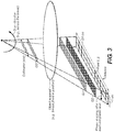
- a perspective view of a slot-scanning phase-contrast digital imaging system 100 can be used for mammography.
- the system 100 can include a conventional x-ray tube 110 for mammography imaging, a beam shaping assembly 120 comprising a filter or a tunable monochromator B, a collimator C, and a source grating G0, an x-ray grating interferometer 130 comprising a phase grating G1 and an analyzer grating G2, and an x-ray detector 140.
- the filter or a tunable monochromator B can be positioned after the collimator C.
- the three gratings e.g., G0, G1, and G2
- An object 150 e.g., a breast
- a supporting plate 152 can be supported by a supporting plate 152 and is compressed by a compression paddle 154, which can be moved and adjusted (e.g., vertically).
- FIG. 2 is a functional block diagram that shows an exemplary embodiment of a slot-scanning phase-contrast imaging system.
- FIG. 2 shows a functional block diagram of the imaging system 100 used for mammography.
- the x-ray tube 110, the beam shaping assembly 120, the grating interferometer 130, and the detector 140 can move with a prescribed three-dimensional relationship to a radiation source.
- the x-ray tube 110, the beam shaping assembly 120, the grating interferometer 130, and the detector 140 can be attached to a swing arm 160.
- the swing arm 160 can pivot around an axis co-axial with the focal spot of the x-ray tube 110.
- the x-ray tube 110 can be mounted at an angle with respect to the horizontal arm extension to illuminate an area of interest.
- the x-ray beam can be collimated to a narrow fan covering the interferometer 130 (e.g., gratings) and the active area of the detector 140 (e.g., about 24-cm long and 1-cm wide) by the collimator C.
- the entrance beam of the x-ray tube 110 can be slightly wider than the detector 140 and/interferometer 130 in order to reduce detector motion artifacts resulting from the edge of the detector 140 not being perfectly aligned with the collimator C at all times during the scan of an object.
- FIG. 3 is a diagram that shows a sectional illustration of an exemplary embodiment of components of a slot-scanning phase-contrast digital mammography imaging system in accordance with the application.
- FIG. 4 is a diagram that shows a sectional illustration of another exemplary embodiment of components of a slot-scanning phase-contrast digital mammography imaging system in accordance with the application.
- One difference between the imaging system of FIG. 3 and the imaging system shown in FIG. 4 is that the orientation of the grating bars of the gratings (e.g., the three gratings G0, G1, and G2) in FIG. 4 are parallel to the scan direction of the swing arm 160 (e.g., the x-ray fan beam), instead of being perpendicular to the scan direction of the swing arm 160 in FIG. 3 .
- the x-ray source 110 can be a conventional x-ray source.
- the x-ray source 110 can be a polychromatic x-ray tube for mammography imaging.
- the x-ray source 110 can have a rotating anode made of tungsten (W), molybdenum (Mo), rhodium (Rh), or an alloy of heavy-element materials.
- the area of the focal spot can be between 0.01 mm 2 and 1.0 mm 2 .
- additional filtration can be optionally used to spectrally shape the x-ray beam into a narrow-bandwidth beam to reduce or eliminate the unnecessary soft x-rays that are mostly absorbed by the patient and contribute to the radiation dose received during the examination, and/or the hard x-rays that can reduce the quality of the image.
- Exemplary typical filter materials are aluminum (Al), molybdenum (Mo), rhodium (Rh), silver (Ag), and other metals.
- the filter B can be a tunable monochromatic x-ray filter that can be used with a divergent polychromatic x-ray source to produce monochromatic x-rays with a narrow spectrum centered at a selectable energy with a bandwidth of 1-3 keV.
- the imaging system 100 can include three gratings.
- the source grating G0 can have absorbing gold bars
- the phase grating G1 can be made of silicon
- the analyzer grating G2 can be made of absorbing gold bars.
- the source grating G0 can be placed close to the x-ray source 110.
- the second grating G1 and the third grating G2 can have a fixed distance in between, for example, by being mechanically coupled together, electromechanically connected or rigidly coupled together.
- the source grating G0 and the interferometer 130 can be coupled to have a variable, but known distance therebetween.
- the source grating G0 can allow the use of a large incoherent x-ray source as the x-ray source 110 because the source grating G0 can create an array of individual line sources that each can provide sufficient spatial coherence for the interferometric contrast.
- the images created by the source grating G0 generated line sources can be superimposed congruently in the detector plane at the detector 140 leading to a gain in intensity (e.g., controllable interference).
- the phase grating G1 can operate as a beam splitter and divide the incoming beam essentially into the ⁇ 1 diffraction orders. These two ⁇ 1 diffracted beams can interfere and form a periodic interference pattern in the plane of the second grating G2 through the Talbot self-imaging effect.
- an analyzer second grating G2 can be placed at a specific Talbot distance from the phase first gating G1 to enable the transform of fringe positions into intensity modulations on the detector 140 located directly behind the second grating G2 with the phase stepping technique.
- the size the source grating G0 can be small (e.g., about 1 cm x 0.5 cm) because of the small angle subtended by the x-ray fan.
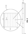
- the FOV can be 24 cm x 30 cm. Since the object is located close to the interferometer formed by gratings G1 and G2, the size of these gratings should match the FOV. Given the state of art for standard photolithography techniques, repeatable fabrications of such large-area gratings G1 and G2 (e.g., 24 cm x 30 cm) with high or sufficient yield and an acceptable uniformity are not trivial.
- a standard 6 or 8 inch-silicon wafer can be used to fabricate multiple small gratings (e.g., each with an area of 8 cm x 1 cm) within a square of 8 cm x 8 cm.
- a long and narrow grating e.g., 24 cm x 1 cm
- FIG. 5 is a diagram that shows an embodiment of a long and narrow grating (e.g., formed by abutting two or more small gratings together) according to the application.
- a long and narrow grating e.g., formed by abutting two or more small gratings together
- one embodiment of the G1 grating or G2 grating can be formed using a standard silicon wafer.
- a standard 8" wafer can be used to provide the long and narrow gratings G1 and G2.
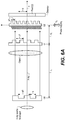
- FIG. 6A is a diagram that shows a schematic of an exemplary three-grating phase contrast imaging system (e.g., interferometer).
- three gratings namely, the source grating G0 having absorbing gold bars, phase grating (or beam splitter) G1 made of silicon, and analyzer grating G2 having absorbing gold bars are used.
- the gratings are made from silicon wafers using standard photolithography techniques, and subsequently electroplating to fill the grooves with gold (GO and G2).
- the interferometer is formed by G1 and G2. The plane and the grating bars of these three gratings are parallel to each other.
- the source grating G0 allows the use of large incoherent x-ray sources since it creates an array of individual line sources each providing enough spatial coherence for the interferometric contrast.
- the images created by each line source are superimposed congruently in the detector plane leading to a gain in intensity.
- the phase grating G1 acts as a beam splitter and divides the incoming beam essentially into two first diffraction orders that interfere and form periodic fringe patterns in planes perpendicular to the optical axis (z). Based on the Talbot effect, the periodic fringe pattern, which is called the self image of the phase grating G1, will have its highest contrast at the first Talbot distance d 1 behind G1.
- the period of the fringe pattern (p 2 ) at the plane of the analyzer grating G2 placed at a distance of d 1 from G1 is approximately half the period of G1.
- the analyzer grating G2 has approximately the same period of the fringe pattern (p 2 ).
- the incoming x-ray wavefront can be locally distorted by the object.
- the fringes formed by the phase grating G1 are displaced from their unperturbed positions.
- the fringe displacements are transformed into intensity variations by the analyzer grating G2 placed at a distance d 1 from the phase grating G1. This allows the use of an x-ray detector placed just behind the analyzer grating G2 with much larger pixels than the spacing of the fringes.
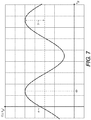
- FIG. 7 is a diagram that shows intensity variation for one detector pixel (i, j) when one of the gratings (e.g., G2) is scanned along x g and the corresponding Fourier series coefficients a, b, and ⁇ .
- the phase ⁇ of the oscillation in each pixel is a measure of the wavefront phase gradient, while the average detector signal a in each pixel over the grating scan is equivalent to the conventional absorption image.
- the total phase shift of the object can thus be retrieved by a single one-dimensional integration along the direction x.
- FIG. 6B is a diagram that shows a schematic of another exemplary three-grating phase contrast imaging system.
- a three-grating PCI system can include stationary G0, G1, and G2 gratings and an object to be imaged can be moved (e.g., across) relative to the stationary G0, G1, and G2 gratings.
- F is optional additional filtration
- C is an optional collimator or beam shaping apparatus.
- An indirect flat panel detector can include a layer of scintillator made of CsI, Gd 2 O 2 S, or other scintillating phosphors coupled with an array of photodiodes (e.g., a-Si photodiodes) and switches (e.g., thin-film transistor (TFT) switches).
- the thickness of the scintillator layer can be between 80 um and 600 um.
- the pixel pitch of the detector is ranged from 20 to 200 um.
- a direct detector can include a photoconductor such as amorphous selenium (a-Se) or PbI 2 to produce electrical charges on the detection of an x-ray.
- a-Se amorphous selenium
- PbI 2 amorphous selenium
- a charge-coupled device (CCD) based x-ray detector can be used as the detector 140.
- the CCD based x-ray detector can include a scintillating screen.
- a tiled CCD detector array operated in time delay integration (TDI) mode is preferred to enable continuous scanning motion and x-ray illumination during each scan.
- the detector array can be formed by tiling two or more CCD devices together and can be coupled to a scintillator layer and a fiber optic plate (FOP).
- the FOP is used to protect the CCD array from radiation damage.
- a slot-scanning system with a beam width comparable to the pixel width would require an extremely high tube output.
- the TDI operating mode of the CCD can allow a significantly wider beam to be used.
- the detected x-rays are first transformed into light photons via the scintillator layer.
- the light photons are then transmitted to the CCD through the FOP producing electrons in the CCD in response to the light emission from the scintillator upon x-ray absorption.
- the TDI mode can enable x-ray integration across the CCD width while maintaining the pixel resolution.
- the detector array can include four CCDs, each having a size of 6 cm x 1 cm, abutted along their narrow dimension to form a long and narrow detector (e.g., 24 cm x 1 cm).
- the typical pixel size is between 20 um and 200 um.
- a linear photon counting gaseous detector using avalanche amplification process can be also used as the detector 140.
- crystalline Si, CdTe, and CdZnTe can also be used in direct-conversion photon-counting detectors.
- This exemplary single photon counting detection technique can discriminate noise in the detector 140 from a true x-ray photon interaction. By counting signals above a predefined threshold, an electronic noise free and efficient counting of single x-ray photons is achieved.
- this detector type is used in a slot-scanning system according to embodiments of the application, significant reduction of patient dose and scattered radiation and/or a considerable increase in image quality in terms of contrast and spatial resolution can be obtained, as compared to the integrating detectors (such as direct and indirect flat-panel detectors and CCD devices).
- grating parameters and the geometric system parameters in exemplary embodiments can be restricted by the choice of x-ray source, the limitation of the grating fabrication process, the practicality of the system size, the system performance requirements, and the conformation of physical laws.
- the system parameters and grating parameters should satisfy the following equations.
- the structure height of the silicon phase grating G1 has to be such that the x-rays passing through the grating bars undergo a prescribed phase shift or a phase shift of ⁇ (as an example), which results in the splitting of the beam into the ⁇ 1 diffraction orders.
- h 1 ⁇ 2 ⁇ Si
- the structure height of gratings G0 and G2 should be large enough to provide sufficient absorption of x-ray (e.g., > 75%) for selected or optimum system performance.
- n By first selecting n, p 2 , ⁇ , and L based on system requirements and limitations on grating fabrication, other parameters, namely, s, p 0 , p 1 , h 1 , h 2 , h 3 , and d n can then be determined.
- Table 1 lists exemplary system design parameters and grating parameters for an embodiment of a slot-scanning phase-contrast digital mammography system.
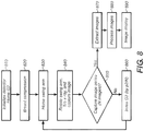
- FIG. 8 is a flow chart that shows an embodiment of a method for operating a slot-scanning phase-contrast digital imaging system.
- the exemplary method embodiment of FIG. 8 will be described using and can be implemented by the system embodiment shown in FIG. 1 and FIG. 3 , however the method is not intended to be so limited.
- the detector is initialized in preparation for exposure and the analyzer grating G2 is moved to a prescribed position or home position (operation block 810). Then, for mammographic medical images, the breast can be compressed (e.g., to improve image quality) (operation block 820).
- the swing arm 160 is set to an initial or home position (operation block 830).
- block 830 can position the x-ray tube 110, the beam shaping assembly 120, the x-ray grating interferometer 130 and the x-ray detector 140 that can be rigidly mounted to the swing arm 160.
- the x-ray beam can be scanned across the object as the swing arm 160 rotates in an arc like a pendulum covering the width of the object (e.g., about 30 cm) as shown in FIG. 3 .
- the image data recorded by the detector 140 can be read out and stored in a memory unit of a computer (e.g., at the slot-scanning phase-contrast digital imaging system or at a wirelessly coupled control console having a processor, display and memory.
- the detector is a long and narrow CCD based detector and can operate in the time delay integration (TDI) mode for signal detection.
- TDI time delay integration
- the analyzer grating G2 e.g., mounted on a piezo translation stage
- the analyzer grating G2 is then moved laterally by a predetermined distance (step) before the next scan of the x-ray beam starts (operation block 860) and the process jumps back to block 830 where the swing arm 160 is returned to the initial pre-scan position or home position (or reversed in rotational direction) to be ready for the next scan in the image series.
- the image data set can be extracted, processed, and displayed on a monitor (operation blocks 870, 880, 890).
- N e.g., typically 5 to 8
- the same image data set can be processed by an image processing unit of the computer to construct multiple images of the object including absorption contrast, differential phase contrast, phase shift contrast, and dark-field images, as described herein.
- Exemplary alternate phase stepping implementations include but are not limited to: (i) moving grating G1 (instead of G2) in the direction perpendicular to both the optical axis and the grating bars of G1; (ii) rotating G1 and G2 together around an axis along the orientation of grating bars by an angle (e.g., the two gratings are kept in an aligned position with respect to each other or are fixed together mechanically); or (iii) moving the x-ray source in the direction perpendicular to both the optical axis and the grating bars of the gratings.
- These exemplary alternate phase stepping implementations can be implemented on the exemplary swing arm 160 configuration shown in FIG. 3 .
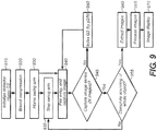
- FIG. 9 is a flow chart that shows an embodiment of a method for operating a slot-scanning phase-contrast digital imaging system.
- the exemplary method embodiment of FIG. 9 will be described using and can be implemented by the system embodiment shown in FIG. 1 and FIGS. 3-4 , however the method is not intended to be so limited.
- Fig. 9 shows another "step-dither-step" mode of system operations where the swing arm can scan across the object in a step-wise motion. The distance of each step can be about the width of the detector.
- a series of x-ray exposure/image capture operations can be performed (e.g., N images captured) using the aforementioned phase stepping technique (e.g., move the analyzer grating G2 by p 2 /N).
- the swing arm moves to the next step position and another series of x-ray exposure/image capture operations is performed until the swing arm steps through and completes the whole object scan.
- the raw image data set is extracted, processed, and displayed on a monitor.
- the raw images data subset can be extracted at the end of each "step", and the captured raw images can be processed and displayed on a monitor concurrently or at the completion of the last step.
- the detector is initialized in preparation for exposure and the analyzer grating G2 is moved to a prescribed position or home position (operation block 910). Then, an object can be positioned or for mammographic medical images, the breast can be compressed (e.g., to improve image quality) (operation block 920).
- the swing arm 160 is set to an initial or home position (operation block 930).
- the swing arm 160 is stepped to a current step position (operation block 933), the x-ray beam is fired to expose and capture an image of a portion of the object (operation block 940). Then, it is determined whether the image series is complete for that step (e.g., N images have been captured) in operation block 945.
- the image data set can be stored and it can be determined in operation block 955 whether scanning is complete for the whole object.
- N e.g., typically 5 to 8
- the swing arm 160 is stepped to the next position (operation block 933) and operation blocks 940, 945 and 950 can be repeated.
- the image data set can be extracted, processed, and displayed on a monitor (operation blocks 960, 965, 970).
- the same image data set can be processed by an image processing unit of the computer to construct multiple images of the object including absorption contrast, differential phase contrast, phase shift contrast, and dark-field images, as described herein.
- ⁇ x y ⁇ 2 ⁇ ⁇ ⁇ ⁇ x y ⁇ x
- the fringe displacements are transformed into intensity values by an analyzer grating G2 placed at a distance d n from the phase grating G1.
- a two-dimensional detector with much larger pixels than the spacing of the fringes can be used to record the signal. Scanning the lateral position x g of one of the gratings (e.g., the analyzer grating G2) causes the recorded signal in each pixel to oscillate as a function of x g .
- the signal oscillation curve can be expressed by a Fourier series, I s i j x g ⁇ a s i j + b s i j cos 2 ⁇ ⁇ p 2 x g + ⁇ s i j (with the object) I b i j x g ⁇ a b i j + b b i j cos 2 ⁇ ⁇ p 2 x g + ⁇ b i j (without the object)
- a dark-field image is formed from higher-angle diffraction intensities scattered by the object.
- the information about the scattering power of the object is contained in the first Fourier amplitude coefficient, bs(i, j) of Is(i, j, x g ).
- These four different images of the object can be derived from the same data set and can be complementary to each other to provide multiple information of the object enabling the visualization of subtle details in the object.
- Embodiments of phase-contrast digital imaging systems and/or methods of using the same can provide various advantages according to the application.
- Embodiments of slot-scanning grating-based differential phase contrast systems and/or methods can significantly enhance the contrast of low absorbing tissues (e.g., the contrast between healthy and diseased tissues), which can be especially useful for mammography and orthopedic joints.
- Embodiments of slot-scanning grating-based differential phase contrast systems and/or methods can allow the use of small gratings and detectors to produce a large-area image.
- Embodiments can provide reduction in motion blur, scattered radiation, and patient dose without using a grid.
- Embodiments of slot-scanning grating-based differential phase contrast systems and/or methods can use curved gratings and detectors circularly around the source focus to enable the design of a more compact system and reduce or eliminate the shadowing effect of the phase grating and/or the scan effect of the analyzer grating occurred in the edge regions of the image.
- Certain exemplary embodiments for slot-scanning phase-contrast digital imaging systems and/or methods for using the same can employ step-dither-step approaches, where one of the gratings, either phase grating G1 or analyzer grating G2, can be stepped with respect to another.
- one of the gratings either phase grating G1 or analyzer grating G2
- N is a number of steps (e.g., using a piezo translational stage) required to cover a period of grating G2
- the lateral size of the grating G2 is l G2
- the scan of an object with lateral size S can use or require S / l G2 ⁇ N of x-ray exposures.
- Both exemplary scanning embodiments described in Figures 8 and 9 have either the swing arm or the analyzer grating G2 return back to its initial (e.g., home) position after one slice of the object is scanned.
- precision positioning of these devices e.g., translational piezo drivers
- the multiple forward-backward types of motions can add up to significant spatial errors after the whole object scan is complete.
- continuous motion of the swing arm with minimal or no stepping of the analyzer grating is preferable. It is also preferable when the relative position of the gratings G1 and G2 does not change (e.g., no stepping) and/or the swing arm continuously moves across the object, which can reduce a scanning time.
- a detuned phase contrast imaging system can be understood to be an imaging system in which the pitch p 2 of the analyzer grating G2 is purposely controlled or fabricated to be unequal to a period of interference pattern p int at a Talbot distance behind the phase grating G1.
- a detuned phase contrast imaging system can be understood to be an imaging system in which the pitch p 2 of the analyzer grating G2 is controlled or fabricated to be equal to a period of interference pattern p int at a Talbot distance behind the phase grating G1, but the analyzer grating G2 is positioned away from the corresponding Talbot distance.
- a detuned phase contrast imaging system can generate a periodic fringe pattern, where the fringe pattern occurs over a width or a portion of the width of the analyzer gating G2.
- FIG. 11 is a diagram that illustrates concepts of exemplary tuned and detuned phase contrast imaging systems.
- Exemplary values of f 0 in indirect charge integrating detectors can be typically between 1 and 2 cyc/mm, while value of f 0 can reach 5 cyc/mm in the case of direct photon counting detectors. That said, the detector will measure no signal at 1000 cyc/mm.
- the only detectable signal is: MTF f ⁇ cos 2 ⁇ f int ⁇ f 2 x / 2
- the signal is increased or maximum.
- the detector yields the uniform image.
- Figure 12 is a diagram that illustrates examples of the open field images measured in the detector plane for tuned and detuned configurations of a phase contrast imaging system embodiment.
- an open field image for a tuned phase contrast imaging system embodiment can produce an unchanging or flat open field image across the analyzer grating G2.
- the lateral size of an image is chosen to be equal to one period of fringe pattern as an example.
- the phase contrast imaging system, ⁇ f can be ⁇ 5%, ⁇ 1% or ⁇ 0.1%.
- FIG. 13A shows several MTFs plotted for different alpha slope (e.g., see equation 16).
- the MTF with a higher value of slope can have a longer plateau (e.g., slower reduction) for a spatial frequency below the half value frequency.
- the higher slope is typical for a detector with a better frequency response, for example direct conversion photon-counting detector in comparison to indirect detector.
- the slope ⁇ is typically close to 1 and higher, while the half value frequency is in the range between 1.5 and 2 cyc/mm.
- FIG. 13B shows the percentage of the contrast drop as a function of MTF slope ⁇ and spatial frequency f 0 .
- the drop in contrast relative to the maximum possible is less for smaller ⁇ f .
- the curves shown in Figure 13 get even lower for higher f 0 (e.g., for a detector with higher quantum efficiency).
- Higher MTF slope ⁇ can further reduce the drop in contrast.
- the MTF slope ⁇ is typically close to 1 and higher.
- embodiments of detuned system can only be implemented according to schematics shown in Figure 3 .
- the fringe patters in the detector plane has to be oriented such that the arms swings laterally across the pattern.
- PCI implementation depicted on Figure 4 is suitable for tuned phase contrast imaging system, it cannot be applied to detuned PCI system.
- the analyzer grating G2 and the detector D can be moved together (e.g., using an attached translational piezo driver) to simultaneously move them in the direction of the x-ray beam (e.g., z axis) such that the frequency ( ⁇ f ) of fringe pattern in the detector plane can be adjusted.
- the phase contrast imaging system can be tweaked by shifting the analyzer grating G2 along the beam axis (e.g., axis z ) relative to the phase grating G1.
- the analyzer grating G2 can peak at different z position of the interference pattern formed by phase grating G1.
- the different frequency of interference pattern, f int is used to form the desired fringe pattern at the detector plane.
- the phase retrieval algorithm can require multiple x-ray exposures at different lateral positions of analyzer grating, which allows forming a cosine shaped intensity curve shown in Figure 7 .
- the detector can already measure the cosine shaped fringe pattern and the grating stepping is no longer required.
- the grating G1, the grating G2 and the detector D can be fixed at one relative position and moved to image the object, for example attached to a swing arm, and the swing arm can be continuously moved across the stationary object.
- the swing arm can be at rest and the object can be laterally moved across in the plane perpendicular to incident x-rays.
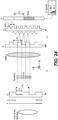
- Figure 14 is a diagram that illustrates exemplary motion of interferometer with respect to objects or vise versa for a phase contrast imaging system embodiment.
- Figure 15 is a diagram that illustrates exemplary of object scan schematics that project individual slices of the object onto one-period fringe pattern measured in the detector plane.
- Triangle, circle, and square shapes shown in Figures 14-15 refer to different parts of the exemplary object.
- each individual part of the object such as triangle, circle and square
- N 8
- each of the exemplary shapes e.g., triangle, circle, and square
- Figure 16 shows the schematics of intensity curve formation for an individual slice of the object (e.g., triangles, circles, and squares).
- the Fourier based reconstruction technique described herein, can be applied to each of the intensity curves to form the transmission, differential phase, and dark-field images for each of the slices. Then the slice images can be combined or stitched together to form image(s) of the full object.
- Embodiments of a grating-based differential phase contrast digital imaging systems are related to a slot scanning grating based PCI system that is detuned to use a continuous motion of the swing arm with the interferometer setup (e.g., phase grating G1, analyzer grating G2, and detector D) fixed to an arm for a moment of the swing motion.
- Embodiments of DR PCI imaging systems and/or methods can adjust the energy of the incident photon beam (e.g., different kVp values, exposure levels, and/or filters) based on the thickness of the object or breast.
- a DR PCI system can have multiple G1 gratings with the same pitch, but different heights of Si structure that are selected for the corresponding mean photon energy preferably such that the phase shift created by the respective G1 grating provides desired or maximum contrast (e.g., ⁇ phase shift).
- embodiments of DR PCI systems and/or methods can use continuous motion of the swing arm to scan an object with FOV larger then the size of detector.
- geometrical parameters of the gratings are set such that the interference system (i.e. G1 + G2 + D) is detuned (e.g., produces a fringe pattern in the plane of detector) for embodiments of DR PCI systems and/or methods.
- phase stepping e.g., relative to grating G1, G2, or G0 motions during the scan
- phase stepping are not invoked.
- Embodiments of DR PCI systems and/or methods can use different energy of the photon beam and/or different exposure levels (e.g., depending on the breast thickness). For example, multiple different exposure levels or three kVp settings can be used (e.g., 25, 30, and 40 kVp) where each of kVp settings can require its own phase grating (e.g., three different phase gratings can be replaceably mounted on a low absorbing holder disposed in the phase grating G1 plane).
- each of phase gratings e.g., G1 can have same pitch but different height of phase shifting Si structure because the phase shift is energy dependent.
- the G1 grating holder can correspondingly be exchanged to another grating holder to match the mean energies of the new spectra (e.g., Si structure heights).
- the imaginary part ⁇ contributes to the attenuation of the amplitude and the real part ⁇ (refraction index decrement) is responsible for the phase shift.
- the refractive index can be expressed in terms of the atomic scattering factors f 1 and f 2 : n ⁇ 1 ⁇ r e N a ⁇ 2 ⁇ 2 ⁇ ⁇ ⁇ k x k f 1 , k + if 2 , k / ⁇ k x k A k , where r e , N a , ⁇ , and ⁇ are the electron radius, Avogadro number, photon wavelength, and effective density of compound, respectively.
- the summation is taken over the relative concentrations x k of each of the chemical elements of atomic mass A k comprising the compound.
- Figure 17 shows the linear attenuation and phase shift per unit of length (e.g., 1 cm) for materials that are and can be common for a breast: adipose tissue, glandular tissue, skin, and 20% hydroxyapatite water-based mixture (e.g., which can represent a calcification). As shown in Figure 17 , the phase shift is significantly (e.g., few orders) higher then the absorption.
- Figure 18 shows an example of the contrast between two materials, glandular tissue and skin, that have very similar attenuation curves and that can be virtually inseparable in standard absorption image.
- the difference between material linear attenuations can be plotted on the left, while the difference in phase can be shown on the right.
- the curve for phase shift is significantly higher than the one for absorption, and therefore the image of the material phase shift should provide a better material differentiation.
- the absorption and phase shift curves from Figure 17 are tabulated in Table 2 for photon energies 20, 30, and 40 keV. Additionally, the exemplary two-material absorption and phase shift differences from Figure 18 are shown in Table 3.
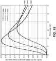
- FIG. 19 shows the glandular to adipose signal to noise ratio for different thicknesses of compressed breast as a function of photon energy. Curves with triangles 1902, stars 1904, and circles 1906 correspond to 3, 5, and 8 cm breast thicknesses, respectively.
- the signal to noise ratio is estimated between two pixels, where one of the pixels contains an x-ray projection from the adipose tissue and another pixel correspond to projection from glandular tissue.
- the thicknesses of the tissues in the example are equal.
- a desired photon energy or optimal photon energy located at the peak's maximum
- a high or maximum SNR for 3 cm breast thickness can occur about 18 keV photon energy
- a high or maximum SNR for 8 cm breast thickness can occur about 26 keV photon energy.
- the curves 1902, 1904, 1906 were calculated with assumption that pixels contain pure glandular and pure adipose tissues.
- the desired parameters can change.
- the desired or optimal energies can change from 18.3 to 19.5 keV for 3 cm thick breast, from 21.8 to 23.4 keV for 5 cm thick breast, and from 25.8 to 27.7 keV for 8 cm thick breast. In such a case, desired or optimal energy settings drift towards higher energies for thicker breast.
- 25, 30, and 40 kVp x-ray spectra can be chosen for imaging thin, medium and thick breasts, respectively.
- the mean energies of the chosen x-ray spectra are 21.7, 23.3, and 28 keV, respectively, which can correspond to the deducted earlier energy values.
- imaging parameters can further be adjusted to meet, for example, signal to noise performance parameters.
- geometry of the PCI system is a function of the x-ray energy.
- the mean energy of the x-ray beam is changed, e.g., the spectrum is altered; embodiments herein can change distances between G0 grating and G1 (e.g., L) and between G1 and G2 (e.g., d).
- Exemplary DR PCI system parameters for different voltage settings on the x-ray tube are described in Table 4.
- phase grating structure which can be made of Si for other materials known to one skilled in the art
- the array of three phase gratings can be used.
- the array of gratings can have the same pitch as shown in FIGS. 20(a)-20(b) .
- Exemplary multiple phase gratings G1 can be attached to a holder (e.g., ladder) made of low absorbing material.
- exemplary heights for the three G1 gratings can be chosen so that the incident x-rays preferably undergo the phase shift of ⁇ .
- a separate, coupled or integral translation stage can be attached to a holder for moving an array of multiple phase gratings G1 (e.g., in the x direction).
- an appropriate tube voltage can be selected and the corresponding G1 grating can be placed in line with the interferometer setup, as shown in Figure 21.
- Figure 21 shows schematics of an array of gratings G1 phase disposed in front of a single grating G2 and a single detector D.
- a translation stage 2120 can move the array of gratings G1 and/or an optional holder 2110 in a prescribed 3D motion such as the x direction for swapping between the multiple phase gratings G1.
- an etching process of the grating shown in Fig. 20(a) may be difficult because such a configuration of gratings can require three independent etching processes.
- an the initial height of the Si layer and the deepness of a recess e.g., etch
- a recess e.g., etch
- a single etching mask can be used.
- an alternative multiple gratings G1 embodiment can use a single Si ladder, which can be split on two or more parts, where each of the parts can be individually etched to form the trenches of substantially consistent respective deepness.
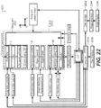
- Fig. 22 is a functional block diagram that shows an embodiment of an adjustable DR PCI system capable of imaging different mean energies of a radiation source.
- a computer or other type of dedicated logic processor for obtaining, processing, and storing image data is part of the DR PCI system, along with one or more displays for viewing image results.
- a computer-accessible memory is also provided, which may be a non-volatile memory storage device used for longer term storage, such as a device using magnetic, optical, or other data storage media.
- the computer-accessible memory can comprise an electronic memory such as a random access memory (RAM) that is used as volatile memory for shorter term data storage, such as memory used as a workspace for operating upon data or used in conjunction with a display device for temporarily storing image content as a display buffer, or memory that is employed to store a computer program having instructions for controlling one or more computers to practice method and/or system embodiments according to the application.
- RAM random access memory
- a PCI imaging system can include or be coupled to a computer 2210.
- a swing arm rotation motor can be attached to a swing arm 2220 that can mount or hold x-ray unit (I) and interferometer unit (III).
- the x-ray unit (I) can include x-ray tube, filter, collimator, and source grating G0, while the interferometer unit (III) can include phase grating G1, analyzer grating G2, and detector D.
- the object can be positioned at or placed in unit (II), which can include a compression paddle and support plate for mammography or the like.
- All three units (I, II, and III) can be positioned by a support structure such as placed inside a C-arm 2220.
- the unit II can have a controlled or rigid connection to the C-arm, while the swing arm 2222 can move the x-ray unit I and the interferometer III relative to the unit II.
- the C-arm 2220 can be rotated such that different exemplary projections of the breast (e.g., Cranio-caudal (CC) and Mediolateral Oblique (MLO)) can be taken.
- the breast thickness can be measured by a breast thickness measurement unit.
- a look-up table can be used to download a corresponding PCI geometry, and translation stages 1, 2, and 3 provide necessary changes to implement the corresponding PCI geometry based on the LUT output.
- Translation stage 1 can swap the phase gratings G1 based on the x-ray spectrum used for imaging.
- Translation stage 2 can adjust relative position of the analyzer grating G2 and the detector D to the phase grating G1.
- the analyzer grating G2 and the detector D can be rigidly connected together or can have an additional translation stage that can adjust the distance between them.
- Translation stage 3 can move the interferometer unit (III) along the axis of beam propagation (e.g., z -axis).
- a user interface 2230 can allow the operator to control the PCI system 2200 using the computer 2210.
- the user interface 2230 can include the capability to set parameters for examination procedures.
- An x-ray tube controller connected to a computer 2210, can control emission by the x-ray tube synchronous to the motion of the swing arm 2222.
- Raw data (or processed data) output by the detector D) can be stored in a data storage unit 2242, then processed by image processor 2244, and then displayed as images to operator on display 2246.
- anode and filter selector unit 2250 can change the anode material and filter, for example from tungsten (W) to molybdenum (Mo) anode and from Aluminum (Al) filter to Mo or Rubidium (Rd).
- the anode material and/or the filter material can be included in the LUT.
- the DR PCI system can be automatically adjusted for different mean energies of an x-ray source responsive to a determination of a thickness and/or examination procedure for a series of one or more diagnostic exposures. Accordingly, once the object thickness is input for the DR PCI system, a configuration including at least phase grating selection, a first distance between the phase grating and the detector and a second distance between the phase grating and the source grating can be automatically adjusted. Then, an exposure can be initiated by the operator or automatically once the DR PCI system geometry and/or configuration corresponds to the object thickness.
- FIG. 23 is a flow chart that shows an embodiment of a method for operating a slot-scanning phase-contrast digital imaging system.
- the exemplary method embodiment of FIG. 23 will be described with reference to and can be implemented by the system embodiment shown in FIGS. 10A-10C , however the method is not intended to be so limited.
- an initialization can be performed (operation block 2310).
- An exemplary initialization can include initializing the detector in preparation for exposure. Then, the C-arm is moved into a position of a desired projection (e.g., CC or MLO). Further, the breast is compressed, which is necessary for mammographic medical imaging, and the breast thickness is measured. Depending on the breast thickness an appropriate PCI configuration can be determined (operation block 2320). In one embodiment, the PCI configuration can be read-out from look-up table (LUT). Responsive to the PCI configuration, the translation stage 1 can move the appropriate phase grating G1 into position, e.g., centered on the x-ray trajectory that connects G0, G1, and D.
- LUT look-up table
- the translation stage 2 can set the distance d between G2 and D equal to the first Talbot distance, and the distance L between G0 and G1 can be adjusted by translation stage 3.
- the appropriate kVp and mAs values are loaded into x-ray tube controller.
- the swing arm is set into "neutral" position, for example, the swing arm can be vertically aligned within the C-arm (operation block 2330).
- Operation block 2340 can include setting the swing arm to an initial (home) position. In such a position, at least a portion to the majority part of the object is outside of C-arm's field of view (FOV). In one embodiment, no overlap, or a slight overlap with the object can be set in the C-arm's initial FOV. Then, the arm continuously moves across the object with the x-ray tube firing synchronically with the motion of the arm, and the detector can integrate, export and/or store the corresponding image data.
- the number of synchronous x-ray exposures can depend on the lateral size of the object and the number of data points N in one object slice, desired or needed for image reconstruction (operation block 2350, no). For example, a size of one object slice can be equal to the width of fringe pattern or detector.
- image processing and/or display can be performed (operation block 2360).
- Image processing can include accessing data recorded by the detector (e.g., stored in a memory unit of a computer). Further, the data can be rearranged to form the intensity curves for each of the object slices. Then, the Fourier based reconstruction procedure can be applied. As a result, absorption, differential phase, and dark field images can be determined and/or displayed. Also, the differential phase image can be integrated and the phase shift image can be additionally presented to an operator.
- digital radiographic (DR) phase-contrast imaging (PCI) systems can include multiple phase gratings G1 that can be made from different or multiple materials.
- the multiple phase gratings G1 can be different materials, which each correspond to a different anode material for a switchable x-ray source (e.g., W or Mo).
- the multiple phase gratings G1 can be different materials based on additional characteristics such as etchability or cost.
- multiple pairs of gratings G1 and G2, or sets of gratings G0, G1, G2 can be switched for different x-ray imaging parameters such as but not limited to kVp setting, mean beam energy, object size, examination type or combinations thereof.
- a first pair of gratings G1a, G2a could be switched to a second pair of gratings G1b, G2b.
- a first set of gratings G0c, G1c, G2c can be switched to a second set of gratings G0d, G1d, G2d based on an object thickness or other imaging parameter.
- digital radiographic (DR) phase-contrast imaging (PCI) systems can include multiple phase gratings G1 that can be modify a frequency of the period of the interference pattern generated thereby (e.g., at a position of the analyzer grating G2).
- multiple gratings G1 can each have a different respective pitch.
- a set of multiple phase gratings G1 could generate respective interference patterns at relative periods of 1x, 2x and 2.5x to interact with one or more analyzer gratings G2.
- Embodiments of phase contrast imaging systems and/or methods can address or simplify the problem of material decomposition by adding the phase shift image, where contrast between materials is much greater than a contrast available in the absorption image. Although, having the phase and absorption information can significantly help in material differentiation, the discrimination between multiple materials (e.g., especially more than two) can still be difficult. Embodiments of phase contrast imaging systems and/or methods can combine spectral imaging with phase contrast imaging to allow increased material identification.
- Certain exemplary embodiments can use photon-counting energy-resolving detector (e.g., CZT detector) for spectral phase contrast imaging.
- energy-resolving detector e.g., CZT detector
- embodiments described herein can get spectral information including but not limited to 1) three images (e.g., absorption, differential phase contrast, dark-field) for first energy bin and 2) another three images for second energy bin.
- the analyzer G2 grating has to be placed at a Talbot distance (e.g., the first Talbot distance).
- Talbot distances are energy dependent.
- different mean energy in each of multiple x-ray beams will create or use different Talbot distances.
- the detector or the analyzer G2 grating-detector combination should be placed at two different positions.
- Embodiments of digital radiographic phase contrast imaging systems and/or methods can provide separate data/images for at least two energies using an energy resolving detector and analyzer grating at a single position during using a single scan (e.g., series of exposure(s)) of an object. Further, embodiments of digital radiographic phase contrast imaging systems and/or methods can provide two different energy exposures of an object to obtain diagnostically acceptable SNR data/images for each of the two different energy exposures without modifying a DR PCI configuration. Certain exemplary embodiments of digital radiographic phase contrast imaging systems and/or methods can implement a tuned or de-tuned arrangement of an x-ray interferometer.
- FIG. 24 is a diagram that shows an embodiment of a grating -based phase contrast imaging system using an energy-resolving detector.
- an embodiment of a grating-based phase contrast imaging system can include a three-grating (G0, G1, G2) Talbot-Lau interferometer setup and an energy-resolving detector (e.g., photon-counting) 2410 placed behind an analyzer G2 grating.
- an energy comparator in an imaging array or pixel of a detector e.g., pulse height analysis
- Two exemplary system and/or method embodiments to implement dual energy or spectral imaging in phase contrast imaging respectively include a first embodiment using two x-ray exposures at different exposures (e.g., kVp values) and a second embodiment including only one x-ray exposure while using (at least) a two-bin energy-resolving detector.
- phase contrast imaging for the second embodiment is performed using two energies from a single exposure (x-ray exposure).
- the energy-resolving detector can be placed at one position only and the phase contrast imaging system can be tuned to acquire spectral images at two selected or optimized contrasts.
- a conventional (e.g., indirect or direct detection) flat panel detector e.g., area (e.g., 24x30)
- a single energy photon-counting detector can be used.
- Exemplary DR PCI systems can include multiple translation stages that can, individually or in combination, change: a) distance L between multi-slit grating (source grating G0) and phase grating G1; b) distance d between gratings G1 and G2 (e.g., typically set at 1-st Talbot distance); and/or c) selection among multiple G1 gratings for positioning (e.g., in front of grating G2).
- the x-ray tube can be fired once for each examination.
- the kVp value can be changed and the PCI system geometry (e.g., L and d ) can be adjusted such that the measured image has an increased contrast or highest contrast.
- the phase shift or the height of silicon (Si) in the phase grating G1 can be such designed so that the passing x-ray experiences a phase shift of ⁇ .
- Exposures at different kVp values (e.g., dual values) can require an array of two G1 gratings that have the same pitch, but different height of Si structure.
- Both G1 gratings can be attached to a low absorbing holder (or ladder), which can be moved by translation stage to quickly place respective different G1 gratings into position for an appropriate x-ray spectrum.
- Table 5 shows example PCI system parameters that can be used for dual energy imaging at 30 kVp and 40 kVp x-ray spectra, respectively.
- object motion or misalignment in the two scans can cause various disadvantages and can complicate material decomposition (e.g., motion artifacts).
- Various advantages can result from using one exposure, while spectral information is still extracted.
- FIG. 25A shows the intensity of interference pattern (also called a Talbot quantum carpet) in XZ plane for a plane monochromatic wave, where the mean energy of the x-ray beam is 28 keV.
- a vertical axis represents the lateral dimension x scaled by the pitch of G1 grating, while a horizontal axis corresponds to the direction of wave propagation, z .
- Vertical lines 2512, 2514, 2516 represent Talbot distances, d 1 , d 2 , and d 3 .
- the Talbot quantum carpet is plotted up to a third Talbot distance, and the interference pattern of p 1 /2 period is repetitive for every order of Talbot distance.
- the maxima of the repetitive pattern can be stretched in the z direction and the maxima intensity is degraded for higher orders of Talbot distances.
- FIG. 25B shows the intensity of interference pattern (also called a Talbot quantum carpet) in XZ plane for a polyenergetic wave, where the spectrum generated is the 40 kVp spectrum.
- Vertical lines 2522, 2524, 2526 represent Talbot distances, d 1 , d 2 , and d 3 , but are no longer optimal for higher order Talbot distances.
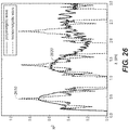
- FIG. 26 shows correlation factor R 2 as a function of wave propagation distance z . Dashed curve 2610 is the result for monoenergetic wave, and solid curve 2620 is the result for polyenergetic wave, where each curve includes three prominent peaks. As shown in FIG.
- maxima correspond to desired positions or the optimal positions, where the absorption grating G2 can be placed.
- FIGS. 25A-26 correspond to a single energy acquisition, where an energy resolving capability is not present and the detector would measure data in the entire energy spectrum.
- energy selectivity e.g., energy-resolving detector is used
- the quantum carpets can be estimated for each energy bin.
- FIG. 27 shows the quantum carpets for each of two energy bins of 40 kVp x-ray spectrum. In this case, previously wide blobs of interference pattern (see FIG. 25B ) spread out leaving a well defined areas of desired or optimal positions as shown in FIG. 27 .
- the selected or optimal positions on the quantum carpet significantly widen when going from monoenergetic to polyenergetic x-ray beam. Accordingly when the energy selectivity is invoked, the individual contribution from each energy bin causes redistribution of the optimal positions, as seen in FIG. 27 .
- FIG. 29 is a diagram that shows selected energy binning and x-ray spectrum according to certain exemplary embodiments that can achieve same Talbot distance for at least two or both energy bins.
- Certain exemplary embodiments herein can obtain such energy binning using additional filtration.
- FIG. 28 (right) optimization or selective energy binning was addressed by adding additional Tin (Sn) filtration, which can effectively transform one-peak spectrum into two-peak spectrum because of the kedge of the tin (see also FIG. 30 ).
- Sn Tin
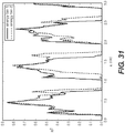
- the energy threshold between first and second bins was adjusted and an additional Al filtration was added such that the maxima of the first order Talbot peaks in the correlation graph are aligned as shown in FIG. 31 .
- FIG. 31 shows also, as shown in FIG.
- energy threshold and/or filtration can generate a spectrum split on two energy bins with approximately equal number of counts, respectively.
- Talbot distance By modifying the Talbot distance to be the same for both energy bins can allow an energy-resolving detector to be placed at a single position or at only one plane.
- the filtration was 6 mm of Al and 82 um of Sn, although embodiments are not intended to be so limited because other thicknesses and combinations of filters are contemplated and can be used as well as different multiple mean energies.
- embodiments can modify the energy threshold between 1 st energy bin and 2 nd energy bins.
- certain exemplary embodiments can modify originally one-peak x-ray spectrum to divide into at least two sub-peaks that can have concurrently aligned Talbot distances for energy bins corresponding to the sub-peaks. Further analysis (e.g. cross-correlation) can be conducted for other filtrations and energy thresholds to control or optimize for contrast.
- FIG. 32 is a diagram that shows a solid line spectrum 3210 that corresponds to the first exposure, and a dashed line spectrum 3220 that corresponds to the second exposure.
- the mean energies of the spectra 3210, 3220 can match the mean energies measured at each energy bin in the case of single exposure energy-selective mode (e.g., see FIG. 30 ).
- the PCI geometry can be fixed (e.g., L and d ).
- Gratings G0, G1, and G2 can be attached to a swing arm.
- the phase retrieval can be done either by employing phase stepping technique or by using PCI system in detuned mode, where relative positions of gratings are fixed and the continuous motion of the swing arm is employed.
- phase shift caused by the phase grating G1 is dependent on the shape of x-ray spectrum. Accordingly, a desired height of Si structure in phase grating G1 is energy dependent. For example, to get an increased contrast or maximum contrast, the x-ray wave (e.g., mean energy) should undergo a ⁇ phase at the phase grating G1. In one embodiment, when the energy-resolving detector is used and the PCI system fires the x-ray tube only once, a single phase grating G1 can be used. Below is the analysis of how the phase shift caused by Si structure is dependent on the shape of x-ray spectrum. FIG.
- FIG. 33A shows superimposed graphs of 40 kVp normalized x-ray spectrum with phase shift 3310 caused by the G1 grating Si structure (right axis)
- FIG. 33B shows superimposed graphs of the 40 kVp normalized x-ray spectrum with caused wave amplitude or phase contrast 3320 (right axis) caused by the phase shift.
- the dash-dotted line 3305 shown in FIGS. 33A-33B corresponds to the mean energy of the spectrum.
- the x-ray wave should undergo a ⁇ phase, which results in the splitting the beam into the ⁇ 1 diffraction orders (or wave amplitude of 2). As shown in FIG.
- FIG. 33A shows more than 3 ⁇ phase shift for the 40 kVp normalized x-ray spectrum. Every time when a ⁇ phase shift occurs, the amplitude 3320 of phase interference can show a change between maximum and minimum, as shown in FIG. 33B . Since photons that belong to the energy range where the wave amplitude is high or maximum can create improved or the best contrast, it is desirable to have an x-ray spectrum where the contribution to the low wave amplitude regions is reduced or minimal.
- the left edge or tale of the 40 kVp spectrum 3340 belongs to the non-optimal contrast region.
- the left edge of the spectrum 3340 can be shifted towards higher energies (e.g., by adding an additional filtration).
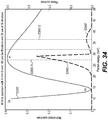
- FIG. 34 shows the 40 kVp normalized x-ray spectrum 3340' superimposed with the wave amplitude 3320 caused by the phase grating G1 phase shift.
- the case of two energy bins is shown in FIG. 34 where the dash-dotted lines 3350-1, 3350-2 correspond to the mean energies of the first and second energy bins, respectively.
- the parameters of filtration and the value of energy threshold between the first and second energy bins can be the same as for FIG. 30 . As shown in FIG.
- the contrast for lower energy image may be higher than higher energy bin, which can be further adjusted or equalized (e.g., spectrum optimized) by adjusting filtration (e.g., less filtration can shift the spectrum slightly left) and/or adjusting/reducing the voltage applied to an x-ray tube.
- Embodiments of slot-scanning grating-based differential phase contrast systems and/or methods can provide a wide range of potential applications including medical imaging, small-animal imaging, security screening, industrial non-destructive testing, and food inspection.
- Embodiments according to the application can also be used for phase-contrast applications using other forms of radiation such as neutron and atom beams.
- Embodiments according to the application can provide a robust and low-cost phase-contrast mammography system with high efficiency and large field of view for clinical applications.
- multiple G1 gratings can be integrally formed, formed at the same time, formed using a single common lithography mask, formed from independent multiple pieces, formed separately, or formed of different respective materials.
Landscapes
- Health & Medical Sciences (AREA)
- Life Sciences & Earth Sciences (AREA)
- Medical Informatics (AREA)
- Engineering & Computer Science (AREA)
- Radiology & Medical Imaging (AREA)
- Molecular Biology (AREA)
- Biophysics (AREA)
- Nuclear Medicine, Radiotherapy & Molecular Imaging (AREA)
- Optics & Photonics (AREA)
- Pathology (AREA)
- Physics & Mathematics (AREA)
- Biomedical Technology (AREA)
- Heart & Thoracic Surgery (AREA)
- High Energy & Nuclear Physics (AREA)
- Surgery (AREA)
- Animal Behavior & Ethology (AREA)
- General Health & Medical Sciences (AREA)
- Public Health (AREA)
- Veterinary Medicine (AREA)
- Dentistry (AREA)
- Oral & Maxillofacial Surgery (AREA)
- Apparatus For Radiation Diagnosis (AREA)
Applications Claiming Priority (3)
| Application Number | Priority Date | Filing Date | Title |
|---|---|---|---|
| US13/724,096 US20140177789A1 (en) | 2012-12-21 | 2012-12-21 | Grating-based differential phase contrast imaging system with adjustable capture technique for medical radiographic imaging |
| US13/729,443 US9001967B2 (en) | 2012-12-28 | 2012-12-28 | Spectral grating-based differential phase contrast system for medical radiographic imaging |
| PCT/US2013/075898 WO2014100063A1 (en) | 2012-12-21 | 2013-12-18 | Medical radiographic grating based differential phase contrast imaging |
Publications (2)
| Publication Number | Publication Date |
|---|---|
| EP2934320A1 EP2934320A1 (en) | 2015-10-28 |
| EP2934320B1 true EP2934320B1 (en) | 2020-03-25 |
Family
ID=49920663
Family Applications (1)
| Application Number | Title | Priority Date | Filing Date |
|---|---|---|---|
| EP13818609.3A Active EP2934320B1 (en) | 2012-12-21 | 2013-12-18 | Medical radiographic grating based differential phase contrast imaging |
Country Status (4)
| Country | Link |
|---|---|
| EP (1) | EP2934320B1 (ja) |
| JP (1) | JP6411364B2 (ja) |
| CN (1) | CN104869905B (ja) |
| WO (1) | WO2014100063A1 (ja) |
Families Citing this family (21)
| Publication number | Priority date | Publication date | Assignee | Title |
|---|---|---|---|---|
| US9357975B2 (en) * | 2013-12-30 | 2016-06-07 | Carestream Health, Inc. | Large FOV phase contrast imaging based on detuned configuration including acquisition and reconstruction techniques |
| US10578563B2 (en) | 2012-12-21 | 2020-03-03 | Carestream Health, Inc. | Phase contrast imaging computed tomography scanner |
| US10096098B2 (en) | 2013-12-30 | 2018-10-09 | Carestream Health, Inc. | Phase retrieval from differential phase contrast imaging |
| DE102014203811B4 (de) * | 2014-03-03 | 2019-07-11 | Siemens Healthcare Gmbh | Ergänzungssystem zur interferometrischen Röntgenbildgebung und projektive Röntgenvorrichtung |
| CN106535767B (zh) * | 2014-07-17 | 2020-05-01 | 皇家飞利浦有限公司 | X射线成像设备 |
| CN106687042B (zh) * | 2014-09-08 | 2021-08-03 | 皇家飞利浦有限公司 | 用于生成对象的x射线投影的系统和方法 |
| CN104535595B (zh) * | 2015-01-09 | 2017-05-31 | 中国科学技术大学 | 一种用于x射线光栅相位衬度成像的背景扣除方法 |
| CN106793986A (zh) * | 2015-05-06 | 2017-05-31 | 皇家飞利浦有限公司 | 差分相位衬度x射线成像中暗场信号的优化能量加权 |
| WO2017006620A1 (ja) * | 2015-07-03 | 2017-01-12 | コニカミノルタ株式会社 | タルボ・ロー干渉計 |
| JP6424760B2 (ja) * | 2015-07-23 | 2018-11-21 | 株式会社島津製作所 | 放射線位相差撮影装置 |
| CN105852895B (zh) * | 2016-04-29 | 2018-07-31 | 合肥工业大学 | 单次曝光的硬x射线光栅干涉仪的信息提取方法 |
| JP6656391B2 (ja) * | 2016-09-27 | 2020-03-04 | 株式会社島津製作所 | 放射線位相差撮影装置 |
| EP3378396A1 (en) | 2017-03-23 | 2018-09-26 | Koninklijke Philips N.V. | X-ray imaging data processing device and method |
| EP3447538A1 (en) * | 2017-08-23 | 2019-02-27 | Koninklijke Philips N.V. | X-ray detection |
| JP7020169B2 (ja) | 2018-02-23 | 2022-02-16 | コニカミノルタ株式会社 | X線撮影システム |
| CN113167917B (zh) | 2018-11-19 | 2024-03-12 | 棱镜传感器公司 | 使用光子计数事件进行相衬成像的x射线成像系统 |
| CN109646027B (zh) * | 2018-12-24 | 2021-11-05 | 深圳先进技术研究院 | 乳腺成像系统及其光路装置 |
| CN111904446A (zh) * | 2020-09-11 | 2020-11-10 | 深圳先进技术研究院 | 乳腺成像系统及其成像方法 |
| EP4029451A1 (en) * | 2021-01-19 | 2022-07-20 | Koninklijke Philips N.V. | An x-ray imaging system and method |
| FR3131377B1 (fr) * | 2021-12-23 | 2024-04-19 | Ecole Polytech | Procédé d’imagerie par contraste de phase pour estimer la stœchiométrie locale d’un échantillon. |
| CN116919432B (zh) * | 2023-09-18 | 2023-12-05 | 四川大学华西第二医院 | 一种基于移动dr的医学影像设备 |
Family Cites Families (16)
| Publication number | Priority date | Publication date | Assignee | Title |
|---|---|---|---|---|
| US5812629A (en) * | 1997-04-30 | 1998-09-22 | Clauser; John F. | Ultrahigh resolution interferometric x-ray imaging |
| EP1731099A1 (en) * | 2005-06-06 | 2006-12-13 | Paul Scherrer Institut | Interferometer for quantitative phase contrast imaging and tomography with an incoherent polychromatic x-ray source |
| DE102006063048B3 (de) * | 2006-02-01 | 2018-03-29 | Siemens Healthcare Gmbh | Fokus/Detektor-System einer Röntgenapparatur zur Erzeugung von Phasenkontrastaufnahmen |
| DE102006015356B4 (de) * | 2006-02-01 | 2016-09-22 | Siemens Healthcare Gmbh | Verfahren zur Erzeugung projektiver und tomographischer Phasenkontrastaufnahmen mit einem Röntgen-System |
| CN101013613B (zh) * | 2006-02-01 | 2011-10-19 | 西门子公司 | X射线设备的焦点-检测器装置的x射线光学透射光栅 |
| ATE524056T1 (de) * | 2007-11-15 | 2011-09-15 | Suisse Electronique Microtech | Interferometervorrichtung und verfahren |
| WO2009069040A1 (en) * | 2007-11-26 | 2009-06-04 | Koninklijke Philips Electronics N.V. | Detection setup for x-ray phase contrast imaging |
| EP2442722B1 (en) * | 2009-06-16 | 2017-03-29 | Koninklijke Philips N.V. | Correction method for differential phase contrast imaging |
| US7940890B1 (en) * | 2009-07-15 | 2011-05-10 | Adani | Digital mammography scanning system |
| JP5459659B2 (ja) * | 2009-10-09 | 2014-04-02 | キヤノン株式会社 | X線位相コントラスト像の撮像に用いられる位相格子、該位相格子を用いた撮像装置、x線コンピューター断層撮影システム |
| JP5702586B2 (ja) * | 2010-02-04 | 2015-04-15 | 富士フイルム株式会社 | 放射線撮影システム |
| JP2011224329A (ja) * | 2010-03-30 | 2011-11-10 | Fujifilm Corp | 放射線撮影システム及び方法 |
| JP5796976B2 (ja) * | 2010-05-27 | 2015-10-21 | キヤノン株式会社 | X線撮像装置 |
| US20130259194A1 (en) * | 2012-03-30 | 2013-10-03 | Kwok L. Yip | Hybrid slot-scanning grating-based differential phase contrast imaging system for medical radiographic imaging |
| TWI552727B (zh) * | 2012-12-19 | 2016-10-11 | 財團法人工業技術研究院 | 成像系統 |
| CN104132953B (zh) * | 2014-08-01 | 2017-03-29 | 中国科学技术大学 | 一种双能x射线相位衬度成像装置及其实现方法 |
-
2013
- 2013-12-18 JP JP2015549595A patent/JP6411364B2/ja active Active
- 2013-12-18 EP EP13818609.3A patent/EP2934320B1/en active Active
- 2013-12-18 WO PCT/US2013/075898 patent/WO2014100063A1/en active Application Filing
- 2013-12-18 CN CN201380067294.3A patent/CN104869905B/zh active Active
Non-Patent Citations (1)
| Title |
|---|
| None * |
Also Published As
| Publication number | Publication date |
|---|---|
| CN104869905B (zh) | 2019-08-06 |
| CN104869905A (zh) | 2015-08-26 |
| JP2016501630A (ja) | 2016-01-21 |
| WO2014100063A1 (en) | 2014-06-26 |
| JP6411364B2 (ja) | 2018-10-24 |
| EP2934320A1 (en) | 2015-10-28 |
Similar Documents
| Publication | Publication Date | Title |
|---|---|---|
| EP2934320B1 (en) | Medical radiographic grating based differential phase contrast imaging | |
| US9001967B2 (en) | Spectral grating-based differential phase contrast system for medical radiographic imaging | |
| EP2830505B1 (en) | Hybrid pci system for medical radiographic imaging | |
| US20140177789A1 (en) | Grating-based differential phase contrast imaging system with adjustable capture technique for medical radiographic imaging | |
| JP5702586B2 (ja) | 放射線撮影システム | |
| US9066649B2 (en) | Apparatus for phase-contrast imaging comprising a displaceable X-ray detector element and method | |
| JP5331940B2 (ja) | 放射線撮影システム及び放射線画像生成方法 | |
| JP5150713B2 (ja) | 放射線画像検出装置、放射線撮影装置、放射線撮影システム | |
| US10140697B2 (en) | Radiation imaging system and image processing device | |
| JP5238786B2 (ja) | 放射線撮影装置及び放射線撮影システム | |
| US20120140882A1 (en) | Radiographic system | |
| US20120140885A1 (en) | Radiological image detection apparatus, radiographic apparatus and radiographic system | |
| US20120140884A1 (en) | Radiographic apparatus and radiographic system | |
| JP2012115577A (ja) | 放射線撮影システム | |
| WO2012057047A1 (ja) | 放射線撮影システム | |
| WO2012169426A1 (ja) | 放射線撮影システム | |
| JP2014014379A (ja) | 放射線撮影システム及び放射線撮影方法 | |
| WO2012056992A1 (ja) | 放射線画像検出装置、放射線撮影装置、放射線撮影システム | |
| WO2012133553A1 (ja) | 放射線撮影システム及び放射線撮影方法 | |
| WO2012057045A1 (ja) | 放射線撮影装置、放射線撮影システム | |
| JP2012130452A (ja) | 放射線撮影装置及び放射線撮影システム |
Legal Events
| Date | Code | Title | Description |
|---|---|---|---|
| PUAI | Public reference made under article 153(3) epc to a published international application that has entered the european phase |
Free format text: ORIGINAL CODE: 0009012 |
|
| 17P | Request for examination filed |
Effective date: 20150618 |
|
| AK | Designated contracting states |
Kind code of ref document: A1 Designated state(s): AL AT BE BG CH CY CZ DE DK EE ES FI FR GB GR HR HU IE IS IT LI LT LU LV MC MK MT NL NO PL PT RO RS SE SI SK SM TR |
|
| AX | Request for extension of the european patent |
Extension state: BA ME |
|
| DAX | Request for extension of the european patent (deleted) | ||
| STAA | Information on the status of an ep patent application or granted ep patent |
Free format text: STATUS: EXAMINATION IS IN PROGRESS |
|
| 17Q | First examination report despatched |
Effective date: 20181120 |
|
| GRAP | Despatch of communication of intention to grant a patent |
Free format text: ORIGINAL CODE: EPIDOSNIGR1 |
|
| STAA | Information on the status of an ep patent application or granted ep patent |
Free format text: STATUS: GRANT OF PATENT IS INTENDED |
|
| INTG | Intention to grant announced |
Effective date: 20191028 |
|
| GRAS | Grant fee paid |
Free format text: ORIGINAL CODE: EPIDOSNIGR3 |
|
| GRAA | (expected) grant |
Free format text: ORIGINAL CODE: 0009210 |
|
| STAA | Information on the status of an ep patent application or granted ep patent |
Free format text: STATUS: THE PATENT HAS BEEN GRANTED |
|
| AK | Designated contracting states |
Kind code of ref document: B1 Designated state(s): AL AT BE BG CH CY CZ DE DK EE ES FI FR GB GR HR HU IE IS IT LI LT LU LV MC MK MT NL NO PL PT RO RS SE SI SK SM TR |
|
| REG | Reference to a national code |
Ref country code: GB Ref legal event code: FG4D |
|
| REG | Reference to a national code |
Ref country code: AT Ref legal event code: REF Ref document number: 1247606 Country of ref document: AT Kind code of ref document: T Effective date: 20200415 Ref country code: IE Ref legal event code: FG4D |
|
| REG | Reference to a national code |
Ref country code: DE Ref legal event code: R096 Ref document number: 602013067249 Country of ref document: DE |
|
| PG25 | Lapsed in a contracting state [announced via postgrant information from national office to epo] |
Ref country code: RS Free format text: LAPSE BECAUSE OF FAILURE TO SUBMIT A TRANSLATION OF THE DESCRIPTION OR TO PAY THE FEE WITHIN THE PRESCRIBED TIME-LIMIT Effective date: 20200325 Ref country code: FI Free format text: LAPSE BECAUSE OF FAILURE TO SUBMIT A TRANSLATION OF THE DESCRIPTION OR TO PAY THE FEE WITHIN THE PRESCRIBED TIME-LIMIT Effective date: 20200325 Ref country code: NO Free format text: LAPSE BECAUSE OF FAILURE TO SUBMIT A TRANSLATION OF THE DESCRIPTION OR TO PAY THE FEE WITHIN THE PRESCRIBED TIME-LIMIT Effective date: 20200625 |
|
| PG25 | Lapsed in a contracting state [announced via postgrant information from national office to epo] |
Ref country code: HR Free format text: LAPSE BECAUSE OF FAILURE TO SUBMIT A TRANSLATION OF THE DESCRIPTION OR TO PAY THE FEE WITHIN THE PRESCRIBED TIME-LIMIT Effective date: 20200325 Ref country code: SE Free format text: LAPSE BECAUSE OF FAILURE TO SUBMIT A TRANSLATION OF THE DESCRIPTION OR TO PAY THE FEE WITHIN THE PRESCRIBED TIME-LIMIT Effective date: 20200325 Ref country code: LV Free format text: LAPSE BECAUSE OF FAILURE TO SUBMIT A TRANSLATION OF THE DESCRIPTION OR TO PAY THE FEE WITHIN THE PRESCRIBED TIME-LIMIT Effective date: 20200325 Ref country code: BG Free format text: LAPSE BECAUSE OF FAILURE TO SUBMIT A TRANSLATION OF THE DESCRIPTION OR TO PAY THE FEE WITHIN THE PRESCRIBED TIME-LIMIT Effective date: 20200625 Ref country code: GR Free format text: LAPSE BECAUSE OF FAILURE TO SUBMIT A TRANSLATION OF THE DESCRIPTION OR TO PAY THE FEE WITHIN THE PRESCRIBED TIME-LIMIT Effective date: 20200626 |
|
| REG | Reference to a national code |
Ref country code: NL Ref legal event code: MP Effective date: 20200325 |
|
| REG | Reference to a national code |
Ref country code: LT Ref legal event code: MG4D |
|
| PG25 | Lapsed in a contracting state [announced via postgrant information from national office to epo] |
Ref country code: NL Free format text: LAPSE BECAUSE OF FAILURE TO SUBMIT A TRANSLATION OF THE DESCRIPTION OR TO PAY THE FEE WITHIN THE PRESCRIBED TIME-LIMIT Effective date: 20200325 |
|
| PG25 | Lapsed in a contracting state [announced via postgrant information from national office to epo] |
Ref country code: RO Free format text: LAPSE BECAUSE OF FAILURE TO SUBMIT A TRANSLATION OF THE DESCRIPTION OR TO PAY THE FEE WITHIN THE PRESCRIBED TIME-LIMIT Effective date: 20200325 Ref country code: EE Free format text: LAPSE BECAUSE OF FAILURE TO SUBMIT A TRANSLATION OF THE DESCRIPTION OR TO PAY THE FEE WITHIN THE PRESCRIBED TIME-LIMIT Effective date: 20200325 Ref country code: CZ Free format text: LAPSE BECAUSE OF FAILURE TO SUBMIT A TRANSLATION OF THE DESCRIPTION OR TO PAY THE FEE WITHIN THE PRESCRIBED TIME-LIMIT Effective date: 20200325 Ref country code: SM Free format text: LAPSE BECAUSE OF FAILURE TO SUBMIT A TRANSLATION OF THE DESCRIPTION OR TO PAY THE FEE WITHIN THE PRESCRIBED TIME-LIMIT Effective date: 20200325 Ref country code: LT Free format text: LAPSE BECAUSE OF FAILURE TO SUBMIT A TRANSLATION OF THE DESCRIPTION OR TO PAY THE FEE WITHIN THE PRESCRIBED TIME-LIMIT Effective date: 20200325 Ref country code: SK Free format text: LAPSE BECAUSE OF FAILURE TO SUBMIT A TRANSLATION OF THE DESCRIPTION OR TO PAY THE FEE WITHIN THE PRESCRIBED TIME-LIMIT Effective date: 20200325 Ref country code: IS Free format text: LAPSE BECAUSE OF FAILURE TO SUBMIT A TRANSLATION OF THE DESCRIPTION OR TO PAY THE FEE WITHIN THE PRESCRIBED TIME-LIMIT Effective date: 20200725 Ref country code: PT Free format text: LAPSE BECAUSE OF FAILURE TO SUBMIT A TRANSLATION OF THE DESCRIPTION OR TO PAY THE FEE WITHIN THE PRESCRIBED TIME-LIMIT Effective date: 20200818 |
|
| REG | Reference to a national code |
Ref country code: AT Ref legal event code: MK05 Ref document number: 1247606 Country of ref document: AT Kind code of ref document: T Effective date: 20200325 |
|
| REG | Reference to a national code |
Ref country code: DE Ref legal event code: R097 Ref document number: 602013067249 Country of ref document: DE |
|
| PG25 | Lapsed in a contracting state [announced via postgrant information from national office to epo] |
Ref country code: DK Free format text: LAPSE BECAUSE OF FAILURE TO SUBMIT A TRANSLATION OF THE DESCRIPTION OR TO PAY THE FEE WITHIN THE PRESCRIBED TIME-LIMIT Effective date: 20200325 Ref country code: AT Free format text: LAPSE BECAUSE OF FAILURE TO SUBMIT A TRANSLATION OF THE DESCRIPTION OR TO PAY THE FEE WITHIN THE PRESCRIBED TIME-LIMIT Effective date: 20200325 Ref country code: ES Free format text: LAPSE BECAUSE OF FAILURE TO SUBMIT A TRANSLATION OF THE DESCRIPTION OR TO PAY THE FEE WITHIN THE PRESCRIBED TIME-LIMIT Effective date: 20200325 Ref country code: IT Free format text: LAPSE BECAUSE OF FAILURE TO SUBMIT A TRANSLATION OF THE DESCRIPTION OR TO PAY THE FEE WITHIN THE PRESCRIBED TIME-LIMIT Effective date: 20200325 |
|
| PLBE | No opposition filed within time limit |
Free format text: ORIGINAL CODE: 0009261 |
|
| STAA | Information on the status of an ep patent application or granted ep patent |
Free format text: STATUS: NO OPPOSITION FILED WITHIN TIME LIMIT |
|
| PG25 | Lapsed in a contracting state [announced via postgrant information from national office to epo] |
Ref country code: PL Free format text: LAPSE BECAUSE OF FAILURE TO SUBMIT A TRANSLATION OF THE DESCRIPTION OR TO PAY THE FEE WITHIN THE PRESCRIBED TIME-LIMIT Effective date: 20200325 |
|
| 26N | No opposition filed |
Effective date: 20210112 |
|
| PG25 | Lapsed in a contracting state [announced via postgrant information from national office to epo] |
Ref country code: SI Free format text: LAPSE BECAUSE OF FAILURE TO SUBMIT A TRANSLATION OF THE DESCRIPTION OR TO PAY THE FEE WITHIN THE PRESCRIBED TIME-LIMIT Effective date: 20200325 |
|
| REG | Reference to a national code |
Ref country code: CH Ref legal event code: PL |
|
| PG25 | Lapsed in a contracting state [announced via postgrant information from national office to epo] |
Ref country code: MC Free format text: LAPSE BECAUSE OF FAILURE TO SUBMIT A TRANSLATION OF THE DESCRIPTION OR TO PAY THE FEE WITHIN THE PRESCRIBED TIME-LIMIT Effective date: 20200325 |
|
| REG | Reference to a national code |
Ref country code: BE Ref legal event code: MM Effective date: 20201231 |
|
| PG25 | Lapsed in a contracting state [announced via postgrant information from national office to epo] |
Ref country code: LU Free format text: LAPSE BECAUSE OF NON-PAYMENT OF DUE FEES Effective date: 20201218 Ref country code: IE Free format text: LAPSE BECAUSE OF NON-PAYMENT OF DUE FEES Effective date: 20201218 |
|
| PG25 | Lapsed in a contracting state [announced via postgrant information from national office to epo] |
Ref country code: LI Free format text: LAPSE BECAUSE OF NON-PAYMENT OF DUE FEES Effective date: 20201231 Ref country code: CH Free format text: LAPSE BECAUSE OF NON-PAYMENT OF DUE FEES Effective date: 20201231 |
|
| PG25 | Lapsed in a contracting state [announced via postgrant information from national office to epo] |
Ref country code: TR Free format text: LAPSE BECAUSE OF FAILURE TO SUBMIT A TRANSLATION OF THE DESCRIPTION OR TO PAY THE FEE WITHIN THE PRESCRIBED TIME-LIMIT Effective date: 20200325 Ref country code: MT Free format text: LAPSE BECAUSE OF FAILURE TO SUBMIT A TRANSLATION OF THE DESCRIPTION OR TO PAY THE FEE WITHIN THE PRESCRIBED TIME-LIMIT Effective date: 20200325 Ref country code: CY Free format text: LAPSE BECAUSE OF FAILURE TO SUBMIT A TRANSLATION OF THE DESCRIPTION OR TO PAY THE FEE WITHIN THE PRESCRIBED TIME-LIMIT Effective date: 20200325 |
|
| PG25 | Lapsed in a contracting state [announced via postgrant information from national office to epo] |
Ref country code: MK Free format text: LAPSE BECAUSE OF FAILURE TO SUBMIT A TRANSLATION OF THE DESCRIPTION OR TO PAY THE FEE WITHIN THE PRESCRIBED TIME-LIMIT Effective date: 20200325 Ref country code: AL Free format text: LAPSE BECAUSE OF FAILURE TO SUBMIT A TRANSLATION OF THE DESCRIPTION OR TO PAY THE FEE WITHIN THE PRESCRIBED TIME-LIMIT Effective date: 20200325 |
|
| PG25 | Lapsed in a contracting state [announced via postgrant information from national office to epo] |
Ref country code: BE Free format text: LAPSE BECAUSE OF NON-PAYMENT OF DUE FEES Effective date: 20201231 |
|
| PGFP | Annual fee paid to national office [announced via postgrant information from national office to epo] |
Ref country code: GB Payment date: 20221227 Year of fee payment: 10 Ref country code: FR Payment date: 20221227 Year of fee payment: 10 |
|
| PGFP | Annual fee paid to national office [announced via postgrant information from national office to epo] |
Ref country code: DE Payment date: 20221228 Year of fee payment: 10 |