EP2933519A2 - Kupplungsanordnung, Antriebsstrang und Kupplungsbetätigungsverfahren - Google Patents
Kupplungsanordnung, Antriebsstrang und Kupplungsbetätigungsverfahren Download PDFInfo
- Publication number
- EP2933519A2 EP2933519A2 EP15156642.9A EP15156642A EP2933519A2 EP 2933519 A2 EP2933519 A2 EP 2933519A2 EP 15156642 A EP15156642 A EP 15156642A EP 2933519 A2 EP2933519 A2 EP 2933519A2
- Authority
- EP
- European Patent Office
- Prior art keywords
- branch
- pump
- arrangement
- pressure
- fluid
- Prior art date
- Legal status (The legal status is an assumption and is not a legal conclusion. Google has not performed a legal analysis and makes no representation as to the accuracy of the status listed.)
- Granted
Links
- 230000008878 coupling Effects 0.000 title claims abstract description 25
- 238000010168 coupling process Methods 0.000 title claims abstract description 25
- 238000005859 coupling reaction Methods 0.000 title claims abstract description 25
- 230000005540 biological transmission Effects 0.000 title claims abstract description 24
- 238000000034 method Methods 0.000 title claims description 9
- 239000012530 fluid Substances 0.000 claims abstract description 139
- 238000001816 cooling Methods 0.000 claims description 100
- 238000000227 grinding Methods 0.000 claims description 22
- 230000001105 regulatory effect Effects 0.000 claims description 9
- 230000004044 response Effects 0.000 claims description 6
- 238000010586 diagram Methods 0.000 description 6
- 230000008901 benefit Effects 0.000 description 4
- 239000012809 cooling fluid Substances 0.000 description 4
- 230000001276 controlling effect Effects 0.000 description 3
- 230000033228 biological regulation Effects 0.000 description 2
- 238000002485 combustion reaction Methods 0.000 description 2
- 230000017525 heat dissipation Effects 0.000 description 2
- 230000008569 process Effects 0.000 description 2
- 230000009467 reduction Effects 0.000 description 2
- 230000004913 activation Effects 0.000 description 1
- 230000000712 assembly Effects 0.000 description 1
- 238000000429 assembly Methods 0.000 description 1
- 230000002457 bidirectional effect Effects 0.000 description 1
- 230000000903 blocking effect Effects 0.000 description 1
- 239000000969 carrier Substances 0.000 description 1
- 230000008859 change Effects 0.000 description 1
- 239000002826 coolant Substances 0.000 description 1
- 230000007423 decrease Effects 0.000 description 1
- 238000006073 displacement reaction Methods 0.000 description 1
- 230000009977 dual effect Effects 0.000 description 1
- 238000005265 energy consumption Methods 0.000 description 1
- 238000009434 installation Methods 0.000 description 1
- 238000002955 isolation Methods 0.000 description 1
- 230000001050 lubricating effect Effects 0.000 description 1
- 238000005461 lubrication Methods 0.000 description 1
- 238000005086 pumping Methods 0.000 description 1
- 238000007789 sealing Methods 0.000 description 1
- 230000001360 synchronised effect Effects 0.000 description 1
Images


Classifications
-
- F—MECHANICAL ENGINEERING; LIGHTING; HEATING; WEAPONS; BLASTING
- F16—ENGINEERING ELEMENTS AND UNITS; GENERAL MEASURES FOR PRODUCING AND MAINTAINING EFFECTIVE FUNCTIONING OF MACHINES OR INSTALLATIONS; THERMAL INSULATION IN GENERAL
- F16D—COUPLINGS FOR TRANSMITTING ROTATION; CLUTCHES; BRAKES
- F16D48/00—External control of clutches
- F16D48/02—Control by fluid pressure
-
- F—MECHANICAL ENGINEERING; LIGHTING; HEATING; WEAPONS; BLASTING
- F16—ENGINEERING ELEMENTS AND UNITS; GENERAL MEASURES FOR PRODUCING AND MAINTAINING EFFECTIVE FUNCTIONING OF MACHINES OR INSTALLATIONS; THERMAL INSULATION IN GENERAL
- F16D—COUPLINGS FOR TRANSMITTING ROTATION; CLUTCHES; BRAKES
- F16D48/00—External control of clutches
- F16D48/02—Control by fluid pressure
- F16D2048/0224—Details of conduits, connectors or the adaptors therefor specially adapted for clutch control
-
- F—MECHANICAL ENGINEERING; LIGHTING; HEATING; WEAPONS; BLASTING
- F16—ENGINEERING ELEMENTS AND UNITS; GENERAL MEASURES FOR PRODUCING AND MAINTAINING EFFECTIVE FUNCTIONING OF MACHINES OR INSTALLATIONS; THERMAL INSULATION IN GENERAL
- F16D—COUPLINGS FOR TRANSMITTING ROTATION; CLUTCHES; BRAKES
- F16D48/00—External control of clutches
- F16D48/02—Control by fluid pressure
- F16D2048/0227—Source of pressure producing the clutch engagement or disengagement action within a circuit; Means for initiating command action in power assisted devices
- F16D2048/0233—Source of pressure producing the clutch engagement or disengagement action within a circuit; Means for initiating command action in power assisted devices by rotary pump actuation
-
- F—MECHANICAL ENGINEERING; LIGHTING; HEATING; WEAPONS; BLASTING
- F16—ENGINEERING ELEMENTS AND UNITS; GENERAL MEASURES FOR PRODUCING AND MAINTAINING EFFECTIVE FUNCTIONING OF MACHINES OR INSTALLATIONS; THERMAL INSULATION IN GENERAL
- F16D—COUPLINGS FOR TRANSMITTING ROTATION; CLUTCHES; BRAKES
- F16D48/00—External control of clutches
- F16D48/02—Control by fluid pressure
- F16D2048/0257—Hydraulic circuit layouts, i.e. details of hydraulic circuit elements or the arrangement thereof
- F16D2048/0266—Actively controlled valves between pressure source and actuation cylinder
-
- F—MECHANICAL ENGINEERING; LIGHTING; HEATING; WEAPONS; BLASTING
- F16—ENGINEERING ELEMENTS AND UNITS; GENERAL MEASURES FOR PRODUCING AND MAINTAINING EFFECTIVE FUNCTIONING OF MACHINES OR INSTALLATIONS; THERMAL INSULATION IN GENERAL
- F16D—COUPLINGS FOR TRANSMITTING ROTATION; CLUTCHES; BRAKES
- F16D48/00—External control of clutches
- F16D48/02—Control by fluid pressure
- F16D2048/0257—Hydraulic circuit layouts, i.e. details of hydraulic circuit elements or the arrangement thereof
- F16D2048/0287—Hydraulic circuits combining clutch actuation and other hydraulic systems
- F16D2048/029—Hydraulic circuits combining clutch actuation with clutch lubrication or cooling
-
- F—MECHANICAL ENGINEERING; LIGHTING; HEATING; WEAPONS; BLASTING
- F16—ENGINEERING ELEMENTS AND UNITS; GENERAL MEASURES FOR PRODUCING AND MAINTAINING EFFECTIVE FUNCTIONING OF MACHINES OR INSTALLATIONS; THERMAL INSULATION IN GENERAL
- F16D—COUPLINGS FOR TRANSMITTING ROTATION; CLUTCHES; BRAKES
- F16D2500/00—External control of clutches by electric or electronic means
- F16D2500/10—System to be controlled
- F16D2500/102—Actuator
- F16D2500/1021—Electrical type
- F16D2500/1023—Electric motor
- F16D2500/1024—Electric motor combined with hydraulic actuation
-
- F—MECHANICAL ENGINEERING; LIGHTING; HEATING; WEAPONS; BLASTING
- F16—ENGINEERING ELEMENTS AND UNITS; GENERAL MEASURES FOR PRODUCING AND MAINTAINING EFFECTIVE FUNCTIONING OF MACHINES OR INSTALLATIONS; THERMAL INSULATION IN GENERAL
- F16D—COUPLINGS FOR TRANSMITTING ROTATION; CLUTCHES; BRAKES
- F16D2500/00—External control of clutches by electric or electronic means
- F16D2500/30—Signal inputs
- F16D2500/302—Signal inputs from the actuator
- F16D2500/3024—Pressure
-
- F—MECHANICAL ENGINEERING; LIGHTING; HEATING; WEAPONS; BLASTING
- F16—ENGINEERING ELEMENTS AND UNITS; GENERAL MEASURES FOR PRODUCING AND MAINTAINING EFFECTIVE FUNCTIONING OF MACHINES OR INSTALLATIONS; THERMAL INSULATION IN GENERAL
- F16D—COUPLINGS FOR TRANSMITTING ROTATION; CLUTCHES; BRAKES
- F16D2500/00—External control of clutches by electric or electronic means
- F16D2500/30—Signal inputs
- F16D2500/302—Signal inputs from the actuator
- F16D2500/3026—Stroke
-
- F—MECHANICAL ENGINEERING; LIGHTING; HEATING; WEAPONS; BLASTING
- F16—ENGINEERING ELEMENTS AND UNITS; GENERAL MEASURES FOR PRODUCING AND MAINTAINING EFFECTIVE FUNCTIONING OF MACHINES OR INSTALLATIONS; THERMAL INSULATION IN GENERAL
- F16D—COUPLINGS FOR TRANSMITTING ROTATION; CLUTCHES; BRAKES
- F16D2500/00—External control of clutches by electric or electronic means
- F16D2500/70—Details about the implementation of the control system
- F16D2500/704—Output parameters from the control unit; Target parameters to be controlled
- F16D2500/70446—Clutch cooling parameters
- F16D2500/70448—Clutch cooling parameters for regulating the amount of fluid flow
Definitions
- the present invention relates to a clutch assembly, in particular for a manual or an automated motor vehicle stepped transmission, with a wet-running friction clutch for arrangement between a drive motor and a stepped transmission, with a fluid actuator for actuating the friction clutch, with a fluid supply device, the electric motor and one of the Electric motor driven pump assembly, wherein the pump assembly is connected via a first branch to the fluid actuator, and with a side branch, over which a portion of the provided by the pump assembly fluid volume flow can be conducted to a low pressure region.
- the present invention relates to a drive train with a drive motor and a clutch assembly of the type described above. Finally, the present invention relates to a method for actuating and possibly cooling a clutch assembly, in particular of the type described above.
- friction clutches serve as separating or starting clutches between the drive motor and a stepped transmission.
- the drive motor may be, for example, an internal combustion engine, but may also be a hybrid drive unit.
- the multi-step transmission is usually a countershaft-mounted transmission with a plurality of gear stages, which can be engaged and disengaged via respective shift clutches (synchronizing units).
- clutches are actuated via a gear lever in the vehicle interior.
- the clutch is actuated via a clutch pedal.
- clutches are dry friction clutches, which are normally closed by spring bias, so can be brought by the operation of the clutch pedal in a grinding state and opened.
- the document discloses DE 10 2012 002 162 A1 a fluid cylinder for actuating a friction clutch, wherein the cylinder is biased in an opening direction of the friction clutch (normally open) and wherein a pressure port of an electric motor driven pump directly with an actuating port of Single-acting fluid cylinder is connected.
- the pump may be bi-directionally driven, wherein the piston may be connected to a sealing device to seal the fluid cylinder against a negative pressure when the pump is used for pumping fluid from the fluid space.
- the pressure in the fluid cylinder is adjusted by varying the rotational speed of the electric motor.
- Such a "pump actuator" can be realized with few components.
- the document DE 10 2004 033 439 C5 discloses a further form of pump actuator, wherein a motor drives two pumps, one of which is designed for a quick closing of the friction clutch with little effort and wherein the second pump is designed for actuation of the friction clutch with a large force at a small stroke.
- the document DE 10 2011 118 574 A1 discloses, for example, a powertrain cooling arrangement with a first cooling circuit for cooling a dual clutch arrangement for a dual-clutch transmission and with a second cooling circuit for cooling, for example, an electric machine and / or a stepped transmission.
- the cooling circuits are connected to different pump ports of a single pump, which can be driven bidirectionally by means of an electric motor.
- the coolant volume flow is adjustable by changing the speed of the pump electric motor.
- Dry clutches generally have disadvantages in terms of weight, mass moment of inertia, controllability, heat dissipation, etc.
- Wet-running friction clutches have disadvantages because of the greater component complexity for automation.
- a fluid actuator is used to actuate a friction clutch, whose manipulated variable (pressure or displacement) is controlled by a pump actuator, ie by controlling the speed of a motor for driving the pump assembly, a certain leakage is generally advantageous for a sensitive control.
- a pressure port of a pump assembly and / or a fluid actuator is connected via a diaphragm with a tank.
- this leads to a comparatively high power loss, which can increase the CO 2 emissions of a vehicle that is equipped with such a clutch arrangement.
- the above object is achieved in the coupling arrangement mentioned above by a branch arrangement, which is controllable to the to the Side-branch conducted secondary fluid flow to reduce when an actuation pressure in the fluid actuator exceeds a threshold pressure and / or the fluid actuator exceeds a threshold path.
- a drive train with a drive motor, with a clutch assembly having a friction clutch assembly with an input member which is connected to the drive motor, and with a stepped transmission, the input of which is connected to an output member of the friction clutch assembly, wherein the clutch assembly a coupling arrangement according to the invention.
- the above object is achieved by a method for actuating and possibly cooling a clutch assembly, in particular a clutch assembly of the type according to the invention, wherein the clutch assembly comprises a wet-running friction clutch and a fluid supply device which is connected to a fluid actuator for actuating the friction clutch, wherein the Fluid supply device is adapted to set a regulated actuation pressure for the fluid actuator and to be connected to a side branch over which, if necessary, a portion of the provided by the pump assembly fluid volume flow can be conducted to a low pressure region, the method includes the step, which led to the side branch Reduce fluid flow when an actuating pressure in the fluid actuator exceeds a threshold pressure and / or the fluid actuator exceeds a threshold path.
- the pump assembly is preferably connected directly to the fluid actuator via the first branch.
- a direct connection means that no pressure regulating valve or pressure reducing valve is arranged between the pump arrangement and the fluid actuator.
- Such valves are as proportional or Slider valves are formed, which make increased demands for purity during installation. Furthermore, these valves are expensive.
- a direct connection may thus be a continuous connection between the pump assembly and the fluid actuator, but may also be a direct connection made by a valve, for example a connection through a directional control valve.
- the branch arrangement is preferably designed such that in each of its operating states such a direct connection between the pump arrangement and the fluid actuator is established, preferably through the branch arrangement.
- the branch arrangement is preferably formed by a directional valve.
- a directional control valve is on the one hand cheaper than slide valves and does not require high requirements in terms of purity during assembly, etc.
- a defined leakage is preferably established.
- a manipulated variable of the fluid actuator such as the actuating pressure or the actuation travel, is regulated by regulating the rotational speed of the pump arrangement (ie, regulating the speed of the electric motor). Also for this reason, no pressure control valves or the like are required in the first branch.
- the controllability of this control variable can be significantly improved, preferably both with regard to response behavior and control accuracy.
- This plays a role, in particular, in those setting ranges in which a torque transmission via the wet-running friction clutch is precisely set, that is, for example, in the region of a grinding point such as an engagement point or kiss point.
- controllability usually does not matter so much. Therefore, for example, at higher actuation pressures, the secondary fluid volume flow be reduced over which the defined leakage is set up to save energy in this way.
- the secondary branch is further connected to a cooling device for fluid cooling of the friction clutch, so that the secondary fluid volume flow includes a cooling volume flow.
- the branch arrangement can solve the problem in this case that an actuating pressure and a cooling volume flow in the prior art necessarily correlate with each other.
- the friction clutch is fully closed or fully opened (depending on whether the friction clutch is normally open or normally closed).
- usually high cooling performance is not required because the cooling performance is needed mainly when the friction clutch is in a grinding state.
- drag losses can be generated which reduce the efficiency and / or comfort of the drive train.
- the drag losses can make it difficult to insert clutches. This is particularly problematic when, although the clutch is automatically actuated by means of the fluid actuator, the gear ratios are manually operated in the multi-step transmission.
- the friction clutch is biased in a closed position.
- Such a friction clutch of the "normally closed” type is advantageous in such cases, when the drive train has a single friction clutch and / or the clutches are manually operated for gear actuation of the transmission.
- the threshold pressure is greater than a grinding point actuating pressure at which the friction clutch has its "kiss point".
- the volume flow which is provided to the cooling device, only reduced when the clutch is fully open, for example (in a normally closed clutch).
- the drag losses can be efficiently avoided since the clutch volume flow is reduced when the clutch is opened and gear changes are made during this phase, since synchronization operations due to the reduced drag losses can be facilitated thereby.
- the branch arrangement is driveable to supply the sub-fluid volume flow directed to the sub-branch interrupt when the actuation pressure in the fluid actuator exceeds the threshold pressure and / or the fluid actuator exceeds the threshold path.
- the secondary fluid volume flow can be completely interrupted, so that, for example, with fully open clutch and consequently high actuation pressure (in a normal-closed clutch) no leakage volume flow flows more and thus a high energy saving can be achieved.
- the branch arrangement is designed to divide the fluid volume flow from the pump arrangement into a fluid volume flow to the fluid actuator and a secondary fluid volume flow to the secondary branch when the actuating pressure in the fluid actuator falls below a second threshold pressure and / or the fluid actuator a second threshold path below.
- the first and second threshold pressures and the first and second threshold paths may be identical, but are preferably different, wherein the second threshold pressure is preferably less than the first threshold pressure and wherein the second threshold path is preferably less than the first threshold path. If the first and second threshold values differ, a certain hysteresis can be set up for the actuation of the branch arrangement, so that unnecessary switching operations of the branch arrangement are avoided.
- the branch arrangement may be formed as a 3/2-way valve, wherein in one operating position, the pump fluid volume flow is divided, and wherein in the other position, the pump fluid volume flow is fed exclusively to the fluid actuator.
- the secondary branch has a diaphragm.
- the secondary branch may, for example, be connected directly to a low-pressure region, such as a tank.
- the diaphragm provides for this case, for example, a defined leakage over which the controllability of the manipulated variable of the friction clutch can be improved.
- the diaphragm is preferably a passive rigid diaphragm.
- the secondary branch is connected to a cooling device for fluid cooling of the friction clutch.
- a cooling volume flow flows toward the friction clutch in order to cool it.
- the cooling is, as mentioned above, especially necessary when the friction clutch is in the region of its grinding point. When the coupling is fully open or completely closed, this volume flow can consequently be reduced. While the friction clutch is in the grinding state or in the region of the grinding state, on the other hand not only cooling is provided via the cooling volume flow, it is also preferably provided a defined leakage, via which the controllability of the manipulated variable of the friction clutch can be improved.
- the secondary branch has a switching arrangement that is controllable to reduce a fluid volume flow to the cooling device, if an actuating pressure in the fluid actuator exceeds a third threshold pressure and / or the fluid actuator exceeds a third threshold path.
- the third threshold pressure or the third threshold path are in particular smaller than the first threshold pressure or the first threshold path. In this way, it is preferably possible first to reduce the cooling volume flow in the secondary branch and then to reduce the secondary fluid volume flow as a whole or preferably to switch it off (when the first threshold value is reached).
- a suction port of such a suction jet pump may for example be connected to a tank, wherein a diffuser of such a suction jet pump is preferably connected to the friction clutch for the purpose of cooling and / or lubrication.
- a defined leakage can be provided via the drive connection of the suction jet pump, similar to the function of an orifice, so that it is preferably not necessary in this case to connect the secondary branch via an orifice to the tank.
- the pump assembly is formed by a single pump having a first pump port connected to the branch assembly.
- a direct connection of the pump assembly to the fluid actuator via the branch arrangement may preferably mean that no proportional or servo valves for pressure control need be provided in the first branch. Because these lead in the assembly of such coupling arrangements to increased purity requirements.
- the operating pressure for the friction clutch can be controlled by adjusting the speed of the electric motor.
- the single pump may be driven in the manner of a pump actuator by controlling the operating pressure by adjusting the rotational speed of the electric motor.
- the volumetric flow provided by the pump arrangement can in one embodiment be led directly to a cooling connection of the friction clutch.
- a jet pump can also be arranged in the secondary branch such that at least part of the secondary fluid volume flow is connected to a drive connection of such a suction jet pump.
- the suction connection of a Such suction jet pump can be connected in this case with a tank or a reservoir.
- suction jet pumps are relatively inexpensive to implement and generally have no moving components, so that they can also be produced at relatively low purity requirements.
- the pump arrangement comprises an actuating pump and a cooling pump, wherein a pump connection of the actuating pump is connected to the branch arrangement and wherein a pump connection of the cooling pump is connected to a cooling device of the friction clutch.
- different pumps can be used for the operation of the friction clutch and for the cooling of the friction clutch, for example, a volume pump for the cooling pump and a pressure pump for the actuating pump.
- the actuating pump and the cooling pump are preferably driven jointly by the electric motor.
- actuating pump and the cooling pump each operate unidirectionally, wherein the respective second pump ports are each designed as pure suction ports.
- the actuating pump and the cooling pump are bidirectionally drivable, wherein a first and a second Pump terminal of the cooling pump are connected to the side branch via a check valve arrangement which is formed so that in both directions of rotation of the cooling pump fluid is passed into the second branch.
- a bidirectional driving of the actuating pump has the advantage that fluid from the fluid actuator can optionally be sucked out faster, so the fluid does not have to be pushed out by a biasing spring alone. This can improve the response and controllability.
- the check valve arrangement ensures that the cooling pump can provide a volume flow for cooling the cooling device, regardless of the direction of rotation.
- branch arrangement in various ways, for example by influencing the coupling between the electric motor and the pump arrangement.
- the branch arrangement has a valve arrangement which is hydraulically connected to the valve actuator in response to an actuating pressure with the fluid actuator.
- the first threshold pressure can be adjusted in a structurally simple manner.
- valve arrangement is a separate valve which is arranged in local proximity to the pump arrangement, ie outside the friction clutch.
- the present invention consequently relates to the activation of a wet clutch for a motor vehicle.
- the control of the fluid actuator can by means of a single actuator (by means of an electric motor) respectively.
- the wet friction clutch may be controlled by a fluid pressure provided by a pump assembly (eg, a gerotor pump, etc.) in combination with the electric motor.
- the clutch may optionally be supplied with cooling oil, which is branched off from the same pump arrangement via hydraulic elements from the hydraulic circuit.
- reverse rotation of the pump may be used to main supply the cooling oil branch.
- a suction jet pump can be used.
- a second pump can be connected to the electric motor, which supplies only the cooling volume flow.
- the wet friction clutch achieves a number of advantages, in particular with regard to weight, mass moment of inertia, controllability, heat dissipation, etc.
- the present invention is preferably used in conjunction with a normally closed clutch
- the various solutions can also be applied to a normally-open clutch.
- a normally-open friction clutch it is advantageous if it is possible to post-cool with the clutch open, but also to completely shut off the cooling oil volume flow for synchronization purposes. Since the full moment is achieved in this case at high actuation pressures, a further changeover position can be provided at high pressures, which reduces the cooling oil volume flow when the clutch is closed.
- the friction clutch is a normally-open clutch, as mentioned above, a leakage through the pump assembly itself may possibly be sufficient at operating temperature to ensure good control or controllability, especially when the full torque is required and maximum pressure applied got to. Even in these cases, the secondary branch may be switched off, so that an energy-optimized actuation is possible.
- the invention results in a high energy-saving potential and, indirectly, a CO 2 reduction.
- FIG. 1 In schematic form, a clutch assembly for a motor vehicle powertrain is shown schematically and generally designated 10.
- the clutch assembly 10 includes a wet-running friction clutch 12 in the form of a multi-plate clutch, a fluid actuator 14 in the form of a single-acting hydraulic cylinder for actuating the friction clutch 12 and a cooling device 16 for cooling the friction clutch 12 by supplying cooling oil.
- the clutch assembly 10 further includes a fluid supply device 20.
- the fluid supply device 20 has an electric motor 22 which drives a pump assembly 24, at a rotational speed n.
- the pump assembly 24 includes in the embodiment of FIG. 1 a single unidirectional pump having a suction port 26 connected to a reservoir 25.
- the pump further includes a pressure port 28 through which fluid is provided to the fluid actuator 14 and the cooling device 16.
- the suction port 26 and the pressure port 28 may each be connected to fluid filters which are in FIG. 1 shown, but not specified.
- the fluid supply device 20 further has a first branch 30, which connects the pressure port 28 directly with an actuating port 31 of the fluid actuator 14.
- first branch 30 By direct connection is meant herein that in the first branch 30 no proportional or servo valves are included, which are usually used for pressure control. Rather, the pressure P provided in the first branch 30 is set by controlling the rotational speed n of the electric motor 22.
- the actuating port 31 of the fluid actuator 14 is connected to a cylinder chamber 32 in which a piston 34 is slidably mounted.
- the piston 34 is coupled to the friction clutch 12 for the actuation thereof.
- the fluid actuator 14 is further associated with a spring 36 which biases the piston 34 in a position in which the friction clutch 12 is closed ("normally closed”). By filling the cylinder space 32, the piston 34 is transferred against the spring 36 in a position in which the friction clutch 12 is opened.
- a maximum open position of the piston 34 is adjustable by a stop 38 disposed in the fluid actuator 14.
- a pressure measuring device 40 which measures the pressure P in the first branch 30 and consequently in the cylinder space 32.
- the fluid supply device 20 also has a secondary branch 41.
- the secondary branch 41 preferably serves to establish a targeted leakage, in particular in the event that the pressure P provided in the first branch 30 is adjusted by regulating the rotational speed n of the electric motor 22. As a result, the controllability can be improved.
- the secondary branch 41 may have an aperture 42 for this purpose.
- the fluid supply device 20 further includes a low-pressure region 44, within which the diaphragm 42 can be arranged.
- the secondary branch 41 is generally configured to supply a secondary fluid volume flow to the low pressure region 44.
- Fig. 1 shows further that the low-pressure region 44 may include the cooling device 16, that is, for example, a fluid line of the low-pressure region 44 may be connected to a cooling port 46 of the friction clutch 12. Consequently, at least a part of the secondary fluid volume flow can be supplied in the form of a cooling fluid volume flow to the friction clutch 12.
- the targeted leakage can be provided in the low-pressure region 44 consequently also via the cooling connection 46, alternatively to the diaphragm 42 or in addition thereto.
- the pressure port 28 of the pump assembly 24 is connected via a branch arrangement 45 to both the first branch 30 (and thus the fluid actuator 14) and the secondary branch 41.
- the branch arrangement 45 is presently designed as a valve arrangement 45a, in the form of a 3/2-way valve 45b.
- the valve assembly 45a is biased by a spring 45c in a first position S1 and can be offset by means of a pressure actuator 45d in the second position S2, against the force of the spring 45c.
- the pressure actuating device 45d is in this case connected to the first branch 30, that is to say to the fluid actuator 14.
- valve assembly 45a of the branch assembly 45 is moved from the first position S1 to the second position S2 in response to the actuating pressure P in the fluid actuator 14.
- the pump port 28 In the first position S1, the pump port 28 is connected to both the first branch 30 and the secondary branch 41. In the second position S2, the pump port 28 is connected only to the first branch 30, and the connection to the side branch 41 is interrupted.
- the spring 45c is configured to switch the valve assembly 45a from the first position S1 to the second position S2 when the actuation pressure P in the fluid actuator 14 exceeds a threshold pressure P SW .
- the branch arrangement 45 may be configured to divide the fluid volume flow from the pump assembly into a fluid volume flow to the fluid actuator and an auxiliary fluid volume flow to the side branch 41 when the actuation pressure P in the fluid actuator 14 falls below a second threshold pressure and / or the fluid actuator 14 falls below a second threshold path.
- a clutch assembly 10 ' is shown, the pump assembly 24 and the branch arrangement 45 are identical as in the embodiment of Fig. 1 , Only in the low pressure region 44 are some changes provided.
- the cooling connection 46 of the friction clutch 12 is connected to a suction jet pump 48.
- the suction jet pump 48 has a drive connection 50, a suction connection 52 and a diffuser 54.
- the drive connection 50 of the suction jet pump 48 can be connected via a check valve 56 to the branch arrangement 45, more precisely to the side branch 41.
- the suction connection 52 of the suction jet pump 48 is connected to the tank 45 via a non-descript check valve.
- the diffuser 54 is connected to the cooling connection 46 and supplies the volume flow for cooling / lubricating the friction clutch 12, which is composed of a volumetric flow provided at the drive connection 50 and the volumetric flow drawn in via the suction connection 52.
- suction jet pump 48 in the low pressure region 44 is optional, so it can also in the embodiment of Fig. 1 be provided. Alternatively, in the present Embodiment of a clutch assembly 10 ', the suction jet pump 48 are also omitted.
- the low pressure region 44 of the clutch assembly 10 'further includes a switching assembly 60 that is operable to reduce a fluid volume flow V from the pump assembly 24 to the cooling device 16 when the actuation pressure P in the first branch 30 reaches a threshold pressure (third threshold pressure ) exceeds.
- the third threshold is preferably less than or equal to the first threshold.
- the switching arrangement 60 includes a valve arrangement 62, which in the present case has a 3/2-way valve 64.
- the valve 64 is biased by a spring 66 into a first position, in which an unimpeded flow from the secondary branch 41 toward the cooling port 46 of the friction clutch 12 is established. In this first position, a third port of the valve 64 is connected to the tank 25.
- the valve 64 further includes a pressure actuating port 68.
- the pressure actuation port 68 is connected to the first branch 30, so that the valve is set to a second position upon reaching a pressure P exceeding a third threshold pressure, against the biasing force of the spring 66. In the second position, the pump side Connection of the valve 64 is connected to the tank 25, so that no more fluid is passed to the cooling port 46.
- the return line 69 used for this purpose may optionally include an aperture 42.
- the valve 64 when the third threshold pressure is exceeded, the valve 64 suddenly switches from a high cooling volume flow V to a zero cooling flow rate.
- the valve may also be designed such that the valve and thus the cooling oil volume flow continuously from position 1 (full passage in the valve to the cooling port 46) to position 2 (complete blocking of the passage to the cooling port 46) based on the actuating pressure P. can go over.
- the third threshold pressure at which the valve 64 switches is selected to be greater than a grinding point actuating pressure at which the friction clutch has its grinding point. This ensures that a shutdown of the cooling volume flow in an opening operation of the friction clutch takes place only if it is ensured that during the grinding point (kiss point) cooling fluid (in particular cooling oil) could be provided for cooling.
- the switching can take place, for example, only when the clutch is fully open and / or when the piston 34 is located on the stop 38. In this case, it may also be preferred if the pressure then has to be increased further by a certain amount until the valve is switched over. In this way it can be ensured that cooling fluid is always reliably present in the region of the grinding point, over all system tolerances.
- the interruption of the cooling fluid volume flow is therefore preferred in order to reduce the drag torque when the clutch is open. In a downstream transmission, this can facilitate synchronization processes during gear changes and thus reduce the shifting forces for the driver when changing gears. The entire switching process can thus be made more comfortable.
- the regulation of the pressure P can be done via a control device 70, which is connected to the sensor 40 and the motor 22.
- the switching arrangement 60 is arranged downstream of the branch arrangement 45 and arranged within the low-pressure region 44.
- the switching arrangement 60 is preferably designed such that a targeted leakage is provided via the secondary branch 41 at each position of the switching arrangement 60, be it via the drive connection 50 of the suction jet pump 48 or via the aperture 42. If the branch arrangement 45 in the second switching position S2 switches, the secondary branch 41 is preferably completely switched off, so that the volume flow provided by the pump assembly 24 is guided exclusively in the first branch 30. This is done at a first threshold value of the actuation pressure, via the actuation port 45d and the spring 45c is adjusted.
- the third threshold at which the switching arrangement 60 switches to the second position or position S2 is preferably smaller than the first threshold value, so that when the actuating pressure is increased from the third threshold value, first the switching arrangement 60 switches over in order to interrupt the cooling oil volume flow, and then the branch arrangement 54 switches to prevent the flow in the secondary branch 41.
- a targeted leakage to improve the controllability of the actuating pressure P as a function of the rotational speed of the pump assembly 24 can be adjusted not only via a diaphragm 42, but via a drive port 50 of a suction jet pump, represents an independent aspect of the present invention
- FIG. 3 shows in schematic form a drive train 80 for a motor vehicle.
- the powertrain 80 includes a drive motor 82 that may be formed by an internal combustion engine or by a hybrid drive unit. Furthermore, the drive train 80 has a friction clutch 12 and a stepped transmission 84, the output of which is connected to a differential 86.
- the differential 86 distributes drive power to driven wheels 88L, 88R.
- the friction clutch 12 has an input member 90 which is connected to the drive motor 12. Furthermore, the friction clutch 12 has an output member 92 which is connected to an input shaft of the stepped gear 84.
- the step transmission 84 is preferably equipped as a countershaft transmission with wheelsets for respective gear ratios and synchronous clutches.
- the friction clutch 12 is designed as a wet-running multi-plate clutch, wherein the output member 92 is connected to an outer disk carrier 94.
- An inner disk carrier 96 is rigidly coupled in the direction of rotation with the input member 90.
- a longitudinal axis of the friction clutch 12 is shown at 97.
- a hub 98 extends from the opposite side of the drive motor 12 in the friction clutch 12, wherein the hub 98 is preferably rotatably supported with respect to a housing. Further, a transmission input shaft may be rotatably supported with respect to the hub 98 inside the hub 98.
- the hub 98 has a radially protruding ridge 100, which is rigidly connected to the input member 90. In operation, therefore, hub 98 rotates with input member 90.
- a piston 34 is mounted axially displaceable.
- a cylinder space 32 is formed by means of suitable seals.
- the piston 34 is biased by means of a schematically indicated spring 36 so that with the disk carriers 94, 96 connected blades are normally pressed against each other to close the friction clutch 12.
- the hub 98 has an actuation port 31 and a cooling port 46. These connections can be connected via a rotary feedthrough with a housing-fixed portion of the coupling assembly 10. Fluid is introduced into the cylinder space 32 via the actuation port 31 in order to push the piston 34 away from the disk pack against the force of the spring 36 in order to open the friction clutch 12.
- the cooling port 46 may be connected to a space adjacent to the cylinder space 32, as indicated by dashed lines, the adjacent space serving as a pressure equalization space to prevent opening of the friction clutch 12 due to centrifugal forces.
- cooling port 46 is connected via a radial opening in the radial web 100 with a space inside the coupling 12, via which the volume flow V can be guided on the inner circumference of the inner disk carrier 96, wherein the inner disk carrier not shown in detail radial openings, via which the volume flow V can be guided in the region between the slats.
- FIG. 4 there is shown a coupling arrangement 10 "in which the pump arrangement 24 comprises an actuating pump 102 as well as a cooling pump 104.
- the two pumps 102, 104 are both connected to and rotate with the electric motor 22.
- a pressure connection 28A of the actuating pump 102 is connected to the A pressure port 106 of the cooling pump 104 is connected to a branch 44 A, which is connected to the cooling port 46.
- the pumps 102, 104 can be optimized for their particular application.
- the actuation pump 102 may be configured to establish high pressures in the first branch 30A.
- the cooling pump 104 may be configured to deliver high volume flows.
- FIG. 4 shows the branch 44A without suction jet pump. In these, however, as in the embodiment of the FIG. 2 , a suction jet pump can be integrated.
- the branch arrangement 45 corresponds to that of FIG. 1 , The other valves described above may also be used in this embodiment.
- Fig. 5 shows an alternative embodiment of a valve assembly 62 ', which has a 3/2-way valve 64', in which a diaphragm 42 'is integrated, so that the valve 64' in the second position by means of the diaphragm 42 'a small volume flow towards the Lets through the cooling connection.
- Fig. 6 shows an alternative embodiment of a valve assembly 62 ", in which the above functions of the switching arrangement 60 by a pressure reducing valve 64" are achieved.
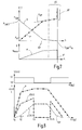
- FIG. 7 shows in schematic form diagrams of the actuating pressure P, a torque T developing therefrom in the friction clutch 12 as well as the cooling volume flow V over the path s of the piston or the rotational speed n of the electric motor 22.
- the upper diagram is based on the left side of a state in which the friction clutch 12 is closed, so that a high torque T can be transmitted from the friction clutch 12.
- the pressure P is initially 0.
- the volume flow V is at this output state usually 0.
- the electric motor 22 can be turned off usually, since a cooling of the clutch is usually not required here.
- the branch arrangement 45 switches over so that a fluid volume flow into the secondary branch 41 is abruptly interrupted so that, although fine regulation of the torque T is no longer possible because a targeted leakage over the secondary branch 41 is no longer present. In this operating range, however, such a fine control is not necessary. This is essentially necessary in the area of the grinding point KP. Consequently, the first threshold pressure P SW is in any case greater than the pressure P KP at which the friction point KP of the friction clutch is located.
- the path s SW may correspond to a stop travel s A , in which the piston 34 impinges on the stop 38.
- FIG. 7 is shown at .DELTA.P, that the pressure may need to be further increased, starting from the threshold value P SW in a variant, in order to switch the branch arrangement 45.
- ⁇ S the path range within which the branch arrangement 45 could switch is shown.
- the smallest value of ⁇ s is in any case greater than the waypoint KP at which the grinding point of the friction clutch is located.
- FIG. 7 is further indicated schematically at V 'that the switching arrangement 60 can reduce a cooling oil volume flow V either to 0 or left at a small value (for example by means of the aperture 42' in FIG. 5 ), whereby a volume flow V 'is adjusted.
- the switching arrangement 60 may be switched at a third threshold pressure P SW3 , which is smaller than the first threshold pressure P SW , but in any case greater than the grinding point pressure P KP .
- the friction clutch 12 is usually opened in the drive train 18 when 84 gear changes are to be performed in the multi-step transmission.
- the friction clutch 12 is then closed again, the pressure P drops to 0 again.
- P N a small value which is below a threshold at which the clutch could start to slip due to the correspondingly reduced torque T.
- the pressure P N is therefore preferably less than the pressure corresponding to a torque T currently required for transmitting drive power without the friction clutch 12 slipping.
- Fig. 8 shows timing diagrams, on the one hand, the switching positions S of the branch arrangement 45 and the actuating pressure P, the flow rate V (41) in the side branch 41 into, and the path S of the piston 34 of the fluid actuator 14.
- the clutch is closed.
- the branch arrangement 45 is in the position S1, in which a volume flow through the branch arrangement 45 can flow into the side branch 41.
- the speed n of the pump is increased so that the pressure P increases, as described above with reference to FIG Fig. 7 described.
- the pressure P increases at a lower rate, similar to the embodiment of FIG Fig.
- the volume flow V (41) increases at a lower rate, whereas the path s increases at a higher rate until a time t 3 at which a switching timing for the branching arrangement 45 is reached.
- the pressure P reaches the first threshold (see Fig. 7 ), whereupon the branch arrangement 45 switches, so that at the time t 3, the pressure P for holding the friction clutch 12 is kept high, the volume flow V (41) through the aperture 42 through but completely off, so that the clutch 12 with low energy consumption can be held in the open position.
- the pressure P is again reduced (by reducing the speed n of the pump assembly 24) so that at a time t 5/6 a second threshold is reached which is less than the first threshold and where the branch assembly 45 is again switches to the first position S1, so that again a volume flow is established by the secondary branch, in good time before reaching the engagement point KP, so that the closing of the clutch in the region of the engagement point KP can be sensitively controlled or adjusted.
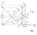
- Fig. 9 shows in schematic form the hysteresis described above concerning the first threshold P SW and the second threshold P SW2 .
- Fig. 9 a diagram of torque T and speed n above the pressure P.
- the speed n (22) is initially increased, whereby the flow rate V (41) increases and the torque T falls.
- the torque T is at a value of 0 or a residual drag torque.
- the engagement point P KP is reached to an operating point 2.
- the speed is further increased, and while, until an operating time 3, the pressure P the first Threshold P SW reached.
- the volume flow V (41) drops to zero, shown by an operating point 4/4 '.
- the speed n (22) of the pump assembly can be drastically reduced, since the pump no longer constantly has to promote a flow through the secondary branch at this time, but essentially only has to compensate for the potential leakage from the pump assembly on the way out can occur to the fluid actuator.
- the branch arrangement 45 again switches to the first position S1, whereby the volume flow V (41) from the operating point 5 'to the operating point 6' again increases, and at the same time the rotational speed n (22 ) of the pump assembly from the operating point 5 to the operating point 6 must be increased again in order to compensate for the now established volume flow can.
Landscapes
- Engineering & Computer Science (AREA)
- General Engineering & Computer Science (AREA)
- Physics & Mathematics (AREA)
- Fluid Mechanics (AREA)
- Mechanical Engineering (AREA)
- Hydraulic Clutches, Magnetic Clutches, Fluid Clutches, And Fluid Joints (AREA)
Abstract
Description
- Die vorliegende Erfindung betrifft eine Kupplungsanordnung, insbesondere für ein manuelles oder ein automatisiertes Kraftfahrzeug-Stufengetriebe, mit einer nasslaufenden Reibkupplung zur Anordnung zwischen einem Antriebsmotor und einem Stufengetriebe, mit einem Fluidaktuator zur Betätigung der Reibkupplung, mit einer Fluidversorgungseinrichtung, die einen Elektromotor und eine von dem Elektromotor angetriebene Pumpenanordnung aufweist, wobei die Pumpenanordnung über einen ersten Zweig mit dem Fluidaktuator verbunden ist, und mit einem Nebenzweig, über den ein Teil des von der Pumpenanordnung bereitgestellten Fluidvolumenstroms hin zu einem Niederdruckbereich leitbar ist.
- Ferner betrifft die vorliegende Erfindung einen Antriebsstrang mit einem Antriebsmotor und einer Kupplungsanordnung der oben bezeichneten Art. Schließlich betrifft die vorliegende Erfindung ein Verfahren zur Betätigung und ggf. zur Kühlung einer Kupplungsanordnung, insbesondere der oben beschriebenen Art.
- Auf dem Gebiet der Antriebsstränge für Kraftfahrzeuge dienen Reibkupplungen als Trenn- bzw. Anfahrkupplungen zwischen Antriebsmotor und einem Stufengetriebe. Der Antriebsmotor kann beispielsweise ein Verbrennungsmotor sein, kann jedoch auch eine Hybrid-Antriebseinheit sein. Das Stufengetriebe ist gewöhnlich ein Getriebe in Vorgelegebauweise mit einer Mehrzahl von Gangstufen, die über jeweilige Schaltkupplungen (Synchroneinheiten) ein- und auslegbar sind.
- Bei manuell betätigten Antriebssträngen dieser Art werden die Schaltkupplungen über einen Gangschalthebel im Fahrzeuginnenraum betätigt. Die Kupplung wird über ein Kupplungspedal betätigt. Die bislang zu diesem Zweck verwendeten Kupplungen sind trockene Reibkupplungen, die durch Federvorspannung normalerweise geschlossen sind, also durch Betätigung des Kupplungspedals in einen Schleifzustand gebracht und geöffnet werden können.
- Es ist auf dem Gebiet solcher Antriebsstränge ferner bekannt, die Getriebebetätigung und/oder die Kupplungsbetätigung zu automatisieren, wozu Aktuatoren wie beispielsweise Hydraulikaktuatoren verwendet werden.
- Beispielsweise ist es aus dem Dokument
WO 2006/128 637 A1 bekannt, eine Reibkupplung in Form einer Lamellenkupplung mittels eines Stufenkolbens zu betätigen, um einen Vorhub bis zum Erreichen eines Anliegens der Kupplung (Schleifpunkt) schnell durchfahren zu können. - Ferner offenbart das Dokument
DE 10 2012 002 162 A1 einen Fluidzylinder zur Betätigung einer Reibkupplung, wobei der Zylinder in eine Öffnungsrichtung der Reibkupplung vorgespannt ist (normally open) und wobei ein Druckanschluss einer elektromotorisch angetriebenen Pumpe direkt mit einem Betätigungsanschluss des einfach wirkenden Fluidzylinders verbunden ist. Die Pumpe kann dabei bidirektional antreibbar sein, wobei der Kolben mit einer Abdichteinrichtung verbunden sein kann, um den Fluidzylinder gegen einen Unterdruck abzudichten, wenn die Pumpe zum Abpumpen von Fluid aus dem Fluidraum verwendet wird. Zur Betätigung der Pumpenanordnung wird der Druck in dem Fluidzylinder durch Verändern der Drehzahl des Elektromotors eingestellt. Ein derartiger "Pumpenaktuator" kann mit wenigen Bauteilen realisiert werden. - Bei derartigen Pumpenaktuatoren ist es in der Regel auch nicht nötig, Druckspeicher im Hydraulikkreis vorzusehen, wie es beispielsweise aus dem Dokument
DE 10 2009 005 410 B4 bekannt ist. - Das Dokument
DE 10 2004 033 439 C5 offenbart eine weitere Form von Pumpenaktuator, wobei ein Motor zwei Pumpen antreibt, von denen eine für ein schnelles Schließen der Reibkupplung bei geringem Kraftaufwand ausgelegt ist und wobei die zweite Pumpe für eine Betätigung der Reibkupplung mit einer großen Kraft bei einem geringen Hub ausgelegt ist. - Sofern die in einem solchen Antriebsstrang verwendete Reibkupplung eine nasslaufende Kupplung ist, ist es auch bekannt, diese zu kühlen. Das Dokument
DE 10 2011 118 574 A1 offenbart beispielsweise eine Antriebsstrang-Kühlanordnung mit einem ersten Kühlkreis zur Kühlung einer Doppelkupplungsanordnung für ein Doppelkupplungsgetriebe und mit einem zweiten Kühlkreis zur Kühlung beispielsweise einer elektrischen Maschine und/oder eines Stufengetriebes. Die Kühlkreise sind dabei an unterschiedliche Pumpenanschlüsse einer einzelnen Pumpe angeschlossen, die mittels eines Elektromotors bidirektional antreibbar ist. Der Kühlmittel-Volumenstrom ist durch Verändern der Drehzahl des Pumpen-Elektromotors einstellbar. - Schließlich ist aus dem Dokument
DE 10 2011 102 277 A eine Kupplungsordnung für ein Kraftfahrzeug bekannt, die zwei Reibkupplungen aufweist, die mittels jeweiliger Aktuatoren betätigt werden. Zu deren Betätigung ist eine bidirektional mittels eines Elektromotors antreibbare Pumpe vorgesehen, die je nach Drehrichtung entweder die eine oder die andere Kupplung betätigt. Aus diesem Dokument ist es auch bekannt, bei Erreichen eines bestimmten Druckes von dem Volumenstrom zur Betätigung der Reibkupplung einen Kühl-Volumenstrom abzuzweigen, der über eine Blende begrenzt sein kann. Eine derartige Fluidversorgungseinrichtung für die Betätigungszylinder einerseits und die Kühleinrichtung andererseits kann jedoch die in einem Antriebsstrang vorkommenden Zustände nicht immer optimal abbilden. Sofern hingegen für die Betätigung einerseits und die Kühlung andererseits unterschiedliche Aktuatoren bzw. Fluidversorgungseinrichtungen verwendet werden, ergibt sich ein erhöhter Aufwand. Dies gilt insbesondere im Vergleich zu trockenen Reibkupplungen, bei denen eine Fluidkühlung nicht vorgesehen ist. - Trockenkupplungen haben generell Nachteile bezüglich Gewicht, Massenträgheitsmoment, Ansteuerbarkeit, Wärmeabfuhr etc.. Nasslaufende Reibkupplungen haben Nachteile wegen des größeren Bauteilaufwandes für die Automatisierung.
- Sofern zur Betätigung einer Reibkupplung ein Fluidaktuator verwendet wird, dessen Stellgröße (Druck oder Weg) durch einen Pumpenaktuator geregelt wird, also durch Regeln der Drehzahl eines Motors zum Antrieb der Pumpenanordnung, ist generell für eine feinfühlige Regelung eine gewisse Leckage vorteilhaft. In vielen Fällen ist daher ein Druckanschluss einer Pumpenanordnung und/oder ein Fluidaktuator über eine Blende mit einem Tank verbunden. Gerade bei hohen Drücken führt dies jedoch zu einer vergleichsweise hohen Verlustleistung, was die CO2-Emissionen eines Fahrzeugs erhöhen kann, das mit einer derartigen Kupplungsanordnung ausgestattet ist.
- Es ist vor diesem Hintergrund eine Aufgabe der Erfindung, eine verbesserte Kupplungsanordnung, einen verbesserten Antriebsstrang sowie ein verbessertes Verfahren zum Betätigen einer Kupplungsanordnung anzugeben, wobei der Bauteilaufwand möglichst gering sein soll, so dass sich Kosten-, Package- und/oder Gewichtsvorteile ergeben können, und/oder wobei unterschiedliche Zustände effektiver abgebildet werden können, insbesondere hinsichtlich des Wirkungsgrades.
- Die obige Aufgabe wird bei der eingangs genannten Kupplungsanordnung durch eine Abzweiganordnung gelöst, die dazu ansteuerbar ist, um den zu dem Nebenzweig geleiteten Neben-Fluidvolumenstrom zu reduzieren, wenn ein Betätigungsdruck in dem Fluidaktuator einen Schwellendruck überschreitet und/oder der Fluidaktuator einen Schwellenweg überschreitet.
- Ferner wird die obige Aufgabe gelöst durch einen Antriebsstrang mit einem Antriebsmotor, mit einer Kupplungsanordnung, die eine Reibkupplungsanordnung mit einem Eingangsglied aufweist, das mit dem Antriebsmotor verbunden ist, und mit einem Stufengetriebe, dessen Eingang mit einem Ausgangsglied der Reibkupplungsanordnung verbunden ist, wobei die Kupplungsanordnung eine erfindungsgemäße Kupplungsanordnung ist.
- Schließlich wird die obige Aufgabe gelöst durch ein Verfahren zur Betätigung und ggf. zur Kühlung einer Kupplungsanordnung, insbesondere einer Kupplungsanordnung der erfindungsgemäßen Art, wobei die Kupplungsanordnung eine nasslaufende Reibkupplung sowie eine Fluidversorgungseinrichtung aufweist, die mit einem Fluidaktuator zur Betätigung der Reibkupplung verbunden ist, wobei die Fluidversorgungseinrichtung dazu ausgebildet ist, einen geregelten Betätigungsdruck für den Fluidaktuator einzustellen und mit einem Nebenzweig verbunden zu werden, über den bedarfsweise ein Teil des von der Pumpenanordnung bereitgestellten Fluidvolumenstroms hin zu einem Niederdruckbereich leitbar ist, wobei das Verfahren den Schritt beinhaltet, den zu dem Nebenzweig geleiteten Fluidvolumenstrom zu reduzieren, wenn ein Betätigungsdruck in den Fluidaktuator einen Schwellendruck überschreitet und/oder der Fluidaktuator einen Schwellenweg überschreitet.
- Durch die Abzweiganordnung ist es möglich, bei hohen Betätigungsdrücken den Neben-Fluidvolumenstrom zu reduzieren, was in vielen Fällen zu einer Energieeinsparung führen kann.
- Die Pumpenanordnung ist vorzugsweise direkt über den ersten Zweig mit dem Fluidaktuator verbunden. Unter einer direkten Verbindung wird vorliegend verstanden, dass zwischen der Pumpenanordnung und dem Fluidaktuator kein Druckregelventil oder Druckreduzierventil angeordnet ist. Derartige Ventile sind als Proportionaloder Schieberventile ausgebildet, die erhöhte Anforderungen hinsichtlich Reinheit bei der Montage stellen. Ferner sind diese Ventile teuer. Eine direkte Verbindung kann folglich eine ununterbrochene Verbindung zwischen der Pumpenanordnung und dem Fluidaktuator sein, kann jedoch auch eine durch ein Ventil hergestellte direkte Verbindung sein, beispielsweise eine Verbindung durch ein Wegeventil hindurch.
- Die Abzweiganordnung ist vorzugsweise so ausgebildet, dass in jedem ihrer Betriebszustände eine solche direkte Verbindung zwischen der Pumpenanordnung und dem Fluidaktuator eingerichtet ist, und zwar vorzugsweise durch die Abzweiganordnung hindurch.
- Die Abzweiganordnung wird hierbei vorzugsweise durch ein Wegeventil gebildet. Ein Wegeventil ist zum einen kostengünstiger als Schieberventile und erfordert keine hohen Anforderungen hinsichtlich der Reinheit bei der Montage etc.
- Durch den Nebenzweig wird vorzugsweise eine definierte Leckage eingerichtet. Bei einer direkten Verbindung zwischen Pumpenanordnung und Fluidaktuator wird eine Stellgröße des Fluidaktuators wie beispielsweise der Betätigungsdruck oder der Betätigungsweg durch Regeln der Drehzahl der Pumpenanordnung (also Regeln der Drehzahl des Elektromotors) eingeregelt. Auch aus diesem Grund sind in dem ersten Zweig keine Druckregelventile oder ähnliches erforderlich.
- Durch das Einrichten einer definierten Leckage in dem Nebenzweig kann hierbei die Regelbarkeit dieser Stellgröße deutlich verbessert werden, vorzugsweise sowohl hinsichtlich Ansprechverhalten als auch Regelgenauigkeit. Dies spielt insbesondere in solchen Stellbereichen eine Rolle, bei denen einen Momentenübertragung über die nasslaufenden Reibkupplung genau eingestellt wird, also beispielsweise im Bereich eines Schleifpunktes wie eines Eingriffspunktes bzw. Kiss-Punktes. Wenn die Reibkupplung hingegen in einem ihrer Endbereiche ist, beispielsweise vollständig geöffnet oder vollständig geschlossen, spielt die Regelbarkeit normalerweise keine so große Rolle mehr. Daher kann beispielsweise bei höheren Betätigungsdrücken der Neben-Fluidvolumenstrom reduziert werden, über den die definierte Leckage eingerichtet ist, um auf diese Weise Energie zu sparen.
- In manchen Fällen ist der Nebenzweig ferner mit einer Kühleinrichtung zur Fluidkühlung der Reibkupplung verbunden, so dass der Neben-Fluidvolumenstrom einen Kühlvolumenstrom beinhaltet.
- Durch die Abzweiganordnung kann zudem für diesen Fall das Problem gelöst werden, dass ein Betätigungsdruck und ein Kühlvolumenstrom im Stand der Technik zwangsweise miteinander korrelieren. Dann, wenn der Betätigungsdruck groß ist, ist die Reibkupplung beispielsweise vollständig geschlossen oder vollständig geöffnet (je nachdem, ob die Reibkupplung normally open oder normally closed ist). In diesen Fällen wird jedoch in der Regel keine hohe Kühlleistung benötigt, da die Kühlleistung hauptsächlich dann benötigt wird, wenn die Reibkupplung sich in einem Schleifzustand befindet. Durch das Bereitstellen eines hohen Kühlvolumenstromes bei einem hohen Betätigungsdruck können jedoch Schleppverluste erzeugt werden, die den Wirkungsgrad und/oder den Komfort des Antriebsstranges verringern.
- Beispielsweise können die Schleppverluste dazu führen, dass sich Schaltkupplungen schwieriger einlegen lassen. Dies ist insbesondere dann problematisch, wenn zwar die Kupplung automatisiert mittels des Fluidaktuators betätigt wird, die Gangstufen in dem Stufengetriebe jedoch manuell betätigt werden.
- Durch die Abzweiganordnung der Kupplungsanordnung ist es nun vorzugsweise möglich, den Fluidvolumenstrom zu der Kühleinrichtung zu reduzieren, wenn der Betätigungsdruck einen Schwellendruck überschreitet und/oder der Fluidaktuator einen Schwellenweg überschreitet.
- Folglich können für diesen Fall Schleppverluste insbesondere bei hohen Betätigungsdrücken bzw. vollem Betätigungsweg des Fluidaktuators verringert werden.
- Die Aufgabe wird somit vollkommen gelöst.
- Gemäß einer besonders bevorzugten Ausführungsform ist die Reibkupplung in eine geschlossene Position vorgespannt.
- Eine derartige Reibkupplung vom "Normally-closed"-Typ ist in solchen Fällen vorteilhaft, wenn der Antriebsstrang eine einzelne Reibkupplung aufweist und/oder die Schaltkupplungen zur Gangbetätigung des Getriebes manuell betätigt werden.
- Durch die normalerweise geschlossene Position kann hierbei ein hoher Wirkungsgrad erreicht werden, da der Fluidaktuator nur dann einzusetzen ist, wenn die Kupplung geöffnet wird, beispielsweise bei Gangwechsel und/oder im Stand vor einem Anfahrvorgang oder dergleichen.
- Gemäß einer weiteren Ausführungsform ist der Schwellendruck größer als ein Schleifpunkt-Betätigungsdruck, bei dem die Reibkupplung ihren Eingriffspunkt ("Kisspoint") hat. Hierdurch kann gewährleistet werden, dass für den Fall, dass der Nebenzweig eine definierte Leckage beinhaltet, diese definierte Leckage jedenfalls dann zur Verfügung steht, wenn sich die Reibkupplung in dem Schleifzustand befindet. Hierdurch kann während des Schleifzustandes der Reibkupplung eine gute Regelbarkeit erreicht werden, also dann, wenn die Stellgröße der Reibkupplung durch Regeln der Drehzahl der Pumpenanordnung eingestellt bzw. geregelt wird. In Fällen, bei denen der Nebenzweig mit einer Kühleinrichtung verbunden ist, kann zudem ggf. gewährleistet werden, dass der Fluidvolumenstrom zur Kühlung der Reibkupplung nicht reduziert ist, wenn sich die Reibkupplung in dem Schleifzustand befindet. Vielmehr wird der Volumenstrom, der der Kühleinrichtung bereitgestellt wird, erst dann reduziert, wenn die Kupplung beispielsweise vollständig geöffnet ist (bei einer Normally-closed-Kupplung). In diesem Fall können die Schleppverluste effizient vermieden werden, da der Kupplungsvolumenstrom reduziert ist, wenn die Kupplung geöffnet ist und während dieser Phase Gangwechsel durchgeführt werden, da Synchronisierungsvorgänge aufgrund der verringerten Schleppverluste hierdurch erleichtert werden können.
- Gemäß einer bevorzugten Ausführungsform ist die Abzweiganordnung dazu ansteuerbar, um den zu dem Nebenzweig geleiteten Neben-Fluidvolumenstrom zu unterbrechen, wenn der Betätigungsdruck in dem Fluidaktuator den Schwellendruck überschreitet und/oder der Fluidaktuator den Schwellenweg überschreitet.
- Für diesen Fall kann der Neben-Fluidvolumenstrom komplett unterbrochen werden, so dass beispielsweise bei vollständig geöffneter Kupplung und folglich hohem Betätigungsdruck (bei einer Normally-closed-Kupplung) kein Leckagevolumenstrom mehr abfließt und folglich eine hohe Energieeinsparung erreichbar ist.
- Gemäß einer weiteren bevorzugten Ausführungsform ist die Abzweiganordnung dazu ausgebildet, den Fluidvolumenstrom von der Pumpenanordnung in einen Fluidvolumenstrom zu dem Fluidaktuator und einen Neben-Fluidvolumenstrom zu dem Nebenzweig aufzuteilen, wenn der Betätigungsdruck in dem Fluidaktuator einen zweiten Schwellendruck unterschreitet und/oder der Fluidaktuator einen zweiten Schwellenweg unterschreitet.
- Der erste und der zweite Schwellendruck bzw. der erste und der zweite Schwellenweg können identisch sein, sind jedoch vorzugsweise unterschiedlich, wobei der zweite Schwellendruck vorzugsweise kleiner ist als der erste Schwellendruck und wobei der zweite Schwellenweg vorzugsweise kleiner ist als der erste Schwellenweg. Wenn der erste und der zweite Schwellenwert sich jeweils unterscheiden, kann für die Betätigung der Abzweiganordnung eine gewisse Hysterese eingerichtet werden, so dass unnötige Schaltvorgänge der Abzweiganordnung vermieden werden.
- In einer bevorzugten Ausführungsform kann die Abzweiganordnung als 3/2-Wegeventil ausgebildet sein, wobei in einer Betätigungsposition der Pumpen-Fluidvolumenstrom aufgeteilt wird, und wobei in der anderen Position der Pumpen-Fluidvolumenstrom ausschließlich zu dem Fluidaktuator geführt wird.
- Gemäß einer bevorzugten Ausführungsform weist der Nebenzweig eine Blende auf.
- Für diesen Fall kann der Nebenzweig beispielsweise direkt mit einem Niederdruckbereich wie einem Tank verbunden sein. Die Blende stellt für diesen Fall beispielsweise eine definierte Leckage bereit, über die die Regelbarkeit der Stellgröße der Reibkupplung verbessert werden kann. Die Blende ist vorzugsweise eine passive starre Blende.
- Gemäß einer weiteren bevorzugten Ausführungsform ist der Nebenzweig mit einer Kühleinrichtung zur Fluidkühlung der Reibkupplung verbunden.
- Über die Kühleinrichtung fließt ein Kühlvolumenstrom hin zu der Reibkupplung, um diese zu kühlen. Die Kühlung ist, wie oben erwähnt, insbesondere dann notwendig, wenn sich die Reibkupplung im Bereich ihres Schleifpunktes befindet. Bei vollständig geöffneter oder vollständig geschlossener Kupplung kann dieser Volumenstrom folglich reduziert werden. Während sich die Reibkupplung im Schleifzustand oder im Bereich des Schleifzustandes befindet, wird hingegen über den Kühlvolumenstrom nicht nur eine Kühlung bereitgestellt, es wird auch vorzugsweise eine definierte Leckage bereitgestellt, über die die Regelbarkeit der Stellgröße der Reibkupplung verbessert werden kann.
- Hierbei ist es von besonderem Vorzug, wenn der Nebenzweig eine Umschaltanordnung aufweist, die dazu ansteuerbar ist, um einen Fluidvolumenstrom zu der Kühleinrichtung zu reduzieren, wenn ein Betätigungsdruck in dem Fluidaktuator einen dritten Schwellendruck überschreitet und/oder der Fluidaktuator einen dritten Schwellenweg überschreitet.
- Der dritte Schwellendruck bzw. der dritte Schwellenweg sind insbesondere kleiner als der erste Schwellendruck bzw. der erste Schwellenweg. Hierdurch ist es vorzugsweise möglich, in dem Nebenzweig zunächst den Kühlvolumenstrom zu reduzieren und anschließend (bei Erreichen des ersten Schwellenwertes) den Neben-Fluidvolumenstrom insgesamt zu reduzieren bzw. vorzugsweise abzuschalten.
- Insgesamt ist es ferner vorteilhaft, wenn der Nebenzweig mit einem Treibanschluss einer Saugstrahlpumpe verbunden ist. Diese Ausführungsform stellt in Verbindung mit dem Oberbegriff des Anspruchs 1 eine eigene Erfindung dar.
- Ein Sauganschluss einer solchen Saugstrahlpumpe kann beispielsweise mit einem Tank verbunden sein, wobei ein Diffusor einer solchen Saugstrahlpumpe vorzugsweise mit der Reibkupplung zum Zwecke von deren Kühlung und/oder Schmierung verbunden ist.
- Über den Treibanschluss der Saugstrahlpumpe kann eine definierte Leckage bereitgestellt werden, ähnlich der Funktion einer Blende, so dass es für diesen Fall vorzugsweise nicht erforderlich ist, den Nebenzweig über eine Blende mit dem Tank zu verbinden.
- Gemäß einer bevorzugten Ausführungsform ist die Pumpenanordnung durch eine einzelne Pumpe gebildet, die einen ersten Pumpenanschluss aufweist, der mit der Abzweiganordnung verbunden ist. Eine direkte Verbindung der Pumpenanordnung mit dem Fluidaktuator über die Abzweiganordnung kann vorzugsweise bedeuten, dass in dem ersten Zweig keine Proportional- oder Servoventile zur Druckregelung bereitgestellt werden müssen. Denn diese führen bei der Montage derartiger Kupplungsanordnungen zu erhöhten Reinheitsanforderungen. Vorliegend kann der Betätigungsdruck für die Reibkupplung über das Einstellen der Drehzahl des Elektromotors geregelt werden.
- Bei dieser Ausführungsform kann die einzelne Pumpe nach der Art eines Pumpenaktuators angetrieben werden, indem der Betätigungsdruck durch Einstellen der Drehzahl des Elektromotors geregelt wird.
- In dem Nebenzweig kann der von der Pumpenanordnung bereitgestellte Volumenstrom in einer Ausführungsform direkt zu einem Kühlanschluss der Reibkupplung geführt werden. In einer Variante kann in dem Nebenzweig auch eine Strahlpumpe derart angeordnet werden, dass zumindest ein Teil des Neben-Fluidvolumenstroms mit einem Treibanschluss einer solchen Saugstrahlpumpe verbunden wird. Der Sauganschluss einer solchen Saugstrahlpumpe kann in diesem Fall mit einem Tank bzw. einem Reservoir verbunden werden. Hierdurch kann der Volumenstrom, der zur Kühlung bereitgestellt wird, gegenüber dem von der Pumpenanordnung bereitgestellten Volumenstrom signifikant erhöht werden.
- Derartige Saugstrahlpumpen sind vergleichsweise kostengünstig realisierbar und weisen in der Regel keine beweglichen Bauteile auf, so dass sie ebenfalls bei relativ geringen Reinheitsanforderungen hergestellt werden können.
- Ferner ist es in einer weiteren alternativen Ausführungsform bevorzugt, wenn die Pumpenanordnung eine Betätigungspumpe und eine Kühlpumpe aufweist, wobei ein Pumpenanschluss der Betätigungspumpe mit der Abzweiganordnung verbunden ist und wobei ein Pumpenanschluss der Kühlpumpe mit einer Kühleinrichtung der Reibkupplung verbunden ist.
- Bei dieser Ausführungsform können für das Betätigen der Reibkupplung und für das Kühlen der Reibkupplung unterschiedliche Pumpen verwendet werden, beispielsweise eine Volumenpumpe für die Kühlpumpe und eine Druckpumpe für die Betätigungspumpe.
- Es versteht sich bei dieser Ausführungsform jedoch, dass die Betätigungspumpe und die Kühlpumpe vorzugsweise gemeinsam von dem Elektromotor angetrieben werden. Allerdings ist es in manchen Ausführungsformen auch denkbar, den Elektromotor über unterschiedliche Übersetzungen mit den beiden Pumpen zu verbinden, um gegebenenfalls unterschiedliche Pumpencharakteristika zu realisieren.
- Generell ist es hierbei denkbar, dass die Betätigungspumpe und die Kühlpumpe jeweils unidirektional arbeiten, wobei deren jeweilige zweite Pumpenanschlüsse jeweils als reine Sauganschlüsse ausgebildet sind.
- In einer alternativen bevorzugten Ausführungsform sind die Betätigungspumpe und die Kühlpumpe bidirektional antreibbar, wobei ein erster und ein zweiter Pumpenanschluss der Kühlpumpe mit dem Nebenzweig über eine Rückschlagventilanordnung verbunden sind, die so ausgebildet ist, dass in beiden Drehrichtungen der Kühlpumpe Fluid in den zweiten Zweig geleitet wird.
- Ein bidirektionales Antreiben der Betätigungspumpe hat den Vorteil, dass Fluid aus dem Fluidaktuator gegebenenfalls schneller wieder abgesaugt werden kann, das Fluid also nicht allein durch eine Vorspannfeder herausgedrückt werden muss. Dies kann das Ansprechverhalten und die Regelbarkeit verbessern.
- Für die Kühlpumpe ist hingegen vorgesehen, dass die Rückschlagventilanordnung dafür sorgt, dass die Kühlpumpe unabhängig von der Drehrichtung einen Volumenstrom zum Kühlen der Kühleinrichtung bereitstellen kann.
- Generell ist es denkbar, die Abzweiganordnung auf verschiedene Art und Weise zu realisieren, beispielsweise durch Einflussnahme auf die Kopplung zwischen Elektromotor und Pumpenanordnung.
- Von besonderem Vorzug ist es jedoch, wenn die Abzweiganordnung eine Ventilanordnung aufweist, die zur Ventilbetätigung in Abhängigkeit von einem Betätigungsdruck mit dem Fluidaktuator hydraulisch verbunden ist.
- Mit einer derartigen Ventilanordnung, die über den Betätigungsdruck druckgesteuert ist, beispielsweise gegen eine Vorspannfeder, kann der erste Schwellendruck auf konstruktiv einfache Weise eingestellt werden.
- Generell ist es bevorzugt, wenn die Ventilanordnung ein eigenes Ventil ist, das in örtlicher Nähe zu der Pumpenanordnung angeordnet wird, also außerhalb der Reibkupplung.
- In einer vorteilhaften Ausgestaltung betrifft die vorliegende Erfindung folglich die Ansteuerung einer nassen Kupplung für ein Kraftfahrzeug. Die Ansteuerung des Fluidaktuators kann mittels eines einzigen Aktuators (mittels eines Elektromotors) erfolgen. Die nasse Reibkupplung kann durch einen Fluiddruck gesteuert sein, den eine Pumpenanordnung (zum Beispiel eine Gerotorpumpe etc.) in Kombination mit dem Elektromotor zur Verfügung stellt. Ferner kann die Kupplung ggf. mit Kühlöl versorgt werden, das von derselben Pumpenanordnung über hydraulische Elemente aus dem Hydraulikkreis abgezweigt wird. In manchen Varianten kann ein Rückwärtsdrehen der Pumpe zur Hauptversorgung des Kühlölzweigs verwendet werden. Zur Erhöhung des Kühlölvolumenstroms kann eine Saugstrahlpumpe verwendet werden. Anstelle einer einzelnen Pumpe kann an den Elektromotor eine zweite Pumpe angeschlossen werden, die ausschließlich den Kühlvolumenstrom liefert.
- Gegenüber Trockenkupplungen wird durch die nasse Reibkupplung eine Reihe von Vorteilen erzielt, insbesondere hinsichtlich Gewicht, Massenträgheitsmoment, Ansteuerbarkeit, Wärmeabfuhr etc.
- Insgesamt ergibt sich eine kosten-, package- und gewichtsgünstige Aktuierung für den Öldruck zur Kupplungsbetätigung und ggf. den Kühlölvolumenstrom zur Kupplungskühlung, mit einer geringen Anzahl an Bauteilen.
- Obgleich die vorliegende Erfindung bevorzugt in Verbindung mit einer "Normally-closed"-Reibkupplung verwendet wird, lassen sich die verschiedenen Lösungen auch auf eine "Normally-open"-Kupplung anwenden. Bei Kombination mit einer Normallyopen-Reibkupplung ist es vorteilhaft, wenn man bei offener Kupplung nachkühlen kann, jedoch auch zum Synchronisieren den Kühlölvolumenstrom ganz abschalten kann. Da das volle Moment in diesem Fall bei hohen Betätigungsdrücken erreicht wird, kann bei hohen Drücken eine weitere Umschaltstellung vorgesehen werden, die den Kühlölvolumenstrom reduziert, wenn die Kupplung geschlossen ist.
- Mit anderen Worten könnte man bei einer solchen Variante auch vorsehen, dass eine Reduzierung des Kühlölvolumenstromes auch erfolgt, wenn der Betätigungsdruck in dem ersten Zweig einen weiteren Schwellendruck (kleinen Druck) unterschreitet und/oder der Fluidaktuator einen weiteren (kleineren) Schwellenweg unterschreitet.
- Sofern die Reibkupplung eine Normally-open-Kupplung ist, wie oben erwähnt, kann bei Betriebstemperatur eine Leckage durch die Pumpenanordnung selbst eventuell ausreichend sein, um eine gute Steuerung bzw. Regelbarkeit zu gewährleisten, insbesondere dann, wenn das volle Drehmoment abverlangt wird und Maximaldruck anliegen muss. Auch in diesen Fällen kann der Nebenzweig ggf. abgeschaltet werden, so dass eine energieoptimierte Aktuierung möglich ist.
- Insgesamt ergeben sich mit der Erfindung ein hohes Energiesparpotential und mittelbar eine CO2-Reduzierung.
- Es versteht sich, dass die vorstehend genannten und die nachstehend noch zu erläuternden Merkmale nicht nur in der jeweils angegebenen Kombination, sondern auch in anderen Kombinationen oder in Alleinstellung verwendbar sind, ohne den Rahmen der vorliegenden Erfindung zu verlassen.
- Ausführungsbeispiele der Erfindung sind in der Zeichnung dargestellt und werden in der nachfolgenden Beschreibung näher erläutert. Es zeigen:
- Fig. 1
- eine schematische Darstellung einer ersten Ausführungsform einer erfindungsgemäßen Kupplungsanordnung;
- Fig. 2
- eine schematische Darstellung einer weiteren Ausführungsform einer erfindungsgemäßen Kupplungsanordnung;
- Fig. 3
- eine schematische Darstellung eines Antriebsstranges eines Kraftfahrzeuges mit einer Reibkupplung, die Bestandteil einer erfindungsgemäßen Kupplungsanordnung darstellen kann;
- Fig. 4
- eine schematische Darstellung einer weiteren Ausführungsform einer erfindungsgemäßen Kupplungsanordnung;
- Fig. 5
- eine alternative Ausführungsform einer Ventilanordnung für die Kupplungsanordnung der
Figur 4 ; - Fig. 6
- eine alternative Ausführungsform einer Ventilanordnung für die Kupplungsanordnung der
Figur 4 ; - Fig. 7
- ein Diagramm von Betätigungsdruck und Kupplungsmoment über dem Kupplungsweg sowie ein Diagramm von Kühlölvolumenstrom über der Drehzahl der Pumpenanordnung;
- Fig. 8
- ein Zeitablaufdiagramm von Schaltzuständen einer Abzweiganordnung sowie ein Diagramm von Betätigungsdruck, Volumenstrom und Kupplungsweg über der Zeit; und
- Fig. 9
- eine Darstellung von Kupplungsmoment und Drehzahl einer Pumpenanordnung über dem Betätigungsdruck.
- In
Figur 1 ist in schematischer Form eine Kupplungsanordnung für einen Kraftfahrzeug-Antriebsstrang schematisch dargestellt und generell mit 10 bezeichnet. - Die Kupplungsanordnung 10 beinhaltet eine nasslaufende Reibkupplung 12 in Form einer Lamellenkupplung, einen Fluidaktuator 14 in Form eines einfach wirkenden Hydraulikzylinders zur Betätigung der Reibkupplung 12 sowie eine Kühleinrichtung 16 zur Kühlung der Reibkupplung 12 durch Zuführen von Kühlöl.
- Die Kupplungsanordnung 10 beinhaltet ferner eine Fluidversorgungseinrichtung 20. Die Fluidversorgungseinrichtung 20 weist einen Elektromotor 22 auf, der eine Pumpenanordnung 24 antreibt, und zwar mit einer Drehzahl n. Die Pumpenanordnung 24 beinhaltet in der Ausführungsform der
Figur 1 eine einzelne unidirektionale Pumpe, die einen Sauganschluss 26 aufweist, der mit einem Tank bzw. Reservoir 25 verbunden ist. Die Pumpe weist ferner einen Druckanschluss 28 auf, über den Fluid für den Fluidaktuator 14 und die Kühleinrichtung 16 bereitgestellt wird. Der Sauganschluss 26 und der Druckanschluss 28 können jeweils mit Fluidfiltern verbunden sein, die inFigur 1 dargestellt, jedoch nicht näher bezeichnet sind. - Die Fluidversorgungseinrichtung 20 weist ferner einen ersten Zweig 30 auf, der den Druckanschluss 28 direkt mit einem Betätigungsanschluss 31 des Fluidaktuators 14 verbindet. Unter einer direkten Verbindung wird vorliegend verstanden, dass in dem ersten Zweig 30 keine Proportional- oder Servoventile enthalten sind, die gewöhnlich zur Druckregelung verwendet werden. Der in dem ersten Zweig 30 bereitgestellte Druck P wird vielmehr durch Regeln der Drehzahl n des Elektromotors 22 eingestellt.
- Der Betätigungsanschluss 31 des Fluidaktuators 14 ist mit einem Zylinderraum 32 verbunden, in dem ein Kolben 34 verschieblich gelagert ist. Der Kolben 34 ist mit der Reibkupplung 12 zu deren Betätigung gekoppelt. Dem Fluidaktuator 14 ist ferner eine Feder 36 zugeordnet, die den Kolben 34 in eine Position vorspannt, bei der die Reibkupplung 12 geschlossen ist ("normally closed"). Durch Befüllen des Zylinderraums 32 wird der Kolben 34 gegen die Feder 36 in eine Position überführt, bei der die Reibkupplung 12 geöffnet ist. Eine maximale Öffnungsposition des Kolbens 34 ist durch einen Anschlag 38 einstellbar, der in dem Fluidaktuator 14 angeordnet ist.
- An den ersten Zweig 30 kann eine Druckmesseinrichtung 40 angeschlossen sein, die den Druck P in dem ersten Zweig 30 und folglich in dem Zylinderraum 32 misst.
- Die Fluidversorgungseinrichtung 20 weist ferner einen Nebenzweig 41 auf. Der Nebenzweig 41 dient vorzugsweise zur Einrichtung einer gezielten Leckage, und zwar insbesondere für den Fall, dass der in dem ersten Zweig 30 bereitgestellte Druck P durch Regeln der Drehzahl n des Elektromotors 22 eingestellt wird. Hierdurch kann die Regelbarkeit verbessert werden. In einer Ausführungsform kann der Nebenzweig 41 hierzu eine Blende 42 aufweisen.
- Die Fluidversorgungseinrichtung 20 beinhaltet ferner einen Niederdruckbereich 44, innerhalb dessen die Blende 42 angeordnet sein kann. Der Nebenzweig 41 ist generell dazu ausgebildet, einen Neben-Fluidvolumenstrom zu dem Niederdruckbereich 44 zuzuführen.
Fig. 1 zeigt ferner, dass der Niederdruckbereich 44 die Kühleinrichtung 16 beinhalten kann, also beispielsweise eine Fluidleitung des Niederdruckbereiches 44 mit einem Kühlanschluss 46 der Reibkupplung 12 verbunden sein kann. Folglich kann zumindest ein Teil des Neben-Fluidvolumenstroms in Form eines Kühlfluid-Volumenstroms der Reibkupplung 12 zugeführt werden. Die gezielte Leckage kann in dem Niederdruckbereich 44 folglich auch über den Kühlanschluss 46 bereitgestellt werden, und zwar alternativ zu der Blende 42 oder zusätzlich hierzu. - Der Druckanschluss 28 der Pumpenanordnung 24 ist über eine Abzweiganordnung 45 sowohl mit dem ersten Zweig 30 (und folglich mit dem Fluidaktuator 14) und mit dem Nebenzweig 41 verbunden. Die Abzweiganordnung 45 ist vorliegend als Ventilanordnung 45a ausgebildet, und zwar in Form eines 3/2-Wegeventils 45b. Die Ventilanordnung 45a ist mittels einer Feder 45c in eine erste Stellung S1 vorgespannt und kann mittels einer Druckbetätigungseinrichtung 45d in die zweite Stellung S2 versetzt werden, und zwar gegen die Kraft der Feder 45c. Die Druckbetätigungseinrichtung 45d ist hierbei mit dem ersten Zweig 30 verbunden, also mit dem Fluidaktuator 14.
- Folglich wird die Ventilanordnung 45a der Abzweiganordnung 45 in Abhängigkeit von dem Betätigungsdruck P in dem Fluidaktuator 14 von der ersten Stellung S1 in die zweite Stellung S2 bewegt.
- In der ersten Stellung S1 ist der Pumpenanschluss 28 sowohl mit dem ersten Zweig 30 als auch mit dem Nebenzweig 41 verbunden. In der zweiten Stellung S2 ist der Pumpenanschluss 28 lediglich mit dem ersten Zweig 30 verbunden, und der Anschluss zu dem Nebenzweig 41 ist unterbrochen.
- Die Feder 45c ist so ausgebildet, dass die Ventilanordnung 45a von der ersten Stellung S1 in die zweite Stellung S2 geschaltet wird, wenn der Betätigungsdruck P in dem Fluidaktuator 14 einen Schwellendruck PSW überschreitet. Alternativ hierzu ist es möglich, die Abzweiganordnung 45 weggesteuert zu betätigen, und zwar in Abhängigkeit von einem Betätigungsweg des Kolbens 34 des Fluidaktuators 14, derart, dass die Abzweiganordnung 45 in die zweite Stellung S2 schaltet, wenn der Kolben 34 des Fluidaktuators einen Schwellenweg SSW überschreitet.
- In manchen Varianten kann die Abzweiganordnung 45 dazu ausgebildet sein, den Fluidvolumenstrom von der Pumpenanordnung in einen Fluidvolumenstrom zu dem Fluidaktuator und einen Neben-Fluidvolumenstrom zu dem Nebenzweig 41 aufzuteilen, wenn der Betätigungsdruck P in dem Fluidaktuator 14 einen zweiten Schwellendruck unterschreitet und/oder der Fluidaktuator 14 einen zweiten Schwellenweg unterschreitet.
- Nachfolgend werden weitere Ausführungsformen von Kupplungsanordnungen beschrieben, die hinsichtlich Aufbau und Funktionsweise generell der Kupplungsanordnung 10 der
Fig. 1 entsprechen. Gleiche Elemente sind daher durch gleiche Bezugszeichen gekennzeichnet. Im Folgenden werden im Wesentlichen die Unterschiede erläutert. - In
Fig. 2 ist eine Kupplungsanordnung 10' gezeigt, deren Pumpenanordnung 24 und Abzweiganordnung 45 identisch sind wie bei der Ausführungsform derFig. 1 . Lediglich in dem Niederdruckbereich 44 sind einige Änderungen vorgesehen. - Zum einen ist zu erkennen, dass der Kühlanschluss 46 der Reibkupplung 12 mit einer Saugstrahlpumpe 48 verbunden ist. Die Saugstrahlpumpe 48 weist einen Treibanschluss 50, einen Sauganschluss 52 und einen Diffusor 54 auf. Der Treibanschluss 50 der Saugstrahlpumpe 48 ist über ein Rückschlagventil 56 mit der Abzweiganordnung 45 verbindbar, genauer mit dem Nebenzweig 41. Der Sauganschluss 52 der Saugstrahlpumpe 48 ist über ein nicht näher bezeichnetes Rückschlagventil mit dem Tank 45 verbunden. Der Diffusor 54 ist mit dem Kühlanschluss 46 verbunden und liefert den Volumenstrom zum Kühlen/Schmieren der Reibkupplung 12, der sich aus einem an dem Treibanschluss 50 bereitgestellten Volumenstrom und dem über den Sauganschluss 52 angesaugten Volumenstrom zusammensetzt. Das Bereitstellen einer solchen Saugstrahlpumpe 48 in dem Niederdruckbereich 44 ist optional, kann also auch bei der Ausführungsform der
Fig. 1 vorgesehen sein. Alternativ kann bei der vorliegenden Ausführungsform einer Kupplungsanordnung 10' die Saugstrahlpumpe 48 auch weggelassen werden. - Der Niederdruckbereich 44 der Kupplungsanordnung 10' beinhaltet ferner eine Umschaltanordnung 60, die dazu ansteuerbar bzw. ausgebildet ist, um einen Fluidvolumenstrom V von der Pumpenanordnung 24 zu der Kühleinrichtung 16 zu reduzieren, wenn der Betätigungsdruck P in dem ersten Zweig 30 einen Schwellendruck (dritter Schwellendruck) überschreitet.
- Der dritte Schwellenwert ist vorzugsweise kleiner gleich dem ersten Schwellenwert.
- Die Umschaltanordnung 60 beinhaltet eine Ventilanordnung 62, die vorliegend ein 3/2-Wegeventil 64 aufweist. Das Ventil 64 ist mittels einer Feder 66 in eine erste Position vorgespannt, bei der ein ungehinderter Durchfluss von dem Nebenzweig 41 hin zu dem Kühlanschluss 46 der Reibkupplung 12 eingerichtet ist. In dieser ersten Position ist ein dritter Anschluss des Ventils 64 mit dem Tank 25 verbunden.
- Das Ventil 64 weist ferner einen Druckbetätigungsanschluss 68 auf. Der Druckbetätigungsanschluss 68 ist mit dem ersten Zweig 30 verbunden, so dass das Ventil bei Erreichen eines Druckes P, der einen dritten Schwellendruck überschreitet, in eine zweite Position versetzt wird, und zwar gegen die Vorspannkraft der Feder 66. In der zweiten Position ist der pumpenseitige Anschluss des Ventils 64 mit dem Tank 25 verbunden, so dass kein Fluid mehr hin zu dem Kühlanschluss 46 geleitet wird. Die hierzu verwendete Rückführleitung 69 kann gegebenenfalls eine Blende 42 beinhalten.
- Bei der obigen Ausführungsform schaltet das Ventil 64 schlagartig bei Überschreiten des dritten Schwellendrucks von einem hohen Kühlvolumenstrom V auf einen Kühlvolumenstrom von Null um. Das Ventil kann jedoch auch so gestaltet sein, dass das Ventil und damit der Kühlölvolumenstrom anhand des Betätigungsdruckes P kontinuierlich von der Position 1 (voller Durchlass im Ventil zum Kühlanschluss 46 hin) in die Position 2 (vollständige Sperrung des Durchganges zu dem Kühlanschluss 46 hin) übergehen kann. Der dritte Schwellendruck, ab dem das Ventil 64 umschaltet, ist so gewählt, dass er größer ist als ein Schleifpunkt-Betätigungsdruck, bei dem die Reibkupplung ihren Schleifpunkt hat. Hierdurch wird gewährleistet, dass ein Abschalten des Kühlvolumenstromes bei einem Öffnungsvorgang der Reibkupplung erst dann erfolgt, wenn gewährleistet ist, dass während des Schleifpunktes (Kisspoint) Kühlfluid (insbesondere Kühlöl) zur Kühlung bereitgestellt werden konnte.
- Das Umschalten kann beispielsweise erst bei vollständig geöffneter Kupplung erfolgen und/oder dann, wenn sich der Kolben 34 an dem Anschlag 38 befindet. Hierbei kann es auch bevorzugt sein, wenn man dann den Druck um einen bestimmten Betrag bis zum Umschalten des Ventils weiter erhöhen muss. Hierdurch kann sichergestellt werden, dass im Bereich des Schleifpunktes immer zuverlässig, über alle Systemtoleranzen hinweg, Kühlfluid vorhanden ist.
- Das Unterbrechen des Kühlfluidvolumenstromes ist deswegen bevorzugt, um bei geöffneter Kupplung das Schleppmoment zu reduzieren. Dies kann in einem nachgeschalteten Getriebe Synchronisierungsvorgänge bei Gangwechsel erleichtern und damit die Schaltkräfte für den Fahrer beim Wechseln der Gänge reduzieren. Der Schaltvorgang insgesamt kann somit komfortabler gestaltet werden.
- Das Regeln des Druckes P kann über eine Steuereinrichtung 70 erfolgen, die mit dem Sensor 40 und dem Motor 22 verbunden ist.
- Die Umschaltanordnung 60 ist der Abzweiganordnung 45 nachgeordnet und innerhalb des Niederdruckbereiches 44 angeordnet. Die Umschaltanordnung 60 ist dabei vorzugsweise so ausgestaltet, dass über den Nebenzweig 41 bei jeder Stellung der Umschaltanordnung 60 eine gezielte Leckage bereitgestellt wird, sei es über den Treibanschluss 50 der Saugstrahlpumpe 48 oder über die Blende 42. Wenn die Abzweiganordnung 45 in die zweite Schaltstellung S2 schaltet, wird der Nebenzweig 41 vorzugsweise vollständig abgeschaltet, so dass der von der Pumpenanordnung 24 bereitgestellte Volumenstrom ausschließlich in den ersten Zweig 30 geführt wird. Dies erfolgt bei einem ersten Schwellenwert des Betätigungsdruckes, der über den Betätigungsanschluss 45d und die Feder 45c eingestellt wird. Der dritte Schwellenwert, bei dem die Umschaltanordnung 60 in die zweite Position bzw. Stellung S2 umschaltet, ist vorzugsweise kleiner als der erste Schwellenwert, so dass bei einer Erhöhung des Betätigungsdruckes ab dem dritten Schwellenwert zunächst die Umschaltanordnung 60 umschaltet, um den Kühlölvolumenstrom zu unterbrechen, und anschließend die Abzweiganordnung 54 umschaltet, um den Volumenstrom in den Nebenzweig 41 zu unterbinden.
- Der Aspekt, dass eine gezielte Leckage zur Verbesserung der Regelbarkeit des Betätigungsdruckes P in Abhängigkeit von der Drehzahl der Pumpenanordnung 24 nicht nur über eine Blende 42 eingestellt werden kann, sondern über einen Treibanschluss 50 einer Saugstrahlpumpe, stellt einen eigenständigen Aspekt der vorliegenden Erfindung dar. Hierdurch kann in manchen Ausführungsformen auf eine separate Blende 42 verzichtet werden, da der Treibanschluss 50 als solcher bereits eine definierte Leckage bereitstellt, die das Regelverhalten des Regelkreises verbessern kann.
-
Figur 3 zeigt in schematischer Form einen Antriebsstrang 80 für ein Kraftfahrzeug. Der Antriebsstrang 80 beinhaltet einen Antriebsmotor 82, der durch einen Verbrennungsmotor gebildet sein kann oder durch eine Hybrid-Antriebseinheit. Ferner weist der Antriebsstrang 80 eine Reibkupplung 12 auf sowie ein Stufengetriebe 84, dessen Ausgang mit einem Differenzial 86 verbunden ist. Das Differenzial 86 verteilt Antriebsleistung auf angetriebene Räder 88L, 88R. - Die Reibkupplung 12 weist ein Eingangsglied 90 auf, das mit dem Antriebsmotor 12 verbunden ist. Ferner weist die Reibkupplung 12 ein Ausgangsglied 92 auf, das mit einer Eingangswelle des Stufengetriebes 84 verbunden ist. Das Stufengetriebe 84 ist vorzugsweise als Vorgelegegetriebe mit Radsätzen für jeweilige Gangstufen und Synchron-Schaltkupplungen ausgestattet.
- Die Reibkupplung 12 ist als nasslaufende Lamellenkupplung ausgebildet, wobei das Ausgangsglied 92 mit einem Außenlamellenträger 94 verbunden ist. Ein Innenlamellenträger 96 ist in Drehrichtung starr mit dem Eingangsglied 90 gekoppelt.
- Eine Längsachse der Reibkupplung 12 ist bei 97 gezeigt. Eine Nabe 98 erstreckt sich von der dem Antriebsmotor 12 entgegengesetzten Seite in die Reibkupplung 12 hinein, wobei die Nabe 98 vorzugsweise drehbar in Bezug auf ein Gehäuse gelagert ist. Ferner kann eine Getriebeeingangswelle drehbar in Bezug auf die Nabe 98 im Inneren der Nabe 98 gelagert sein.
- Die Nabe 98 weist einen radial hervortretenden Steg 100 auf, der starr mit dem Eingangsglied 90 verbunden ist. In Betrieb dreht sich folglich die Nabe 98 mit dem Eingangsglied 90.
- An dem Außenumfang der Nabe ist ein Kolben 34 axial verschieblich gelagert. Über geeignete Dichtungen wird zudem ein Zylinderraum 32 gebildet. Der Kolben 34 ist mittels einer schematisch angedeuteten Feder 36 so vorgespannt, dass mit den Lamellenträgern 94, 96 verbundene Lamellen im Normalfall aneinander angedrückt werden, um die Reibkupplung 12 zu schließen.
- Die Nabe 98 weist einen Betätigungsanschluss 31 sowie einen Kühlanschluss 46 auf. Diese Anschlüsse können über eine Drehdurchführung mit einem gehäusefesten Abschnitt der Kupplungsanordnung 10 verbunden sein. Über den Betätigungsanschluss 31 wird Fluid in den Zylinderraum 32 geführt, um den Kolben 34 von dem Lamellenpaket wegzudrücken, gegen die Kraft der Feder 36, um die Reibkupplung 12 zu öffnen.
- Der Kühlanschluss 46 kann mit einem zu dem Zylinderraum 32 benachbarten Raum verbunden sein, wie es durch gestrichelte Linien angedeutet ist, wobei der benachbarte Raum als Druckausgleichsraum dient, um ein Öffnen der Reibkupplung 12 aufgrund von Zentrifugalkräften zu vermeiden.
- Ferner ist der Kühlanschluss 46 über eine radiale Durchbrechung in dem Radialsteg 100 mit einem Raum innerhalb der Kupplung 12 verbunden, über den der Volumenstrom V auf den Innenumfang des Innenlamellenträgers 96 geführt werden kann, wobei der Innenlamellenträger nicht näher dargestellte Radialöffnungen aufweist, über die der Volumenstrom V in den Bereich zwischen den Lamellen geführt werden kann.
- In
Figur 4 ist eine Kupplungsanordnung 10" gezeigt, bei der die Pumpenanordnung 24 eine Betätigungspumpe 102 sowie eine Kühlpumpe 104 aufweist. Die beiden Pumpen 102, 104 sind beide an den Elektromotor 22 angeschlossen und drehen sich gemeinsam mit diesem. Ein Druckanschluss 28A der Betätigungspumpe 102 ist mit dem ersten Zweig 30A verbunden, und zwar über die Abzweiganordnung 45. Ein Druckanschluss 106 der Kühlpumpe 104 ist mit einem Zweig 44A verbunden, der an den Kühlanschluss 46 angeschlossen ist. - Die Pumpen 102, 104 können auf ihren jeweiligen Anwendungszweck optimiert werden. So kann die Betätigungspumpe 102 dazu ausgelegt sein, hohe Drücke in dem ersten Zweig 30A einzurichten. Andererseits kann die Kühlpumpe 104 dazu eingerichtet sein, hohe Volumenströme zu liefern.
Figur 4 zeigt den Zweig 44A ohne Saugstrahlpumpe. In diesen kann jedoch, wie bei der Ausführungsform derFigur 2 , eine Saugstrahlpumpe integriert werden. Die Abzweiganordnung 45 entspricht jener derFigur 1 . Auch die anderen oben beschriebenen Ventile können in dieser Ausführungsform verwendet werden. -
Fig. 5 zeigt eine alternative Ausführungsform einer Ventilanordnung 62', die ein 3/2-Wegeventil 64' aufweist, in das eine Blende 42' integriert ist, so dass das Ventil 64' in der zweiten Position mittels der Blende 42' einen kleinen Volumenstrom hin zu dem Kühlanschluss durchlässt. -
Fig. 6 zeigt eine alternative Ausführungsform einer Ventilanordnung 62", bei der die obigen Funktionen der Umschaltanordnung 60 durch ein Druckreduzierventil 64" erzielt werden. -
Figur 7 zeigt in schematischer Form Diagramme des Betätigungsdruckes P, eines sich in der Reibkupplung 12 hieraus entwickelnden Drehmomentes T sowie des Kühlvolumenstromes V über dem Weg s des Kolbens bzw. der Drehzahl n des Elektromotors 22. - Das obere Diagramm geht dabei auf der linken Seite von einem Zustand aus, bei dem die Reibkupplung 12 geschlossen ist, so dass ein hohes Drehmoment T von der Reibkupplung 12 übertragen werden kann. Der Druck P ist zunächst 0. Auch der Volumenstrom V ist bei diesem Ausgangszustand in der Regel 0. Bei geschlossener Kupplung kann der Elektromotor 22 in der Regel abgeschaltet werden, da ein Kühlen der Kupplung hierbei in der Regel nicht erforderlich ist.
- Zum Öffnen der Kupplung 12 wird dann der Elektromotor 22 angetrieben, so dass sich die Drehzahl erhöht. Hierdurch steigt der Druck P an. Gleichzeitig hiermit nimmt das von der Kupplung 12 übertragbare Moment T ab.
- Bei einem Druck PKP ist der sogenannte Schleifpunkt KP (Kisspoint) erreicht. Ab diesem Zeitpunkt erhöht sich der Betätigungsdruck P mit einer geringeren Rate.
- Sobald der Betätigungsdruck P einen ersten Schwellendruck PSW erreicht hat, der einem Schwellenweg sSW entspricht, schaltet die Abzweiganordnung 45 um, so dass ein Fluidvolumenstrom in den Nebenzweig 41 hinein schlagartig unterbrochen wird, so dass zwar keine feine Regelung des Drehmomentes T mehr möglich ist, da eine gezielte Leckage über den Nebenzweig 41 nicht mehr vorhanden ist. In diesem Betätigungsbereich ist eine solche feine Regelung jedoch auch nicht notwendig. Diese ist im Wesentlichen im Bereich des Schleifpunktes KP notwendig. Folglich ist der erste Schwellendruck PSW jedenfalls größer als der Druck PKP, bei dem der Schleifpunkt KP der Reibkupplung liegt.
- Der Weg sSW kann dabei einem Anschlagweg sA entsprechen, bei dem der Kolben 34 an dem Anschlag 38 auftrifft.
- In
Figur 7 ist bei ΔP gezeigt, dass der Druck gegebenenfalls ausgehend von dem Schwellenwert PSW in einer Variante noch weiter erhöht werden muss, um die Abzweiganordnung 45 umzuschalten. - Bei ΔS ist der Wegbereich gezeigt, innerhalb dessen die Abzweiganordnung 45 umschalten könnte. Der kleinste Wert von Δs ist dabei in jedem Fall größer als der Wegpunkt KP, bei dem der Schleifpunkt der Reibkupplung liegt.
- In
Figur 7 ist bei V' ferner schematisch angedeutet, dass die Umschaltanordnung 60 einen Kühlölvolumenstrom V entweder auf 0 reduzieren kann oder auf einem kleinen Wert belassen kann (beispielsweise mittels der Blende 42' inFigur 5 ), wodurch ein Volumenstrom V' eingestellt wird. - Bei der Ausführungsform der
Fig. 2 kann die Umschaltanordnung 60 bei einem dritten Schwellendruck PSW3 umgeschaltet werden, der kleiner ist als der erste Schwellendruck PSW, jedoch auch in jedem Fall größer als der Schleifpunktdruck PKP. - Die Reibkupplung 12 wird in dem Antriebsstrang 18 in der Regel dann geöffnet, wenn in dem Stufengetriebe 84 Gangwechsel durchzuführen sind.
- Nach vollzogenem Gangwechsel (das heißt Auslegen eines Quellganges und Einlegen eines Zielganges) wird die Reibkupplung 12 dann wieder geschlossen, wobei der Druck P wieder auf 0 absinkt. Um in diesem Zustand ein Nachkühlen bei geschlossener Kupplung zu erzielen, kann es vorteilhaft sein, den Druck zu diesem Zweck auf einem kleinen Wert PN zu halten, der unterhalb einer Schwelle liegt, bei der die Kupplung aufgrund des entsprechend verringerten Drehmomentes T durchzurutschen beginnen könnte. Der Druck PN ist folglich vorzugsweise kleiner als der Druck, der einem Moment T entspricht, das aktuell zur Übertragung von Antriebsleistung benötigt wird, ohne dass die Reibkupplung 12 durchrutscht.
-
Fig. 8 zeigt Zeitablaufdiagramme, und zwar zum einen der Schaltstellungen S der Abzweiganordnung 45 sowie des Betätigungsdruckes P, des Volumenstromes V (41) in den Nebenzweig 41 hinein, und des Weges s des Kolbens 34 des Fluidaktuators 14. Zunächst ist zu einem Zeitpunkt t0 die Kupplung geschlossen. Die Abzweiganordnung 45 befindet sich in der Stellung S1, bei der ein Volumenstrom durch die Abzweiganordnung 45 hindurch in den Nebenzweig 41 strömen kann. Zum Öffnen der Kupplung wird die Drehzahl n der Pumpe erhöht, so dass der Druck P ansteigt, wie oben unter Bezugnahme aufFig. 7 beschrieben. Hierdurch steigt auch der Volumenstrom in dem Nebenzweig an, und zwar bis zu einem Zeitpunkt t2, bei dem der Schleifpunkt bzw. Eingriffspunkt erreicht ist. Hiernach steigt der Druck P mit einer geringeren Rate an, ähnlich wie bei der Ausführungsform derFig. 7 . Auch der Volumenstrom V (41) steigt mit einer geringeren Rate an, wohingegen der Weg s mit einer höheren Rate ansteigt, und zwar bis zu einem Zeitpunkt t3, bei dem ein Umschaltzeitpunkt für die Abzweiganordnung 45 erreicht ist. Hier erreicht der Druck P den ersten Schwellenwert (sieheFig. 7 ), worauf die Abzweiganordnung 45 umschaltet, so dass zum Zeitpunkt t3 der Druck P zum Offenhalten der Reibkupplung 12 zwar hochgehalten wird, der Volumenstrom V (41) durch die Blende 42 hindurch jedoch komplett abgeschaltet wird, so dass die Kupplung 12 bei geringem Energieverbrauch in der geöffneten Position gehalten werden kann. - Zum Zeitpunkt t4 wird der Druck P wieder verringert (durch Verringern der Drehzahl n der Pumpenanordnung 24), so dass zu einem Zeitpunkt t5/6 ein zweiter Schwellenwert erreicht wird, der kleiner ist als der erste Schwellenwert und bei dem die Abzweiganordnung 45 wieder umschaltet in die erste Stellung S1, so dass wieder ein Volumenstrom durch den Nebenzweig eingerichtet wird, und zwar rechtzeitig vor Erreichen des Eingriffspunktes KP, so dass das Schließen der Kupplung im Bereich des Eingriffspunktes KP feinfühlig geregelt bzw. eingestellt werden kann.
-
Fig. 9 zeigt in schematischer Form die oben beschriebene Hysterese betreffend den ersten Schwellenwert PSW und den zweiten Schwellenwert PSW2. Genauer gezeigtFig. 9 ein Diagramm von Drehmoment T und Drehzahl n über dem Druck P. Ausgehend von einem Arbeitspunkt 1 wird die Drehzahl n (22) zunächst erhöht, wodurch der Volumenstrom V (41) ansteigt und das Drehmoment T abfällt. Zu einem Zeitpunkt PKP ist das Drehmoment T auf einem Wert von 0 bzw. einem Restschleppmoment. Der Eingriffspunkt PKP wird zu einem Betriebspunkt 2 erreicht. Hiernach wird die Drehzahl weiter erhöht, und zwar solange, bis zu einem Betriebszeitpunkt 3 der Druck P den ersten Schwellenwert PSW erreicht. Hiernach fällt der Volumenstrom V (41) auf null ab, und zwar gezeigt durch einen Arbeitspunkt 4/4'. Auch die Drehzahl n (22) der Pumpenanordnung kann drastisch reduziert werden, da die Pumpe zu diesem Zeitpunkt nicht mehr ständig einen Volumenstrom durch den Nebenzweig fördern muss, sondern im Wesentlichen nur noch die möglichen Leckagen ausgleichen muss, die von der Pumpenanordnung auf dem Weg hin zu dem Fluidaktuator auftreten können. - Erst wenn der Druck P einen zweiten Schwellenwert PSW2 wieder unterschreitet, schaltet die Abzweiganordnung 45 wieder in die erste Stellung S1 um, wodurch der Volumenstrom V (41) vom Arbeitspunkt 5' zum Arbeitspunkt 6' wieder ansteigt, und gleichzeitig die Drehzahl n (22) der Pumpenanordnung vom Arbeitspunkt 5 zum Arbeitspunkt 6 wieder erhöht werden muss, um den nun eingerichteten Volumenstrom ausgleichen zu können.
Claims (14)
- Kupplungsanordnung (10), insbesondere für ein manuelles oder ein automatisiertes Kraftfahrzeug-Stufengetriebe (84), mit- einer nasslaufenden Reibkupplung (12) zur Anordnung zwischen einem Antriebsmotor (82) und einem Stufengetriebe (84),- einem Fluidaktuator (14) zur Betätigung der Reibkupplung (12),- einer Fluidversorgungseinrichtung (20), die einen Elektromotor (22) und eine von dem Elektromotor (22) angetriebene Pumpenanordnung (24) aufweist, wobei die Pumpenanordnung (24) über einen ersten Zweig (30) mit dem Fluidaktuator (14) verbunden ist, und- einem Nebenzweig (41), über den ein Teil des von der Pumpenanordnung (24) bereit gestellten Fluidvolumenstroms hin zu einem Niederdruckbereich (44) leitbar ist,gekennzeichnet durch eine Abzweiganordnung (45), die dazu ansteuerbar ist, um den zu dem Nebenzweig (41) geleiteten Neben-Fluidvolumenstrom zu reduzieren, wenn ein Betätigungsdruck (P) in dem Fluidaktuator (14) einen Schwellendruck (PSW) überschreitet und/oder der Fluidaktuator (14) einen Schwellenweg (SSW) überschreitet.
- Kupplungsanordnung nach Anspruch 1, dadurch gekennzeichnet, dass die Reibkupplung (12) in eine geschlossene Position vorgespannt ist.
- Kupplungsanordnung nach Anspruch 1 oder 2, dadurch gekennzeichnet, dass der Schwellendruck (PSW) größer ist als ein Schleifpunkt-Betätigungsdruck (PKP), bei dem die Reibkupplung (12) ihren Schleifpunkt (KP) hat.
- Kupplungsanordnung nach einem der Ansprüche 1 - 3, dadurch gekennzeichnet, dass die Abzweiganordnung (45) dazu ansteuerbar ist, um den zu dem Nebenzweig (41) geleiteten Neben-Fluidvolumenstrom zu unterbrechen, wenn der Betätigungsdruck (P) in dem Fluidaktuator (14) den Schwellendruck (PSW) überschreitet und/oder der Fluidaktuator (14) den Schwellenweg (SSW) überschreitet.
- Kupplungsanordnung nach einem der Ansprüche 1 - 4, dadurch gekennzeichnet, dass die Abzweiganordnung (45) dazu ausgebildet ist, den Fluidvolumenstrom von der Pumpenanordnung (24) in einen Fluidvolumenstrom zu dem Fluidaktuator und einen Neben-Fluidvolumenstrom zu dem Nebenzweig (41) aufzuteilen, wenn der Betätigungsdruck (P) in dem Fluidaktuator (14) einen zweiten Schwellendruck (PSW2) unterschreitet und/oder der Fluidaktuator (14) einen zweiten Schwellenweg unterschreitet.
- Kupplungsanordnung nach einem der Ansprüche 1 - 5, dadurch gekennzeichnet, dass der Nebenzweig (41) eine Blende (42) aufweist.
- Kupplungsanordnung nach einem der Ansprüche 1 - 6, dadurch gekennzeichnet, dass der Nebenzweig (41) mit einer Kühleinrichtung (16) zur Fluidkühlung der Reibkupplung (12) verbunden ist.
- Kupplungsanordnung nach Anspruch 7, dadurch gekennzeichnet, dass der Nebenzweig (41) eine Umschaltanordnung (60) aufweist, die dazu ansteuerbar ist, um einen Fluidvolumenstrom zu der Kühleinrichtung (16) zu reduzieren, wenn ein Betätigungsdruck (P) in dem Fluidaktuator (14) einen dritten Schwellendruck (PSW) überschreitet und/oder der Fluidaktuator (14) einen dritten Schwellenweg (SSW) überschreitet.
- Kupplungsanordnung nach einem der Ansprüche 1 - 8 oder nach dem Oberbegriff des Anspruchs 1, dadurch gekennzeichnet, dass der Nebenzweig (41) mit einem Treibanschluss (50) einer Saugstrahlpumpe (48) verbunden ist.
- Kupplungsanordnung nach einem der Ansprüche 1 - 9, dadurch gekennzeichnet, dass die Pumpenanordnung (24) durch eine einzelne Pumpe gebildet ist, die einen ersten Pumpenanschluss (28) aufweist, der mit der Abzweiganordnung (45) verbunden ist.
- Kupplungsanordnung nach einem der Ansprüche 1 - 10, dadurch gekennzeichnet, dass die Pumpenanordnung (22) eine Betätigungspumpe (102) und eine Kühlpumpe (104) aufweist, wobei ein Pumpenanschluss (28) der Betätigungspumpe (102) mit der Abzweiganordnung (45) verbunden ist und wobei ein Pumpenanschluss (106) der Kühlpumpe (104) mit einer Kühleinrichtung (16) der Reibkupplung (12) verbunden ist.
- Kupplungsanordnung nach einem der Ansprüche 1 - 11, dadurch gekennzeichnet, dass die Abzweiganordnung (45) eine Ventilanordnung (62) aufweist, die zur Ventilbetätigung in Abhängigkeit von einem Betätigungsdruck (P) mit dem Fluidaktuator (14) hydraulisch verbunden ist.
- Antriebsstrang (80) mit einem Antriebsmotor (82), mit einer Kupplungsanordnung (10), die eine Reibkupplungsanordnung (12) mit einem Eingangsglied (90) aufweist, das mit dem Antriebsmotor (82) verbunden ist, und mit einem Stufengetriebe (84), dessen Eingang mit einem Ausgang (92) der Reibkupplungsanordnung (12) verbunden ist, dadurch gekennzeichnet, dass die Kupplungsanordnung eine Kupplungsanordnung (10) nach einem der Ansprüche 1 - 12 ist.
- Verfahren zur Betätigung und ggf. zur Kühlung einer Kupplungsanordnung, insbesondere einer Kupplungsanordnung (10) nach einem der Ansprüche 1 - 12, wobei die Kupplungsanordnung (10) eine nasslaufende Reibkupplung (12) sowie eine Fluidversorgungseinrichtung (20) aufweist, die mit einem Fluidaktuator (14) zur Betätigung der Reibkupplung (12) verbunden ist, wobei die Fluidversorgungseinrichtung (20) dazu ausgebildet ist, einen geregelten Betätigungsdruck (P) für den Fluidaktuator (14) einzustellen und mit einem Nebenzweig (41) verbunden zu werden, über den bedarfsweise ein Teil des von der Pumpenanordnung (24) bereit gestellten Fluidvolumenstroms hin zu einem Niederdruckbereich (44) leitbar ist, wobei das Verfahren den Schritt beinhaltet, den zu dem Nebenzweig (41) geleiteten Fluidvolumenstrom zu reduzieren, wenn ein Betätigungsdruck (P) in dem Fluidaktuator (14) einen Schwellendruck (PSW) überschreitet und/oder der Fluidaktuator (14) einen Schwellenweg (SSW) überschreitet.
Applications Claiming Priority (1)
| Application Number | Priority Date | Filing Date | Title |
|---|---|---|---|
| DE102014105168.8A DE102014105168A1 (de) | 2014-04-11 | 2014-04-11 | Kupplungsanordnung, Antriebsstrang und Kupplungsbetätigungsverfahren |
Publications (3)
| Publication Number | Publication Date |
|---|---|
| EP2933519A2 true EP2933519A2 (de) | 2015-10-21 |
| EP2933519A3 EP2933519A3 (de) | 2016-08-10 |
| EP2933519B1 EP2933519B1 (de) | 2018-12-19 |
Family
ID=52577743
Family Applications (1)
| Application Number | Title | Priority Date | Filing Date |
|---|---|---|---|
| EP15156642.9A Not-in-force EP2933519B1 (de) | 2014-04-11 | 2015-02-26 | Kupplungsanordnung, antriebsstrang und kupplungsbetätigungsverfahren |
Country Status (2)
| Country | Link |
|---|---|
| EP (1) | EP2933519B1 (de) |
| DE (1) | DE102014105168A1 (de) |
Cited By (3)
| Publication number | Priority date | Publication date | Assignee | Title |
|---|---|---|---|---|
| WO2017097470A1 (de) * | 2015-12-11 | 2017-06-15 | GETRAG B.V. & Co. KG | Hydraulikanordnung und kraftfahrzeugantriebsstrang |
| WO2018188890A1 (de) * | 2017-04-12 | 2018-10-18 | Daimler Ag | Hydrauliksystem |
| US20220373042A1 (en) * | 2019-09-27 | 2022-11-24 | Schaeffler Technologies AG & Co. KG | Method for controlling a friction clutch, and torque transmission device comprising same |
Families Citing this family (6)
| Publication number | Priority date | Publication date | Assignee | Title |
|---|---|---|---|---|
| DE102016110915A1 (de) * | 2016-06-14 | 2017-12-14 | Gkn Automotive Ltd. | Hydraulisches Kupplungsbetätigungssystem mit On-Demand Kupplungsbeölung |
| DE102018106174A1 (de) * | 2018-03-16 | 2019-09-19 | Schaeffler Technologies AG & Co. KG | Verfahren zur Steuerung eines Kupplungsaktors |
| DE102018130331A1 (de) * | 2018-09-26 | 2020-03-26 | Schaeffler Technologies AG & Co. KG | Kupplungseinrichtung |
| DE102019100872A1 (de) | 2019-01-15 | 2020-07-16 | Schaeffler Technologies AG & Co. KG | Hydrauliksystem zur Steuerung eines Antriebsstrangs eines Kraftfahrzeugs |
| DE102019101957B4 (de) | 2019-01-28 | 2025-12-11 | Schaeffler Technologies AG & Co. KG | Hydrauliksystem zur Steuerung eines Antriebsstrangs eines Kraftfahrzeugs |
| CN114688182A (zh) * | 2022-04-29 | 2022-07-01 | 中国第一汽车股份有限公司 | 一种离合器保护控制方法、双离合器自动变速器和车辆 |
Citations (6)
| Publication number | Priority date | Publication date | Assignee | Title |
|---|---|---|---|---|
| WO2006128637A1 (de) | 2005-05-31 | 2006-12-07 | Magna Powertrain Ag & Co. Kg | Reibungskupplung mit hydraulischem aktuator und antriebseinheit mit mindestens einer solchen |
| DE102004033439C5 (de) | 2004-07-08 | 2009-02-26 | Getrag Driveline Systems Gmbh | Antriebsstrang für ein Kraftfahrzeug |
| DE102009005410B4 (de) | 2009-01-19 | 2012-04-12 | Gkn Driveline International Gmbh | Aktuierungsanordnung und Verfahren zum Zuschalten einer Antriebsachse im Antriebsstrang eine Kraftfahrzeugs sowie Antriebsanordnung |
| DE102011102277A1 (de) | 2011-05-23 | 2012-11-29 | Getrag Getriebe- Und Zahnradfabrik Hermann Hagenmeyer Gmbh & Cie Kg | Kupplungsanordnung und Antriebsstrang für ein Kraftfahrzeug |
| DE102011118574A1 (de) | 2011-11-09 | 2013-05-16 | Getrag Getriebe- Und Zahnradfabrik Hermann Hagenmeyer Gmbh & Cie Kg | Antriebsstrang-Kühlanordnung und Verfahren zu deren Betreiben |
| DE102012002162A1 (de) | 2012-01-31 | 2013-08-01 | Getrag Getriebe- Und Zahnradfabrik Hermann Hagenmeyer Gmbh & Cie Kg | Antriebsstrang-Kupplungsanordnung und Fluidzylinder hierfür |
Family Cites Families (14)
| Publication number | Priority date | Publication date | Assignee | Title |
|---|---|---|---|---|
| FR2441762A1 (fr) * | 1978-11-17 | 1980-06-13 | Ferodo Sa | Embrayage a deux sorties |
| DE4119891A1 (de) * | 1991-06-17 | 1993-01-07 | Deere & Co | Kuehlfluessigkeitssteuerung fuer eine kupplung |
| US5613588A (en) * | 1995-02-02 | 1997-03-25 | Clark Equipment Company | Clutch coolant flow control device |
| DE19800490C2 (de) * | 1997-01-31 | 2000-02-24 | Audi Ag | Vorrichtung zur Kühlung zweier auf einer Getriebewelle angeordneter Lamellenkupplungen |
| DE10143833B4 (de) * | 2001-09-07 | 2013-06-06 | Zf Friedrichshafen Ag | Kupplungssystem in einem Antriebsstrang zwischen einer Antriebseinheit und einem Getriebe |
| DE10150598A1 (de) * | 2001-10-12 | 2003-04-24 | Zf Sachs Ag | Kupplungssystem mit wenigstens einer druckmittelbetätigbaren, für einen Betrieb unter Einwirkung eines Betriebsmediums vorgesehenen Kupplungsanordnung |
| DE10316215A1 (de) * | 2002-11-18 | 2004-06-03 | Zf Sachs Ag | Kraftfahrzeug-Antriebsstrang mit einer Pumpenanordnung zur Versorgung einer Kupplungseinrichtung mit Druckmedium und Betriebsmedium sowie ggf. zur Versorgung eines Getriebes mit Druckmedium, und entsprechende Pumpenanordnung |
| US7007782B2 (en) * | 2003-02-14 | 2006-03-07 | Automotive Components Holdings Llc | Control of a hydraulic coupling system |
| DE102005014654B4 (de) * | 2005-03-31 | 2014-03-06 | Gkn Driveline International Gmbh | Kraftfahrzeug-Hydraulikpumpe |
| JP2008281019A (ja) * | 2007-05-08 | 2008-11-20 | Nsk Warner Kk | 発進クラッチの潤滑制御方法 |
| CN101946105B (zh) * | 2008-03-04 | 2013-07-17 | 博格华纳公司 | 具有区域控制的离合器冷却回路的双离合器变速器 |
| DE112010001921A5 (de) * | 2009-05-06 | 2012-05-31 | Schaeffler Technologies Gmbh & Co. Kg | Hydraulische energiequelle zum versorgen eines nachgeschalteten hydrauliksystems mit hydraulischer energie |
| DE102010026999A1 (de) * | 2010-07-13 | 2012-01-19 | Robert Bosch Gmbh | Druckmittelversorgung |
| DE102014102250A1 (de) * | 2014-02-21 | 2015-08-27 | Getrag Getriebe- Und Zahnradfabrik Hermann Hagenmeyer Gmbh & Cie Kg | Kupplungsanordnung, Kraftfahrzeugantriebsstrang und Kupplungssteuerverfahren |
-
2014
- 2014-04-11 DE DE102014105168.8A patent/DE102014105168A1/de not_active Withdrawn
-
2015
- 2015-02-26 EP EP15156642.9A patent/EP2933519B1/de not_active Not-in-force
Patent Citations (6)
| Publication number | Priority date | Publication date | Assignee | Title |
|---|---|---|---|---|
| DE102004033439C5 (de) | 2004-07-08 | 2009-02-26 | Getrag Driveline Systems Gmbh | Antriebsstrang für ein Kraftfahrzeug |
| WO2006128637A1 (de) | 2005-05-31 | 2006-12-07 | Magna Powertrain Ag & Co. Kg | Reibungskupplung mit hydraulischem aktuator und antriebseinheit mit mindestens einer solchen |
| DE102009005410B4 (de) | 2009-01-19 | 2012-04-12 | Gkn Driveline International Gmbh | Aktuierungsanordnung und Verfahren zum Zuschalten einer Antriebsachse im Antriebsstrang eine Kraftfahrzeugs sowie Antriebsanordnung |
| DE102011102277A1 (de) | 2011-05-23 | 2012-11-29 | Getrag Getriebe- Und Zahnradfabrik Hermann Hagenmeyer Gmbh & Cie Kg | Kupplungsanordnung und Antriebsstrang für ein Kraftfahrzeug |
| DE102011118574A1 (de) | 2011-11-09 | 2013-05-16 | Getrag Getriebe- Und Zahnradfabrik Hermann Hagenmeyer Gmbh & Cie Kg | Antriebsstrang-Kühlanordnung und Verfahren zu deren Betreiben |
| DE102012002162A1 (de) | 2012-01-31 | 2013-08-01 | Getrag Getriebe- Und Zahnradfabrik Hermann Hagenmeyer Gmbh & Cie Kg | Antriebsstrang-Kupplungsanordnung und Fluidzylinder hierfür |
Cited By (6)
| Publication number | Priority date | Publication date | Assignee | Title |
|---|---|---|---|---|
| WO2017097470A1 (de) * | 2015-12-11 | 2017-06-15 | GETRAG B.V. & Co. KG | Hydraulikanordnung und kraftfahrzeugantriebsstrang |
| CN108368864A (zh) * | 2015-12-11 | 2018-08-03 | 格特拉格有限两合公司 | 液压装置和机动车动力传动系 |
| CN108368864B (zh) * | 2015-12-11 | 2020-08-07 | 格特拉格有限两合公司 | 液压装置和机动车动力传动系 |
| WO2018188890A1 (de) * | 2017-04-12 | 2018-10-18 | Daimler Ag | Hydrauliksystem |
| US20220373042A1 (en) * | 2019-09-27 | 2022-11-24 | Schaeffler Technologies AG & Co. KG | Method for controlling a friction clutch, and torque transmission device comprising same |
| US11873870B2 (en) * | 2019-09-27 | 2024-01-16 | Schaeffler Technologies AG & Co. KG | Method for controlling a friction clutch, and torque transmission device comprising same |
Also Published As
| Publication number | Publication date |
|---|---|
| EP2933519B1 (de) | 2018-12-19 |
| EP2933519A3 (de) | 2016-08-10 |
| DE102014105168A1 (de) | 2015-10-15 |
Similar Documents
| Publication | Publication Date | Title |
|---|---|---|
| EP2933519B1 (de) | Kupplungsanordnung, antriebsstrang und kupplungsbetätigungsverfahren | |
| EP2930388B1 (de) | Kupplungsanordnung und verfahren zu deren betätigung | |
| EP2696111B1 (de) | Aktuatoranordnung für einen Antriebsstrang | |
| WO2015067259A1 (de) | Fluidanordnung | |
| DE102015107362A1 (de) | Kraftfahrzeug-Antriebsstrang und Verfahren zu dessen Betreiben | |
| DE102011109376A1 (de) | Hydraulische Steuerung für ein Automatikgetriebe eines Kraftfahrzeugs | |
| DE102011117486A1 (de) | Schaltanordnung für ein Kraftfahrzeuggetriebe | |
| EP2924312B1 (de) | Kupplungsanordnung, Kraftfahrzeugantriebsstrang und Kupplungssteuerverfahren | |
| DE102015109518A1 (de) | Getriebe und hydraulisches Steuersystem | |
| EP3196496B1 (de) | Hydraulikanordnung für einen kraftfahrzeugantriebsstrang | |
| DE112012001041B4 (de) | Hydrauliksteuerungsvorrichtung für eine Hybridantriebsvorrichtung | |
| DE102011109377A1 (de) | Hydraulische Steuerung für ein Automatikgetriebe eines Kraftfahrzeugs | |
| DE102011117488A1 (de) | Kraftfahrzeugantriebsstrang und Hydraulikkreis dafür mit einer drehzahlveränderlichen Pumpe | |
| WO2020043235A1 (de) | Hydrauliksystem und antriebseinheit | |
| WO2012152395A1 (de) | Kupplungsgetriebe, insbesondere doppelkupplungsgetriebe, mit einem druckspeicher | |
| DE112015004086T5 (de) | Steuersysteme für hydraulisch betätigte getriebe von elektrofahrzeugen | |
| DE102018214430A1 (de) | Hydrauliksystem für ein Doppelkupplungsgetriebe | |
| DE102007026133A1 (de) | Schaltgetriebe | |
| EP3298305B1 (de) | Kraftfahrzeug-antriebsstrang und ansteuerverfahren | |
| DE102017130920B4 (de) | Aktuatoranordnung für einen Kraftfahrzeugantriebsstrang und Verfahren zu dessen Betreiben | |
| DE102020205759B3 (de) | Hydraulikkreis für ein Doppelkupplungsgetriebe sowie ein Verfahren zum Betreiben des Hydraulikkreises | |
| DE102006061516B4 (de) | Hydraulikanordnung zur Ansteuerung zweier Aktuatoren | |
| EP2767738B1 (de) | Hydraulische Steueranordnung, Getriebe damit und Verfahren zur Vorbefüllung | |
| WO2020201234A1 (de) | Hydraulisches system und verfahren zur ansteuerung desselben | |
| WO2020043404A1 (de) | Hydrauliksystem für ein getriebe eines kraftfahrzeug-antriebsstrangs |
Legal Events
| Date | Code | Title | Description |
|---|---|---|---|
| PUAI | Public reference made under article 153(3) epc to a published international application that has entered the european phase |
Free format text: ORIGINAL CODE: 0009012 |
|
| AK | Designated contracting states |
Kind code of ref document: A2 Designated state(s): AL AT BE BG CH CY CZ DE DK EE ES FI FR GB GR HR HU IE IS IT LI LT LU LV MC MK MT NL NO PL PT RO RS SE SI SK SM TR |
|
| AX | Request for extension of the european patent |
Extension state: BA ME |
|
| PUAL | Search report despatched |
Free format text: ORIGINAL CODE: 0009013 |
|
| AK | Designated contracting states |
Kind code of ref document: A3 Designated state(s): AL AT BE BG CH CY CZ DE DK EE ES FI FR GB GR HR HU IE IS IT LI LT LU LV MC MK MT NL NO PL PT RO RS SE SI SK SM TR |
|
| AX | Request for extension of the european patent |
Extension state: BA ME |
|
| RIC1 | Information provided on ipc code assigned before grant |
Ipc: F16D 13/72 20060101ALI20160705BHEP Ipc: F16D 48/02 20060101AFI20160705BHEP Ipc: F16D 25/12 20060101ALI20160705BHEP |
|
| STAA | Information on the status of an ep patent application or granted ep patent |
Free format text: STATUS: REQUEST FOR EXAMINATION WAS MADE |
|
| 17P | Request for examination filed |
Effective date: 20170206 |
|
| RBV | Designated contracting states (corrected) |
Designated state(s): AL AT BE BG CH CY CZ DE DK EE ES FI FR GB GR HR HU IE IS IT LI LT LU LV MC MK MT NL NO PL PT RO RS SE SI SK SM TR |
|
| RAP1 | Party data changed (applicant data changed or rights of an application transferred) |
Owner name: GETRAG B.V. & CO. KG |
|
| STAA | Information on the status of an ep patent application or granted ep patent |
Free format text: STATUS: EXAMINATION IS IN PROGRESS |
|
| 17Q | First examination report despatched |
Effective date: 20171026 |
|
| GRAP | Despatch of communication of intention to grant a patent |
Free format text: ORIGINAL CODE: EPIDOSNIGR1 |
|
| STAA | Information on the status of an ep patent application or granted ep patent |
Free format text: STATUS: GRANT OF PATENT IS INTENDED |
|
| INTG | Intention to grant announced |
Effective date: 20180822 |
|
| GRAS | Grant fee paid |
Free format text: ORIGINAL CODE: EPIDOSNIGR3 |
|
| GRAA | (expected) grant |
Free format text: ORIGINAL CODE: 0009210 |
|
| STAA | Information on the status of an ep patent application or granted ep patent |
Free format text: STATUS: THE PATENT HAS BEEN GRANTED |
|
| AK | Designated contracting states |
Kind code of ref document: B1 Designated state(s): AL AT BE BG CH CY CZ DE DK EE ES FI FR GB GR HR HU IE IS IT LI LT LU LV MC MK MT NL NO PL PT RO RS SE SI SK SM TR |
|
| REG | Reference to a national code |
Ref country code: GB Ref legal event code: FG4D Free format text: NOT ENGLISH |
|
| REG | Reference to a national code |
Ref country code: CH Ref legal event code: EP |
|
| REG | Reference to a national code |
Ref country code: IE Ref legal event code: FG4D Free format text: LANGUAGE OF EP DOCUMENT: GERMAN |
|
| REG | Reference to a national code |
Ref country code: DE Ref legal event code: R096 Ref document number: 502015007286 Country of ref document: DE |
|
| REG | Reference to a national code |
Ref country code: AT Ref legal event code: REF Ref document number: 1079063 Country of ref document: AT Kind code of ref document: T Effective date: 20190115 |
|
| REG | Reference to a national code |
Ref country code: NL Ref legal event code: MP Effective date: 20181219 |
|
| PG25 | Lapsed in a contracting state [announced via postgrant information from national office to epo] |
Ref country code: HR Free format text: LAPSE BECAUSE OF FAILURE TO SUBMIT A TRANSLATION OF THE DESCRIPTION OR TO PAY THE FEE WITHIN THE PRESCRIBED TIME-LIMIT Effective date: 20181219 Ref country code: LT Free format text: LAPSE BECAUSE OF FAILURE TO SUBMIT A TRANSLATION OF THE DESCRIPTION OR TO PAY THE FEE WITHIN THE PRESCRIBED TIME-LIMIT Effective date: 20181219 Ref country code: BG Free format text: LAPSE BECAUSE OF FAILURE TO SUBMIT A TRANSLATION OF THE DESCRIPTION OR TO PAY THE FEE WITHIN THE PRESCRIBED TIME-LIMIT Effective date: 20190319 Ref country code: NO Free format text: LAPSE BECAUSE OF FAILURE TO SUBMIT A TRANSLATION OF THE DESCRIPTION OR TO PAY THE FEE WITHIN THE PRESCRIBED TIME-LIMIT Effective date: 20190319 Ref country code: FI Free format text: LAPSE BECAUSE OF FAILURE TO SUBMIT A TRANSLATION OF THE DESCRIPTION OR TO PAY THE FEE WITHIN THE PRESCRIBED TIME-LIMIT Effective date: 20181219 Ref country code: LV Free format text: LAPSE BECAUSE OF FAILURE TO SUBMIT A TRANSLATION OF THE DESCRIPTION OR TO PAY THE FEE WITHIN THE PRESCRIBED TIME-LIMIT Effective date: 20181219 |
|
| REG | Reference to a national code |
Ref country code: LT Ref legal event code: MG4D |
|
| PG25 | Lapsed in a contracting state [announced via postgrant information from national office to epo] |
Ref country code: RS Free format text: LAPSE BECAUSE OF FAILURE TO SUBMIT A TRANSLATION OF THE DESCRIPTION OR TO PAY THE FEE WITHIN THE PRESCRIBED TIME-LIMIT Effective date: 20181219 Ref country code: GR Free format text: LAPSE BECAUSE OF FAILURE TO SUBMIT A TRANSLATION OF THE DESCRIPTION OR TO PAY THE FEE WITHIN THE PRESCRIBED TIME-LIMIT Effective date: 20190320 Ref country code: SE Free format text: LAPSE BECAUSE OF FAILURE TO SUBMIT A TRANSLATION OF THE DESCRIPTION OR TO PAY THE FEE WITHIN THE PRESCRIBED TIME-LIMIT Effective date: 20181219 Ref country code: AL Free format text: LAPSE BECAUSE OF FAILURE TO SUBMIT A TRANSLATION OF THE DESCRIPTION OR TO PAY THE FEE WITHIN THE PRESCRIBED TIME-LIMIT Effective date: 20181219 |
|
| REG | Reference to a national code |
Ref country code: DE Ref legal event code: R082 Ref document number: 502015007286 Country of ref document: DE Representative=s name: RAUSCH, GABRIELE, DIPL.-PHYS. DR.RER.NAT., DE Ref country code: DE Ref legal event code: R081 Ref document number: 502015007286 Country of ref document: DE Owner name: MAGNA PT B.V. & CO. KG, DE Free format text: FORMER OWNER: GETRAG B.V. & CO. KG, 74199 UNTERGRUPPENBACH, DE |
|
| PG25 | Lapsed in a contracting state [announced via postgrant information from national office to epo] |
Ref country code: NL Free format text: LAPSE BECAUSE OF FAILURE TO SUBMIT A TRANSLATION OF THE DESCRIPTION OR TO PAY THE FEE WITHIN THE PRESCRIBED TIME-LIMIT Effective date: 20181219 |
|
| PG25 | Lapsed in a contracting state [announced via postgrant information from national office to epo] |
Ref country code: PL Free format text: LAPSE BECAUSE OF FAILURE TO SUBMIT A TRANSLATION OF THE DESCRIPTION OR TO PAY THE FEE WITHIN THE PRESCRIBED TIME-LIMIT Effective date: 20181219 Ref country code: CZ Free format text: LAPSE BECAUSE OF FAILURE TO SUBMIT A TRANSLATION OF THE DESCRIPTION OR TO PAY THE FEE WITHIN THE PRESCRIBED TIME-LIMIT Effective date: 20181219 Ref country code: IT Free format text: LAPSE BECAUSE OF FAILURE TO SUBMIT A TRANSLATION OF THE DESCRIPTION OR TO PAY THE FEE WITHIN THE PRESCRIBED TIME-LIMIT Effective date: 20181219 Ref country code: ES Free format text: LAPSE BECAUSE OF FAILURE TO SUBMIT A TRANSLATION OF THE DESCRIPTION OR TO PAY THE FEE WITHIN THE PRESCRIBED TIME-LIMIT Effective date: 20181219 Ref country code: PT Free format text: LAPSE BECAUSE OF FAILURE TO SUBMIT A TRANSLATION OF THE DESCRIPTION OR TO PAY THE FEE WITHIN THE PRESCRIBED TIME-LIMIT Effective date: 20190419 |
|
| PG25 | Lapsed in a contracting state [announced via postgrant information from national office to epo] |
Ref country code: RO Free format text: LAPSE BECAUSE OF FAILURE TO SUBMIT A TRANSLATION OF THE DESCRIPTION OR TO PAY THE FEE WITHIN THE PRESCRIBED TIME-LIMIT Effective date: 20181219 Ref country code: IS Free format text: LAPSE BECAUSE OF FAILURE TO SUBMIT A TRANSLATION OF THE DESCRIPTION OR TO PAY THE FEE WITHIN THE PRESCRIBED TIME-LIMIT Effective date: 20190419 Ref country code: EE Free format text: LAPSE BECAUSE OF FAILURE TO SUBMIT A TRANSLATION OF THE DESCRIPTION OR TO PAY THE FEE WITHIN THE PRESCRIBED TIME-LIMIT Effective date: 20181219 Ref country code: SM Free format text: LAPSE BECAUSE OF FAILURE TO SUBMIT A TRANSLATION OF THE DESCRIPTION OR TO PAY THE FEE WITHIN THE PRESCRIBED TIME-LIMIT Effective date: 20181219 Ref country code: SK Free format text: LAPSE BECAUSE OF FAILURE TO SUBMIT A TRANSLATION OF THE DESCRIPTION OR TO PAY THE FEE WITHIN THE PRESCRIBED TIME-LIMIT Effective date: 20181219 |
|
| REG | Reference to a national code |
Ref country code: DE Ref legal event code: R097 Ref document number: 502015007286 Country of ref document: DE |
|
| REG | Reference to a national code |
Ref country code: CH Ref legal event code: PL |
|
| PLBE | No opposition filed within time limit |
Free format text: ORIGINAL CODE: 0009261 |
|
| STAA | Information on the status of an ep patent application or granted ep patent |
Free format text: STATUS: NO OPPOSITION FILED WITHIN TIME LIMIT |
|
| PG25 | Lapsed in a contracting state [announced via postgrant information from national office to epo] |
Ref country code: MC Free format text: LAPSE BECAUSE OF FAILURE TO SUBMIT A TRANSLATION OF THE DESCRIPTION OR TO PAY THE FEE WITHIN THE PRESCRIBED TIME-LIMIT Effective date: 20181219 Ref country code: LU Free format text: LAPSE BECAUSE OF NON-PAYMENT OF DUE FEES Effective date: 20190226 Ref country code: DK Free format text: LAPSE BECAUSE OF FAILURE TO SUBMIT A TRANSLATION OF THE DESCRIPTION OR TO PAY THE FEE WITHIN THE PRESCRIBED TIME-LIMIT Effective date: 20181219 |
|
| REG | Reference to a national code |
Ref country code: BE Ref legal event code: MM Effective date: 20190228 |
|
| 26N | No opposition filed |
Effective date: 20190920 |
|
| REG | Reference to a national code |
Ref country code: IE Ref legal event code: MM4A |
|
| PG25 | Lapsed in a contracting state [announced via postgrant information from national office to epo] |
Ref country code: LI Free format text: LAPSE BECAUSE OF NON-PAYMENT OF DUE FEES Effective date: 20190228 Ref country code: CH Free format text: LAPSE BECAUSE OF NON-PAYMENT OF DUE FEES Effective date: 20190228 |
|
| PG25 | Lapsed in a contracting state [announced via postgrant information from national office to epo] |
Ref country code: IE Free format text: LAPSE BECAUSE OF NON-PAYMENT OF DUE FEES Effective date: 20190226 |
|
| PG25 | Lapsed in a contracting state [announced via postgrant information from national office to epo] |
Ref country code: BE Free format text: LAPSE BECAUSE OF NON-PAYMENT OF DUE FEES Effective date: 20190228 Ref country code: SI Free format text: LAPSE BECAUSE OF FAILURE TO SUBMIT A TRANSLATION OF THE DESCRIPTION OR TO PAY THE FEE WITHIN THE PRESCRIBED TIME-LIMIT Effective date: 20181219 |
|
| PG25 | Lapsed in a contracting state [announced via postgrant information from national office to epo] |
Ref country code: TR Free format text: LAPSE BECAUSE OF FAILURE TO SUBMIT A TRANSLATION OF THE DESCRIPTION OR TO PAY THE FEE WITHIN THE PRESCRIBED TIME-LIMIT Effective date: 20181219 |
|
| PG25 | Lapsed in a contracting state [announced via postgrant information from national office to epo] |
Ref country code: MT Free format text: LAPSE BECAUSE OF FAILURE TO SUBMIT A TRANSLATION OF THE DESCRIPTION OR TO PAY THE FEE WITHIN THE PRESCRIBED TIME-LIMIT Effective date: 20181219 |
|
| REG | Reference to a national code |
Ref country code: AT Ref legal event code: MM01 Ref document number: 1079063 Country of ref document: AT Kind code of ref document: T Effective date: 20200226 |
|
| PG25 | Lapsed in a contracting state [announced via postgrant information from national office to epo] |
Ref country code: AT Free format text: LAPSE BECAUSE OF NON-PAYMENT OF DUE FEES Effective date: 20200226 Ref country code: CY Free format text: LAPSE BECAUSE OF FAILURE TO SUBMIT A TRANSLATION OF THE DESCRIPTION OR TO PAY THE FEE WITHIN THE PRESCRIBED TIME-LIMIT Effective date: 20181219 |
|
| PG25 | Lapsed in a contracting state [announced via postgrant information from national office to epo] |
Ref country code: HU Free format text: LAPSE BECAUSE OF FAILURE TO SUBMIT A TRANSLATION OF THE DESCRIPTION OR TO PAY THE FEE WITHIN THE PRESCRIBED TIME-LIMIT; INVALID AB INITIO Effective date: 20150226 |
|
| PG25 | Lapsed in a contracting state [announced via postgrant information from national office to epo] |
Ref country code: MK Free format text: LAPSE BECAUSE OF FAILURE TO SUBMIT A TRANSLATION OF THE DESCRIPTION OR TO PAY THE FEE WITHIN THE PRESCRIBED TIME-LIMIT Effective date: 20181219 |
|
| PGFP | Annual fee paid to national office [announced via postgrant information from national office to epo] |
Ref country code: FR Payment date: 20230221 Year of fee payment: 9 |
|
| PGFP | Annual fee paid to national office [announced via postgrant information from national office to epo] |
Ref country code: GB Payment date: 20230221 Year of fee payment: 9 Ref country code: DE Payment date: 20230216 Year of fee payment: 9 |
|
| REG | Reference to a national code |
Ref country code: DE Ref legal event code: R119 Ref document number: 502015007286 Country of ref document: DE |
|
| GBPC | Gb: european patent ceased through non-payment of renewal fee |
Effective date: 20240226 |
|
| PG25 | Lapsed in a contracting state [announced via postgrant information from national office to epo] |
Ref country code: DE Free format text: LAPSE BECAUSE OF NON-PAYMENT OF DUE FEES Effective date: 20240903 |
|
| PG25 | Lapsed in a contracting state [announced via postgrant information from national office to epo] |
Ref country code: GB Free format text: LAPSE BECAUSE OF NON-PAYMENT OF DUE FEES Effective date: 20240226 |
|
| PG25 | Lapsed in a contracting state [announced via postgrant information from national office to epo] |
Ref country code: FR Free format text: LAPSE BECAUSE OF NON-PAYMENT OF DUE FEES Effective date: 20240229 |
|
| PG25 | Lapsed in a contracting state [announced via postgrant information from national office to epo] |
Ref country code: GB Free format text: LAPSE BECAUSE OF NON-PAYMENT OF DUE FEES Effective date: 20240226 Ref country code: FR Free format text: LAPSE BECAUSE OF NON-PAYMENT OF DUE FEES Effective date: 20240229 Ref country code: DE Free format text: LAPSE BECAUSE OF NON-PAYMENT OF DUE FEES Effective date: 20240903 |