EP2933502B1 - Système d'entraînement hydraulique numérique - Google Patents
Système d'entraînement hydraulique numérique Download PDFInfo
- Publication number
- EP2933502B1 EP2933502B1 EP15000306.9A EP15000306A EP2933502B1 EP 2933502 B1 EP2933502 B1 EP 2933502B1 EP 15000306 A EP15000306 A EP 15000306A EP 2933502 B1 EP2933502 B1 EP 2933502B1
- Authority
- EP
- European Patent Office
- Prior art keywords
- control
- drive system
- valve
- actuator
- flatness
- Prior art date
- Legal status (The legal status is an assumption and is not a legal conclusion. Google has not performed a legal analysis and makes no representation as to the accuracy of the status listed.)
- Active
Links
- 238000013461 design Methods 0.000 claims description 12
- 238000006073 displacement reaction Methods 0.000 claims description 6
- 230000001419 dependent effect Effects 0.000 claims description 2
- 230000001105 regulatory effect Effects 0.000 claims 1
- 239000012530 fluid Substances 0.000 description 8
- 230000015654 memory Effects 0.000 description 8
- 230000006870 function Effects 0.000 description 6
- 230000006399 behavior Effects 0.000 description 5
- 238000000034 method Methods 0.000 description 5
- 238000013459 approach Methods 0.000 description 4
- 230000004888 barrier function Effects 0.000 description 4
- 238000013016 damping Methods 0.000 description 4
- 238000004088 simulation Methods 0.000 description 4
- 230000008901 benefit Effects 0.000 description 3
- OKTJSMMVPCPJKN-UHFFFAOYSA-N Carbon Chemical compound [C] OKTJSMMVPCPJKN-UHFFFAOYSA-N 0.000 description 2
- 230000008859 change Effects 0.000 description 2
- 238000005516 engineering process Methods 0.000 description 2
- 230000005284 excitation Effects 0.000 description 2
- 230000002706 hydrostatic effect Effects 0.000 description 2
- 238000005259 measurement Methods 0.000 description 2
- 230000010355 oscillation Effects 0.000 description 2
- 230000003044 adaptive effect Effects 0.000 description 1
- 238000009530 blood pressure measurement Methods 0.000 description 1
- 238000011217 control strategy Methods 0.000 description 1
- 238000010586 diagram Methods 0.000 description 1
- 238000011156 evaluation Methods 0.000 description 1
- RZTAMFZIAATZDJ-UHFFFAOYSA-N felodipine Chemical class CCOC(=O)C1=C(C)NC(C)=C(C(=O)OC)C1C1=CC=CC(Cl)=C1Cl RZTAMFZIAATZDJ-UHFFFAOYSA-N 0.000 description 1
- 238000013178 mathematical model Methods 0.000 description 1
- 230000008569 process Effects 0.000 description 1
- 230000002787 reinforcement Effects 0.000 description 1
- 230000000717 retained effect Effects 0.000 description 1
- 238000004513 sizing Methods 0.000 description 1
- 230000003068 static effect Effects 0.000 description 1
- 230000001360 synchronised effect Effects 0.000 description 1
- 230000007704 transition Effects 0.000 description 1
- 238000011144 upstream manufacturing Methods 0.000 description 1
Images


Classifications
-
- F—MECHANICAL ENGINEERING; LIGHTING; HEATING; WEAPONS; BLASTING
- F15—FLUID-PRESSURE ACTUATORS; HYDRAULICS OR PNEUMATICS IN GENERAL
- F15B—SYSTEMS ACTING BY MEANS OF FLUIDS IN GENERAL; FLUID-PRESSURE ACTUATORS, e.g. SERVOMOTORS; DETAILS OF FLUID-PRESSURE SYSTEMS, NOT OTHERWISE PROVIDED FOR
- F15B11/00—Servomotor systems without provision for follow-up action; Circuits therefor
- F15B11/02—Systems essentially incorporating special features for controlling the speed or actuating force of an output member
- F15B11/04—Systems essentially incorporating special features for controlling the speed or actuating force of an output member for controlling the speed
- F15B11/042—Systems essentially incorporating special features for controlling the speed or actuating force of an output member for controlling the speed by means in the feed line, i.e. "meter in"
- F15B11/0426—Systems essentially incorporating special features for controlling the speed or actuating force of an output member for controlling the speed by means in the feed line, i.e. "meter in" by controlling the number of pumps or parallel valves switched on
-
- F—MECHANICAL ENGINEERING; LIGHTING; HEATING; WEAPONS; BLASTING
- F15—FLUID-PRESSURE ACTUATORS; HYDRAULICS OR PNEUMATICS IN GENERAL
- F15B—SYSTEMS ACTING BY MEANS OF FLUIDS IN GENERAL; FLUID-PRESSURE ACTUATORS, e.g. SERVOMOTORS; DETAILS OF FLUID-PRESSURE SYSTEMS, NOT OTHERWISE PROVIDED FOR
- F15B11/00—Servomotor systems without provision for follow-up action; Circuits therefor
- F15B11/02—Systems essentially incorporating special features for controlling the speed or actuating force of an output member
- F15B11/04—Systems essentially incorporating special features for controlling the speed or actuating force of an output member for controlling the speed
- F15B11/044—Systems essentially incorporating special features for controlling the speed or actuating force of an output member for controlling the speed by means in the return line, i.e. "meter out"
-
- F—MECHANICAL ENGINEERING; LIGHTING; HEATING; WEAPONS; BLASTING
- F15—FLUID-PRESSURE ACTUATORS; HYDRAULICS OR PNEUMATICS IN GENERAL
- F15B—SYSTEMS ACTING BY MEANS OF FLUIDS IN GENERAL; FLUID-PRESSURE ACTUATORS, e.g. SERVOMOTORS; DETAILS OF FLUID-PRESSURE SYSTEMS, NOT OTHERWISE PROVIDED FOR
- F15B2211/00—Circuits for servomotor systems
- F15B2211/30—Directional control
- F15B2211/305—Directional control characterised by the type of valves
- F15B2211/3056—Assemblies of multiple valves
- F15B2211/30565—Assemblies of multiple valves having multiple valves for a single output member, e.g. for creating higher valve function by use of multiple valves like two 2/2-valves replacing a 5/3-valve
- F15B2211/30575—Assemblies of multiple valves having multiple valves for a single output member, e.g. for creating higher valve function by use of multiple valves like two 2/2-valves replacing a 5/3-valve in a Wheatstone Bridge arrangement (also half bridges)
-
- F—MECHANICAL ENGINEERING; LIGHTING; HEATING; WEAPONS; BLASTING
- F15—FLUID-PRESSURE ACTUATORS; HYDRAULICS OR PNEUMATICS IN GENERAL
- F15B—SYSTEMS ACTING BY MEANS OF FLUIDS IN GENERAL; FLUID-PRESSURE ACTUATORS, e.g. SERVOMOTORS; DETAILS OF FLUID-PRESSURE SYSTEMS, NOT OTHERWISE PROVIDED FOR
- F15B2211/00—Circuits for servomotor systems
- F15B2211/30—Directional control
- F15B2211/32—Directional control characterised by the type of actuation
- F15B2211/327—Directional control characterised by the type of actuation electrically or electronically
-
- F—MECHANICAL ENGINEERING; LIGHTING; HEATING; WEAPONS; BLASTING
- F15—FLUID-PRESSURE ACTUATORS; HYDRAULICS OR PNEUMATICS IN GENERAL
- F15B—SYSTEMS ACTING BY MEANS OF FLUIDS IN GENERAL; FLUID-PRESSURE ACTUATORS, e.g. SERVOMOTORS; DETAILS OF FLUID-PRESSURE SYSTEMS, NOT OTHERWISE PROVIDED FOR
- F15B2211/00—Circuits for servomotor systems
- F15B2211/30—Directional control
- F15B2211/35—Directional control combined with flow control
- F15B2211/351—Flow control by regulating means in feed line, i.e. meter-in control
-
- F—MECHANICAL ENGINEERING; LIGHTING; HEATING; WEAPONS; BLASTING
- F15—FLUID-PRESSURE ACTUATORS; HYDRAULICS OR PNEUMATICS IN GENERAL
- F15B—SYSTEMS ACTING BY MEANS OF FLUIDS IN GENERAL; FLUID-PRESSURE ACTUATORS, e.g. SERVOMOTORS; DETAILS OF FLUID-PRESSURE SYSTEMS, NOT OTHERWISE PROVIDED FOR
- F15B2211/00—Circuits for servomotor systems
- F15B2211/30—Directional control
- F15B2211/35—Directional control combined with flow control
- F15B2211/353—Flow control by regulating means in return line, i.e. meter-out control
-
- F—MECHANICAL ENGINEERING; LIGHTING; HEATING; WEAPONS; BLASTING
- F15—FLUID-PRESSURE ACTUATORS; HYDRAULICS OR PNEUMATICS IN GENERAL
- F15B—SYSTEMS ACTING BY MEANS OF FLUIDS IN GENERAL; FLUID-PRESSURE ACTUATORS, e.g. SERVOMOTORS; DETAILS OF FLUID-PRESSURE SYSTEMS, NOT OTHERWISE PROVIDED FOR
- F15B2211/00—Circuits for servomotor systems
- F15B2211/40—Flow control
- F15B2211/405—Flow control characterised by the type of flow control means or valve
- F15B2211/40576—Assemblies of multiple valves
- F15B2211/40592—Assemblies of multiple valves with multiple valves in parallel flow paths
-
- F—MECHANICAL ENGINEERING; LIGHTING; HEATING; WEAPONS; BLASTING
- F15—FLUID-PRESSURE ACTUATORS; HYDRAULICS OR PNEUMATICS IN GENERAL
- F15B—SYSTEMS ACTING BY MEANS OF FLUIDS IN GENERAL; FLUID-PRESSURE ACTUATORS, e.g. SERVOMOTORS; DETAILS OF FLUID-PRESSURE SYSTEMS, NOT OTHERWISE PROVIDED FOR
- F15B2211/00—Circuits for servomotor systems
- F15B2211/40—Flow control
- F15B2211/41—Flow control characterised by the positions of the valve element
- F15B2211/411—Flow control characterised by the positions of the valve element the positions being discrete
-
- F—MECHANICAL ENGINEERING; LIGHTING; HEATING; WEAPONS; BLASTING
- F15—FLUID-PRESSURE ACTUATORS; HYDRAULICS OR PNEUMATICS IN GENERAL
- F15B—SYSTEMS ACTING BY MEANS OF FLUIDS IN GENERAL; FLUID-PRESSURE ACTUATORS, e.g. SERVOMOTORS; DETAILS OF FLUID-PRESSURE SYSTEMS, NOT OTHERWISE PROVIDED FOR
- F15B2211/00—Circuits for servomotor systems
- F15B2211/40—Flow control
- F15B2211/42—Flow control characterised by the type of actuation
- F15B2211/426—Flow control characterised by the type of actuation electrically or electronically
-
- F—MECHANICAL ENGINEERING; LIGHTING; HEATING; WEAPONS; BLASTING
- F15—FLUID-PRESSURE ACTUATORS; HYDRAULICS OR PNEUMATICS IN GENERAL
- F15B—SYSTEMS ACTING BY MEANS OF FLUIDS IN GENERAL; FLUID-PRESSURE ACTUATORS, e.g. SERVOMOTORS; DETAILS OF FLUID-PRESSURE SYSTEMS, NOT OTHERWISE PROVIDED FOR
- F15B2211/00—Circuits for servomotor systems
- F15B2211/60—Circuit components or control therefor
- F15B2211/665—Methods of control using electronic components
Definitions
- the invention relates to a digital hydraulic drive system having the features in the preamble of claim 1.
- Linjama et al. used an optimal control approach for a system of digital flow control units (DFCU) in Linjama, M .; Huova, M .; Boström, P .; Laamanen, A .; Siivonen, L .; Morel, L .; Waiden, M .; Vilenius, M .: Design and Implementation of an Energy Saving Digital Hydraulic Control System.
- DFCU digital flow control units
- a DFCU is a group of switching valves in parallel, which allows a quantized adjustment of the volumetric flow by selectively switching the individual valves.
- An in-depth look at this technology will be made in Linjama, M .; Laamanen, A .; Vilenius, M .: Is it time for digital hydraulics? In: Proc. 8th Scandinavian Int'l Conf. Fluid Power (SICFP'03), Tampere University of Technology, 2003, pp. 347-366 , The aforementioned optimal control approach was used for a differential cylinder which is driven by DFCUs based on the principle of the resolved control edge.
- the present invention seeks to further improve the known solutions while maintaining their advantages, a functionally reliable control for a digital hydraulic drive system, that a high control quality is achieved with low computational complexity, so that too insofar as the costs of the desired regulation are reduced.
- the flatness-based sequence control uses the volume flows as a manipulated variable and that as the valve device to be configured a digital hydraulic full bridge circuit using pulse width modulated valve units (PWM) and / or pulse-code-modulated valve units (PCM) and / or or digital volume flow units (DFCU) is used.
- PWM pulse width modulated valve units
- PCM pulse-code-modulated valve units
- DFCU digital volume flow units
- a control method is provided which is particularly suitable for Use by using quick-change valves (pulse width modulation) and / or parallel valves (digital flow control unit).
- the additional degree of freedom inherent in the principle of the dissolved control edge is used to control the pressure drop across the respective valve or valve group in the return flow and thus prevent cavitation and emptying of the reservoirs.
- Further criteria for the use of this additional degree of freedom are described by Bindel et al. ( Bindel, R .; Nitsche, R .; Rothfuss, R .; Zeitz, M .: Flatness-based control of a hydraulic drive with two valves for a large manipulator. In: at-Automatmaschinestechnik, Vol. 48 (2000), No. 3, pp. 124-131 ), which use this additional degree of freedom to control a manipulator joint with 3/2-Wegeservoventilen.
- the considered digital hydraulic drive system consists of a hydrostatic constant motor 10 with hydropneumatic damping accumulators 12 at both terminals 14, 16.
- the control is effected by separate valve units or valve groups 18 of a valve device 20 at the inlet and outlet ports 14, 16 of the engine 10.
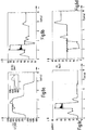
- Die Fig. 1a, 1b show two possible embodiments of such a drive solution with dissolved control edge.
- resolved control edges one understands technical language, in that each control edge of a conventional proportional directional control valve is released via at least one valve with at least one basic and / or one switching position. A valve with, for example, five control edges is thus replaceable over at least five switching valves.
- very small, temporally very fast-switching switching valves are used in the manner of 2/2-way switching valves (see. Fig. 1c ).
- the motor 10 is connected to a pressure supply source with the supply pressure p S and to a tank or return to the tank pressure p T.
- a full bridge is shown, which allows a four-quadrant operation.
- the system off Fig. 1b can only be operated in two quadrants, since the volume flow at both ports 14, 16 can only flow in one direction. Nevertheless, both circuits are suitable for control with resolved control edge, since in both cases, the volume flows at the terminals 14, 16 can be specified independently.
- the focus of the present invention is on the full bridge circuit Fig. 1 a and the Fig. 2 ,
- the presented design method is divided into two parts: a flatness-based follow-up control, which uses the volume flows as control variables and a lower-level control of the volume flow, which depends on the valve configuration. According to this division, the mathematical models for the drive 10 and the valve units 18, 20 are given below in detail.
- J is the rotor inertia
- dd is the coefficient of viscous friction
- ⁇ is the load torque
- p 1 and p 2 are the pressures at the engine ports 14, 16
- V M is the displacement of the engine.
- the load torque ⁇ is not understood as a system variable, but as a time-variant parameter, ie it is assumed that the controller design is known. In the absence of knowledge of the load torque, a load observer may be employed in the controller implementation.
- the volume flows entering the attenuation memories 12 are denoted by q A, 1 and q A, 2 , the leakage coefficient of the motor 10 by G.
- V i is the gas volumes of the memories 12
- p 0, i the bias pressures
- V 0, i the total volumes and n the polytropic exponent are the polytropic exponent.
- valve units 18 of the valve device 20 are described below from a control point of view closer. Since, as already mentioned at the beginning, the proposed approach to the design of a sequence control for different valve configurations is valid, two types of digital hydraulic full bridge circuit ( Fig. 1c, 2nd ) discussed by way of example. In both cases, the dynamics of valves 18 and valve solenoids are neglected.
- the supply pressure and the tank pressure are respectively denoted by p s and p t .
- the pressure-volume flow characteristics of the DFCUs are represented by the coefficient K DFCU .
- the switching indices ⁇ i, s , ⁇ i, t ⁇ ⁇ 0,1,2, ..., 2 m -1 ⁇ determine the switching state of the m-bit DFCUs.
- ⁇ i, s and ⁇ i, t designate the duty cycle of the respective valves 18 connected to the pressure or fluid supply and tank.
- the coefficient K PWM determines a linear approximation of the relationship between volume flow and duty cycle.
- the model of the drive presented above represents a non-linear multi-variable system.
- the control of such systems often exceeds the possibilities of simple PID controller. This applies in particular to the follow-up regulation.
- the so-called differential flatness is a system feature that facilitates not only the design of the controller but also the analysis and sizing of a system as well as the planning of suitable reference trajectories.
- differential flatness implies the existence of a so-called flat output.
- This (virtual) output is generally a function of system sizes and their time derivatives.
- a central feature of the flatness is that the trajectories of all system quantities, including the manipulated variables, are uniquely determined by the trajectories of the flat output, while these can in turn be freely specified. This implies that the desired system behavior can be given in the form of trajectories for the components of a flat output.
- the resulting control task is then limited to ensuring the trajectory sequence of the flat output, which in turn is facilitated by the fact that the manipulated variables can be calculated directly from the components of the flat output.
- the flatness property is also retained when the valve models according to the formulas (7) and (8) are taken into account, since the manipulated variables ⁇ i, s / t and ⁇ i, s / t directly from the volume flows q i and the pressures p i are calculated, which in turn can be calculated from the flat output y by means of formula (11).
- the flatness property is not limited exclusively to digital hydraulic drives, but can be transferred to all systems having the structure (6). This also applies to hydraulic linear drives such as differential cylinders, provided that the first component of the flat output y is replaced by the cylinder position.
- valve control is explained in more detail.
- the design of the flatness-based sequence control is based on three steps. First, suitable reference trajectories must be set for the flat output y. Subsequently, the control laws for the follow-up control are determined. Finally, the setpoint flows calculated by the slave controller are used as input for valve control.
- the pertinent valve control is as a functional block in the Fig. 3 represented there and (9), (10), since this function block is associated with the formulas (9) and (10) described above.
- the barrier p min can be used for the pressure cavitation (especially at Load changes) or to prevent the drop of the accumulator pressure below the biasing pressure p 0 .
- the reference of the lower of the two pressures p 1 (t) and p 2 (t) at any time p min Consequently, by a suitable compromise between pressure drop and bias pressure, the throttle losses can be reduced.
- This task involves two steps: First, the system is exactly linearized by a static feedback. This step again benefits from the flatness property in that it is always possible to exactly linearize a flat system by quasistatic feedback (cf. Delaleau, E .; Rudolph, J .: Control of flat systems by quasi-static feedback of generalized states. In: Int'l J. Control, Vol. 71 (1998), No. 5, pp. 745-765 ). It should be emphasized that the linearization by feedback in no way represents an approximation, but only a compensation of the nonlinearities. Since the resulting system is linear with respect to a new (virtual) input, a linear controller is sufficient to ensure the error dynamics.
- G 2 x 1 2 V M V M x 3 - J x 2 - d x 1 - ⁇
- the slave controller is described by equations (19) and (21) (cf. Fig. 3 ).
- the pertinent formulas for the respective function blocks are expressed in numbers and in brackets.
- the first function block 30 relates to the generation of trajectories.
- the second function block 32 symbolizes the controller or controller.
- the third functional block 34 refers to the linearizing feedback and the function block 36 is intended to relate to the estimator. Otherwise, the previously introduced reference quantities and reference numerals for the Fig. 3 used.
- an observer 36 can be used, which will be explained in more detail below.
- the controller design from the previous section is based on the knowledge of the load torque ⁇ . Such knowledge can be based either on a measurement or a very accurate knowledge of the underlying process. However, if these conditions are not met, an observer-based load estimate can be used.
- V ⁇ 2 be used to estimate both the angular velocity ⁇ and the load torque ⁇ .
- V ⁇ 1 V 0 p 0 1 n p 1 - 1 n - V ⁇ 1 .
- this error dynamics can easily be made asymptotically stable by choosing suitable observer gains l i, j . If the volume flows q 1 and q 2 are not known exactly, which is often the case in the application, the error dynamics are carried out non-autonomously with the errors q 1 and q 2 as excitation. This affects the usability of the estimator, especially in the case of digital hydraulic systems, in which the deviations by the switching operations of the valves 18 represent a highly dynamic excitation. Remedy can be provided by taking an additional measurement of the angular velocity w.
- a full bridge with 6-bit DFCUs ( Fig. 7 ) used as bridge resistors for driving.
- the DFCUs consist of modified HYDAC WS08W valves with switching times of 5 ms and downstream apertures with diameters of 0.45 mm, 0.62 mm, 0.9 mm, 1.28 mm, 1, 83 mm and 3 mm.
- the simulation models of the valves 18 form the mechanical valve piston dynamics, a simple magnetic model of the first order with saturation and a subordinate current control.
- the bridge resistors consist of valve groups 18 of the same type, driven by a 50 Hz PWM signal.
- the Redlich Kwong Soave provided by AMESim Gas model ( Soave, G .: Equilibrium constants from a modified Redlich-Kwong equation of state. In: Chem. Eng. Sci., Vol. 27 (1972), No. 6, pp. 1197-1203 ) was used to simulate the damping memory 12.
- the applied motor model 10 again corresponds to equation (1).
- the reference trajectory of the angular velocity w comprises three operating point changes.
- the engine 10 is accelerated from standstill to 900 min -1 , then braked to 100 min -1 and finally reversed to -600 min -1 .
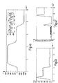
- the results of the simulation of the DFCU bridge are in the Fig. 4a, 4b, 4c represented, wherein in the x-direction, the time is plotted in seconds and in the Fig. 4a in y-direction, the angular velocity w with the unit 1 / min.
- the pressure in the unit bar is indicated in the y-direction.
- the curves are smoothed and, in particular, the jagged courses in the Fig. 4b and 4c are then smoothed out accordingly.
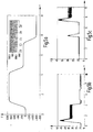
- the influence of the load estimator is through Fig. 6 clarified.
- the strongly fluctuating graphs refer to simulation values without load observers.
- the present invention relates to a flatness-based follow-up control for a digital hydraulic drive, based on the principle of the resolved control edge.
- the presented control strategies avoid the distinction of operating modes and the resulting switching between such modes.
- the additional degree of freedom associated with the second manipulated variable is used to set the minimum pressure at the motor terminals 14, 16. In this way, the emptying of the damping memory 12 and cavitation can be prevented. In addition, the pressure losses can be limited to the necessary minimum when using a variable supply.
- a load estimator is used as shown to determine the load torque ⁇ on the motor shaft of the constant velocity motor 10.
- n n polytropic [1] m Number of DFCU valves [1] p 1 , p 2 pressures [Pa] p 0.1 p 0.2 Memory boost pressures [Pa] p s , p t Supply, tank pressure [Pa] q 1 , q 2 Volume flows at the actuator connections [m 3 / s] q 1, A , q 2, A Storage volume flow [m 3 / s] V 1 , V 2 storage volume [m 3 ] V 0.1 , V 0.2 Total Speichervolumesn [m 3 ] V M Suction volume of the constant motor [m 3 ] v 1 , v 2 Feedback variables misc.
- x (x 1 , x 2 , x 3 ) T state variables misc.
- y (y 1 , y 2 ) T Flat outlet misc. ⁇ i, s / t PWM duty cycle [1] ⁇ i, s / t DFCU switching indexes [1] ⁇ load torque [Nm] ⁇ angular velocity [Rad / s]
Landscapes
- Engineering & Computer Science (AREA)
- Physics & Mathematics (AREA)
- Fluid Mechanics (AREA)
- Mechanical Engineering (AREA)
- General Engineering & Computer Science (AREA)
- Fluid-Pressure Circuits (AREA)
Claims (8)
- Système d'entraînement hydraulique numérique constitué de- un actionneur ainsi que- d'au moins un dispositif (20) de soupape, qui peut être actionné indépendamment, de commande des courants en volume dans les raccords (14, 16) d'entrée ou de sortie de l'actionneur,dans lequel un asservissement basé sur la platitude est utilisé et une commande subordonnée, qui dépend de la configuration du dispositif (20) de soupape vient en utilisation, caractérisé en ce que l'asservissement basé sur la platitude utilise les courants en volume comme grandeur de réglage et en ce que vient en utilisation, comme dispositif (20) de soupape à configurer, un circuit hydraulique numérique à pont complet en utilisant des unités (PW/M) de soupape modulées en largeur d'impulsion et/ou des unités (PCM) de soupape modulées en code d'impulsion et/ou des unités (DFCU) numériques de courant en volume.
- Système d'entraînement suivant la revendication 1, caractérisé en ce que, pour effectuer l'asservissement basé sur la platitude, on fixe d'abord des trajectoires de référence pour une sortie (y) plate, puis on détermine les lois de régulation pour l'asservissement et ensuite, on utilise les courants de consigne en volume calculés par un asservisseur, comme entrée pour la commande de la soupape.
- Système d'entraînement suivant la revendication 1 ou 2, caractérisé en ce que l'asservissement basé sur la platitude repose sur le principe du bord de commande résolu.
- Système d'entraînement suivant l'une des revendications précédentes, caractérisé en ce que l'actionneur est un moteur (10) à cylindrée constante et en ce que la commande du moteur (10) à cylindrée constante s'effectue dans le fonctionnement à quatre cadrans.
- Système d'entraînement suivant l'une des revendications précédentes, caractérisé en ce que le degré de liberté supplémentaire inhérent au principe du bord de commande résolu est utilisé pour commander, dans le courant de retour, la chute de pression sur la soupape respective du dispositif (20) de soupape.
- Système d'entraînement suivant l'une des revendications précédentes, caractérisé en ce que l'actionneur est un moteur (10) à cylindrée constante et en ce que la sortie (y) plate appartenant à la conception est définie à partir de la vitesse (ω) angulaire du moteur (10) à cylindrée constante comme actionneur et de la pression somme (P1 + P2) à ses raccords (14, 16) de moteur conduisant le fluide.
- Système d'entraînement suivant l'une des revendications précédentes, caractérisé en ce que la conception de l'asservisseur s'effectue sur la connaissance d'une grandeur de référence de charge ou en ce que l'on utilise à cet effet une évaluation de charge par un observateur.
- Système d'entraînement suivant l'une des revendications précédentes, caractérisé en ce que l'évaluation de charge s'effectue au moyen d'un observateur linéaire.
Applications Claiming Priority (1)
| Application Number | Priority Date | Filing Date | Title |
|---|---|---|---|
| DE102014003084.9A DE102014003084A1 (de) | 2014-03-01 | 2014-03-01 | Digitalhydraulisches Antriebssystem |
Publications (2)
| Publication Number | Publication Date |
|---|---|
| EP2933502A1 EP2933502A1 (fr) | 2015-10-21 |
| EP2933502B1 true EP2933502B1 (fr) | 2017-08-16 |
Family
ID=52473725
Family Applications (1)
| Application Number | Title | Priority Date | Filing Date |
|---|---|---|---|
| EP15000306.9A Active EP2933502B1 (fr) | 2014-03-01 | 2015-02-03 | Système d'entraînement hydraulique numérique |
Country Status (2)
| Country | Link |
|---|---|
| EP (1) | EP2933502B1 (fr) |
| DE (1) | DE102014003084A1 (fr) |
Families Citing this family (2)
| Publication number | Priority date | Publication date | Assignee | Title |
|---|---|---|---|---|
| DE102018217337A1 (de) * | 2018-10-10 | 2020-04-16 | Festo Se & Co. Kg | Bewegungsvorrichtung, Reifenhandhabungsvorrichtung und Verfahren zum Betrieb eines fluidischen Aktors |
| CN109441904B (zh) * | 2018-12-26 | 2020-07-14 | 燕山大学 | 一种数字阀组pwm与pcm复合控制装置及其控制方法 |
Family Cites Families (2)
| Publication number | Priority date | Publication date | Assignee | Title |
|---|---|---|---|---|
| DE102010021000A1 (de) * | 2010-05-12 | 2011-11-17 | Getrag Getriebe- Und Zahnradfabrik Hermann Hagenmeyer Gmbh & Cie Kg | Verfahren zur Ansteuerung einer Reibkupplung |
| DE102012006219A1 (de) * | 2012-03-27 | 2013-10-02 | Robert Bosch Gmbh | Verfahren und hydraulische Steueranordnung zur Ansteuerung eines Verbrauchers |
-
2014
- 2014-03-01 DE DE102014003084.9A patent/DE102014003084A1/de not_active Withdrawn
-
2015
- 2015-02-03 EP EP15000306.9A patent/EP2933502B1/fr active Active
Non-Patent Citations (1)
| Title |
|---|
| None * |
Also Published As
| Publication number | Publication date |
|---|---|
| DE102014003084A1 (de) | 2015-09-03 |
| EP2933502A1 (fr) | 2015-10-21 |
Similar Documents
| Publication | Publication Date | Title |
|---|---|---|
| DE3207392C2 (de) | Vorrichtung zur selbstanpassenden Stellungsregelung eines Stellgliedes | |
| EP2579112B1 (fr) | Dispositif de régulation | |
| EP0431287A1 (fr) | Procédé d'opération optimal de deux ou plusieurs compresseurs travaillant en parallèle ou en série | |
| DE102017213650A1 (de) | Verfahren zum Regeln eines hydraulischen Systems, Regeleinheit für ein hydraulisches System und hydraulisches System | |
| DE10261727A1 (de) | Steuersystem in Fuzzy-Logik für ein Rad eines Kraftfahrzeugs und Verfahren zum Implementieren einer Fuzzy-Logikeinheit für derartiges Rad eines Kraftfahrzeuges | |
| DE102005025590A1 (de) | Regelvorrichtung sowie Verfahren zum Betrieb einer Regelvorrichtung | |
| DE102011007083A1 (de) | Verfahren zum Steuern des Positionierens eines Aktuators mit einem Wellgetriebe | |
| EP0998700A2 (fr) | Procede pour la generation de trajectoires d'accostage, utilisable pour le guidage d'un vehicule vers une trajectoire cible predefinie | |
| EP2933502B1 (fr) | Système d'entraînement hydraulique numérique | |
| DE4342057A1 (de) | Verfahren zur Adaption der Regelparameter einer elektrohydraulischen Achse | |
| DE102019210003A1 (de) | Echtzeitfähige Trajektorienplanung für Axialkolbenpumpen in Schwenkscheibenbauweise unter systematischer Berücksichtigung von Systembeschränkungen | |
| EP2304515A1 (fr) | Système de commande comprenant une soupape de limitation de pression | |
| DE102016214708A1 (de) | Stetigventileinheit, hydraulische Achse und Verfahren zum Betreiben einer hydraulischen Achse | |
| DE102018206114A1 (de) | Verfahren zum Ansteuern eines Ventils und entsprechende Vorrichtung | |
| DE1523535C3 (de) | Selbstanpassender Regelkreis | |
| DE102018211738A1 (de) | Echtzeitfähige Ansteuerstrategie für hydraulische Systeme unter systematischer Berücksichtigung von Stell(raten)- und Zustandsgrößenbeschränkungen | |
| DE10034789B4 (de) | Verfahren und Vorrichtung zur Kompensation des nichtlinearen Verhaltens des Luftsystems einer Brennkraftmaschine | |
| DE19528253C2 (de) | Verfahren und Vorrichtung zur Vermeidung von Reglerinstabilitäten bei Pumpgrenzregelungen beim Betrieb von Strömungsmaschinen mit Reglern hoher Prportionalverstärkung | |
| DE102020213262A1 (de) | Verfahren zum Betreiben eines hydraulischen Antriebs | |
| DE602006000731T2 (de) | Autoadaptives Einstellungsgerät zur Positionssteuerung von Aktuatoren in einem Antriebssystem mittels Gleitmodusverfahren und entsprechendes Betriebsverfahren | |
| DE102009051514A1 (de) | Vorrichtung und Verfahren zur Druckregelung eines Volumens | |
| EP2171547A1 (fr) | Procédé et dispositif de réglage d'un dispositif de régulation | |
| EP3165801A1 (fr) | Procede et dispositif destines a la commande d'une electrovanne | |
| DE102008038484B4 (de) | Zustandsregelsystem zur Regelung einer Regelgröße einer Vorrichtung, insbesondere einer pneumatischen Schweißzange | |
| DE102008001311A1 (de) | Verfahren und Vorrichtung zum Betrieb eines Reglers, insbesondere zur Regelung einer Brennkraftmaschine |
Legal Events
| Date | Code | Title | Description |
|---|---|---|---|
| PUAI | Public reference made under article 153(3) epc to a published international application that has entered the european phase |
Free format text: ORIGINAL CODE: 0009012 |
|
| AK | Designated contracting states |
Kind code of ref document: A1 Designated state(s): AL AT BE BG CH CY CZ DE DK EE ES FI FR GB GR HR HU IE IS IT LI LT LU LV MC MK MT NL NO PL PT RO RS SE SI SK SM TR |
|
| AX | Request for extension of the european patent |
Extension state: BA ME |
|
| 17P | Request for examination filed |
Effective date: 20160316 |
|
| GRAP | Despatch of communication of intention to grant a patent |
Free format text: ORIGINAL CODE: EPIDOSNIGR1 |
|
| INTG | Intention to grant announced |
Effective date: 20170421 |
|
| GRAS | Grant fee paid |
Free format text: ORIGINAL CODE: EPIDOSNIGR3 |
|
| GRAA | (expected) grant |
Free format text: ORIGINAL CODE: 0009210 |
|
| AK | Designated contracting states |
Kind code of ref document: B1 Designated state(s): AL AT BE BG CH CY CZ DE DK EE ES FI FR GB GR HR HU IE IS IT LI LT LU LV MC MK MT NL NO PL PT RO RS SE SI SK SM TR |
|
| REG | Reference to a national code |
Ref country code: GB Ref legal event code: FG4D Free format text: NOT ENGLISH |
|
| REG | Reference to a national code |
Ref country code: CH Ref legal event code: EP |
|
| REG | Reference to a national code |
Ref country code: IE Ref legal event code: FG4D Free format text: LANGUAGE OF EP DOCUMENT: GERMAN |
|
| REG | Reference to a national code |
Ref country code: AT Ref legal event code: REF Ref document number: 919350 Country of ref document: AT Kind code of ref document: T Effective date: 20170915 |
|
| REG | Reference to a national code |
Ref country code: DE Ref legal event code: R096 Ref document number: 502015001645 Country of ref document: DE |
|
| REG | Reference to a national code |
Ref country code: SE Ref legal event code: TRGR |
|
| REG | Reference to a national code |
Ref country code: NL Ref legal event code: MP Effective date: 20170816 |
|
| REG | Reference to a national code |
Ref country code: LT Ref legal event code: MG4D |
|
| REG | Reference to a national code |
Ref country code: FR Ref legal event code: PLFP Year of fee payment: 4 |
|
| PG25 | Lapsed in a contracting state [announced via postgrant information from national office to epo] |
Ref country code: NO Free format text: LAPSE BECAUSE OF FAILURE TO SUBMIT A TRANSLATION OF THE DESCRIPTION OR TO PAY THE FEE WITHIN THE PRESCRIBED TIME-LIMIT Effective date: 20171116 Ref country code: LT Free format text: LAPSE BECAUSE OF FAILURE TO SUBMIT A TRANSLATION OF THE DESCRIPTION OR TO PAY THE FEE WITHIN THE PRESCRIBED TIME-LIMIT Effective date: 20170816 Ref country code: NL Free format text: LAPSE BECAUSE OF FAILURE TO SUBMIT A TRANSLATION OF THE DESCRIPTION OR TO PAY THE FEE WITHIN THE PRESCRIBED TIME-LIMIT Effective date: 20170816 |
|
| PG25 | Lapsed in a contracting state [announced via postgrant information from national office to epo] |
Ref country code: PL Free format text: LAPSE BECAUSE OF FAILURE TO SUBMIT A TRANSLATION OF THE DESCRIPTION OR TO PAY THE FEE WITHIN THE PRESCRIBED TIME-LIMIT Effective date: 20170816 Ref country code: GR Free format text: LAPSE BECAUSE OF FAILURE TO SUBMIT A TRANSLATION OF THE DESCRIPTION OR TO PAY THE FEE WITHIN THE PRESCRIBED TIME-LIMIT Effective date: 20171117 Ref country code: LV Free format text: LAPSE BECAUSE OF FAILURE TO SUBMIT A TRANSLATION OF THE DESCRIPTION OR TO PAY THE FEE WITHIN THE PRESCRIBED TIME-LIMIT Effective date: 20170816 Ref country code: BG Free format text: LAPSE BECAUSE OF FAILURE TO SUBMIT A TRANSLATION OF THE DESCRIPTION OR TO PAY THE FEE WITHIN THE PRESCRIBED TIME-LIMIT Effective date: 20171116 Ref country code: IS Free format text: LAPSE BECAUSE OF FAILURE TO SUBMIT A TRANSLATION OF THE DESCRIPTION OR TO PAY THE FEE WITHIN THE PRESCRIBED TIME-LIMIT Effective date: 20171216 Ref country code: RS Free format text: LAPSE BECAUSE OF FAILURE TO SUBMIT A TRANSLATION OF THE DESCRIPTION OR TO PAY THE FEE WITHIN THE PRESCRIBED TIME-LIMIT Effective date: 20170816 Ref country code: ES Free format text: LAPSE BECAUSE OF FAILURE TO SUBMIT A TRANSLATION OF THE DESCRIPTION OR TO PAY THE FEE WITHIN THE PRESCRIBED TIME-LIMIT Effective date: 20170816 |
|
| PG25 | Lapsed in a contracting state [announced via postgrant information from national office to epo] |
Ref country code: RO Free format text: LAPSE BECAUSE OF FAILURE TO SUBMIT A TRANSLATION OF THE DESCRIPTION OR TO PAY THE FEE WITHIN THE PRESCRIBED TIME-LIMIT Effective date: 20170816 Ref country code: DK Free format text: LAPSE BECAUSE OF FAILURE TO SUBMIT A TRANSLATION OF THE DESCRIPTION OR TO PAY THE FEE WITHIN THE PRESCRIBED TIME-LIMIT Effective date: 20170816 Ref country code: CZ Free format text: LAPSE BECAUSE OF FAILURE TO SUBMIT A TRANSLATION OF THE DESCRIPTION OR TO PAY THE FEE WITHIN THE PRESCRIBED TIME-LIMIT Effective date: 20170816 |
|
| REG | Reference to a national code |
Ref country code: DE Ref legal event code: R097 Ref document number: 502015001645 Country of ref document: DE |
|
| PG25 | Lapsed in a contracting state [announced via postgrant information from national office to epo] |
Ref country code: SK Free format text: LAPSE BECAUSE OF FAILURE TO SUBMIT A TRANSLATION OF THE DESCRIPTION OR TO PAY THE FEE WITHIN THE PRESCRIBED TIME-LIMIT Effective date: 20170816 Ref country code: SM Free format text: LAPSE BECAUSE OF FAILURE TO SUBMIT A TRANSLATION OF THE DESCRIPTION OR TO PAY THE FEE WITHIN THE PRESCRIBED TIME-LIMIT Effective date: 20170816 Ref country code: EE Free format text: LAPSE BECAUSE OF FAILURE TO SUBMIT A TRANSLATION OF THE DESCRIPTION OR TO PAY THE FEE WITHIN THE PRESCRIBED TIME-LIMIT Effective date: 20170816 |
|
| PLBE | No opposition filed within time limit |
Free format text: ORIGINAL CODE: 0009261 |
|
| STAA | Information on the status of an ep patent application or granted ep patent |
Free format text: STATUS: NO OPPOSITION FILED WITHIN TIME LIMIT |
|
| 26N | No opposition filed |
Effective date: 20180517 |
|
| PG25 | Lapsed in a contracting state [announced via postgrant information from national office to epo] |
Ref country code: SI Free format text: LAPSE BECAUSE OF FAILURE TO SUBMIT A TRANSLATION OF THE DESCRIPTION OR TO PAY THE FEE WITHIN THE PRESCRIBED TIME-LIMIT Effective date: 20170816 |
|
| REG | Reference to a national code |
Ref country code: CH Ref legal event code: PL |
|
| PG25 | Lapsed in a contracting state [announced via postgrant information from national office to epo] |
Ref country code: MC Free format text: LAPSE BECAUSE OF FAILURE TO SUBMIT A TRANSLATION OF THE DESCRIPTION OR TO PAY THE FEE WITHIN THE PRESCRIBED TIME-LIMIT Effective date: 20170816 Ref country code: MT Free format text: LAPSE BECAUSE OF FAILURE TO SUBMIT A TRANSLATION OF THE DESCRIPTION OR TO PAY THE FEE WITHIN THE PRESCRIBED TIME-LIMIT Effective date: 20170816 |
|
| REG | Reference to a national code |
Ref country code: IE Ref legal event code: MM4A |
|
| REG | Reference to a national code |
Ref country code: BE Ref legal event code: MM Effective date: 20180228 |
|
| PG25 | Lapsed in a contracting state [announced via postgrant information from national office to epo] |
Ref country code: LU Free format text: LAPSE BECAUSE OF NON-PAYMENT OF DUE FEES Effective date: 20180203 Ref country code: CH Free format text: LAPSE BECAUSE OF NON-PAYMENT OF DUE FEES Effective date: 20180228 Ref country code: LI Free format text: LAPSE BECAUSE OF NON-PAYMENT OF DUE FEES Effective date: 20180228 |
|
| PG25 | Lapsed in a contracting state [announced via postgrant information from national office to epo] |
Ref country code: IE Free format text: LAPSE BECAUSE OF NON-PAYMENT OF DUE FEES Effective date: 20180203 |
|
| PG25 | Lapsed in a contracting state [announced via postgrant information from national office to epo] |
Ref country code: BE Free format text: LAPSE BECAUSE OF NON-PAYMENT OF DUE FEES Effective date: 20180228 |
|
| PG25 | Lapsed in a contracting state [announced via postgrant information from national office to epo] |
Ref country code: TR Free format text: LAPSE BECAUSE OF FAILURE TO SUBMIT A TRANSLATION OF THE DESCRIPTION OR TO PAY THE FEE WITHIN THE PRESCRIBED TIME-LIMIT Effective date: 20170816 |
|
| PG25 | Lapsed in a contracting state [announced via postgrant information from national office to epo] |
Ref country code: PT Free format text: LAPSE BECAUSE OF FAILURE TO SUBMIT A TRANSLATION OF THE DESCRIPTION OR TO PAY THE FEE WITHIN THE PRESCRIBED TIME-LIMIT Effective date: 20170816 |
|
| PG25 | Lapsed in a contracting state [announced via postgrant information from national office to epo] |
Ref country code: MK Free format text: LAPSE BECAUSE OF NON-PAYMENT OF DUE FEES Effective date: 20170816 Ref country code: HR Free format text: LAPSE BECAUSE OF FAILURE TO SUBMIT A TRANSLATION OF THE DESCRIPTION OR TO PAY THE FEE WITHIN THE PRESCRIBED TIME-LIMIT Effective date: 20170816 Ref country code: CY Free format text: LAPSE BECAUSE OF FAILURE TO SUBMIT A TRANSLATION OF THE DESCRIPTION OR TO PAY THE FEE WITHIN THE PRESCRIBED TIME-LIMIT Effective date: 20170816 Ref country code: HU Free format text: LAPSE BECAUSE OF FAILURE TO SUBMIT A TRANSLATION OF THE DESCRIPTION OR TO PAY THE FEE WITHIN THE PRESCRIBED TIME-LIMIT; INVALID AB INITIO Effective date: 20150203 |
|
| PG25 | Lapsed in a contracting state [announced via postgrant information from national office to epo] |
Ref country code: AL Free format text: LAPSE BECAUSE OF FAILURE TO SUBMIT A TRANSLATION OF THE DESCRIPTION OR TO PAY THE FEE WITHIN THE PRESCRIBED TIME-LIMIT Effective date: 20170816 |
|
| REG | Reference to a national code |
Ref country code: AT Ref legal event code: MM01 Ref document number: 919350 Country of ref document: AT Kind code of ref document: T Effective date: 20200203 |
|
| PG25 | Lapsed in a contracting state [announced via postgrant information from national office to epo] |
Ref country code: AT Free format text: LAPSE BECAUSE OF NON-PAYMENT OF DUE FEES Effective date: 20200203 |
|
| PGFP | Annual fee paid to national office [announced via postgrant information from national office to epo] |
Ref country code: FI Payment date: 20230120 Year of fee payment: 9 |
|
| PGFP | Annual fee paid to national office [announced via postgrant information from national office to epo] |
Ref country code: IT Payment date: 20230207 Year of fee payment: 9 Ref country code: DE Payment date: 20230228 Year of fee payment: 9 |
|
| PGFP | Annual fee paid to national office [announced via postgrant information from national office to epo] |
Ref country code: GB Payment date: 20231220 Year of fee payment: 10 |
|
| PGFP | Annual fee paid to national office [announced via postgrant information from national office to epo] |
Ref country code: SE Payment date: 20231214 Year of fee payment: 10 Ref country code: FR Payment date: 20231221 Year of fee payment: 10 |