EP2933397A2 - Profil de liaison et panneau de construction préfabriqué à utiliser dans les cloisons sèches - Google Patents
Profil de liaison et panneau de construction préfabriqué à utiliser dans les cloisons sèches Download PDFInfo
- Publication number
- EP2933397A2 EP2933397A2 EP15162713.0A EP15162713A EP2933397A2 EP 2933397 A2 EP2933397 A2 EP 2933397A2 EP 15162713 A EP15162713 A EP 15162713A EP 2933397 A2 EP2933397 A2 EP 2933397A2
- Authority
- EP
- European Patent Office
- Prior art keywords
- recess
- stabilizer bar
- building board
- latching means
- stabilizing
- Prior art date
- Legal status (The legal status is an assumption and is not a legal conclusion. Google has not performed a legal analysis and makes no representation as to the accuracy of the status listed.)
- Granted
Links
- 230000000087 stabilizing effect Effects 0.000 claims abstract description 37
- 238000010276 construction Methods 0.000 claims abstract description 13
- 239000003381 stabilizer Substances 0.000 claims description 47
- 238000003780 insertion Methods 0.000 claims description 23
- 230000037431 insertion Effects 0.000 claims description 23
- 238000005452 bending Methods 0.000 claims description 21
- 238000000034 method Methods 0.000 claims description 9
- 238000004519 manufacturing process Methods 0.000 claims description 6
- 239000000853 adhesive Substances 0.000 claims description 2
- 230000001070 adhesive effect Effects 0.000 claims description 2
- 238000003754 machining Methods 0.000 claims description 2
- 230000000149 penetrating effect Effects 0.000 claims 1
- 239000010410 layer Substances 0.000 description 25
- 239000002390 adhesive tape Substances 0.000 description 3
- 238000001125 extrusion Methods 0.000 description 2
- 230000001154 acute effect Effects 0.000 description 1
- 238000005253 cladding Methods 0.000 description 1
- 239000012792 core layer Substances 0.000 description 1
- 238000005034 decoration Methods 0.000 description 1
- 230000001419 dependent effect Effects 0.000 description 1
- 229910052602 gypsum Inorganic materials 0.000 description 1
- 239000010440 gypsum Substances 0.000 description 1
- 238000009434 installation Methods 0.000 description 1
- 238000002360 preparation method Methods 0.000 description 1
- 238000004321 preservation Methods 0.000 description 1
- 230000003313 weakening effect Effects 0.000 description 1
Images


Classifications
-
- E—FIXED CONSTRUCTIONS
- E04—BUILDING
- E04F—FINISHING WORK ON BUILDINGS, e.g. STAIRS, FLOORS
- E04F19/00—Other details of constructional parts for finishing work on buildings
- E04F19/02—Borders; Finishing strips, e.g. beadings; Light coves
- E04F19/06—Borders; Finishing strips, e.g. beadings; Light coves specially designed for securing panels or masking the edges of wall- or floor-covering elements
- E04F19/062—Borders; Finishing strips, e.g. beadings; Light coves specially designed for securing panels or masking the edges of wall- or floor-covering elements used between similar elements
- E04F19/064—Borders; Finishing strips, e.g. beadings; Light coves specially designed for securing panels or masking the edges of wall- or floor-covering elements used between similar elements in corners
-
- E—FIXED CONSTRUCTIONS
- E04—BUILDING
- E04C—STRUCTURAL ELEMENTS; BUILDING MATERIALS
- E04C2/00—Building elements of relatively thin form for the construction of parts of buildings, e.g. sheet materials, slabs, or panels
- E04C2/02—Building elements of relatively thin form for the construction of parts of buildings, e.g. sheet materials, slabs, or panels characterised by specified materials
- E04C2/04—Building elements of relatively thin form for the construction of parts of buildings, e.g. sheet materials, slabs, or panels characterised by specified materials of concrete or other stone-like material; of asbestos cement; of cement and other mineral fibres
- E04C2/043—Building elements of relatively thin form for the construction of parts of buildings, e.g. sheet materials, slabs, or panels characterised by specified materials of concrete or other stone-like material; of asbestos cement; of cement and other mineral fibres of plaster
-
- E—FIXED CONSTRUCTIONS
- E04—BUILDING
- E04C—STRUCTURAL ELEMENTS; BUILDING MATERIALS
- E04C2/00—Building elements of relatively thin form for the construction of parts of buildings, e.g. sheet materials, slabs, or panels
- E04C2/30—Building elements of relatively thin form for the construction of parts of buildings, e.g. sheet materials, slabs, or panels characterised by the shape or structure
- E04C2/32—Building elements of relatively thin form for the construction of parts of buildings, e.g. sheet materials, slabs, or panels characterised by the shape or structure formed of corrugated or otherwise indented sheet-like material; composed of such layers with or without layers of flat sheet-like material
- E04C2/328—Building elements of relatively thin form for the construction of parts of buildings, e.g. sheet materials, slabs, or panels characterised by the shape or structure formed of corrugated or otherwise indented sheet-like material; composed of such layers with or without layers of flat sheet-like material slightly bowed or folded panels not otherwise provided for
-
- E—FIXED CONSTRUCTIONS
- E04—BUILDING
- E04F—FINISHING WORK ON BUILDINGS, e.g. STAIRS, FLOORS
- E04F19/00—Other details of constructional parts for finishing work on buildings
- E04F19/02—Borders; Finishing strips, e.g. beadings; Light coves
- E04F19/06—Borders; Finishing strips, e.g. beadings; Light coves specially designed for securing panels or masking the edges of wall- or floor-covering elements
- E04F19/062—Borders; Finishing strips, e.g. beadings; Light coves specially designed for securing panels or masking the edges of wall- or floor-covering elements used between similar elements
-
- E—FIXED CONSTRUCTIONS
- E04—BUILDING
- E04B—GENERAL BUILDING CONSTRUCTIONS; WALLS, e.g. PARTITIONS; ROOFS; FLOORS; CEILINGS; INSULATION OR OTHER PROTECTION OF BUILDINGS
- E04B2/00—Walls, e.g. partitions, for buildings; Wall construction with regard to insulation; Connections specially adapted to walls
- E04B2/72—Non-load-bearing walls of elements of relatively thin form with respect to the thickness of the wall
- E04B2/723—Non-load-bearing walls of elements of relatively thin form with respect to the thickness of the wall constituted of gypsum elements
- E04B2002/725—Corner or angle connection details
-
- E—FIXED CONSTRUCTIONS
- E04—BUILDING
- E04F—FINISHING WORK ON BUILDINGS, e.g. STAIRS, FLOORS
- E04F13/00—Coverings or linings, e.g. for walls or ceilings
- E04F13/07—Coverings or linings, e.g. for walls or ceilings composed of covering or lining elements; Sub-structures therefor; Fastening means therefor
- E04F13/08—Coverings or linings, e.g. for walls or ceilings composed of covering or lining elements; Sub-structures therefor; Fastening means therefor composed of a plurality of similar covering or lining elements
- E04F13/14—Coverings or linings, e.g. for walls or ceilings composed of covering or lining elements; Sub-structures therefor; Fastening means therefor composed of a plurality of similar covering or lining elements stone or stone-like materials, e.g. ceramics concrete; of glass or with an outer layer of stone or stone-like materials or glass
-
- E—FIXED CONSTRUCTIONS
- E04—BUILDING
- E04F—FINISHING WORK ON BUILDINGS, e.g. STAIRS, FLOORS
- E04F13/00—Coverings or linings, e.g. for walls or ceilings
- E04F13/02—Coverings or linings, e.g. for walls or ceilings of plastic materials hardening after applying, e.g. plaster
- E04F13/04—Bases for plaster
- E04F13/06—Edge-protecting borders
- E04F2013/063—Edge-protecting borders for corners
-
- E—FIXED CONSTRUCTIONS
- E05—LOCKS; KEYS; WINDOW OR DOOR FITTINGS; SAFES
- E05D—HINGES OR SUSPENSION DEVICES FOR DOORS, WINDOWS OR WINGS
- E05D1/00—Pinless hinges; Substitutes for hinges
- E05D1/02—Pinless hinges; Substitutes for hinges made of one piece
Definitions
- the invention relates to a prefabricated building element for the realization of room corners in drywall and a kareries connection profile, wherein two structural panels of the prefabricated building element from the plane to the rear are hinged.
- a disadvantage of such an embodiment is that the correspondingly used profile at the corner of the end faces of the two adjacent building panels is visible across. However, deviating from the structural panels surface property of the visible profile in the corner considerably complicates the subsequent decoration of the building panels.
- a solution is known from the prior art, in which a recess is incorporated in a continuous building board, so that the arranged on the visible side cover layer is maintained.
- a double-sided adhesive tape is inserted, wherein after flaps of the both sides of the recess existing building board sections by means of the double-sided adhesive tape in the corner a renewed connection of the two building board sections is created.
- a disadvantage of the latter embodiment is the lack of stability of the provided with a recess building board, despite the use the double-sided adhesive tape. This can lead to damage in the handling of the building board before it is installed at the place of use.
- the cover layer can tear in the region of the recess in the event of uneven lifting. Furthermore, it can come by lifting on a Bauplattenabêt to detach the top layer from Bauplattenkern. Not to be neglected is the risk of an impermissible breaking out of the construction board core adjacent to the recess.
- plasterboard occurs almost inevitably an irregularly shaped breaking off the bottom of the recess towards tapered gypsum core.
- Object of the present invention is therefore to provide a connection profile and a finished component with a corresponding connection profile available, which overcomes the disadvantages of the previous embodiments.
- the generic finished component is initially used for the realization of room corners in drywall.
- it first requires a building board, which has a arranged on the visible side continuous cover layer and behind the cover layer facing a rear plate core.
- the plate core is divided by the recess.
- the divided required building board in a right building panel section and a left building board section in continuous cover layer forms a bending zone, which allows a folding of the right building board section relative to the left building board section at least towards the rear over an angle of at least 90 °.
- the prefabricated component comprises a right stabilizer bar for attachment to the right structural plate section and a left stabilizer bar for attachment to the left structural plate section, wherein the stabilizer bars are arranged within the recess. It is obvious that, taking into account the shape and size of the recess, the stabilizer bar must be shaped such that unimpeded flaps of Bauplattenabête back is possible.
- the respective structural panel sections are provided with an insertion groove extending from the recess and extending parallel to the respective structural panel section.
- the stabilizing strips each have a Einsteckschenkel, which is secured in the insertion of the respective Bauplattenabitess.
- a particularly advantageous prefabricated component is created when a plasterboard is used as a building board, in which embodiment the corresponding cover layer is formed by a paper layer.
- the stabilizing strips have a height which is less than the thickness of the intended building board less the thickness of the cover layer.
- the stabilizing strips between the cover layer and the back of the building board can be arranged, whereby a particularly advantageous and damage-free transportability of the finished component is achieved.
- the finished component can be layered without the risk of damage to each other.
- the shape and the preparation of the stabilizing strips further simplified if they are designed substantially symmetrical to each other. This simplifies in particular the design of the recess in the building board as well as the insertion grooves in the building board sections.
- the two stabilizing strips in contrast, it is particularly advantageous if the right and left stabilizing strips are designed as identical parts.
- An advantageous assembly as well as an advantageous usability of the finished component is achieved when the building board sections are mutually hinged at an angle of at least 170 ° to the visible side.
- the two insertion grooves of the respective structural panel sections come to lie largely parallel to one another. In this mounting position can easily Stabilizing strips are attached to a prepared building board by inserting the Einsteckschenkel in the Einstecknuten.
- the stabilizing strips are extended by a latching function.
- the right stabilizer bar right latching means and the left stabilizer left latching means the embodiment of the latching means is initially insignificant, provided that it is ensured that the flaps of the Bauplattenabterrorisme by 90 ° to the rear latching the right latching means with the left latching means ,
- This particularly advantageous embodiment with a latching function ensures that at the place of use, starting from the planar shape of the finished component a structural panel section can be folded so that the 90 ° angled shape of the finished component results, then no further adherence to the preservation of this angled shape is required. Now, the finished component can be easily attached to the place of use, the angle is already held automatically due to the locking.
- the realization of the locking means can in this case take place in various ways, wherein in a first particularly advantageous embodiment of the stabilizing strips - particularly advantageously produced as extruded profiles or as a common extrusion profile - the right locking means by means of a locking lug engages behind the left locking means (where right and left are chosen purely arbitrarily).
- the stabilizer bars can be prepared in addition to the locking means in the extruded profile without additional rework and are therefore particularly cost feasible.
- Conceivable here is an embodiment similar to a zipper, so that when the fastening sections are folded by 90 ° to the rear, hooking of the locking means to one another is effected.
- the realizable locking force it is also particularly advantageous if it is not too high. Rather, it is particularly advantageous if a disengagement occurs before a critical breaking load is reached. If unfavorable handling is performed on the prefabricated component after locking, however, it is advantageous if disengagement takes place. If, for example, only one structural panel section is detected and in the other structural panel section, bending forces occur, for example, in a horizontal position under its own weight, then these bending forces can quickly lead to breakage of the structural panel section, in particular in the case of a plasterboard panel. Particularly at risk in this case is the area directly at the insertion groove. In contrast, it is advantageous if, instead, a disengagement takes place, so that although not held Bauplattenabites immediately abruptly drops, but there is a realistic possibility that in a free swinging down in the air damage due to the disengagement is prevented.
- the stabilizer bars can be realized in a particularly advantageous manner by an inventive connection profile.
- the one-piece connection profile initially has, generically, a right stabilizer bar for attachment to a right-hand structural panel section and a left stabilizer bar for attachment to a left-hand structural panel section, the stabilizer bars being fastened as intended in the recess of the structural panel.
- the respective stabilizing strips are extended by a Einsteckschenkel, by means of which a significantly improved connection with the respective Bauplattenabrough is achieved without the need for gripping the end faces of the structural panels sections.
- the Einsteckschenkel extends parallel to the plane of the respective Bauplattenabitess, wherein correspondingly in the respective Bauplattenabsacrificing an outgoing of the recess insertion groove is required, which must extend parallel to the corresponding plane of the corresponding Bauplattenabitess.
- connection profile can be used in a particularly advantageous manner in a prefabricated component as described above.
- connection profile comprises a central bending section connecting the stabilizing strips.
- connection profile for realizing a bend of the right stabilizer bar relative to the left stabilizer bar by 90 ° to the back is achieved when the connection profile in the initial state has a V-shaped from the bending section to the back opening shape. Furthermore, it is advantageous if the connection profile has on both sides of the bending section a substantially triangular-shaped base section and a plate-shaped web section following thereon.
- the connection profile without viewing the Einsteckschenkel in the starting position is Y-shaped, whereby it can be inserted into a corresponding Y-shaped recess in the building board. This shape favors on the one hand the processing of the building board for the production of the recess.
- novel prefabricated component further leads to a novel method according to the invention for producing a prefabricated component for the realization of room corners in dry construction.
- a building board which has a arranged on the visible side continuous cover layer and a behind the cover layer facing a back plate core. Furthermore, a connection profile with a right and a left stabilizer bar or separate stabilizer bars are needed, each having a Einsteckschenkel.
- a processing of the building board is required, in which the plate core is severed to the top layer in a straight line over the length of the building board.
- this can be done by a separating cut through the plate core, or in a second type of process to form a plate-core removing V- or Y-shaped recess.
- a right and a left adjacent to the recess part plate is formed, wherein the two partial plates remain connected to each other by the continuous cover layer of the building board.
- connection profile is used in a particularly advantageous manner, which integrally has a central bending section, in the particularly advantageous method, the connection profile is folded to the visible side before mounting on the building board sections, so that the Einsteckschenkel are arranged parallel to each other.
- both Einsteckschenkel the connection profile can be inserted simultaneously into the two Einstecknuten the two structural panels sections.
- both sub-plates together in the region of the machining tool on a abut flat support.
- the support it is advantageous to carry out the support with a length of at least 50 mm, particularly advantageously of at least 200 mm, and at a height of at least 120% of the depth of the insertion grooves, particularly advantageously of at least 200% of the depth of the insertion grooves.
- connection profiles and for prefabricated components are outlined.
- connection profile 01 is sketched in cross section, with this with a Y-shaped basic shape divides into a right stabilizer bar 04r and a left stabilizer bar 041, which 04r, 041 are connected to each other via a bending portion 03.
- the bending portion 03 is selected to be so thin that this 03 realizes a film hinge, based on which 03, the two stabilizing strips 04r, 041 are mutually bendable.
- the V-shaped opening towards the rear of the connection profile 01 ensures that the two stabilizing strips 04r, 041 are bendable towards each other by 90 ° towards the rear.
- the design of the stabilizing strips 04 which are each composed of a triangular base section 05, a plate-shaped web section 06 adjoining thereto, and a plug-in leg 07, which extends substantially parallel to the plane of the respective building board section 16, can also be seen.
- FIG. 2 is a finished component 11 with the connection profile 01 from Fig. 1 sketched, with the associated building board 15 in the FIG. 3 is pictured.
- 161 161 insertion grooves 19 are parallel to the plane of the respective structural panel sections incorporated, in which 19 the Einsteckschenkel 07 of the connection profile 01 are attached.
- the connection profile 01 with the building board 15 is achieved.
- connection profile 01 is completely within the recess 18 in this particularly advantageous design and does not protrude beyond the back 13 of the building board 15.
- the finished component 11 is sketched in its use position, for which purpose the two structural panels 16r, 161 of the building panel 15 are folded over by an angle of 90 ° to the rear side 13 out. Accordingly, the two web portions 06 of the right stabilizer bar 04r and the left stabilizer bar 041 come to rest in parallel. Furthermore, it can be seen the advantageous corner design of the finished component in the folded position by 90 °, which is largely acute angle due to the bending region 03 in the manner of a film hinge. Furthermore, it can be seen from this embodiment that in use a uniform surface is created circumferentially around the corner, so that the subsequent surface design can be made without reworking or additional effort.
- connection profile 01 into the building board 15 comprising the two building board sections 16r and 161 is particularly simple if the connection profile 01 and the building board 15 are each folded through 180 ° to the visible side 12 towards each other (see FIG. 5 ).
- the connection profile 01 and the building board 15 are each folded through 180 ° to the visible side 12 towards each other (see FIG. 5 ).
- the two Einsteckschenkel 07 parallel to each other to lie.
- the two structural plate sections 16r and 161 can be bent by 180 ° to each other to the visible side, so that their Einstecknuten 19 are also aligned parallel to each other to the front side open. In this position, the assembly of the connection profile 01 is readily possible on the thus prepared building board 15.
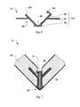
- FIG. 6 is an alternative to execution Fig. 1 sketched a connection profile 21 with locking function, which 21 as well as the profile Fig. 1 can be produced by extrusion.
- a stabilizing bar 24r now has a first locking means 29r in the form of a latching hook.
- the other stabilizer bar 24 forms with the free end face of the regularly present web section 06, a second latching means 291, which 291 can be engaged behind by the latching hook 29r.
- connection profile 21 Fig. 6 folded in use in a prefabricated component 31 in the functional position by 90 ° to the back 13.
- the position of the two structural plate sections 16r, 161 is reliably held relative to one another.
- the detent function requires a slight further recess in the associated building board 35.
- connection profile 41 is sketched with locking function, now the right stabilizer bar 44r and the left stabilizer bar 441 are constructed similar, with each undercut changing grid surveys 49r and 491 quasi zipper hooked into each other and thus also secure the position of the two stabilizing bars 44r, 441 to each other.
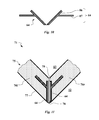
- stabilizer bars 64 are outlined, which 64 for the right side and the left side as equal parts be executed. These 64 are each composed of a web portion 06 and a Einsteckschenkel 07 together.
- FIG. 11 This outlines the FIG. 11 a prefabricated component 71 with the separate stabilizing strips 64 corresponding to the previous figure.
- the folding of the right structural plate section 76r relative to the left structural plate section 761 takes place at the covering layer 77 passing through in the region of the recess 78.
- With larger plate thicknesses of the structural plate 75 it is possible to limit the processing in the region of the recess 78 to that region in which the stabilizing strips 64 are attached, so that the rear side above the stabilizing strips 64, a shoulder 79 is formed on the structural plate sections 76.
Landscapes
- Engineering & Computer Science (AREA)
- Architecture (AREA)
- Civil Engineering (AREA)
- Structural Engineering (AREA)
- Finishing Walls (AREA)
- Roof Covering Using Slabs Or Stiff Sheets (AREA)
- Panels For Use In Building Construction (AREA)
- Revetment (AREA)
Priority Applications (3)
| Application Number | Priority Date | Filing Date | Title |
|---|---|---|---|
| PL15162713T PL2933397T3 (pl) | 2014-04-16 | 2015-04-08 | Profil łączący i prefabrykowana płyta budowlana do zastosowania w suchej zabudowie |
| SI201530081T SI2933397T1 (sl) | 2014-04-16 | 2015-04-08 | Vezni profil in montažna plošča za uporabo pri suhi gradnji |
| HRP20171271TT HRP20171271T1 (hr) | 2014-04-16 | 2017-08-18 | Spojni profil i predfabricirana građevna ploča za uporabu u sustavu suhe gradnje |
Applications Claiming Priority (1)
| Application Number | Priority Date | Filing Date | Title |
|---|---|---|---|
| DE202014101817.4U DE202014101817U1 (de) | 2014-04-16 | 2014-04-16 | Verbindungsprofil und Fertigbauplatte zur Verwendung im Trockenbau |
Publications (4)
| Publication Number | Publication Date |
|---|---|
| EP2933397A2 true EP2933397A2 (fr) | 2015-10-21 |
| EP2933397A3 EP2933397A3 (fr) | 2015-11-11 |
| EP2933397B1 EP2933397B1 (fr) | 2017-05-31 |
| EP2933397B8 EP2933397B8 (fr) | 2017-11-01 |
Family
ID=50726533
Family Applications (1)
| Application Number | Title | Priority Date | Filing Date |
|---|---|---|---|
| EP15162713.0A Active EP2933397B8 (fr) | 2014-04-16 | 2015-04-08 | Profil de liaison et panneau de construction préfabriqué à utiliser dans les cloisons sèches |
Country Status (8)
| Country | Link |
|---|---|
| EP (1) | EP2933397B8 (fr) |
| DE (1) | DE202014101817U1 (fr) |
| DK (1) | DK2933397T3 (fr) |
| ES (1) | ES2638202T3 (fr) |
| HR (1) | HRP20171271T1 (fr) |
| LT (1) | LT2933397T (fr) |
| PL (1) | PL2933397T3 (fr) |
| SI (1) | SI2933397T1 (fr) |
Cited By (2)
| Publication number | Priority date | Publication date | Assignee | Title |
|---|---|---|---|---|
| WO2018049505A1 (fr) * | 2016-09-15 | 2018-03-22 | Jerry Moscovitch | Appareil et procédé de cloison sèche articulée |
| EP3599317A1 (fr) * | 2018-07-24 | 2020-01-29 | Schmitt Verwaltungs GmbH | Élément préfabriqué destiné à la réalisation d'angles de pièce dans une construction sèche |
Family Cites Families (3)
| Publication number | Priority date | Publication date | Assignee | Title |
|---|---|---|---|---|
| DE3141709A1 (de) * | 1981-10-21 | 1983-05-05 | Oskar 6620 Völklingen Adam | "abgewinkeltes formteil aus plattfoermigem gegenstand" |
| DE3514276A1 (de) * | 1985-04-17 | 1986-10-23 | VS Winter Bankeinrichtungen GmbH, 4950 Minden | Scharnierverbindung fuer extruderprofile |
| AUPO291296A0 (en) * | 1996-10-11 | 1996-11-07 | Rudduck, Dickory | Building elements |
-
2014
- 2014-04-16 DE DE202014101817.4U patent/DE202014101817U1/de not_active Expired - Lifetime
-
2015
- 2015-04-08 ES ES15162713.0T patent/ES2638202T3/es active Active
- 2015-04-08 LT LTEP15162713.0T patent/LT2933397T/lt unknown
- 2015-04-08 DK DK15162713.0T patent/DK2933397T3/en active
- 2015-04-08 SI SI201530081T patent/SI2933397T1/sl unknown
- 2015-04-08 EP EP15162713.0A patent/EP2933397B8/fr active Active
- 2015-04-08 PL PL15162713T patent/PL2933397T3/pl unknown
-
2017
- 2017-08-18 HR HRP20171271TT patent/HRP20171271T1/hr unknown
Non-Patent Citations (1)
| Title |
|---|
| None |
Cited By (4)
| Publication number | Priority date | Publication date | Assignee | Title |
|---|---|---|---|---|
| WO2018049505A1 (fr) * | 2016-09-15 | 2018-03-22 | Jerry Moscovitch | Appareil et procédé de cloison sèche articulée |
| US10907347B2 (en) | 2016-09-15 | 2021-02-02 | Jerry Moscovitch | Hinging drywall apparatus and method |
| US11525259B2 (en) | 2016-09-15 | 2022-12-13 | Jerry Moscovitch | Hinging drywall apparatus and method |
| EP3599317A1 (fr) * | 2018-07-24 | 2020-01-29 | Schmitt Verwaltungs GmbH | Élément préfabriqué destiné à la réalisation d'angles de pièce dans une construction sèche |
Also Published As
| Publication number | Publication date |
|---|---|
| HRP20171271T1 (hr) | 2017-10-20 |
| SI2933397T1 (sl) | 2017-09-29 |
| PL2933397T3 (pl) | 2018-01-31 |
| EP2933397B8 (fr) | 2017-11-01 |
| DE202014101817U1 (de) | 2014-04-29 |
| ES2638202T3 (es) | 2017-10-19 |
| LT2933397T (lt) | 2017-08-25 |
| EP2933397A3 (fr) | 2015-11-11 |
| DK2933397T3 (en) | 2017-09-11 |
| EP2933397B1 (fr) | 2017-05-31 |
Similar Documents
| Publication | Publication Date | Title |
|---|---|---|
| EP3540145B1 (fr) | Élément de revêtement et système de revêtement pour un mur | |
| EP2530218B1 (fr) | Panneau de mur ou de plafond ainsi que le procédé d'habillage d'une partie de mur ou de plafond | |
| DE2453196C3 (de) | Vorrichtung und Verfahren zum Verbinden von Fahrkorb-Wandlamellen | |
| WO2018099939A2 (fr) | Dispositif de fixation et procédé permettant de fixer un élément de paroi dans une cabine d'ascenseur | |
| EP2933397B1 (fr) | Profil de liaison et panneau de construction préfabriqué à utiliser dans les cloisons sèches | |
| DE202015005659U1 (de) | Profilsystem zur Bildung eines Untertragrahmens für die Aufnahme von Bodendielen und Profilschiene | |
| DE102009038876A1 (de) | Profilelement und Verfahren zum Herstellen eines Profilelements | |
| DE102015110908A1 (de) | Solarmodul | |
| DE202007008901U1 (de) | Profilverbinder und Verkleidung | |
| DE102012103596B4 (de) | Gehrungsverbindung für Möbelplatten | |
| DE202020102526U1 (de) | Mehrprofilpaneel | |
| EP3254587B1 (fr) | Meuble en cartonnage, en carton et/ou en papier | |
| EP2418335A2 (fr) | Système d'arrangement variable d'une façade vitrée et un procédé de réalisatiom d'une façade vitrée | |
| WO2020001763A1 (fr) | Protection latérale pour toit plat | |
| DE202008001893U1 (de) | Tragschiene für eine Vorrichtung zur Halterung von Wandplatten an einer Wand sowie Fassadenbekleidung | |
| EP2365153B1 (fr) | Elément de construction pour le montage de zones plates comme des murs, des plafonds, des sols ou analogues | |
| DE202017103993U1 (de) | Abschalprofileinheit für ein Schalungssystem zur Herstellung von Beton-Fertigteilen | |
| WO2013014044A1 (fr) | Procédé de fabrication d'un rail profilé | |
| EP3130716B1 (fr) | Panneau de mur et systeme de panneaux de mur pour la construction de stand d'exposition | |
| DE202014103957U1 (de) | Paneel | |
| DE102012009331A1 (de) | Trennstreifen mit breiter Trennlage für Anschlussfugen | |
| DE202015009133U1 (de) | Set zur Herstellung einer Verkleidung einer Innenraumecke | |
| DE202013003434U1 (de) | Bauteilsatz für den Rahmen eines Fensters, Rahmen für ein Fenster und Fenster mit einem solchen Rahmen | |
| EP2305069A2 (fr) | Etagère | |
| WO2008092701A1 (fr) | Dispositif d'inspection et son procédé de réalisation |
Legal Events
| Date | Code | Title | Description |
|---|---|---|---|
| PUAL | Search report despatched |
Free format text: ORIGINAL CODE: 0009013 |
|
| PUAI | Public reference made under article 153(3) epc to a published international application that has entered the european phase |
Free format text: ORIGINAL CODE: 0009012 |
|
| 17P | Request for examination filed |
Effective date: 20150819 |
|
| AK | Designated contracting states |
Kind code of ref document: A2 Designated state(s): AL AT BE BG CH CY CZ DE DK EE ES FI FR GB GR HR HU IE IS IT LI LT LU LV MC MK MT NL NO PL PT RO RS SE SI SK SM TR |
|
| AX | Request for extension of the european patent |
Extension state: BA ME |
|
| AK | Designated contracting states |
Kind code of ref document: A3 Designated state(s): AL AT BE BG CH CY CZ DE DK EE ES FI FR GB GR HR HU IE IS IT LI LT LU LV MC MK MT NL NO PL PT RO RS SE SI SK SM TR |
|
| AX | Request for extension of the european patent |
Extension state: BA ME |
|
| RIC1 | Information provided on ipc code assigned before grant |
Ipc: E04F 19/06 20060101AFI20151005BHEP Ipc: E05D 1/02 20060101ALI20151005BHEP Ipc: E04B 2/72 20060101ALI20151005BHEP Ipc: E04F 13/14 20060101ALI20151005BHEP Ipc: E04F 13/06 20060101ALN20151005BHEP Ipc: E04C 2/40 20060101ALI20151005BHEP |
|
| 17Q | First examination report despatched |
Effective date: 20160527 |
|
| GRAP | Despatch of communication of intention to grant a patent |
Free format text: ORIGINAL CODE: EPIDOSNIGR1 |
|
| RIC1 | Information provided on ipc code assigned before grant |
Ipc: E04B 2/72 20060101ALI20160909BHEP Ipc: E04C 2/32 20060101ALI20160909BHEP Ipc: E04F 19/06 20060101AFI20160909BHEP Ipc: E05D 1/02 20060101ALI20160909BHEP Ipc: E04C 2/04 20060101ALI20160909BHEP Ipc: E04F 13/06 20060101ALN20160909BHEP Ipc: E04F 13/14 20060101ALI20160909BHEP Ipc: E04C 2/40 20060101ALI20160909BHEP |
|
| RIC1 | Information provided on ipc code assigned before grant |
Ipc: E04B 2/72 20060101ALI20160919BHEP Ipc: E05D 1/02 20060101ALI20160919BHEP Ipc: E04F 13/14 20060101ALI20160919BHEP Ipc: E04C 2/04 20060101ALI20160919BHEP Ipc: E04C 2/40 20060101ALI20160919BHEP Ipc: E04F 13/06 20060101ALN20160919BHEP Ipc: E04C 2/32 20060101ALI20160919BHEP Ipc: E04F 19/06 20060101AFI20160919BHEP |
|
| INTG | Intention to grant announced |
Effective date: 20161006 |
|
| GRAJ | Information related to disapproval of communication of intention to grant by the applicant or resumption of examination proceedings by the epo deleted |
Free format text: ORIGINAL CODE: EPIDOSDIGR1 |
|
| STAA | Information on the status of an ep patent application or granted ep patent |
Free format text: STATUS: EXAMINATION IS IN PROGRESS |
|
| GRAR | Information related to intention to grant a patent recorded |
Free format text: ORIGINAL CODE: EPIDOSNIGR71 |
|
| GRAS | Grant fee paid |
Free format text: ORIGINAL CODE: EPIDOSNIGR3 |
|
| STAA | Information on the status of an ep patent application or granted ep patent |
Free format text: STATUS: GRANT OF PATENT IS INTENDED |
|
| INTC | Intention to grant announced (deleted) | ||
| RIC1 | Information provided on ipc code assigned before grant |
Ipc: E04F 13/06 20060101ALN20170227BHEP Ipc: E04F 13/14 20060101ALI20170227BHEP Ipc: E04C 2/40 20060101ALI20170227BHEP Ipc: E04C 2/32 20060101ALI20170227BHEP Ipc: E04F 19/06 20060101AFI20170227BHEP Ipc: E04C 2/04 20060101ALI20170227BHEP Ipc: E04B 2/72 20060101ALI20170227BHEP Ipc: E05D 1/02 20060101ALI20170227BHEP |
|
| INTG | Intention to grant announced |
Effective date: 20170316 |
|
| GRAA | (expected) grant |
Free format text: ORIGINAL CODE: 0009210 |
|
| STAA | Information on the status of an ep patent application or granted ep patent |
Free format text: STATUS: THE PATENT HAS BEEN GRANTED |
|
| AK | Designated contracting states |
Kind code of ref document: B1 Designated state(s): AL AT BE BG CH CY CZ DE DK EE ES FI FR GB GR HR HU IE IS IT LI LT LU LV MC MK MT NL NO PL PT RO RS SE SI SK SM TR |
|
| REG | Reference to a national code |
Ref country code: CH Ref legal event code: EP Ref country code: GB Ref legal event code: FG4D Free format text: NOT ENGLISH |
|
| REG | Reference to a national code |
Ref country code: AT Ref legal event code: REF Ref document number: 897619 Country of ref document: AT Kind code of ref document: T Effective date: 20170615 |
|
| REG | Reference to a national code |
Ref country code: IE Ref legal event code: FG4D Free format text: LANGUAGE OF EP DOCUMENT: GERMAN |
|
| REG | Reference to a national code |
Ref country code: DE Ref legal event code: R081 Ref document number: 502015001131 Country of ref document: DE Owner name: SCHMITT, REINER, DE Free format text: FORMER OWNER: REINER SCHMITT GMBH, 97737 GEMUENDEN, DE |
|
| REG | Reference to a national code |
Ref country code: DE Ref legal event code: R096 Ref document number: 502015001131 Country of ref document: DE |
|
| REG | Reference to a national code |
Ref country code: CH Ref legal event code: NV Representative=s name: E. BLUM AND CO. AG PATENT- UND MARKENANWAELTE , CH |
|
| RAP2 | Party data changed (patent owner data changed or rights of a patent transferred) |
Owner name: SCHMITT, REINER |
|
| RIN2 | Information on inventor provided after grant (corrected) |
Inventor name: SCHMITT, REINER |
|
| REG | Reference to a national code |
Ref country code: RO Ref legal event code: EPE |
|
| REG | Reference to a national code |
Ref country code: HR Ref legal event code: TUEP Ref document number: P20171271 Country of ref document: HR Ref country code: NL Ref legal event code: FP |
|
| REG | Reference to a national code |
Ref country code: DK Ref legal event code: T3 Effective date: 20170905 |
|
| REG | Reference to a national code |
Ref country code: SE Ref legal event code: TRGR |
|
| REG | Reference to a national code |
Ref country code: NO Ref legal event code: T2 Effective date: 20170531 |
|
| REG | Reference to a national code |
Ref country code: EE Ref legal event code: FG4A Ref document number: E014196 Country of ref document: EE Effective date: 20170811 |
|
| REG | Reference to a national code |
Ref country code: ES Ref legal event code: FG2A Ref document number: 2638202 Country of ref document: ES Kind code of ref document: T3 Effective date: 20171019 |
|
| REG | Reference to a national code |
Ref country code: HR Ref legal event code: T1PR Ref document number: P20171271 Country of ref document: HR |
|
| REG | Reference to a national code |
Ref country code: BE Ref legal event code: PD Owner name: SCHMITT, REINER; DE Free format text: DETAILS ASSIGNMENT: CHANGE OF OWNER(S), AFFECTATION / CESSION; FORMER OWNER NAME: REINER SCHMITT GMBH Effective date: 20170713 |
|
| PG25 | Lapsed in a contracting state [announced via postgrant information from national office to epo] |
Ref country code: GR Free format text: LAPSE BECAUSE OF FAILURE TO SUBMIT A TRANSLATION OF THE DESCRIPTION OR TO PAY THE FEE WITHIN THE PRESCRIBED TIME-LIMIT Effective date: 20170901 |
|
| REG | Reference to a national code |
Ref country code: SE Ref legal event code: RPOT |
|
| PG25 | Lapsed in a contracting state [announced via postgrant information from national office to epo] |
Ref country code: RS Free format text: LAPSE BECAUSE OF FAILURE TO SUBMIT A TRANSLATION OF THE DESCRIPTION OR TO PAY THE FEE WITHIN THE PRESCRIBED TIME-LIMIT Effective date: 20170531 Ref country code: IS Free format text: LAPSE BECAUSE OF FAILURE TO SUBMIT A TRANSLATION OF THE DESCRIPTION OR TO PAY THE FEE WITHIN THE PRESCRIBED TIME-LIMIT Effective date: 20170930 |
|
| REG | Reference to a national code |
Ref country code: HU Ref legal event code: AG4A Ref document number: E033864 Country of ref document: HU |
|
| PG25 | Lapsed in a contracting state [announced via postgrant information from national office to epo] |
Ref country code: SM Free format text: LAPSE BECAUSE OF FAILURE TO SUBMIT A TRANSLATION OF THE DESCRIPTION OR TO PAY THE FEE WITHIN THE PRESCRIBED TIME-LIMIT Effective date: 20170531 |
|
| REG | Reference to a national code |
Ref country code: DE Ref legal event code: R097 Ref document number: 502015001131 Country of ref document: DE |
|
| REG | Reference to a national code |
Ref country code: SK Ref legal event code: T3 Ref document number: E 26222 Country of ref document: SK |
|
| PLBE | No opposition filed within time limit |
Free format text: ORIGINAL CODE: 0009261 |
|
| STAA | Information on the status of an ep patent application or granted ep patent |
Free format text: STATUS: NO OPPOSITION FILED WITHIN TIME LIMIT |
|
| REG | Reference to a national code |
Ref country code: FR Ref legal event code: PLFP Year of fee payment: 4 |
|
| 26N | No opposition filed |
Effective date: 20180301 |
|
| PG25 | Lapsed in a contracting state [announced via postgrant information from national office to epo] |
Ref country code: MT Free format text: LAPSE BECAUSE OF FAILURE TO SUBMIT A TRANSLATION OF THE DESCRIPTION OR TO PAY THE FEE WITHIN THE PRESCRIBED TIME-LIMIT Effective date: 20170531 |
|
| PG25 | Lapsed in a contracting state [announced via postgrant information from national office to epo] |
Ref country code: MC Free format text: LAPSE BECAUSE OF FAILURE TO SUBMIT A TRANSLATION OF THE DESCRIPTION OR TO PAY THE FEE WITHIN THE PRESCRIBED TIME-LIMIT Effective date: 20170531 |
|
| REG | Reference to a national code |
Ref country code: HR Ref legal event code: ODRP Ref document number: P20171271 Country of ref document: HR Payment date: 20190328 Year of fee payment: 5 |
|
| PG25 | Lapsed in a contracting state [announced via postgrant information from national office to epo] |
Ref country code: TR Free format text: LAPSE BECAUSE OF FAILURE TO SUBMIT A TRANSLATION OF THE DESCRIPTION OR TO PAY THE FEE WITHIN THE PRESCRIBED TIME-LIMIT Effective date: 20170531 |
|
| REG | Reference to a national code |
Ref country code: HR Ref legal event code: ODRP Ref document number: P20171271 Country of ref document: HR Payment date: 20200330 Year of fee payment: 6 |
|
| PG25 | Lapsed in a contracting state [announced via postgrant information from national office to epo] |
Ref country code: PT Free format text: LAPSE BECAUSE OF FAILURE TO SUBMIT A TRANSLATION OF THE DESCRIPTION OR TO PAY THE FEE WITHIN THE PRESCRIBED TIME-LIMIT Effective date: 20170531 |
|
| PG25 | Lapsed in a contracting state [announced via postgrant information from national office to epo] |
Ref country code: MK Free format text: LAPSE BECAUSE OF NON-PAYMENT OF DUE FEES Effective date: 20170531 Ref country code: CY Free format text: LAPSE BECAUSE OF FAILURE TO SUBMIT A TRANSLATION OF THE DESCRIPTION OR TO PAY THE FEE WITHIN THE PRESCRIBED TIME-LIMIT Effective date: 20170531 |
|
| PG25 | Lapsed in a contracting state [announced via postgrant information from national office to epo] |
Ref country code: AL Free format text: LAPSE BECAUSE OF FAILURE TO SUBMIT A TRANSLATION OF THE DESCRIPTION OR TO PAY THE FEE WITHIN THE PRESCRIBED TIME-LIMIT Effective date: 20170531 |
|
| REG | Reference to a national code |
Ref country code: HR Ref legal event code: ODRP Ref document number: P20171271 Country of ref document: HR Payment date: 20210330 Year of fee payment: 7 |
|
| PG25 | Lapsed in a contracting state [announced via postgrant information from national office to epo] |
Ref country code: IE Free format text: LAPSE BECAUSE OF NON-PAYMENT OF DUE FEES Effective date: 20200408 |
|
| REG | Reference to a national code |
Ref country code: HR Ref legal event code: ODRP Ref document number: P20171271 Country of ref document: HR Payment date: 20220328 Year of fee payment: 8 |
|
| REG | Reference to a national code |
Ref country code: FR Ref legal event code: PLFP Year of fee payment: 9 |
|
| REG | Reference to a national code |
Ref country code: HR Ref legal event code: ODRP Ref document number: P20171271 Country of ref document: HR Payment date: 20230328 Year of fee payment: 9 |
|
| PGFP | Annual fee paid to national office [announced via postgrant information from national office to epo] |
Ref country code: RO Payment date: 20230331 Year of fee payment: 9 Ref country code: LT Payment date: 20230323 Year of fee payment: 9 Ref country code: CZ Payment date: 20230327 Year of fee payment: 9 |
|
| PGFP | Annual fee paid to national office [announced via postgrant information from national office to epo] |
Ref country code: PL Payment date: 20230321 Year of fee payment: 9 Ref country code: HR Payment date: 20230328 Year of fee payment: 9 |
|
| P01 | Opt-out of the competence of the unified patent court (upc) registered |
Effective date: 20230515 |
|
| PGFP | Annual fee paid to national office [announced via postgrant information from national office to epo] |
Ref country code: NL Payment date: 20230417 Year of fee payment: 9 Ref country code: LU Payment date: 20230417 Year of fee payment: 9 |
|
| PGFP | Annual fee paid to national office [announced via postgrant information from national office to epo] |
Ref country code: NO Payment date: 20230418 Year of fee payment: 9 Ref country code: IT Payment date: 20230428 Year of fee payment: 9 Ref country code: FR Payment date: 20230413 Year of fee payment: 9 Ref country code: ES Payment date: 20230517 Year of fee payment: 9 Ref country code: EE Payment date: 20230421 Year of fee payment: 9 Ref country code: DK Payment date: 20230419 Year of fee payment: 9 Ref country code: DE Payment date: 20230621 Year of fee payment: 9 Ref country code: CH Payment date: 20230502 Year of fee payment: 9 Ref country code: BG Payment date: 20230421 Year of fee payment: 9 |
|
| PGFP | Annual fee paid to national office [announced via postgrant information from national office to epo] |
Ref country code: SK Payment date: 20230403 Year of fee payment: 9 Ref country code: SI Payment date: 20230327 Year of fee payment: 9 Ref country code: SE Payment date: 20230419 Year of fee payment: 9 Ref country code: LV Payment date: 20230421 Year of fee payment: 9 Ref country code: HU Payment date: 20230502 Year of fee payment: 9 Ref country code: FI Payment date: 20230417 Year of fee payment: 9 Ref country code: AT Payment date: 20230414 Year of fee payment: 9 |
|
| PGFP | Annual fee paid to national office [announced via postgrant information from national office to epo] |
Ref country code: BE Payment date: 20230417 Year of fee payment: 9 |
|
| PGFP | Annual fee paid to national office [announced via postgrant information from national office to epo] |
Ref country code: GB Payment date: 20230420 Year of fee payment: 9 |
|
| PGFP | Annual fee paid to national office [announced via postgrant information from national office to epo] |
Ref country code: LT Payment date: 20240327 Year of fee payment: 10 |
|
| REG | Reference to a national code |
Ref country code: HR Ref legal event code: ODRP Ref document number: P20171271 Country of ref document: HR Payment date: 20240328 Year of fee payment: 10 |
|
| PGFP | Annual fee paid to national office [announced via postgrant information from national office to epo] |
Ref country code: CZ Payment date: 20240327 Year of fee payment: 10 Ref country code: SK Payment date: 20240327 Year of fee payment: 10 |