EP2933368B1 - Laundry treating apparatus and method of controlling the same - Google Patents
Laundry treating apparatus and method of controlling the same Download PDFInfo
- Publication number
- EP2933368B1 EP2933368B1 EP15164123.0A EP15164123A EP2933368B1 EP 2933368 B1 EP2933368 B1 EP 2933368B1 EP 15164123 A EP15164123 A EP 15164123A EP 2933368 B1 EP2933368 B1 EP 2933368B1
- Authority
- EP
- European Patent Office
- Prior art keywords
- leds
- lighting pattern
- led
- rotary knob
- treating apparatus
- Prior art date
- Legal status (The legal status is an assumption and is not a legal conclusion. Google has not performed a legal analysis and makes no representation as to the accuracy of the status listed.)
- Active
Links
Images


Classifications
-
- D—TEXTILES; PAPER
- D06—TREATMENT OF TEXTILES OR THE LIKE; LAUNDERING; FLEXIBLE MATERIALS NOT OTHERWISE PROVIDED FOR
- D06F—LAUNDERING, DRYING, IRONING, PRESSING OR FOLDING TEXTILE ARTICLES
- D06F34/00—Details of control systems for washing machines, washer-dryers or laundry dryers
- D06F34/28—Arrangements for program selection, e.g. control panels therefor; Arrangements for indicating program parameters, e.g. the selected program or its progress
- D06F34/32—Arrangements for program selection, e.g. control panels therefor; Arrangements for indicating program parameters, e.g. the selected program or its progress characterised by graphical features, e.g. touchscreens
-
- H—ELECTRICITY
- H01—ELECTRIC ELEMENTS
- H01H—ELECTRIC SWITCHES; RELAYS; SELECTORS; EMERGENCY PROTECTIVE DEVICES
- H01H19/00—Switches operated by an operating part which is rotatable about a longitudinal axis thereof and which is acted upon directly by a solid body external to the switch, e.g. by a hand
- H01H19/02—Details
- H01H19/025—Light-emitting indicators
-
- D—TEXTILES; PAPER
- D06—TREATMENT OF TEXTILES OR THE LIKE; LAUNDERING; FLEXIBLE MATERIALS NOT OTHERWISE PROVIDED FOR
- D06F—LAUNDERING, DRYING, IRONING, PRESSING OR FOLDING TEXTILE ARTICLES
- D06F33/00—Control of operations performed in washing machines or washer-dryers
- D06F33/30—Control of washing machines characterised by the purpose or target of the control
-
- D—TEXTILES; PAPER
- D06—TREATMENT OF TEXTILES OR THE LIKE; LAUNDERING; FLEXIBLE MATERIALS NOT OTHERWISE PROVIDED FOR
- D06F—LAUNDERING, DRYING, IRONING, PRESSING OR FOLDING TEXTILE ARTICLES
- D06F34/00—Details of control systems for washing machines, washer-dryers or laundry dryers
- D06F34/28—Arrangements for program selection, e.g. control panels therefor; Arrangements for indicating program parameters, e.g. the selected program or its progress
-
- F—MECHANICAL ENGINEERING; LIGHTING; HEATING; WEAPONS; BLASTING
- F21—LIGHTING
- F21V—FUNCTIONAL FEATURES OR DETAILS OF LIGHTING DEVICES OR SYSTEMS THEREOF; STRUCTURAL COMBINATIONS OF LIGHTING DEVICES WITH OTHER ARTICLES, NOT OTHERWISE PROVIDED FOR
- F21V33/00—Structural combinations of lighting devices with other articles, not otherwise provided for
- F21V33/0004—Personal or domestic articles
- F21V33/0044—Household appliances, e.g. washing machines or vacuum cleaners
-
- G—PHYSICS
- G05—CONTROLLING; REGULATING
- G05G—CONTROL DEVICES OR SYSTEMS INSOFAR AS CHARACTERISED BY MECHANICAL FEATURES ONLY
- G05G1/00—Controlling members, e.g. knobs or handles; Assemblies or arrangements thereof; Indicating position of controlling members
- G05G1/08—Controlling members for hand actuation by rotary movement, e.g. hand wheels
- G05G1/10—Details, e.g. of discs, knobs, wheels or handles
- G05G1/105—Details, e.g. of discs, knobs, wheels or handles comprising arrangements for illumination
-
- D—TEXTILES; PAPER
- D06—TREATMENT OF TEXTILES OR THE LIKE; LAUNDERING; FLEXIBLE MATERIALS NOT OTHERWISE PROVIDED FOR
- D06F—LAUNDERING, DRYING, IRONING, PRESSING OR FOLDING TEXTILE ARTICLES
- D06F2101/00—User input for the control of domestic laundry washing machines, washer-dryers or laundry dryers
- D06F2101/20—Operation modes, e.g. delicate laundry washing programs, service modes or refreshment cycles
-
- D—TEXTILES; PAPER
- D06—TREATMENT OF TEXTILES OR THE LIKE; LAUNDERING; FLEXIBLE MATERIALS NOT OTHERWISE PROVIDED FOR
- D06F—LAUNDERING, DRYING, IRONING, PRESSING OR FOLDING TEXTILE ARTICLES
- D06F2105/00—Systems or parameters controlled or affected by the control systems of washing machines, washer-dryers or laundry dryers
- D06F2105/58—Indications or alarms to the control system or to the user
-
- F—MECHANICAL ENGINEERING; LIGHTING; HEATING; WEAPONS; BLASTING
- F21—LIGHTING
- F21W—INDEXING SCHEME ASSOCIATED WITH SUBCLASSES F21K, F21L, F21S and F21V, RELATING TO USES OR APPLICATIONS OF LIGHTING DEVICES OR SYSTEMS
- F21W2131/00—Use or application of lighting devices or systems not provided for in codes F21W2102/00-F21W2121/00
- F21W2131/30—Lighting for domestic or personal use
-
- F—MECHANICAL ENGINEERING; LIGHTING; HEATING; WEAPONS; BLASTING
- F21—LIGHTING
- F21Y—INDEXING SCHEME ASSOCIATED WITH SUBCLASSES F21K, F21L, F21S and F21V, RELATING TO THE FORM OR THE KIND OF THE LIGHT SOURCES OR OF THE COLOUR OF THE LIGHT EMITTED
- F21Y2115/00—Light-generating elements of semiconductor light sources
- F21Y2115/10—Light-emitting diodes [LED]
Definitions
- the present disclosure relates to a laundry treating apparatus and a method of controlling the same, and more particularly to a laundry treating apparatus which is provided with a plurality of LEDs and a method of controlling the same.
- Laundry treating apparatuses generally refer to apparatuses which are constructed to apply mechanical action generated by electric power to clothing and bedclothes (hereinafter, referred to as “laundry”) so as to remove contaminants from the laundry or to supply hot air to the laundry so as to dry the laundry.
- the laundry treating apparatus may include a control panel capable of representing information of the apparatus and allowing commands for operation of the apparatus to be input to the apparatus.
- the control panel may be mounted on an upper portion of the laundry treating apparatus.
- a user may input commands for operation of the apparatus through at least one manipulation unit provided at the control panel while viewing various information displayed on the control panel.
- the control panel may be provided with a tap switch which is switched by a button, a rotary switch which is operated by a rotary knob, and the like.
- control panel When the control panel includes a rotary switch, the control panel may be provided with a rotary knob for manipulating the rotary switch.
- EP 1847643 A2 discloses a method of communicating to a user of an appliance operational information related to an operational mode of the appliance through a user interface, comprising: indicating options available for selection by the user for an operating mode of the appliance; indicating which of the available options is selected by the user; distinguishing between the selected available options and the non-selected available options; and continuing to indicate the non-selected available options subsequent to the selection of the selected available option.
- the present disclosure has been made in view of the above problems, and provides a laundry treating apparatus capable of creating a lighting pattern having a continuous shape such as an arcuate shape and an annular shape at an area around a rotary knob.
- the present disclosure provides a method of controlling a laundry treating apparatus in which a plurality of LEDs represents input of a power supply command of the laundry treating apparatus.
- a laundry treating apparatus including a rotary knob, a control panel body including a rotary knob hole in which the rotary knob is rotatably positioned and at least one indicator representing a course capable of being selected by the rotary knob, a plurality of LEDs arranged on a PCB in a circular shape and having a larger number than that of the at least one indicator, and a window through which light emitted from the plurality of LEDs passes, wherein the plurality of LEDs includes a first LED group including at least one LED for radiating light to an indicating region of the window corresponding to the at least one indicator, and a second LED group including at least one LED for radiating light to a region other than the indicating region of the window.
- the plurality of LEDs may be disposed spaced apart from each other at regular intervals along an imaginary circle.
- the first LED group and the second LED group may be alternately disposed on the PCB in a clockwise or counterclockwise direction about a rotating central shaft of the rotary knob.
- the first LED group may include a first left LED group for radiating light to a left region of the window positioned at a left side of the rotary knob, and a first right LED group for radiating light to a right region of the window positioned at a right side of the rotary knob, and wherein the second LED group may include a second upper LED group for radiating light to an upper region of the window positioned above the rotary knob, and a second lower LED group for radiating light to a lower region of the window positioned below the rotary knob.
- the first LED group and the second LED group may create a first lighting pattern when a power supply command is input.
- the second LED group may be maintained in an off state after creation of the first lighting pattern.
- Only an LED of the first LED group corresponding to a predetermined course may be maintained in an on state after creation of the first lighting pattern.
- the second LED group may be maintained in an off state during rotation of the rotary knob.
- a plurality of LEDs of the first LED group may be selectively turned on during rotation of the rotary knob.
- the plurality of LEDs may be controlled such that an arcuate lighting pattern rotates around the rotary knob when a power supply command is input.
- the plurality of LEDs may be sequentially turned on in a clockwise or counterclockwise direction when a power supply command is input.
- the plurality of LEDs may be maintained in an on state for a predetermined period of time after all of the plurality of LEDs are turned on.
- All of the plurality of LEDs may be turned off and only a predetermined LED may be turned on after lapse of the predetermined period of time.
- a second aspect of the present disclosure is defined in appended claim 5.
- a method of controlling a laundry treating apparatus including an initial operation of, upon input of a power supply command, creating a first lighting pattern representing the power input by a plurality of LEDs, the plurality of LEDs having a larger number than that of a plurality of indicators formed on a control panel body and being arranged in a circular shape, and a course display operation of selectively turning on some LEDs of the plurality of LEDs for radiating light to an indicating region to create a second lighting pattern in response to input of a course selection command and keeping the remaining LEDs for radiating light to a region other than the indicating region off.
- the first lighting pattern may include an arcuate lighting pattern rotating around a rotary knob.
- the initial operation may include a first procedure of sequentially turning on the some LEDs of the plurality of LEDs in a clockwise or counterclockwise direction to create an arcuate lighting pattern around the rotary knob.
- the initial operation may further include a second procedure of rotating the arcuate lighting pattern around the rotary knob.
- the arcuate lighting pattern may have a leading end at which the plurality of LEDs are sequentially turned on in a clockwise or counterclockwise direction and a posterior end at which the plurality of LEDs are sequentially turned off in the clockwise or counterclockwise direction.
- the second procedure may rotate the arcuate lighting pattern around the rotary knob while maintaining a size of the arcuate lighting pattern.
- the initial operation may further include a third procedure of, when a predetermined LED of the plurality of LEDs is turned on a predetermined number of times, sequentially turning off LEDs other than the predetermined LED among currently lit LEDs.
- the initial operation may sequentially turn on the plurality of LEDs in a clockwise or counterclockwise direction.
- the initial operation may include a first procedure of sequentially turning on the plurality of LEDs in a clockwise or counterclockwise direction, and a second procedure of keeping the plurality of LEDs turned on for a predetermined period of time after all of the plurality of LEDs are turned on.
- the initial operation may further include a third procedure of turning off all of the plurality of LEDs after lapse of the predetermined period of time.
- the initial operation may further include a fourth procedure of turning on a predetermined LED.
- a laundry treating apparatus may be applied to any of a top loading type laundry treating apparatus which includes a laundry port formed at the top of a cabinet which allows laundry to be put into or taken out therethrough, and a front loading type laundry treating apparatus which includes a laundry port formed at a front or side surface of a cabinet.
- a front loading type laundry treating apparatus will be described by way of example.
- the laundry treating apparatus should be considered to include all apparatuses for treating laundry. More specifically, the laundry treating apparatus may include a washing machine to remove contaminants from laundry using washing water, a dryer to remove moisture from laundry so as to dehydrate the laundry, and a combination washer/dryer having both washing and drying functions.
- the dryer may include a drum dryer which is constructed to supply hot air into a rotatable drum so as to dry laundry, and a cabinet type dryer (refresher) which is constructed to supply hot air into a drying space accommodating laundry.
- a drum dryer which is constructed to supply hot air into a rotatable drum so as to dry laundry
- a cabinet type dryer (refresher) which is constructed to supply hot air into a drying space accommodating laundry.
- a front loading type washing machine configured to allow laundry to be introduced through a front surface of a cabinet and provided with a rotatable drum
- the present disclosure should not be considered as excluding the various laundry treating apparatuses.
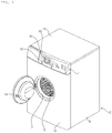
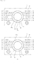
- FIG. 1 is a perspective view of a first embodiment of a laundry treating apparatus.
- a first embodiment of the laundry treating apparatus includes a cabinet 2, and a control panel 4 provided at the cabinet 2.
- the cabinet 2 may be embodied as a case defining an external appearance of the laundry treating apparatus.
- the cabinet 2 may be provided with a laundry port 3 through which laundry is put into or taken out of the cabinet 2.
- the cabinet 2 may be provided therein with a tub (not shown) for containing washing water.
- the tub may be provided therein with a drum 6 which is rotatable therein.
- the cabinet 2 may be provided therein with a motor (not shown) for rotating the drum 6. If the laundry treating apparatus is a dryer, the tub for containing washing water may not be provided in the cabinet 2, and the drum 6 may be rotatably supported by a support installed in the cabinet 2.
- the cabinet 2 may be constructed by bending a single member several times or by coupling a plurality of members to one another.
- the cabinet 2 may include a base pan (not shown), a cabinet body 8 installed on the base pan and having a space for accommodating the tub, a cabinet cover 10 disposed in front of the cabinet body 8 and including the laundry port 3, and a top cover 12 disposed on the cabinet body 8.
- the cabinet body 8 may be constructed by a single member, and may also be constructed by a plurality of members.
- the cabinet body 8 may include a left cover disposed on the left side of the base pan, a right cover disposed on the right side of the base pan, and a rear cover disposed on the rear side of the base pan.
- the cabinet 2 may be constructed by one of various combinations of a plurality of members and may be configured into various modifications.
- the cabinet 2 may be provided with a door 14 for opening or closing the laundry port 30.
- the door 14 may be swingably connected to the cabinet 2 to open or close the laundry port 3, and may also be slidably coupled to the cabinet 2 to open or close the laundry port 3.
- the door 14 may be hinged to the cabinet 2 by means of a hinge element, and thus may be swung about the hinge element to open or close the laundry port 3.
- the control panel 4 may include a manipulation unit.
- the control panel 4 may include a display unit for displaying information of the laundry treating apparatus.
- the control panel 4 may include both the manipulation unit and the display unit.
- the control panel 4 may be disposed on the cabinet cover 10.
- the control panel 4 may be disposed on a front surface of the cabinet 2, and may define a portion of the external appearance of the laundry treating apparatus.
- the control panel 4 may include a control panel body 20 defining an exterior appearance thereof.
- the control panel body 20 may be disposed on the cabinet cover 10.
- the control panel body 20 may provided with the manipulation unit for enabling user manipulation and the display unit for displaying various information of the laundry treating apparatus to a user.
- the control panel 4 may include a rotary knob 50 adapted to be gripped by user fingers to allow user manipulation.
- the rotary knob 50 may be installed to be rotated by a user in order to select one of various treatment courses of the laundry treating apparatus.
- the control panel 4 may further include a window 82 disposed to surround a circumference of the rotary knob 50.
- the laundry treating apparatus may radiate light to the window 82. A user may recognize a course of the laundry treating apparatus by viewing the light radiated to the window 82.
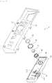
- FIG. 2 is an exploded perspective view illustrating the control panel of the first embodiment of the laundry treating apparatus.
- FIG. 3 is an exploded perspective view illustrating the control panel of the first embodiment of the laundry treating apparatus.
- FIG. 4 is a longitudinal sectional view illustrating a substantial part of the control panel of the first embodiment of the laundry treating apparatus.
- FIG. 5 is a transverse sectional view illustrating a substantial part of the control panel of the first embodiment of the laundry treating apparatus.
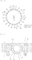
- FIG. 6 is an enlarged front view illustrating a plurality of LEDs of the first embodiment of the laundry treating apparatus.
- the control panel 4 may include a PCB assembly 21 installed in the control panel body 20.
- the PCB assembly 21 may include a PCB 21A, and a PCB mount 21B at which the PCB 21A is installed.
- the PCB mount 21B may be mounted on the control panel body 20 by means of a fastening element such as a screw.
- the control panel 4 may include the manipulation unit which enables a user to manipulate the laundry treating apparatus.
- the PCB assembly 21 may include a rotary switch 46.
- the rotary switch 46 may include a rotating central shaft 47 to which the rotary knob 50 is joined. Upon rotation of the rotating central shaft 47, the rotating central shaft 47 may rotate with the rotary knob 50.
- the rotary switch 46 may include a rotary encoder in which a plurality of switching circuits are provided.
- the rotary switch 46 may detect rotation of the rotating central shaft 47.
- the PCB assembly 21 may further include a tap switch and a touch switch.
- the control panel 4 may include a display component for displaying information of the laundry treating apparatus.
- the PCB assembly 21 may include a light source such as an LED.
- the laundry treating apparatus may include a control panel body 20, the rotary knob 50, a plurality of LEDs 60, and the window 82, all of which may constitute the control panel 4.
- the control panel body 20 may include a rotary knob hole 22 in which the rotary knob 50 is rotatably disposed.
- the rotary knob hole 22 may be formed to be larger than the rotary knob 50.
- the rotary knob hole 22 may be formed into a circular shape.
- control panel body 20 may include one or more indicators 23-29 and 33-39 for displaying treatment courses which may be selected by the rotary knob 50.
- the indicators 23-29 and 33-39 constitute a course display unit that represents various courses (washing programmes) of the laundry treating apparatus as numerals, symbols, characters and the like.
- Each of the indicators 23-29 and 33-39 may be constituted by embossed or engraved lettering formed on the control panel body 20 or a coating applied to the control panel body 20.
- the indicators 23-29 and 33-39 may be provided on the control panel body through various technologies other than printing and coating.
- the indicators 23-29 and 33-39 may include at least two indicators, and the at least two indicators may be disposed around the rotary knob hole 22.
- the indicators 23-29 and 33-39 preferably include a plurality of indicators formed at the control panel body 20. A user may recognize a treatment course of the laundry treating apparatus by observing the plurality of indicators 23-29 and 33-39. Furthermore, a user may select a desired course among the plurality of treatment courses by rotating the rotary knob 50.
- the laundry treating apparatus may radiate light toward an area near one of the plurality of indicators 23-29 and 33-39 selected by a user, and, as such, a user may recognize the indicator closest to the area to which the light is radiated.
- Each of the plurality of indicators 23-29 and 33-39 may include characters representing the corresponding course.
- Each of the plurality of indicators 23-29 and 33-39 may further include a line between the rotary knob hole 22 and the characters.
- the laundry treating apparatus may radiate light to an area near one of lines associated with the plurality of indicators 23-29 and 33-39. At this time, a user may recognize the indicator associated with the line closest to the light radiated from the laundry treating apparatus.
- a user may recognize, among the plurality of indicators 23-29 and 33-39, the indicator corresponding to the area to which light is radiated.
- the indicators 23-29 and 33-39 may include 14 indicators formed at the control panel body 20.
- the laundry treating apparatus may selectively make 14 areas bright so as to represent the treatment courses.
- the indicators 23-29 and 33-39 may include left indicators 23-29 positioned at the left side of the rotary knob hole 22, and right indicators 33-39 positioned at the right side of the rotary knob hole 22.
- the plurality of left indicators 23-29 may be positioned together at the left side of the rotary knob hole 22, and may be spaced apart from one another in the vertical direction.
- the plurality of right indicators 33-39 may be positioned together at the right side of the rotary knob hole 22, and may be spaced apart from one another in the vertical direction.
- the rotary knob 50 which serves as a handle capable of being manipulated by a user, may be connected to the rotary switch 46.
- the rotary knob 50 may be manipulated by a user in a state of being partially disposed in the rotary knob hole 22.
- the rotary knob 50 may have a front portion disposed in front of the rotary knob hole 22 and thus may be exposed to the outside of the laundry treating apparatus.
- the rotary knob 50 may have a rear portion disposed in the rear of the rotary knob hole 22, that is, in the control panel body 20.
- the rotary switch 46 may detect a rotating angle of the rotary knob 50, and the laundry treating apparatus may execute the course selected by rotation of the rotary knob 50.
- the laundry treating apparatus may further include a knob decorative member 56 surrounding an outer circumferential surface of the rotary knob 50.
- the knob decorative member 56 may have an internal diameter larger than an external diameter of the rotary knob 50.
- the knob decorative member 56 may have an external diameter equal to or smaller than a diameter of the rotary knob hole 22.
- the knob decorative member 56 may be coupled to the window 82.
- the plurality of LEDs 60 may be arranged on the PCB 21A in a circular shape.
- the number of the plurality of LEDs 60 may be larger than that of the indicators 23-29 and 33-39.
- the plurality of LEDs 60 may be disposed around the rotary switch 46 of the PCB 21A.
- the plurality of LEDs 60 may be sequentially disposed along an imaginary circle O around the rotary switch 46.
- the plurality of LEDs 60 may be disposed to surround the rotary switch 46.
- the plurality of LEDs 60 may be spaced apart from one another along the imaginary circle O.
- the plurality of LEDs 60 may be positioned spaced apart from one another along the imaginary circle O at substantially regular intervals.
- the plurality of LEDs 60 may be spaced apart from one another along the imaginary circle O in a clockwise or counterclockwise direction.
- the plurality of LEDs 60 may include course LEDs 65-71 and 74-80, and non-course LEDs 61-64, 72 and 73.
- the course LEDs 65-71 and 74-80 may be one or more LEDs that light up while the laundry treating apparatus displays a treatment course.
- the non-course LEDs 61-64, 72 and 73 may be one or more LEDs that do not light up while the laundry treating apparatus displays a treatment course.
- the one or more course LEDs 65-71 and 74-80 may also include a plurality of LEDs.
- the number of the course LEDs 65-71 and 74-80 may be the same as that of the indicators 23-29 and 33-39.
- Each of the course LEDs 65-71 and 74-80 may be assigned one indicator. For example, when 14 indicators are provided, the course LEDs may include 14 course LEDs.
- the course LEDs 65-71 and 74-80 may be turned on or off in accordance with preset control.
- the first LEDs 65-71 and 74-80 may be turned on or off so as to create a first lighting pattern representing power input.
- a plurality of LEDs among the course LEDs 65-71 and 74-80 may be selectively turned on during a period for which the laundry treating apparatus displays a treatment course.
- the number of the non-course LEDs 61-64, 72 and 73 provided at the PCB 21A may be one or more, preferably two or more.
- the number of the non-course LEDs 61-64, 72 and 73 may be less than the number of the indicators 23-29 and 33-39.
- the course LEDs may include 6 course LEDs.
- the non-course LEDs 61-64, 72 and 73 may be turned on or off in accordance with preset control.
- the non-course LEDs 61-64, 72 and 73 may be turned on or off so as to create the lighting pattern representing power input.
- the non-course LEDs 61-64, 72 and 73 may be controlled together with the course LEDs 65-71 and 74-80 while the laundry treating apparatus creates the first lighting pattern representing input of the power supply command.
- the laundry treating apparatus may create the first lighting pattern representing input of the power supply command during a predetermined period of time.
- the course LEDs course LEDs 65-71 and 74-80 and the non-course LEDs 61-64, 72 and 73 may be controlled together to create the first lighting pattern during the predetermined period of time.
- the first lighting pattern may include an arcuate lighting pattern rotating around the rotary knob 50.
- the plurality of LEDs 60 may be controlled such that the arcuate lighting pattern rotates around the rotary knob 50.
- the course LEDs 65-71 and 74-80 and the non-course LEDs 61-64, 72 and 73 of the plurality of LEDs 60 are controlled together to create the arcuate lighting pattern rotating around the rotary knob 50.
- the laundry treating apparatus may not create the first lighting pattern representing input of the power supply command any more but may create a second lighting pattern representing a course from that time. At this time, the laundry treating apparatus may selectively turn on or off only the course LEDs 65-71 and 74-80 while keeping all of the non-course LEDs 61-64, 72 and 73 turned off. From that time, the laundry treating apparatus may create a second lighting pattern representing a course by only the course LEDs 65 ⁇ 71 and 74 ⁇ 80.
- the plurality of LEDs 60 may be arranged such that the non-course LEDs 61-64, 72 and 73 and the course LEDs 65-71 and 74-80 are sequentially disposed along an imaginary circle O.
- the window 82 allows light to pass therethrough.
- the window 82 may be a display window for displaying information of the laundry treating apparatus.
- the window 82 may have an annular shape. Light emitted from the LEDs may be radiated to the window 82, and a user may check information of the laundry treating apparatus by viewing the window 82.
- the window 82 may be at least partially disposed between a circumference of the rotary knob hole 22 and an outer surface of the rotary knob 50.
- the window 82 may be at least partially disposed between the circumference of the rotary knob hole 22 and the outer surface of the rotary knob 50 and thus may be exposed to the outside. Light emitted from the LEDs may be exposed to the outside through the exposed portion of the window 82.
- the exposed portion of the window 82 may have an annular shape.
- the laundry treating apparatus may further include a light guide 90 for protecting the plurality of LEDs 60 and guiding light emitted to the window 82 from the LEDs.
- the light guide 90 may mounted on the PCB 21A by means of a holding element such as a hook.
- the light guide 90 may include an inner wall 92 and an outer wall 94 with an annular space defined therebetween.
- the plurality of LEDs 60 may be circumferentially disposed in the annular space to be spaced apart from one another.
- the light guide 90 may further include at least one rib that divides the annular space into a plurality of cells.
- the rib may be formed to be connected between the inner wall 92 and the outer wall 94.
- the light guide 90 may include a plurality of cells defined by a plurality of ribs. Each of the plurality of LEDs 60 may be disposed in one of the plurality of cells. Light emitted from the LEDs may pass through the cells and may be radiated to the window 82.
- the plurality of LEDs 60 may include first LED groups E and F and second LED groups G and H.
- Each of the first LED groups E and F may include at least one LED for radiating light to each of indicating regions A and B of the window 82 which correspond to the indicators 23-29 and 33-39, respectively.
- Each of second LED groups G and H may include at least one LED for radiating light to each of the other indicating regions C and D of the window 82.
- the other indicating regions C and D of the window 82 may be non-indicating regions C and D of the window 82 which do not correspond to the indicators 23-29 and 33-39.
- the indicating regions A and B and the non-indicating region C and D are now described with reference to FIG. 2 .
- the indicating regions A and B may be partial regions of the window 82, and the non-indicating regions C and D may be the regions of the window 82 other than the indicating regions A and B.
- the indicating regions A and B may be partial regions of the window 82 which face, among regions around the rotary knob hole 22 of the control panel body 20, regions at which the indicators 23-29 and 33-39 are positioned.
- the non-indicating regions C and D may be the other remaining regions of the window 82 which face, among regions around the rotary knob hole 22 of the control panel body 20, regions at which the indicators 23-29 and 33-39 are not positioned.
- a region of the window 82 spanning from a region adjacent to the uppermost indicator 23 of the left indicators 23-29 to a region adjacent to the lowermost indicator 29 of the left indicators 23-29 may be referred to as a left indicating region A.
- a region of the window 82 spanning from a region adjacent to the uppermost indicator 33 of the right indicators 33-39 to a region adjacent to the lowermost indicator 39 of the right indicators 33-39 may be referred to as a right indicating region B.
- the non-indicating regions C and D may include the upper non-indicating region C of the window 82 which is positioned between an upper end of the left indicating region A and an upper end of the right indicating region B.
- the non-indicating regions C and D may include the lower non-indicating region D of the window 82 which is positioned between a lower end of the left indicating region A and a lower end of the right indicating region B.
- the first LED groups E and F and the second LED groups G and H may be alternately arranged on the PCB 21A around the rotating central shaft 47 of the rotary knob 50 in a clockwise or counterclockwise direction.
- the first LED groups E and F and the second LED groups G and H may be arranged along the imaginary circle O at which the plurality of LEDs are positioned such that the first LED group E, the second LED group H, the first LED group F and the second LED group G are positioned in this order in the clockwise direction.
- first LED groups E and F and the second LED groups G and H may be arranged along the imaginary circle O at which the plurality of LEDs are positioned such that the first LED group E, the second LED group G, the first LED group F and the second LED group H are positioned in this order in the counterclockwise direction.
- the first LED groups E and F may include a plurality of LED groups positioned spaced apart from each other at the right and left sides.
- the first LED group E and F may include the first left LED group E for emitting light to a left region of the window 82 positioned at the left side of the rotary knob 50, and the first right LED group F for emitting light to a right region of the window 82 positioned at the right side of the rotary knob 50.
- the first left LED group E may include at least one LED capable of emitting light to the left indicating region A of the window 82.
- the first right LED group F may include at least one LED capable of emitting light to the right indicating region B of the window 82.
- the second LED groups G and H may include a plurality of LED groups positioned vertically spaced apart from each other.
- the second LED group G and H may include the second upper LED group G for emitting light to an upper region of the window 82 positioned above the rotary knob 50, and the second lower LED group H for emitting light to a lower region of the window 82 positioned below the rotary knob 50.
- the second upper LED group G may include at least one LED capable of emitting light to the upper non-indicating region C of the window 82.
- the second lower LED group H may include at least one LED capable of emitting light to the lower non-indicating region D of the window 82.
- the plurality of LEDs 60 may be arranged along the imaginary circle O such that the first left LED group E, the second lower LED group H, the first right LED group F and the second upper LED group G are positioned in this order in the clockwise direction. Conversely, the plurality of LEDs 60 may be arranged along the imaginary circle O such that the first left LED group E, the second upper LED group G, the first right LED group F and the second lower LED group H are positioned in this order in the counterclockwise direction.
- the first LED groups E and F may include the course LEDs 65-71 and 74-80, and the second LED groups G and H may include the non-course LEDs 61-64, 72 and 73.
- the first LED groups E and F may create the first lighting pattern together with the second LED groups G and H.
- the first lighting pattern may include a lighting pattern configured such that an arcuate lighting pattern PT2 is first created and the arcuate lighting pattern PT2 rotates around the rotary knob 50.
- the first lighting pattern may further include a lighting pattern configured such that the arcuate lighting pattern PT2 rotating around the rotary knob 50 is gradually reduced in size at a specific position.
- the first lighting pattern may further include a lighting pattern configured such that the reduced lighting pattern maintains a predetermined size at a specific position.
- the first lighting pattern may be a variable lighting pattern configured such that a lighting pattern gradually varying in size and position maintains a lighting pattern having the reduced size at a specific position.
- the first lighting pattern may be a variable lighting pattern that utilizes both the indicating regions A and B and the non-indicating regions C and D of the window 82.
- first LED groups E and F only the LEDs corresponding to a predetermined course after creation of the first lighting pattern may be maintained in an on state.
- a plurality of LEDs of the first LED groups E and F may be selectively turned on.
- the second LED groups G and H may be maintained in an off state after creation of the first lighting pattern.
- the second LED groups G and H may be maintained in an off state.
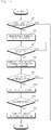
- FIG. 7 is a flowchart illustrating a first embodiment of a method of controlling the laundry treating apparatus.
- the method of controlling the laundry treating apparatus of this embodiment may include initial operations S1, S2, S3, S4, S5 and S6 of creating a first lighting pattern and course display operations S7 and S8 of creating a second lighting pattern.
- the initial operations S1, S2, S3, S4, S5 and S6 may create the first lighting pattern configured such that a plurality of LEDs 60 which have a larger number than that of the plurality of indicators 23-29 and 33-39 formed at the control panel body 20 and are arranged in a circular shape represent the power input.
- the first lighting pattern may include a lighting pattern configured such that the arcuate lighting pattern PT2 rotates around the rotary knob 50.
- the initial operations S1, S2, S3, S4, S5 and S6 may be initiated.
- a user may input a power supply command through a power key provided at the control panel 4.
- the laundry treating apparatus may be controlled to perform the initial operations S1, S2, S3, S4, S5 and S6.
- the method of controlling the laundry treating apparatus may include a first procedure S1 and S2 in which some LEDs 63-71 of the plurality of LEDs are sequentially turned on in the clockwise or counterclockwise direction to create the arcuate lighting pattern PT2 around the rotary knob 50.
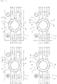
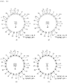
- FIG. 8 is a view illustrating the plurality of LEDs when the first embodiment of the laundry treating apparatus performs the first procedure of the first lighting pattern.
- FIG. 9 is a view illustrating the control panel when the first embodiment of the laundry treating apparatus according to the present invention performs the first procedure of the first lighting pattern.
- the plurality of LEDs 60 may be controlled to create the arcuate lighting pattern PT2 with time.
- FIG. 8(I) illustrates a case in which a predetermined reference LED 63 of the plurality of LEDs 60 is turned on first.
- FIG. 9(K) illustrates the control panel 4 when the one predetermined reference LED 63 is turned on as illustrated in FIG. 8(I) .
- the reference LED 63 may be a first predetermined LED configured to be turned on first in the first lighting pattern.
- the area of the window 82 that corresponds to the reference LED 63 may be brightly irradiated.
- a small lighting pattern PT1 having a shape similar to a rectangular or circular shape may be created as illustrated in FIG. 9(K) .
- FIG. 8(J) illustrates a case in which a predetermined number of LEDs 63-70 of the plurality of LEDs 60 are sequentially turned on.
- FIG. 9(L) illustrates the control panel 4 when the predetermined number of LEDs 63 are sequentially turned on as illustrated in FIG. 8(J) .
- the plurality of LEDs 60 may be turned on in such a manner that the reference LED 63 is turned on first and then the LEDs are turned on in the clockwise or counterclockwise direction with the result that the arcuate lighting pattern PT2 may be created around the rotary knob 50.
- the arcuate lighting pattern PT2 created on the window 82 may be increased in size as the number of lit LEDs is increased.
- the plurality of LEDs 60 may be turned on in such a manner that the reference LED 63 is turned on and then the LEDs are turned on in the counterclockwise direction from the reference LED 63.
- LEDs adjacent to the most recently lit LED may be turned on until the number of lit LEDs of the plurality of LEDs reaches the predetermined number. When the number of lit LEDs reaches the predetermined number, the number of lit LEDs may not be increased any more.
- the area of the window 82 that corresponds to the predetermined number of lit LEDs 63-70 is brightly irradiated with the result that a larger arcuate lighting pattern PT2 may be created on the window 82 as illustrated in FIG. 9(L) .
- the initial operations S1, S2, S3, S4, S5 and S6 may further include a second procedure S3 and S4 in which the arcuate lighting pattern PT2 rotates around the rotary knob 50.
- the second procedure S3 and S4 may be initiated when the number of LEDs lit in the first procedure S1 and S2 reaches the predetermined number.
- the plurality of LEDs may be sequentially turned on and then turned off.
- the arcuate lighting pattern PT2 may have a leading end PL at which the plurality of LEDs are sequentially turned on in the clockwise or counterclockwise direction and a posterior end PM at which the plurality of LEDs are sequentially turned off in the clockwise or counterclockwise direction.
- the arcuate lighting pattern PT2 may gradually move around the rotary knob 50 while maintaining its own size.
- FIG. 10 is a view illustrating the plurality of LEDs when the first embodiment of the laundry treating apparatus performs the second procedure of the first lighting pattern.
- FIG. 11 is a view illustrating the control panel when the first embodiment of the laundry treating apparatus according to the present invention performs the second procedure of the first lighting pattern.
- the plurality of LEDs 60 may be controlled in such a manner that the arcuate lighting pattern PT2 created in the first procedure rotates around the rotary knob 50.
- the arcuate lighting pattern PT2 created in the first procedure may gradually move with time while maintaining its own size.
- FIG. 10(M) illustrates a case in which the LED 63 that was turned on first among the LEDs turned on in the first procedure of the first lighting pattern is turned off and the LED 71 adjacent to the LED 70 turned off last is turned on.
- FIG. 11 (Q) is a view illustrating the control panel 4 when the plurality of LEDs 60 are turned on as illustrated in FIG. 10(M) , in which the lighting pattern PT2 having the same size as that of the arcuate lighting pattern shown in FIG. 9(L) and moved around the rotary knob 50 by a predetermined angle may be created on the window 82.
- the plurality of LEDs 60 may be sequentially turned on in the clockwise or counterclockwise while being sequentially turned off in the clockwise or counterclockwise direction with time.
- FIG. 10 (N) illustrates a case in which the LED 72 adjacent to the LED 71 that was turned off last is turned on among the currently lit LEDs and the LED 64 that was turned on first among the currently lit LEDs is turned off.
- FIG. 11 (R) is a view illustrating the control panel 4 when the plurality of LEDs 60 are turned on as illustrated in FIG. 10(N) , in which the lighting pattern PT2 having the same size as that of the arcuate lighting pattern shown in FIG. 11(Q) and moved around the rotary knob 50 by a predetermined angle may be created on the window 82.
- the plurality of LEDs 60 may be controlled in such a manner that, when the LED nearest the LED that was turned on last among the currently lit LEDs is turned on, the LED that was turned on first among the currently lit LEDs is turned off.
- the plurality of LEDs 60 may create a variable lighting pattern which rotates around the rotary knob 50 while maintaining the size of the arcuate lighting pattern PT2.
- the plurality of LEDs 60 are repeatedly turned on and turned off with time in the above-described manner.
- FIG. 10(O) illustrates a case in which a procedure configured such that the LED nearest the LED that was turned on last among the currently lit LEDs is turned on and the LED that was turned on first among the currently lit LEDs is turned off is performed several times.
- FIG. 11 (S) is view illustrating the control panel 4 in which the plurality of LEDs 60 are turned on as illustrated in FIG. 10(O) , in which the lighting pattern PT2 having the same size as that of the arcuate lighting pattern shown in FIG. 11 (R) and moved around the rotary knob 50 may be created on the window 82.
- the predetermined LED 71 may be a second predetermined LED which is previously determined.
- the predetermined number of times is preferably twice or more. This is because the arcuate lighting pattern PT2 may not rotate one turn or more around the rotary knob 50 if the predetermined number of times is once.
- FIG. 10(P) illustrates a case in which the predetermined LED 71 of the plurality of LEDs 60 is turned on the predetermined number of times.
- FIG. 11 (T) is a view illustrating the control panel 4 when the plurality of LEDs 60 are turned on as illustrated in FIG. 10 (P) , in which the lighting pattern PT2 having the same size as that of the arcuate lighting pattern shown in FIG. 11 (S) and moved to the position corresponding to the predetermined LED 71 may be created on the window 82.
- the initial operations S1, S2, S3, S4, S5 and S6 may further include a third procedure S5 and S6 in which, when the predetermined LED 71 of the plurality of LEDs 60 is turned on the predetermined number of times (for example, twice), the LEDs other than the predetermined LED 71 among the currently lit LEDs are sequentially turned off.
- the third procedure S5 and S6 may be initiated.
- the third procedure S5 and S6 may be under the condition that only the predetermined LED 71 is turned on.
- the state that the predetermined LED 71 is turned on may be maintained.
- FIG. 12 is a view illustrating the plurality of LEDs when the first embodiment of the laundry treating apparatus performs the third procedure of the first lighting pattern.
- FIG. 13 is a view illustrating the control panel when the first embodiment of the laundry treating apparatus according to the present invention performs the third procedure of the first lighting pattern.
- the plurality of LEDs 60 may be controlled in such a manner that the arcuate lighting pattern PT2 rotating around the rotary knob 50 is gradually decreased in size at a specific position and the reduced lighting pattern maintains a predetermined size and is held at a specific position.
- FIG. 12(U) illustrates a case in which, when the predetermined LED 71 of the plurality of LEDs 60 is turned on the predetermined number of times, the LED 64 that was turned on first among the lit LEDs is turned off.
- FIG. 13 (W) is a view illustrating the control panel 4 when the plurality of LEDs are turned on as illustrated in FIG. 12 (U) , in which the lighting pattern PT2 smaller than that of the arcuate lighting pattern shown in FIG. 11(T) may be created on the window 82.
- the plurality of LEDs 60 may be controlled in such a manner that the LEDs other than the predetermined LED 71 among the currently lit LEDs are sequentially turned off and the LEDs other than the predetermined LED 71 are sequentially turned off in the order that the LEDs were turned on.
- FIG. 12(V) illustrates a case in which only the predetermined LED 71 of the plurality of LEDs 60 is turned on whereas all of the other LEDs are turned off.
- FIG. 13(X) is a view illustrating the control panel 4 when only the predetermined LED 71 is turned on, in which the lighting pattern PT3 smaller than that of the arcuate lighting pattern shown in FIG. 13(W) may be created on the window 82.
- the plurality of LEDs 60 may be turned on and turned off in the order shown in FIGS. 8 , 10 and 12 , and the plurality of LEDs 60 may create the lighting pattern that moves in the order shown in FIGS. 9 , 11 and 13 . Thereafter, only the predetermined LED 71 may be maintained in an on state until a user rotates the rotary knob 50.
- the initial operations S1, S2, S3, S4, S5 and S6 may be completed when the rotary knob 50 is rotated under the condition that the predetermined LED 71 is turned on.
- the method of controlling the laundry treating apparatus may initiate course display operations S7 and S8.
- some LEDs 65-71 and 74-80 of the plurality of LEDs 60 which radiate light toward the indicating regions A and B may be selectively turned on to create the second lighting pattern and the remaining LEDs 61-64, 72 and 73 for radiating light toward the regions C and D other than the indicating regions may be turned off.
- the rotary knob 50 When the rotary knob 50 is rotated under the condition that the predetermined LED 71 is turned on, the some LEDs 65-71 and 74-80 of the plurality of LEDs 60 which radiate light toward the indicating regions A and B may be turned on and turned off by rotation of the rotary knob 50.
- FIG. 14 is a view illustrating the plurality of LEDs when the first embodiment of the laundry treating apparatus creates the second lighting pattern.
- FIG. 15 is a view illustrating the control panel when the first embodiment of the laundry treating apparatus according to the present invention creates the second lighting pattern.
- a user may select a specific course by rotating the rotary knob 50 by a predetermined angle under the condition that only the predetermined LED 71 is turned on.
- FIG. 15 is a view illustrating the control panel 4 when the predetermined LED 71 is turned off whereas the LED 69 corresponding to the course selected by a user is turned on.
- a lighting pattern PT4 having the same size as the lighting pattern PT3 and having a position different from the lighting pattern PT3 under the condition that only the predetermined LED 71 is turned on may be created on the window 82.
- the laundry treating apparatus may be operated in the course selected by a user (S10 and S11).
- a user may input an operation command through an operation key provided at the control panel 4 during the course display operations S7 and S8, and the laundry treating apparatus may be operated in the selected course for a period of time determined in accordance with the selected course.
- the method may complete the operation in the course (Sll).
- the method may turn off the LED 69 turned on at the time that a course is selected by rotation of the rotary knob 50 (S12).
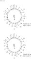
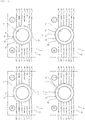
- FIG. 16 is a view illustrating the plurality of LEDs when a power supply command is input to a second embodiment of the laundry treating apparatus according to the present invention.
- FIG. 17 is a view illustrating lighting patterns created on the control panel when the power supply command is input to the second embodiment of the laundry treating apparatus.
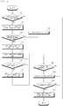
- FIG. 18 is a flowchart illustrating a second embodiment of the method of controlling the laundry treating apparatus.
- the plurality of LEDs 60 when a power supply command is input to the laundry treating apparatus, the plurality of LEDs 60 may be sequentially turned on in the clockwise or counterclockwise direction.
- the reference LED 63 may be turned on first, and then the remaining LEDs 64-80, 61 and 62 that are currently turned off may be turned on.
- all of the LEDs 64-80, 61 and 62 turned on after turning on of the reference LED 63 may be sequentially turned on in the clockwise or counterclockwise direction.
- this embodiment may be identical or similar to the first embodiment in construction and function with the exception that all of the LEDs 60 are turned on, and thus a detailed description thereof is omitted.
- FIG. 16 (I') illustrates a case in which the reference LED 63 is turned on after input of a power supply command.
- FIG. 17 (0') illustrates a case in which a small lighting pattern PT1 having a shape similar to a rectangular or circular shape at the time that the reference LED 63 is turned on is created on the window 82.
- FIG. 16 (J') illustrates a case in which the LED 64 nearest the lighting reference LED 63 in a clockwise or counterclockwise direction is turned on after turning on of the reference LED 63.
- FIG. 17 (P') illustrates a case in which a lighting pattern PT2 larger than the lighting pattern PT1 shown in FIG. 17 (0') is created on the window 82 at the time that the LED 64 nearest the reference LED 63 is turned on.
- FIG. 16 (L') illustrates a case in which the sequential turning on of the plurality of LEDs is further performed several times.
- FIG. 17 (R') illustrates a case in which a lighting pattern PT2 larger than the lighting pattern shown in FIG. 17 (P') is created on the window 82.
- FIG. 16 (M') illustrates a case in which all of the plurality of LEDs 60 are sequentially turned on.
- FIG. 17 (S') illustrates a case in which an annular lighting pattern PT5 is created on the window 82.
- the lighting pattern created on the window 82 may be gradually increased in size and may have a shape that is changed in the order of a circular shape, an arcuate shape and an annular shape, as illustrated in FIG. 17 .
- a course selection command may be input after all of the plurality of LEDs 60 are turned on. All of the plurality of LEDs 60 may be maintained in an on state until rotation of the rotary knob 50 is detected.
- the method according to this embodiment may include initial operations S1 and S2' and course display operations S7 and S8'.
- the plurality of LEDs 60 may be sequentially turned on in the clockwise or counterclockwise direction in the initial operations S1 and S2'.
- the lighting pattern which is gradually increased in size and has a shape changing in the order of a circular shape, an arcuate shape and an annular shape may be created on the window 82.
- the course display operations S7 and S8' may be configured such that, by input of a course selection command, some LEDs 65-71 and 74-80 of the plurality of LEDs 60 which radiate light to the indicating regions A and B are selectively turned on to create the second lighting pattern whereas the remaining LEDs 61-64, 72 and 73 radiating light to the regions C and D excluding the indicating regions are turned off.
- the course display operations S7 and S8' may be initiated when the rotary knob 50 is manipulated under the condition that all of the plurality of LEDs 60 are turned on.
- the LED of the plurality of LEDs 60 which corresponds to a course selected by a user, may be turned on and all of the other LEDs may be turned off.
- FIG. 19 is a view illustrating the plurality of LEDs when a power supply command is input to a third embodiment of the laundry treating apparatus according to the present invention.
- FIG. 20 is a view illustrating a lighting pattern created on the window when a power supply command is input to a third embodiment of the laundry treating apparatus.
- FIG. 21 is a flowchart illustrating a third embodiment of the method of controlling the laundry treating apparatus according to the present invention.
- the plurality of LEDs 60 when a power supply command is input to the laundry treating apparatus, the plurality of LEDs 60 may be sequentially turned on in the clockwise or counterclockwise direction.
- the plurality of LEDs 60 may be maintained in an on state for a predetermined period of time after all of the plurality of LEDs 60 are turned on. After lapse of the predetermined period of time, all of the plurality of LEDs 60 may be turned off. After all of the plurality of LEDs 60 are turned off, only the predetermined LED 71 may be turned on.
- the laundry treating apparatus may be identical or similar to the first embodiment of the laundry treating apparatus according to the present invention in construction and function, aside from the manner of turning on and off the plurality of LEDs 60, a detailed description thereof is omitted.
- FIG. 19 (M") illustrates a case in which all of the plurality of LEDs 60 are sequentially turned on in the clockwise or counterclockwise direction from the reference LED 63 after a power supply command is input.
- FIG. 20 (P") illustrates a case in which an annular lighting pattern PT5 is created on the window 82 by turning on the plurality of LEDs 60 as shown in FIG. 19 (M"). After all of the plurality of LEDs 60 are turned on, the plurality of LEDs 60 may be maintained in an on state for a predetermined period of time (for example, 0.5 seconds).
- a predetermined period of time for example, 0.5 seconds
- FIG. 19 (N") illustrates a case in which all of the plurality of LEDs 60 are turned off after lapse of the predetermined period of time (for example, 0.5 seconds).
- FIG. 20 (Q") illustrates a case in which a lighting pattern is not created on the window 82 by turning off the plurality of LEDs 60 as shown in FIG. 19 (N").
- FIG. 19 (0") illustrates a case in which only the predetermined LED 71 is turned on after the plurality of LEDs 60 are turned off.
- FIG. 20 (R") illustrates a case in which a small lighting pattern PT3 having a shape similar to a rectangular or circular shape is created in an area of the window 82 corresponding to the predetermined LED 71.
- This embodiment of the method of controlling the laundry treating apparatus may include initial operations S1, S2", S3", S4", S5" and S6” and course display operations S7 and S8.
- the initial operations S1, S2", S3", S4", S5" and S6” may include a first procedure S1 and S2" in which the plurality of LEDs 60 are sequentially turned on in the clockwise or counterclockwise direction.
- the plurality of LEDs 60 may be sequentially turned on starting from the reference LED 63, and all of the plurality of LEDs 60 may be turned on as illustrated in FIG. 19 (M"). At this time, an annular lighting pattern PT5 may be created on the window 82.
- the initial operations S1, S2", S3", S4", S5" and S6" may include a second procedure S3" and S4" in which, after all of the plurality of LEDs 60 are turned on, the plurality of LEDs are maintained in an on state for a predetermined period of time.
- the second procedure S3" and S4 after the LED 62 among the plurality of LEDs 60 is turned on last in the first procedure S1 and S2", all of the plurality of LEDs 60 may be maintained in an on state for the predetermined period of time.
- the initial operations S1, S2", S3", S4", S5" and S6" may further include a third procedure S5" in which all of the plurality of LEDs are turned off after lapse of the predetermined period of time.
- all of the plurality of LEDs 60 may be turned off as illustrated in FIG. 19 (M"). At this time, a lighting pattern may not be created on the window 82.
- the initial operations S1, S2", S3", S4", S5" and S6" may further include a fourth procedure S6" in which the predetermined LED 71 is turned on.
- the fourth procedure S6 only the predetermined LED 71 of the plurality of LEDs 60 is turned on as illustrated in FIG. 19 (0").
- a small lighting pattern PT3 having a shape similar to a rectangular or circular shape may be created on the area of the window 8 corresponding to the predetermined LED 71.
- this embodiment of the method of controlling the laundry treating apparatus may be identical or similar to the first embodiment of the method in operations S7, S8, S9, S10, S11 and S12 other than the initial operations S1, S2", S3", S4", S5" and S6" and in function thereof, the corresponding components are denoted by the same numerals and a detailed description thereof is omitted.
- the present disclosure may create a lighting pattern at an indicating region of a window which represents a course of a laundry treating apparatus, and may create an arcuate or annular lighting pattern at indicating regions and non-indicating regions of the window which represents information other than a course display.
- a continuous lighting pattern may be created around a rotary knob.
- a user may conveniently recognize whether or not a power supply command is input to the laundry treating apparatus, where the rotary knob is positioned, and the like.
- a reference position in rotation of the rotary knob may be displayed and user convenience is improved.
Landscapes
- Engineering & Computer Science (AREA)
- Textile Engineering (AREA)
- General Engineering & Computer Science (AREA)
- Physics & Mathematics (AREA)
- General Physics & Mathematics (AREA)
- Automation & Control Theory (AREA)
- Control Of Washing Machine And Dryer (AREA)
- Detail Structures Of Washing Machines And Dryers (AREA)
- Main Body Construction Of Washing Machines And Laundry Dryers (AREA)
- Illuminated Signs And Luminous Advertising (AREA)
- Accessory Of Washing/Drying Machine, Commercial Washing/Drying Machine, Other Washing/Drying Machine (AREA)
- Massaging Devices (AREA)
- Microelectronics & Electronic Packaging (AREA)
Applications Claiming Priority (1)
| Application Number | Priority Date | Filing Date | Title |
|---|---|---|---|
| KR1020140046235A KR102214660B1 (ko) | 2014-04-17 | 2014-04-17 | 의류처리기기 및 그 제어방법 |
Publications (2)
| Publication Number | Publication Date |
|---|---|
| EP2933368A1 EP2933368A1 (en) | 2015-10-21 |
| EP2933368B1 true EP2933368B1 (en) | 2018-03-14 |
Family
ID=52991541
Family Applications (1)
| Application Number | Title | Priority Date | Filing Date |
|---|---|---|---|
| EP15164123.0A Active EP2933368B1 (en) | 2014-04-17 | 2015-04-17 | Laundry treating apparatus and method of controlling the same |
Country Status (8)
| Country | Link |
|---|---|
| US (1) | US20150299930A1 (ko) |
| EP (1) | EP2933368B1 (ko) |
| JP (1) | JP6671857B2 (ko) |
| KR (1) | KR102214660B1 (ko) |
| CN (1) | CN105040362B (ko) |
| AU (1) | AU2015201934B2 (ko) |
| BR (1) | BR102015008483B1 (ko) |
| RU (1) | RU2622817C2 (ko) |
Families Citing this family (12)
| Publication number | Priority date | Publication date | Assignee | Title |
|---|---|---|---|---|
| KR102133189B1 (ko) * | 2014-04-21 | 2020-07-13 | 엘지전자 주식회사 | 의류처리기기 |
| KR102243658B1 (ko) * | 2014-11-26 | 2021-04-23 | 엘지전자 주식회사 | 세탁장치 |
| EP3168355B1 (en) | 2015-11-16 | 2019-10-23 | Electrolux Appliances Aktiebolag | Household appliance with a user interface element |
| EP3168357B1 (en) * | 2015-11-16 | 2020-01-22 | Electrolux Appliances Aktiebolag | Laundry treatment appliance |
| EP3168356B2 (en) * | 2015-11-16 | 2023-08-16 | Electrolux Appliances Aktiebolag | Household appliance with a rotational user interface element |
| WO2018024578A1 (en) * | 2016-08-05 | 2018-02-08 | Arcelik Anonim Sirketi | A laundry washer-dryer enabling ease of use |
| US10330324B2 (en) * | 2017-03-07 | 2019-06-25 | Haier Us Appliance Solutions, Inc. | Appliance and illuminated knob assembly |
| CN108570821B (zh) * | 2017-03-07 | 2021-10-22 | 青岛胶南海尔洗衣机有限公司 | 一种用于家用电器的显示控制装置及洗衣机 |
| CN106968085B (zh) * | 2017-04-28 | 2021-09-14 | 青岛海尔洗涤电器有限公司 | 一种洗衣机的旋钮组件、装配方法以及洗衣机 |
| WO2019189586A1 (ja) * | 2018-03-29 | 2019-10-03 | 富士フイルム株式会社 | 光学素子 |
| US11113933B1 (en) * | 2020-02-28 | 2021-09-07 | Therm-Omega-Tech, Inc. | Visual indication system for feedback controller |
| CN113721700B (zh) * | 2021-08-26 | 2022-12-16 | 广东美的厨房电器制造有限公司 | 旋钮端盖及其安装方法、旋钮组件、烹饪器具和工装 |
Family Cites Families (15)
| Publication number | Priority date | Publication date | Assignee | Title |
|---|---|---|---|---|
| US6341202B1 (en) * | 1999-06-22 | 2002-01-22 | Asahi Kogaku Kogyo Kabushiki Kaisha | Operation dial with an illuminator for a camera |
| JP3462799B2 (ja) * | 1999-06-22 | 2003-11-05 | ペンタックス株式会社 | カメラの照明付き操作部材 |
| CN1318680A (zh) * | 2000-04-19 | 2001-10-24 | 黑龙江省农垦建筑总公司 | 冷却塔人字形柱更换施工方法 |
| JP2002095886A (ja) * | 2000-09-26 | 2002-04-02 | Toshiba Corp | 洗濯機 |
| CN1158441C (zh) * | 2001-05-25 | 2004-07-21 | 陈猛 | 一种金属板幕墙安装结构 |
| JP3937765B2 (ja) * | 2001-07-25 | 2007-06-27 | ティアック株式会社 | インジケータ付きスイッチ装置 |
| US7000436B2 (en) * | 2001-08-06 | 2006-02-21 | Emerson Electric Co. | Appliance control system with hyperspin mode |
| US6813911B2 (en) * | 2001-08-06 | 2004-11-09 | Emerson Electric Company | Appliance control system with cycle selection detection |
| DE10144666B4 (de) * | 2001-09-11 | 2004-02-05 | BSH Bosch und Siemens Hausgeräte GmbH | Ansteuerung eines Leuchtrings |
| DE10144668A1 (de) * | 2001-09-11 | 2003-03-27 | Bsh Bosch Siemens Hausgeraete | Anzeige an einem Haushaltgerät |
| KR101203550B1 (ko) | 2005-05-23 | 2012-11-21 | 엘지전자 주식회사 | 컨트롤 패널 어셈블리 |
| US7554463B2 (en) * | 2006-04-18 | 2009-06-30 | Whirlpool Corporation | Appliance information communication system |
| KR101309298B1 (ko) * | 2007-05-25 | 2013-09-17 | 삼성전자주식회사 | 세탁기 및 그 컨트롤 패널 어셈블리 |
| KR101704418B1 (ko) * | 2012-04-12 | 2017-02-22 | 삼성전자주식회사 | 컨트롤 패널 어셈블리 및 이를 포함하는 세탁기 |
| WO2015054225A1 (en) * | 2013-10-07 | 2015-04-16 | Google Inc. | Smart-home hazard detector providing non-alarm status signals at opportune moments |
-
2014
- 2014-04-17 KR KR1020140046235A patent/KR102214660B1/ko active IP Right Grant
-
2015
- 2015-04-15 BR BR102015008483-8A patent/BR102015008483B1/pt active IP Right Grant
- 2015-04-16 AU AU2015201934A patent/AU2015201934B2/en active Active
- 2015-04-16 RU RU2015114268A patent/RU2622817C2/ru not_active IP Right Cessation
- 2015-04-17 US US14/689,305 patent/US20150299930A1/en not_active Abandoned
- 2015-04-17 JP JP2015085126A patent/JP6671857B2/ja active Active
- 2015-04-17 CN CN201510184227.0A patent/CN105040362B/zh active Active
- 2015-04-17 EP EP15164123.0A patent/EP2933368B1/en active Active
Non-Patent Citations (1)
| Title |
|---|
| None * |
Also Published As
| Publication number | Publication date |
|---|---|
| BR102015008483A2 (pt) | 2015-10-27 |
| US20150299930A1 (en) | 2015-10-22 |
| KR20150120232A (ko) | 2015-10-27 |
| AU2015201934A1 (en) | 2015-11-05 |
| JP2015205182A (ja) | 2015-11-19 |
| RU2622817C2 (ru) | 2017-06-20 |
| JP6671857B2 (ja) | 2020-03-25 |
| BR102015008483A8 (pt) | 2016-03-08 |
| RU2015114268A (ru) | 2016-11-10 |
| CN105040362B (zh) | 2017-10-27 |
| CN105040362A (zh) | 2015-11-11 |
| KR102214660B1 (ko) | 2021-02-09 |
| EP2933368A1 (en) | 2015-10-21 |
| AU2015201934B2 (en) | 2016-11-24 |
| BR102015008483B1 (pt) | 2022-04-05 |
Similar Documents
| Publication | Publication Date | Title |
|---|---|---|
| EP2933368B1 (en) | Laundry treating apparatus and method of controlling the same | |
| US9725843B2 (en) | Laundry treating apparatus | |
| EP2933369B1 (en) | Laundry treating apparatus | |
| KR101481550B1 (ko) | 세탁장치의 입력장치 및 그 제어방법 | |
| KR100531333B1 (ko) | 세탁기 | |
| US9976244B2 (en) | Laundry treatment apparatus | |
| KR20090131826A (ko) | 세탁장치의 입력장치 | |
| KR102248073B1 (ko) | 세탁장치 | |
| EP3170933A1 (en) | Clothes handling apparatus and method for controlling same | |
| US20170260675A1 (en) | Washer | |
| KR100837921B1 (ko) | 라이트링의 제어장치 | |
| EP4365354A1 (en) | Laundry treating apparatus | |
| EP4365356A1 (en) | Laundry treating apparatus | |
| KR20100104819A (ko) | 세탁장치 | |
| KR102423500B1 (ko) | 의류처리장치 | |
| KR20230003872A (ko) | 의류처리장치 | |
| KR20230001309A (ko) | 의류처리장치 | |
| KR20230064595A (ko) | 세탁장치 | |
| KR20210047846A (ko) | 세탁장치 |
Legal Events
| Date | Code | Title | Description |
|---|---|---|---|
| PUAI | Public reference made under article 153(3) epc to a published international application that has entered the european phase |
Free format text: ORIGINAL CODE: 0009012 |
|
| 17P | Request for examination filed |
Effective date: 20150417 |
|
| AK | Designated contracting states |
Kind code of ref document: A1 Designated state(s): AL AT BE BG CH CY CZ DE DK EE ES FI FR GB GR HR HU IE IS IT LI LT LU LV MC MK MT NL NO PL PT RO RS SE SI SK SM TR |
|
| AX | Request for extension of the european patent |
Extension state: BA ME |
|
| RBV | Designated contracting states (corrected) |
Designated state(s): AL AT BE BG CH CY CZ DE DK EE ES FI FR GB GR HR HU IE IS IT LI LT LU LV MC MK MT NL NO PL PT RO RS SE SI SK SM TR |
|
| 17Q | First examination report despatched |
Effective date: 20161122 |
|
| GRAP | Despatch of communication of intention to grant a patent |
Free format text: ORIGINAL CODE: EPIDOSNIGR1 |
|
| INTG | Intention to grant announced |
Effective date: 20170912 |
|
| GRAJ | Information related to disapproval of communication of intention to grant by the applicant or resumption of examination proceedings by the epo deleted |
Free format text: ORIGINAL CODE: EPIDOSDIGR1 |
|
| GRAR | Information related to intention to grant a patent recorded |
Free format text: ORIGINAL CODE: EPIDOSNIGR71 |
|
| GRAS | Grant fee paid |
Free format text: ORIGINAL CODE: EPIDOSNIGR3 |
|
| GRAA | (expected) grant |
Free format text: ORIGINAL CODE: 0009210 |
|
| INTC | Intention to grant announced (deleted) | ||
| AK | Designated contracting states |
Kind code of ref document: B1 Designated state(s): AL AT BE BG CH CY CZ DE DK EE ES FI FR GB GR HR HU IE IS IT LI LT LU LV MC MK MT NL NO PL PT RO RS SE SI SK SM TR |
|
| INTG | Intention to grant announced |
Effective date: 20180205 |
|
| REG | Reference to a national code |
Ref country code: GB Ref legal event code: FG4D |
|
| REG | Reference to a national code |
Ref country code: CH Ref legal event code: EP Ref country code: AT Ref legal event code: REF Ref document number: 978985 Country of ref document: AT Kind code of ref document: T Effective date: 20180315 |
|
| REG | Reference to a national code |
Ref country code: IE Ref legal event code: FG4D |
|
| REG | Reference to a national code |
Ref country code: DE Ref legal event code: R096 Ref document number: 602015008645 Country of ref document: DE |
|
| REG | Reference to a national code |
Ref country code: FR Ref legal event code: PLFP Year of fee payment: 4 |
|
| REG | Reference to a national code |
Ref country code: NL Ref legal event code: MP Effective date: 20180314 |
|
| REG | Reference to a national code |
Ref country code: LT Ref legal event code: MG4D |
|
| PG25 | Lapsed in a contracting state [announced via postgrant information from national office to epo] |
Ref country code: CY Free format text: LAPSE BECAUSE OF FAILURE TO SUBMIT A TRANSLATION OF THE DESCRIPTION OR TO PAY THE FEE WITHIN THE PRESCRIBED TIME-LIMIT Effective date: 20180314 Ref country code: LT Free format text: LAPSE BECAUSE OF FAILURE TO SUBMIT A TRANSLATION OF THE DESCRIPTION OR TO PAY THE FEE WITHIN THE PRESCRIBED TIME-LIMIT Effective date: 20180314 Ref country code: HR Free format text: LAPSE BECAUSE OF FAILURE TO SUBMIT A TRANSLATION OF THE DESCRIPTION OR TO PAY THE FEE WITHIN THE PRESCRIBED TIME-LIMIT Effective date: 20180314 Ref country code: NO Free format text: LAPSE BECAUSE OF FAILURE TO SUBMIT A TRANSLATION OF THE DESCRIPTION OR TO PAY THE FEE WITHIN THE PRESCRIBED TIME-LIMIT Effective date: 20180614 Ref country code: FI Free format text: LAPSE BECAUSE OF FAILURE TO SUBMIT A TRANSLATION OF THE DESCRIPTION OR TO PAY THE FEE WITHIN THE PRESCRIBED TIME-LIMIT Effective date: 20180314 |
|
| REG | Reference to a national code |
Ref country code: AT Ref legal event code: MK05 Ref document number: 978985 Country of ref document: AT Kind code of ref document: T Effective date: 20180314 |
|
| PG25 | Lapsed in a contracting state [announced via postgrant information from national office to epo] |
Ref country code: LV Free format text: LAPSE BECAUSE OF FAILURE TO SUBMIT A TRANSLATION OF THE DESCRIPTION OR TO PAY THE FEE WITHIN THE PRESCRIBED TIME-LIMIT Effective date: 20180314 Ref country code: SE Free format text: LAPSE BECAUSE OF FAILURE TO SUBMIT A TRANSLATION OF THE DESCRIPTION OR TO PAY THE FEE WITHIN THE PRESCRIBED TIME-LIMIT Effective date: 20180314 Ref country code: GR Free format text: LAPSE BECAUSE OF FAILURE TO SUBMIT A TRANSLATION OF THE DESCRIPTION OR TO PAY THE FEE WITHIN THE PRESCRIBED TIME-LIMIT Effective date: 20180615 Ref country code: BG Free format text: LAPSE BECAUSE OF FAILURE TO SUBMIT A TRANSLATION OF THE DESCRIPTION OR TO PAY THE FEE WITHIN THE PRESCRIBED TIME-LIMIT Effective date: 20180614 Ref country code: RS Free format text: LAPSE BECAUSE OF FAILURE TO SUBMIT A TRANSLATION OF THE DESCRIPTION OR TO PAY THE FEE WITHIN THE PRESCRIBED TIME-LIMIT Effective date: 20180314 |
|
| PG25 | Lapsed in a contracting state [announced via postgrant information from national office to epo] |
Ref country code: ES Free format text: LAPSE BECAUSE OF FAILURE TO SUBMIT A TRANSLATION OF THE DESCRIPTION OR TO PAY THE FEE WITHIN THE PRESCRIBED TIME-LIMIT Effective date: 20180314 Ref country code: AL Free format text: LAPSE BECAUSE OF FAILURE TO SUBMIT A TRANSLATION OF THE DESCRIPTION OR TO PAY THE FEE WITHIN THE PRESCRIBED TIME-LIMIT Effective date: 20180314 Ref country code: PL Free format text: LAPSE BECAUSE OF FAILURE TO SUBMIT A TRANSLATION OF THE DESCRIPTION OR TO PAY THE FEE WITHIN THE PRESCRIBED TIME-LIMIT Effective date: 20180314 Ref country code: NL Free format text: LAPSE BECAUSE OF FAILURE TO SUBMIT A TRANSLATION OF THE DESCRIPTION OR TO PAY THE FEE WITHIN THE PRESCRIBED TIME-LIMIT Effective date: 20180314 Ref country code: EE Free format text: LAPSE BECAUSE OF FAILURE TO SUBMIT A TRANSLATION OF THE DESCRIPTION OR TO PAY THE FEE WITHIN THE PRESCRIBED TIME-LIMIT Effective date: 20180314 Ref country code: RO Free format text: LAPSE BECAUSE OF FAILURE TO SUBMIT A TRANSLATION OF THE DESCRIPTION OR TO PAY THE FEE WITHIN THE PRESCRIBED TIME-LIMIT Effective date: 20180314 |
|
| PG25 | Lapsed in a contracting state [announced via postgrant information from national office to epo] |
Ref country code: SK Free format text: LAPSE BECAUSE OF FAILURE TO SUBMIT A TRANSLATION OF THE DESCRIPTION OR TO PAY THE FEE WITHIN THE PRESCRIBED TIME-LIMIT Effective date: 20180314 Ref country code: SM Free format text: LAPSE BECAUSE OF FAILURE TO SUBMIT A TRANSLATION OF THE DESCRIPTION OR TO PAY THE FEE WITHIN THE PRESCRIBED TIME-LIMIT Effective date: 20180314 Ref country code: CZ Free format text: LAPSE BECAUSE OF FAILURE TO SUBMIT A TRANSLATION OF THE DESCRIPTION OR TO PAY THE FEE WITHIN THE PRESCRIBED TIME-LIMIT Effective date: 20180314 Ref country code: AT Free format text: LAPSE BECAUSE OF FAILURE TO SUBMIT A TRANSLATION OF THE DESCRIPTION OR TO PAY THE FEE WITHIN THE PRESCRIBED TIME-LIMIT Effective date: 20180314 |
|
| REG | Reference to a national code |
Ref country code: CH Ref legal event code: PL |
|
| REG | Reference to a national code |
Ref country code: DE Ref legal event code: R097 Ref document number: 602015008645 Country of ref document: DE |
|
| REG | Reference to a national code |
Ref country code: BE Ref legal event code: MM Effective date: 20180430 |
|
| PG25 | Lapsed in a contracting state [announced via postgrant information from national office to epo] |
Ref country code: PT Free format text: LAPSE BECAUSE OF FAILURE TO SUBMIT A TRANSLATION OF THE DESCRIPTION OR TO PAY THE FEE WITHIN THE PRESCRIBED TIME-LIMIT Effective date: 20180716 |
|
| PLBE | No opposition filed within time limit |
Free format text: ORIGINAL CODE: 0009261 |
|
| STAA | Information on the status of an ep patent application or granted ep patent |
Free format text: STATUS: NO OPPOSITION FILED WITHIN TIME LIMIT |
|
| REG | Reference to a national code |
Ref country code: IE Ref legal event code: MM4A |
|
| PG25 | Lapsed in a contracting state [announced via postgrant information from national office to epo] |
Ref country code: LU Free format text: LAPSE BECAUSE OF NON-PAYMENT OF DUE FEES Effective date: 20180417 Ref country code: DK Free format text: LAPSE BECAUSE OF FAILURE TO SUBMIT A TRANSLATION OF THE DESCRIPTION OR TO PAY THE FEE WITHIN THE PRESCRIBED TIME-LIMIT Effective date: 20180314 Ref country code: MC Free format text: LAPSE BECAUSE OF FAILURE TO SUBMIT A TRANSLATION OF THE DESCRIPTION OR TO PAY THE FEE WITHIN THE PRESCRIBED TIME-LIMIT Effective date: 20180314 |
|
| 26N | No opposition filed |
Effective date: 20181217 |
|
| PG25 | Lapsed in a contracting state [announced via postgrant information from national office to epo] |
Ref country code: SI Free format text: LAPSE BECAUSE OF FAILURE TO SUBMIT A TRANSLATION OF THE DESCRIPTION OR TO PAY THE FEE WITHIN THE PRESCRIBED TIME-LIMIT Effective date: 20180314 Ref country code: BE Free format text: LAPSE BECAUSE OF NON-PAYMENT OF DUE FEES Effective date: 20180430 Ref country code: CH Free format text: LAPSE BECAUSE OF NON-PAYMENT OF DUE FEES Effective date: 20180430 Ref country code: LI Free format text: LAPSE BECAUSE OF NON-PAYMENT OF DUE FEES Effective date: 20180430 |
|
| PG25 | Lapsed in a contracting state [announced via postgrant information from national office to epo] |
Ref country code: IE Free format text: LAPSE BECAUSE OF NON-PAYMENT OF DUE FEES Effective date: 20180417 |
|
| GBPC | Gb: european patent ceased through non-payment of renewal fee |
Effective date: 20190417 |
|
| PG25 | Lapsed in a contracting state [announced via postgrant information from national office to epo] |
Ref country code: MT Free format text: LAPSE BECAUSE OF NON-PAYMENT OF DUE FEES Effective date: 20180417 Ref country code: GB Free format text: LAPSE BECAUSE OF NON-PAYMENT OF DUE FEES Effective date: 20190417 |
|
| PG25 | Lapsed in a contracting state [announced via postgrant information from national office to epo] |
Ref country code: TR Free format text: LAPSE BECAUSE OF FAILURE TO SUBMIT A TRANSLATION OF THE DESCRIPTION OR TO PAY THE FEE WITHIN THE PRESCRIBED TIME-LIMIT Effective date: 20180314 |
|
| PG25 | Lapsed in a contracting state [announced via postgrant information from national office to epo] |
Ref country code: HU Free format text: LAPSE BECAUSE OF FAILURE TO SUBMIT A TRANSLATION OF THE DESCRIPTION OR TO PAY THE FEE WITHIN THE PRESCRIBED TIME-LIMIT; INVALID AB INITIO Effective date: 20150417 Ref country code: MK Free format text: LAPSE BECAUSE OF NON-PAYMENT OF DUE FEES Effective date: 20180314 |
|
| PG25 | Lapsed in a contracting state [announced via postgrant information from national office to epo] |
Ref country code: IS Free format text: LAPSE BECAUSE OF FAILURE TO SUBMIT A TRANSLATION OF THE DESCRIPTION OR TO PAY THE FEE WITHIN THE PRESCRIBED TIME-LIMIT Effective date: 20180714 |
|
| PGFP | Annual fee paid to national office [announced via postgrant information from national office to epo] |
Ref country code: FR Payment date: 20230306 Year of fee payment: 9 |
|
| PGFP | Annual fee paid to national office [announced via postgrant information from national office to epo] |
Ref country code: IT Payment date: 20230309 Year of fee payment: 9 |
|
| PGFP | Annual fee paid to national office [announced via postgrant information from national office to epo] |
Ref country code: DE Payment date: 20230306 Year of fee payment: 9 |