EP2933218B1 - Seilanschlussanordnung einschliesslich eines seilzustandsüberwachungsmittels - Google Patents
Seilanschlussanordnung einschliesslich eines seilzustandsüberwachungsmittels Download PDFInfo
- Publication number
- EP2933218B1 EP2933218B1 EP15168641.7A EP15168641A EP2933218B1 EP 2933218 B1 EP2933218 B1 EP 2933218B1 EP 15168641 A EP15168641 A EP 15168641A EP 2933218 B1 EP2933218 B1 EP 2933218B1
- Authority
- EP
- European Patent Office
- Prior art keywords
- rope
- elevator
- wedge
- condition monitoring
- end block
- Prior art date
- Legal status (The legal status is an assumption and is not a legal conclusion. Google has not performed a legal analysis and makes no representation as to the accuracy of the status listed.)
- Not-in-force
Links
Images

Classifications
-
- B—PERFORMING OPERATIONS; TRANSPORTING
- B66—HOISTING; LIFTING; HAULING
- B66B—ELEVATORS; ESCALATORS OR MOVING WALKWAYS
- B66B5/00—Applications of checking, fault-correcting, or safety devices in elevators
- B66B5/0006—Monitoring devices or performance analysers
- B66B5/0018—Devices monitoring the operating condition of the elevator system
-
- B—PERFORMING OPERATIONS; TRANSPORTING
- B66—HOISTING; LIFTING; HAULING
- B66B—ELEVATORS; ESCALATORS OR MOVING WALKWAYS
- B66B5/00—Applications of checking, fault-correcting, or safety devices in elevators
- B66B5/0006—Monitoring devices or performance analysers
- B66B5/0018—Devices monitoring the operating condition of the elevator system
- B66B5/0025—Devices monitoring the operating condition of the elevator system for maintenance or repair
-
- B—PERFORMING OPERATIONS; TRANSPORTING
- B66—HOISTING; LIFTING; HAULING
- B66B—ELEVATORS; ESCALATORS OR MOVING WALKWAYS
- B66B5/00—Applications of checking, fault-correcting, or safety devices in elevators
- B66B5/0006—Monitoring devices or performance analysers
- B66B5/0018—Devices monitoring the operating condition of the elevator system
- B66B5/0031—Devices monitoring the operating condition of the elevator system for safety reasons
-
- B—PERFORMING OPERATIONS; TRANSPORTING
- B66—HOISTING; LIFTING; HAULING
- B66B—ELEVATORS; ESCALATORS OR MOVING WALKWAYS
- B66B7/00—Other common features of elevators
- B66B7/06—Arrangements of ropes or cables
- B66B7/08—Arrangements of ropes or cables for connection to the cars or cages, e.g. couplings
- B66B7/085—Belt termination devices
-
- F—MECHANICAL ENGINEERING; LIGHTING; HEATING; WEAPONS; BLASTING
- F16—ENGINEERING ELEMENTS AND UNITS; GENERAL MEASURES FOR PRODUCING AND MAINTAINING EFFECTIVE FUNCTIONING OF MACHINES OR INSTALLATIONS; THERMAL INSULATION IN GENERAL
- F16G—BELTS, CABLES, OR ROPES, PREDOMINANTLY USED FOR DRIVING PURPOSES; CHAINS; FITTINGS PREDOMINANTLY USED THEREFOR
- F16G11/00—Means for fastening cables or ropes to one another or to other objects; Caps or sleeves for fixing on cables or ropes
- F16G11/04—Means for fastening cables or ropes to one another or to other objects; Caps or sleeves for fixing on cables or ropes with wedging action, e.g. friction clamps
-
- F—MECHANICAL ENGINEERING; LIGHTING; HEATING; WEAPONS; BLASTING
- F16—ENGINEERING ELEMENTS AND UNITS; GENERAL MEASURES FOR PRODUCING AND MAINTAINING EFFECTIVE FUNCTIONING OF MACHINES OR INSTALLATIONS; THERMAL INSULATION IN GENERAL
- F16G—BELTS, CABLES, OR ROPES, PREDOMINANTLY USED FOR DRIVING PURPOSES; CHAINS; FITTINGS PREDOMINANTLY USED THEREFOR
- F16G11/00—Means for fastening cables or ropes to one another or to other objects; Caps or sleeves for fixing on cables or ropes
- F16G11/04—Means for fastening cables or ropes to one another or to other objects; Caps or sleeves for fixing on cables or ropes with wedging action, e.g. friction clamps
- F16G11/042—Means for fastening cables or ropes to one another or to other objects; Caps or sleeves for fixing on cables or ropes with wedging action, e.g. friction clamps using solidifying liquid material forming a wedge
-
- F—MECHANICAL ENGINEERING; LIGHTING; HEATING; WEAPONS; BLASTING
- F16—ENGINEERING ELEMENTS AND UNITS; GENERAL MEASURES FOR PRODUCING AND MAINTAINING EFFECTIVE FUNCTIONING OF MACHINES OR INSTALLATIONS; THERMAL INSULATION IN GENERAL
- F16G—BELTS, CABLES, OR ROPES, PREDOMINANTLY USED FOR DRIVING PURPOSES; CHAINS; FITTINGS PREDOMINANTLY USED THEREFOR
- F16G11/00—Means for fastening cables or ropes to one another or to other objects; Caps or sleeves for fixing on cables or ropes
- F16G11/04—Means for fastening cables or ropes to one another or to other objects; Caps or sleeves for fixing on cables or ropes with wedging action, e.g. friction clamps
- F16G11/044—Means for fastening cables or ropes to one another or to other objects; Caps or sleeves for fixing on cables or ropes with wedging action, e.g. friction clamps friction clamps deforming the cable, wire, rope or cord
- F16G11/048—Means for fastening cables or ropes to one another or to other objects; Caps or sleeves for fixing on cables or ropes with wedging action, e.g. friction clamps friction clamps deforming the cable, wire, rope or cord by moving a surface into the cable
-
- B—PERFORMING OPERATIONS; TRANSPORTING
- B66—HOISTING; LIFTING; HAULING
- B66B—ELEVATORS; ESCALATORS OR MOVING WALKWAYS
- B66B7/00—Other common features of elevators
- B66B7/06—Arrangements of ropes or cables
- B66B7/062—Belts
-
- B—PERFORMING OPERATIONS; TRANSPORTING
- B66—HOISTING; LIFTING; HAULING
- B66B—ELEVATORS; ESCALATORS OR MOVING WALKWAYS
- B66B7/00—Other common features of elevators
- B66B7/12—Checking, lubricating, or cleaning means for ropes, cables or guides
- B66B7/1207—Checking means
- B66B7/1215—Checking means specially adapted for ropes or cables
- B66B7/1223—Checking means specially adapted for ropes or cables by analysing electric variables
Definitions
- the object of the invention is a rope terminal assembly of an elevator including a rope condition monitoring means, and an elevator having implemented the same.
- Elevator ropes are used for suspending and/or moving an elevator car, a counterweight or both.
- Elevator ropes are generally made by braiding from metallic wires or filaments and have a substantially round cross-sectional shape.
- a problem with metallic ropes is, due to the material properties of metal, that they have high weight and large thickness in relation to their tensile stiffness and tensile strength.
- the rope comprises a load-bearing part made of composite materials, which composite materials comprise non-metallic reinforcing fibers in polymer matrix material.
- the structure and choice of material make it possible to achieve low-weight elevator ropes having a thin construction in the bending direction, a good tensile stiffness and tensile strength in longitudinal direction.
- the rope structure remains substantially unchanged at bending, which contributes towards a long service life.
- the object of the invention is to introduce an improved rope terminal assembly with connection to rope condition monitoring means and an elevator equipped therewith.
- the object of the invention is, inter alia, to solve drawbacks of known solutions and problems discussed later in the description of the invention.
- the object of the invention is to provide rope terminal assembly with improved quality of installation for the elevator rope comprising polymer composite materials.
- a rope terminal assembly of an elevator is used to fix an elevator rope to a fixing base such as an elevator unit.
- Said terminal assembly comprises a rope gap through which said elevator rope passes and said wedge element is arranged to wedge between said rope and said wedge housing thus locking said elevator rope in the gap, and a rope end block is attached on said end face side of the elevator rope with respect to the wedge element.
- Said rope end block is used as safety means for the rope terminal assembly. If the elevator rope slips in the rope gap of said rope terminal assembly, the rope end block pushes the wedge element such that the wedge element is arranged to wedge more tightly between said rope and said wedge housing thus locking said elevator rope in the gap.
- elevator ropes with carbon-fiber-reinforced polymer composite load bearing parts are fixed to the elevator unit with said rope terminal assembly and electrical rope condition monitoring means are connected to the rope via said rope end block of the rope terminal assembly.
- electrical rope condition monitoring means are connected to the rope via said rope end block of the rope terminal assembly.
- the rope terminal assembly is used in elevators with counterweight, however as well being applicable in elevators without counterweight.
- it can also be used in conjunction with other hoisting machines, e.g. as a crane suspension and/or transmission rope.
- the low weight of the rope provides an advantage especially in acceleration situations, because the energy required by changes in the speed of the rope depends on its mass.
- the low weight further provides an advantage in rope systems requiring separate compensating ropes, because the need for compensating ropes is reduced or eliminated altogether.
- the low weight also allows easier handling of the ropes.
- an elevator said rope terminal assembly according to the invention is used to fix an elevator rope to a fixing base such as the elevator unit or the end of a hoistway.
- the elevator has been arranged to comprise a hoistway, and an elevator unit movable in the hoistway, the elevator unit being an elevator car for transporting passengers and/or goods.
- the elevator arrangement may also comprise other movable elevator units such as the counterweight, as depicted.
- the elevator comprises lifting means comprising a lifting device, one or more suspension and/or transmission ropes, each said rope comprising one or more, preferably at least four load bearing parts, attached with the rope terminal assembly at least to one elevator unit.
- each rope is guided to pass over the traction sheave rotated by the hoisting machine of the elevator and one or more diverting pulleys.
- the hoisting machine rotates
- the traction sheave at the same time moves the elevator car and the counterweight in the up direction and down direction, respectively, due to friction.
- each compensating rope being attached at its first end to the bottom end of the counterweight and at its second end to the bottom part of the elevator car, either to the car sling or to the car itself.
- the compensating rope is kept taut, e.g.
- a travelling cable intended for the electricity supply of the elevator car and/or for data traffic is attached at its first end to the elevator car, e.g. to the bottom part of the elevator car, and at its second end to a connection point on the wall of the elevator hoistway, which connection point is typically at the point of the midpoint or above the midpoint of the height direction of the elevator hoistway.
- the elevator comprises rope condition monitoring means comprising a rope condition monitoring device, which monitors and transmits an electrical signal of said elevator rope, at predefined time intervals, preferably at least once per second, to an elevator controller. If an error signal is transmitted from said rope condition monitoring means to an elevator controller, the elevator operation is altered or the elevator is taken out of service.
- the rope condition monitoring means comprise a current source, a voltage measurement device, a microcontroller, and a display for monitoring condition of said ropes.
- the rope condition monitoring means is used to measure electrical resistance between said first point and second point of said elevator rope first time during elevator installation and second time when said elevator is used for transporting passenger and/or goods.
- said first point and second point are points of a non-metallic load bearing part of the elevator rope, or points of several electrically connected non-metallic load bearing parts of said elevator rope.
- rope end block has first part on a first side of said elevator rope and a second part on a second side of said elevator rope.
- the rope end block extends over said end face of said elevator rope and is a single piece structure where said first part and a second part of said rope end block are connected with a middle part of said rope end block.
- rope end block is manufactured from plastics or some other electrically non-conductive material.
- rope end block is a single piece structure manufactured from plastics, preferably from thermoplastics polymer, for instance polyethylene, polypropylene, polystyrene or polyvinyl chloride, or thermosetting polymer, for instance polyester, polyurethanes or epoxy resins.
- the rope end block may be reinforced by glass, carbon or aramid fibers, and the reinforcing fibers may by short cut or they may be continuous fibers. Hence the mechanical properties, particularly specific strength and stiffness of the rope end block are improved.
- the rope end block is preferably manufactured by extrusion, pultrusion, injection molding, blow molding, thermoforming, rotational molding, casting, foaming, compression molding or transfer molding, for instance. Thus the manufacturing of rope end block pieces is fast and the manufacturing costs are lower. Said rope end block pieces may also be manufactured from re-cycled plastics or other re-cycled materials.
- rope end block comprises a first frame portion attached to said elevator rope end and a second frame portion attached to said wedge element.
- rope end block comprises an elastic portion between said first and second frame portions which elastic portion allows relative movement of said first and second frame portions of said rope end block. Said elastic portion is advantageously located outside of the second frame portion of said rope end block attached to said wedge element.
- rope end block is attached to said elevator rope end with fastening means. It is thus possible for the fastening means to pass through the openings in the first frame portion of the rope end block.
- the fastening means can advantageously be made of metal or of some other suitable electrically conductive material.
- the fastening means are advantageously screws or bolts with nuts. Fastening to the rope can be done by drilling bores in the rope and fastening with screws or bolts. Elasticity of said rope end block can also be arranged by sizing and designing the openings of the first frame portion of the rope end block to have an oval shape, for instance.
- rope end block is attached to a wedge element with fastening means. It is thus possible for the fastening means to pass through the openings in the second frame portion of the rope end block.
- the fastening means can advantageously be made of metal or of some other mechanically suitable material.
- the fastening means are advantageously screws or bolts.
- the fastening to the wedge element can be done by drilling bores in the wedge element and fastening with screws or bolts.
- the rope end block comprises one or more short circuit elements attached to said rope end block with fastening means. It is thus possible for the fastening means to pass through the openings in the short circuit elements.
- the short circuit elements as well as the fastening means are advantageously made of metal or of some other suitable electrically conductive material.
- the fastening means are screws or bolts.
- the fastening to the rope is done by drilling bores in the rope and fastening with screws or bolts.
- the fastening means for attaching short circuit elements are the same screws or bolts used to attach the rope end block to the rope.
- said short circuit elements are metallic short circuit plates.
- a rope terminal assembly of an elevator comprises an elevator rope, whose width is larger than its thickness in a rope transverse direction, with at least one end having an end face, a rope end block attached to the rope end, two wedge elements, and a wedge housing.
- the rope terminal assembly comprises a rope gap through which said elevator rope passes and said wedge element is arranged to wedge between said rope and said wedge housing, preferably between said rope and the support sides of said wedge housing, thus locking said elevator rope in the gap, and said rope end block is attached on said end face side of the elevator rope with respect to the wedge element.
- said wedge element is an elongated element comprising a smooth contact surface portion and a rough or patterned contact surface portion, said smooth contact surface portion being arranged against said wedge housing element and said rough or patterned contact surface being arranged against said elevator rope surface.
- the wedge element also comprises a space for the rope end block at the first end of the wedge element. It is thus possible for the fastening means of the rope end block to be attached to the space of the wedge element.
- the space for the rope end block is advantageously on the rough or patterned contact surface portion side of the first end of the wedge element and comprises a threaded opening for the fastening means.
- the wedge element is advantageously made of metal or of some other mechanically suitable material.
- said wedge housing comprises two elongated side elements and two elongated wedge support elements, said side elements and said wedge support elements being attached together preferably by welding or by gluing, for instance, the side and wedge support elements together.
- the side elements and said wedge support elements can be connected together to form a rope gap of said wedge housing.
- the side elements comprise hollows and the wedge support elements comprise plugs or vice versa on their sides that fit together for placing the sides together.
- said wedge housing element comprises one or more adjustable locking means which are arranged to lock said wedge element in its position in said wedge housing. It is possible for the locking means to pass through the openings in the wedge housing support elements.
- the wedge housing side elements as well as the support elements are advantageously made of metal or of some other mechanically suitable material.
- the locking means are advantageously screws or bolts. Locking of the wedge elements is done by fastening with screws or bolts. Said rope terminal assembly is fixed to said fixing base with a fixing rod being fixed to said wedge housing side elements with fixing means. It is possible for the fixing means of the fixing rod to pass through the openings in the wedge housing side elements.
- the light-weight rope comprises one or more, preferably at least four unidirectional carbon fiber-reinforced-polymer load-bearing parts covered with polyurethane coating.
- the rope is electrically modeled as four resistors.
- Preferred solution is to measure one rope as a single resistance. In that way measuring arrangements are kept simple and the method is also more reliable, because the number of wires and connections is minimized.
- electrical resistance between a first point and a second point of elevator suspension and/or transmission rope is measured first time, and thereafter a threshold value is determined based on the measurement, and thereafter the elevator is used for transporting passengers and/or goods, and thereafter electrical resistance between the first point and the second point of said suspension and/or transmission ropes is measured second time, and thereafter results of said second time measurement are compared with said threshold value, and if said second time measurement meets said threshold value, predetermined actions are carried out.
- an elevator is used to fix an elevator rope to a fixing base such as an elevator unit, which assembly comprises: an elevator rope, whose width is larger than its thickness in a rope transverse direction, with at least one end having an end face, a rope end block attached to the rope end, one wedge element, and a wedge housing.
- the rope terminal assembly comprises a rope gap through which said elevator rope passes and said wedge element is arranged to wedge between said rope and said wedge housing, preferably between said rope and the support side of said wedge housing, thus locking said elevator rope in the gap, and said rope end block is attached on said end face side of the elevator rope with respect to the wedge element.
- At least one rope, but preferably a number of suspension and/or transmission ropes is constructed such that the width of the rope is larger than its thickness in a transverse direction of the rope and fitted to support and move an elevator car, said rope comprising a load-bearing part made of composite material, which composite material comprises reinforcing fibers, which preferably consist of unidirectional carbon fiber, in a polymer matrix.
- the suspension rope is most preferably secured by one end to the elevator car and by the other end to a counterweight, but it is applicable for use in elevators without counterweight as well.
- the figures only show elevators with a 1:1 suspension ratio, the rope described is also applicable for use as a suspension rope in an elevator with a 1:2 suspension ratio.
- the rope is particularly well suited for use as a suspension rope in an elevator having a large lifting height, preferably an elevator having a lifting height of over 100 meters, most preferably 150-800 meters.
- the rope defined can also be used to implement a new elevator without a compensating rope, or to convert an old elevator into one without a compensating rope.
- the ropes described may be provided with a cogged surface or some other type of patterned surface to produce a positive contact with the traction sheave.
- the rectangular composite load-bearing parts may comprise edges more starkly rounded than those illustrated or edges not rounded at all.
- the polymer layer of the ropes may comprise edges/corners more starkly rounded than those illustrated or edges/corners not rounded at all.
- the load-bearing part/parts in the embodiments can be arranged to cover most of the cross-section of the rope.
- the sheath-like polymer layer surrounding the load-bearing part/parts is made thinner as compared to the thickness of the load-bearing part, in the thickness-wise direction of the rope.
- belts of other types it is possible to use belts of other types than those presented.
- both carbon fiber and glass fiber can be used in the same composite part if necessary.
- the thickness of the polymer layer may be different from that described.
- the shear-resistant part could be used as an additional component with any other rope structure showed in this application.
- the matrix polymer in which the reinforcing fibers are distributed may comprise - mixed in the basic matrix polymer, such as e.g. epoxy - auxiliary materials, such as e.g. reinforcements, fillers, colors, fire retardants, stabilizers or corresponding agents.
- auxiliary materials such as e.g. reinforcements, fillers, colors, fire retardants, stabilizers or corresponding agents.
- the polymer matrix preferably does not consist of elastomer
- the invention can also be utilized using an elastomer matrix.
- the fibers need not necessarily be round in cross-section, but they may have some other cross-sectional shape.
- auxiliary materials such as e.g.
- reinforcements, fillers, colors, fire retardants, stabilizers or corresponding agents may be mixed in the basic polymer of the layer, e.g. in polyurethane. It is likewise obvious that the invention can also be applied in elevators designed for hoisting heights other than those considered above.
- the elevator as describe anywhere above is preferably, but not necessarily, installed inside a building.
- the car is preferably traveling vertically.
- the car is preferably arranged to serve two or more landings.
- the car preferably responds to calls from landing and/or destination commands from inside the car so as to serve persons on the landing(s) and/or inside the elevator car.
- the car has an interior space suitable for receiving a passenger or passengers, and the car can be provided with a door for forming a closed interior space.
- FIG. 1 it is illustrated a preferred embodiment of an elevator where the elevator rope R, C is connected to the elevator unit 1, counterweight CW with a rope terminal assembly 2 according to the invention.
- the elevator has been arranged to comprise a hoistway S, and an elevator unit movable in the hoistway S, the elevator unit being an elevator car 1 for transporting passengers and/or goods.
- the elevator arrangement may also comprise other movable elevator units such as the counterweight CW, as depicted.
- the elevator comprises lifting means comprising a lifting device M, roping comprising one or more suspension and transmission ropes R, each said rope R comprising one or more, preferably at least four load bearing parts 12a, 12b, 12c, 12d, attached with the rope terminal assembly 2 at least to one elevator unit, CW.
- Each rope R is guided to pass over the traction sheave 6 rotated by the hoisting machine M of the elevator and one ore more diverting pulleys 5.
- the hoisting machine M rotates
- the traction sheave 6 at the same time moves the elevator car 1 and the counterweight CW in the up direction and down direction, respectively, due to friction.
- there is a second roping comprising one or more compensating ropes C, each compensating rope C being suspended to hang at its first end to the bottom end of the counterweight CW and at its second end to the bottom part of the elevator car 1, either to the car sling or to the car itself.
- the compensating rope C is kept taut, e.g.
- a travelling cable T intended for the electricity supply of the elevator car and/or for data traffic, is suspended to hang at its first end to the elevator car 1, e.g. to the bottom part of the elevator car 1, and at its second end to a connection point on the wall of the elevator hoistway S, which connection point is typically at the point of the midpoint or above the midpoint of the height direction of the elevator hoistway S.
- the elevator comprises rope condition monitoring means comprising a rope condition monitoring device, which monitors and transmits an electrical signal of said elevator rope R, C, at predefined time intervals, preferably at least once per second, to an elevator controller. If an error signal is transmitted from said rope condition monitoring means to an elevator controller, the elevator operation is altered or the elevator is taken out of service.
- the rope condition monitoring means is used to measure electrical resistance between a first point and a second point of said elevator rope R, C first time during elevator installation and second time when said elevator is used for transporting passenger and/or goods.
- said first point and second point are points of a non-metallic load bearing part 12a, 12b, 12c, 12d of the elevator rope R, C, or points of several electrically connected non-metallic load bearing parts 12a, 12b, 12c, 12d of said elevator rope R, C.
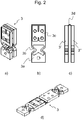
- FIG 2a, Figure 2b, Figure 2c, and Figure 2d illustrate a preferred embodiment of the rope end block 3 having first part 3' on a first side of said elevator rope and a second part 3" on a second side of said elevator rope.
- the rope end block 3 extends over said end face R' of said elevator rope.
- Rope end block 3 is a single piece structure where said first part 3' and a second part 3" of said rope end block 3 are connected with a middle part 3d of said rope end block 3.
- Rope end block 3 is manufactured from plastics or some other electrically non-conductive material.
- rope end block 3 is a single piece structure manufactured from plastics, preferably from thermoplastics polymer or thermosetting polymer.
- the rope end block 3 may be reinforced by non-metallic reinforcing fibers short cut or they may be continuous fibers. Hence the mechanical properties, particularly specific strength and stiffness of the rope end block 3 are improved.
- the rope end block 3 is preferably manufactured by extrusion, pultrusion, injection molding, blow molding, thermoforming, rotational molding, casting, foaming, compression molding or transfer molding, for instance.
- Said rope end block 3 pieces may also be manufactured from re-cycled plastics or other re-cycled materials.
- rope end block 3 comprises a first frame portion 3c attached to said elevator rope end and a second frame portion 3a attached to said wedge element 8, 8'.
- rope end block 3 comprises an elastic portion 3b between said first and second frame portions which elastic portion 3b allows relative movement of said first and second frame portions of said rope end block 3.
- Said elastic portion 3b is advantageously located outside of the second frame portion 3a of said rope end block 3 attached to said wedge element 8, 8'.
- rope end block 3 is attached to said elevator rope R end with fastening means. It is thus possible for the fastening means to pass through the openings in the first frame portion 3c of the rope end block 3.
- the fastening means can advantageously be made of metal or of some other suitable electrically conductive material.
- the fastening means are advantageously screws or bolts with nuts.
- the fastening to the rope can be done by drilling bores in the rope and fastening with screws or bolts.
- Elasticity of said rope end block 3 can also be arranged by sizing and designing the openings of the first frame portion 3c of the rope end block 3 to have an oval shape, for instance.
- Said rope end block 3 is attached to a wedge element 8, 8' with fastening means 10, 10'. It is thus possible for the fastening means 10, 10' to pass through the openings in the second frame portion 3a of the rope end block 3.
- the fastening means 10, 10' can advantageously be made of metal or of some other mechanically suitable material.
- the fastening means 10, 10' are advantageously screws or bolts. Fastening to the wedge element can be done by drilling bores in the wedge element 8, 8' and fastening with screws or bolts.
- said rope end block 3 comprises one or more short circuit elements attached to said rope end block 3 with fastening means. It is thus possible for the fastening means to pass through the openings in the short circuit elements.
- the short circuit elements such as short circuit plates as well as the fastening means are advantageously made of metal or of some other suitable electrically conductive material.
- the fastening means are advantageously screws or bolts. The fastening to the rope is done by drilling bores in the rope and fastening with screws or bolts.
- the fastening means for attaching short circuit elements are advantageously the same screws or bolts used to attach the rope end block 3 to the rope.
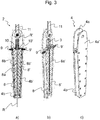
- FIG 3a and Figure 3b illustrate a preferred embodiment of the rope terminal assembly 2 with two wedge elements 8, 8' and Figure 3c illustrates a preferred embodiment of the rope terminal assembly 2 wedge housing 4.
- a preferred embodiment of a rope terminal assembly 2 of an elevator fixing an elevator rope R to a fixing base such as an elevator unit, CW comprises an elevator rope R, whose width is larger than its thickness in a rope transverse direction, with at least one end having an end face R', a rope end block 3 attached to the rope end, two wedge elements 8, 8', a wedge housing 4.
- the rope terminal assembly 2 comprises a rope gap through which said elevator rope R passes and said wedge element 8, 8' is arranged to wedge between said rope R and said wedge housing 4, preferably between said rope R and the support sides 4b, 4b' of said wedge housing 4, thus locking said elevator rope in the gap, and said rope end block 3 is attached on said end face side R' of the elevator rope R with respect to the wedge element 8, 8'.
- said wedge element 8, 8' is an elongated element comprising a smooth contact surface portion 8b, 8b' and a rough or patterned contact surface portion 8a, 8a', said smooth contact surface portion 8b, 8b' being arranged against said wedge housing 4 and said rough or patterned contact surface 8a, 8a' being arranged against said elevator rope R surface.
- the wedge element 8, 8' also comprises a space for the rope end block 3 at the first end of the wedge element 8, 8'. It is thus possible for the fastening means 10, 10' of the rope end block 3 to be attached to the space of the wedge element 8, 8'.
- the space for the rope end block 3 is advantageously on the rough or patterned contact surface portion 8a, 8a' side of the first end of the wedge element 8, 8' and comprises a threaded opening for the fastening means.
- the wedge element 8, 8' is advantageously made of metal or of some other mechanically suitable material.
- Said wedge housing 4 comprises two elongated side elements 4a, 4a' and two elongated wedge support elements 4b, 4b', said side elements 4a, 4a' and said wedge support elements 4b, 4b' being attached together by welding or by gluing the side and wedge support elements together.
- the side elements 4a, 4a' comprise hollows and the wedge support elements 4b, 4b' comprise plugs on their sides that fit together for placing the sides together.
- said wedge housing 4 comprises one or more adjustable locking means 9, 9' which are arranged to lock said wedge elements 8, 8' in its position in said wedge housing element 4. It is possible for the locking means 9, 9' to pass through the openings in the support elements 4b, 4b' of the wedge housing element.
- the wedge housing side elements 4a, 4a' as well as the support elements 4b, 4b' are advantageously made of metal or of some other mechanically suitable material.
- the locking means 9, 9' are advantageously screws or bolts. Locking of the wedge elements is done by fastening with screws or bolts.
- Said rope terminal assembly 2 is fixed to said fixing base with a fixing rod 11 being fixed to said side elements 4a, 4a' with fixing means. It is possible for the fixing means of the fixing rod 11 to pass through the openings in the side elements 4a, 4a' of the wedge housing 4.
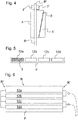
- FIG. 4 illustrates schematically an embodiment of a rope terminal assembly of an elevator attaching an elevator rope R to an elevator unit, which assembly comprises an elevator rope R, whose width is larger than its thickness in a rope transverse direction, with at least one end having an end face R', a rope end block 3 attached to the rope end R', one wedge element 8, and a wedge housing 4.
- the rope terminal assembly 2 comprises a rope gap through which said elevator rope R passes and said wedge element 8 is arranged to wedge between said rope R and said wedge housing 4, preferably between said rope R and the support side of said wedge housing 4, thus locking said elevator rope R in the gap, and said rope end block 3 is attached on said end face side R' of the elevator rope R with respect to the wedge element 8.
- said wedge housing 4 can be constructed as a single piece structure, a two piece structure, a three piece structure or a structure being constructed from several elements that form said rope gap for the rope and support for one or more wedge elements.
- FIG. 5 illustrates a preferred embodiment of a rope R cross section as described in connection with one of Figures 1 , 3 , and 4 used as a suspension and/or transmission rope R of an elevator, particularly a passenger elevator.
- at least one rope R but preferably a number of ropes R is constructed such that the width of the rope is larger than its thickness in a transverse direction of the rope R and fitted to support and move an elevator car, said rope R comprising a load-bearing part 12a, 12b, 12c, 12d made of composite material, which composite material comprises reinforcing fibers f, which consist of untwisted unidirectional carbon fibers, in a polymer matrix oriented in the lengthwise direction of the rope.
- the suspension rope R is most preferably secured by one end to the elevator car 1 and by the other end to a counterweight CW, but it is applicable for use in elevators without counterweight as well.
- the rope R described is also applicable for use as a suspension rope R in an elevator with a 1:2 suspension ratio.
- the rope R is particularly well suited for use as a suspension and transmission rope R in an elevator having a large lifting height, preferably an elevator having a lifting height of over 100 meters, most preferably 150-800 meters.
- the rope R defined can also be used to implement a new elevator without a compensating rope C, or to convert an old elevator into one without a compensating rope C.
- Figure 6 illustrates a preferred embodiment of an electrical model of the elevator rope condition monitoring arrangement, especially for the rope R part of said rope condition monitoring means, connected to the rope R via the rope end block 3 of the rope terminal assembly 2.
- the elevator comprises a light-weight rope R comprising one or more, preferably at least four unidirectional carbon fiber-reinforced-polymer load-bearing parts 12a, 12b, 12c, 12d as shown in Figure 6 covered with polyurethane coating p.
- the rope R is electrically modeled as four resistors. Preferred solution is to measure one rope R as a single resistance.
- the polymer layer pof the ropes R may comprise edges/corners more starkly rounded than those illustrated or edges/corners not rounded at all.
- the load-bearing part/parts 12a, 12b, 12c, 12d in the embodiments can be arranged to cover most of the cross-section of the rope R.
- the sheath-like polymer layer p surrounding the load-bearing part/parts 12a, 12b, 12c, 12d is made thinner as compared to the thickness of the load-bearing part 12a, 12b, 12c, 12d, in the thickness-wise direction of the rope R.
- the matrix polymer in which the reinforcing fibers f are distributed may comprise - mixed in the basic matrix polymer, such as e.g. epoxy - auxiliary materials, such as e.g. reinforcements, fillers, colors, fire retardants, stabilizers or corresponding agents.
- the polymer matrix preferably does not consist of elastomer
- the invention can also be utilized using an elastomer matrix.
- the fibers f need not necessarily be round in cross-section, but they may have some other cross-sectional shape.
- auxiliary materials such as e.g. reinforcements, fillers, colors, fire retardants, stabilizers or corresponding agents, may be mixed in the basic polymer of the layer p, e.g. in polyurethane.
- the invention can also be applied in elevators designed for hoisting heights other than those considered above.
Landscapes
- Engineering & Computer Science (AREA)
- General Engineering & Computer Science (AREA)
- Mechanical Engineering (AREA)
- Lift-Guide Devices, And Elevator Ropes And Cables (AREA)
- Ropes Or Cables (AREA)
- Maintenance And Inspection Apparatuses For Elevators (AREA)
Claims (10)
- Seilanschluss-Einrichtung (2) und ein Seil (R), mittels welcher Einrichtung das Seil an eine Basis, wie beispielsweise eine Aufzugs-Einheit oder andere Hubmaschine fixiert werden kann,
wobei in einer Seil-Querrichtung die Breite des Seiles größer ist als dessen Dicke, mit ferner mindestens einem Ende mit End-Stirnfläche (R'),
wobei die Einrichtung (2)- einen Seil-Endblock (3), der an den Seilanschluss befestigbar ist,- ein oder mehrere Keilelemente (8, 8') auf der Seite der besagten End-Stirnfläche (R') des Aufzugsseiles (R) des/der Keilelement(e) (8, 8'),- ein Keil-Gehäuse (4),- und einen Seilspalt aufweist, durch den das Aufzugsseil (R) durchführbar ist, und wobei das Keilelement (8, 8') dazu dient, zwischen dem Seil (R) und dem Keilgehäuse (4) zu verkeilen, womit das Aufzugsseil (R) in dem Spalt arretierbar ist,dadurch gekennzeichnet, dass das Aufzugsseil (R) elektrisch an eine Seilzustands-Überwachungseinrichtung via dem Seil-Endblock (3) angeschlossen ist, aufweisend ein oder mehrere elektrisch leitfähige Kurzschluss-Elemente sowie Befestigungsmittel, wobei die Befestigungsmittel Schrauben oder Bolzen sind, und ein Befestigen des Seiles durch Bohren von Löchern in das Seil unter Festlegen besagter Schrauben oder Bolzen erfolgt, und die Befestigungsmittel zum Festlegen der Kurzschlusselemente dieselben Schrauben oder Bolzen sind, wie sie zum Festlegen des Seil-Endblocks verwendet werden. - Seilanschluss-Einrichtung (2) gemäß Anspruch 1, dadurch gekennzeichnet, dass das Aufzugsseil (R) aus einem kohlenstofffaserverstärkten Polymer-Verbundmaterial gefertigt ist.
- Seilanschluss-Einrichtung (2) gemäß einem der vorangehenden Ansprüche, dadurch gekennzeichnet, dass das Aufzugsseil lasttragende Teile (12a, 12b, 12c, 12d) aus kohlenstoffverstärktem Polymer aufweist, an die die Seilzustands-Überwachungsmittel mit elektrisch leitenden Feststellmitteln angeschlossen sind.
- Aufzug, der zum Transportieren von Fahrgästen und/oder Materialgut geeignet ist, welche Aufzug aufweist:- einen Schacht (S),- mindestens eine Aufzugseinheit (1, CW), die in dem Schacht (S) bewegbar ist, mit mindestens einer Aufzugskabine (1),- Hebemittel, die eine Hebevorrichtung (M) und ein oder mehrere Aufzugsseile (R, C) aufweisen, die an die mindestens eine Aufzugseinheit (1, CW) angeschlossen sind,dadurch gekennzeichnet, dass das besagte Aufzugsseil (R, C) an eine Befestigungsbasis, wie beispielsweise eine Aufzugseinheit (1, CW) mit einer Seilanschluss-Einrichtung (2) gemäß einem der Ansprüche 1 bis 3 fixiert ist.
- Aufzug gemäß dem vorangehenden Anspruch 4, dadurch gekennzeichnet, dass der Aufzug Seilzustands-Überwachungsmittel aufweist, die via dem Seil-Endblock (3) an die lasttragenden Teile (12a, 12b, 12,c, 12d) des Aufzugsseils (R, C) angeschlossen sind.
- Aufzug gemäß einem der vorangehenden Ansprüche 4 oder 5, dadurch gekennzeichnet, dass der Aufzug Seilzustands-Überwachungsmittel aufweist, die eine Seilzustands-Überwachungsvorrichtung umfassen, mit der ein elektrisches Signal des Aufzugsseiles (R, C) überwacht und an eine Aufzugssteuerung übermittelt wird, und zwar zu vorbestimmten Zeitintervallen.
- Aufzug gemäß einem der vorangehenden Ansprüche 4 bis 6, dadurch gekennzeichnet, dass der Aufzug Seilzustands-Überwachungsmittel aufweist, wobei, falls ein Fehlersignal von den Seilzustands-Überwachungsmitteln an eine Aufzugssteuerung übertragen wird, der Aufzugsbetrieb geändert oder der Aufzug außer Betrieb gesetzt wird.
- Aufzug gemäß einem der vorangehenden Ansprüche 4 bis 7, dadurch gekennzeichnet, dass das Aufzugsseil (R, C) lasttragende Teile (12a, 12b, 12c, 12d) aufweist, die aus einem Matrix-Verbund-Material aus faserverstärktem Polymer gefertigt sind, wie beispielsweise einem kohlenstofffaserverstärktem Polymer-Matrix-Verbund, vorzugsweise einem Verbund aus unidirektionaler kohlenstofffaserverstärkter Polymer-Matrix.
- Aufzug gemäß einem der vorangehenden Ansprüche 4 bis 8, dadurch gekennzeichnet, dass der Aufzug Seilzustands-Überwachungsmittel aufweist, die zum Messen eines elektrischen Widerstandes zwischen dem ersten Punkt und dem zweiten Punkt des Aufzugseiles (R, C) verwendet werden, erstmalig während einer Aufzugsinstallation, und zum zweiten Mal, wenn der Aufzug zum Transportieren von Fahrgästen und/oder Materialgut verwendet worden ist.
- Aufzug gemäß dem vorangehenden Anspruch 9, dadurch gekennzeichnet, dass der besagte erste Punkt und der zweite Punkt Punkte eines nicht-metallischen, lasttragenden Teils (12a, 12b, 12c, 12d) des Aufzugsseiles (R, C) sind, oder Punkte mehrerer elektrisch verbundener, nicht-metallischer lasttragender Teile (12a, 12b, 12c, 12d) des Aufzugsseiles (R, C).
Applications Claiming Priority (2)
| Application Number | Priority Date | Filing Date | Title |
|---|---|---|---|
| FI20126393A FI124543B (en) | 2012-12-30 | 2012-12-30 | Rope clamp assembly and elevator |
| EP13196524.6A EP2749520B1 (de) | 2012-12-30 | 2013-12-10 | Seilendgerätanordnung und Aufzug |
Related Parent Applications (2)
| Application Number | Title | Priority Date | Filing Date |
|---|---|---|---|
| EP13196524.6A Division-Into EP2749520B1 (de) | 2012-12-30 | 2013-12-10 | Seilendgerätanordnung und Aufzug |
| EP13196524.6A Division EP2749520B1 (de) | 2012-12-30 | 2013-12-10 | Seilendgerätanordnung und Aufzug |
Publications (2)
| Publication Number | Publication Date |
|---|---|
| EP2933218A1 EP2933218A1 (de) | 2015-10-21 |
| EP2933218B1 true EP2933218B1 (de) | 2017-02-08 |
Family
ID=49766920
Family Applications (2)
| Application Number | Title | Priority Date | Filing Date |
|---|---|---|---|
| EP15168641.7A Not-in-force EP2933218B1 (de) | 2012-12-30 | 2013-12-10 | Seilanschlussanordnung einschliesslich eines seilzustandsüberwachungsmittels |
| EP13196524.6A Active EP2749520B1 (de) | 2012-12-30 | 2013-12-10 | Seilendgerätanordnung und Aufzug |
Family Applications After (1)
| Application Number | Title | Priority Date | Filing Date |
|---|---|---|---|
| EP13196524.6A Active EP2749520B1 (de) | 2012-12-30 | 2013-12-10 | Seilendgerätanordnung und Aufzug |
Country Status (9)
| Country | Link |
|---|---|
| US (1) | US9422134B2 (de) |
| EP (2) | EP2933218B1 (de) |
| JP (1) | JP5572756B2 (de) |
| CN (1) | CN103912632B (de) |
| AU (1) | AU2013273614B2 (de) |
| BR (1) | BR102013032986B1 (de) |
| ES (2) | ES2543955T3 (de) |
| FI (1) | FI124543B (de) |
| SG (1) | SG2013093786A (de) |
Families Citing this family (49)
| Publication number | Priority date | Publication date | Assignee | Title |
|---|---|---|---|---|
| EP2925656B1 (de) * | 2012-11-29 | 2019-07-31 | Inventio AG | Aufzugsanlage |
| EP2969875B1 (de) * | 2013-03-15 | 2018-11-28 | Otis Elevator Company | System und verfahren zur überwachung von drahtseilen |
| EP2851325B1 (de) * | 2013-09-24 | 2016-09-14 | KONE Corporation | Seilanschlussanordnung und Aufzug |
| EP2860142B1 (de) * | 2013-10-10 | 2016-09-14 | KONE Corporation | Seilendgerätanordnung und Aufzug |
| EP2878563B1 (de) * | 2013-11-29 | 2017-03-22 | KONE Corporation | Seilendgerätanordnung und Aufzug |
| EP2910509B1 (de) * | 2014-02-19 | 2016-11-02 | KONE Corporation | Seilklemme für eine Aufzugsanlage. |
| FI126182B (en) * | 2014-06-17 | 2016-07-29 | Kone Corp | Method and arrangement for monitoring the condition of an elevator rope |
| JP6466659B2 (ja) | 2014-06-24 | 2019-02-06 | 株式会社ユーシン | ドアロック装置 |
| EP3028979A1 (de) * | 2014-12-01 | 2016-06-08 | KONE Corporation | Verfahren zur Herstellung einer elektrischen Kontaktanordnung und Kontaktanordnung |
| ES2707982T3 (es) * | 2014-12-19 | 2019-04-08 | Otis Elevator Co | Terminación de correa para ascensor |
| EP3040301B1 (de) | 2014-12-30 | 2017-07-05 | KONE Corporation | Seilabschlussanordnung und Hebevorrichtung |
| EP3242849B1 (de) * | 2015-01-09 | 2020-07-01 | Otis Elevator Company | Lasttragelement für aufzugssystem |
| EP3048076B1 (de) * | 2015-01-21 | 2017-04-19 | KONE Corporation | Seilhebewerkzeug und Seilhebeeinrichtung |
| EP3053867A1 (de) | 2015-02-03 | 2016-08-10 | KONE Corporation | Seilanschlussanordnung, Anordnung zur Zustandsüberwachung eines Aufzugsseils und Aufzug |
| CN105984773B (zh) * | 2015-02-28 | 2020-06-12 | 通力股份公司 | 用于检测多个电梯绳索的总载荷的绳索载荷检测装置 |
| EP3070042A1 (de) * | 2015-03-16 | 2016-09-21 | Kone Corporation | Seilanschlussanordnung und Aufzug |
| EP3103754A1 (de) * | 2015-06-08 | 2016-12-14 | Kone Corporation | Seilanschlussanordnung und aufzug |
| EP3127850A1 (de) * | 2015-08-07 | 2017-02-08 | Kone Corporation | Verfahren für eine seilanschlussanordnung und aufzug |
| EP3135621B1 (de) | 2015-08-31 | 2018-06-13 | KONE Corporation | Verfahren, anordnung und aufzug |
| EP3163119A1 (de) | 2015-10-29 | 2017-05-03 | KONE Corporation | Verfahren, seilanordnung und aufzug |
| EP3176117A1 (de) | 2015-12-03 | 2017-06-07 | KONE Corporation | Seilanschlussvorrichtung, seilanschlussanordnung und aufzug |
| EP3187451A1 (de) | 2016-01-04 | 2017-07-05 | KONE Corporation | Verfahren zur herstellung einer seilterminalausrüstung, verfahren zur herstellung einer seilterminalanordnung und aufzug |
| EP3199482A1 (de) | 2016-02-01 | 2017-08-02 | Kone Corporation | Seilanschlussvorrichtung, seilanschlussanordnung und aufzug |
| EP3248926A1 (de) | 2016-05-24 | 2017-11-29 | KONE Corporation | Aufzugsanordnung und verfahren |
| US10131521B2 (en) | 2016-10-24 | 2018-11-20 | Thyssenkrupp Elevator Ag | Belt end termination with a cone clamp |
| EP3318525B1 (de) | 2016-11-07 | 2020-06-10 | Otis Elevator Company | Aufhängungselementabschluss eines aufzugssystems |
| CN108147254B (zh) | 2016-12-02 | 2020-12-01 | 奥的斯电梯公司 | 具有改进的压力分布的电梯系统悬挂构件端接部 |
| US10183841B2 (en) * | 2016-12-12 | 2019-01-22 | Thyssenkrup Elevator Ag | Multi-wedge end termination for an elevator system |
| CN108217384B (zh) | 2016-12-14 | 2021-07-06 | 奥的斯电梯公司 | 具有约束的电梯系统悬挂构件端接 |
| EP3348510A1 (de) * | 2017-01-12 | 2018-07-18 | KONE Corporation | Abschlussvorrichtung für ein seil einer hebevorrichtung |
| US11111105B2 (en) * | 2017-01-26 | 2021-09-07 | Otis Elevator Company | Compliant shear layer for elevator termination |
| DE202017102097U1 (de) | 2017-04-07 | 2017-05-08 | Kone Corporation | Keilelement für eine Seilterminalanordnung |
| US10189678B2 (en) | 2017-04-11 | 2019-01-29 | Thyssenkrupp Elevator Ag | Elevator strip bonded end termination |
| AU2018202597B2 (en) | 2017-04-20 | 2023-11-16 | Otis Elevator Company | Tension member for elevator system belt |
| US20190338593A1 (en) | 2017-07-17 | 2019-11-07 | Safeworks, Llc | Integrated climb assist and fall arrest systems and methods |
| US10562740B2 (en) * | 2017-09-15 | 2020-02-18 | Otis Elevator Company | Elevator load bearing termination assembly for carbon fiber belt |
| CN111712652B (zh) * | 2017-09-20 | 2022-06-03 | 安全工程有限责任公司 | 绳索连接系统、装置和方法 |
| US20190100408A1 (en) * | 2017-09-29 | 2019-04-04 | Otis Elevator Company | Rope deterioration detection |
| US10723592B2 (en) * | 2017-10-19 | 2020-07-28 | Thyssenkrupp Elevator Ag | System and method for monitoring an elevator belt |
| KR20190053466A (ko) | 2017-11-10 | 2019-05-20 | 다이텍연구원 | 탄소섬유강화복합재로 이루어진 엘리베이터 로프의 고정용 클램프 |
| US11299370B2 (en) | 2018-06-29 | 2022-04-12 | Otis Elevator Company | Data transmission via elevator system tension member |
| US20210245996A1 (en) * | 2018-07-20 | 2021-08-12 | Mitsubishi Electric Corporation | Elevator rope terminal structure |
| CN109466989B (zh) * | 2018-12-29 | 2021-01-22 | 江苏兴华胶带股份有限公司 | 一种载人高速升降电梯炭纤维增强耐寒难燃平衡补偿链 |
| EP3725725B1 (de) | 2019-04-17 | 2022-02-09 | KONE Corporation | Seilgreifelement einer hebevorrichtung, seilgreifvorrichtung, endgeräteanordnung und hebevorrichtung |
| CN114761346B (zh) * | 2019-12-20 | 2024-09-13 | 三菱电机株式会社 | 电梯主绳索末端结构体、电梯装置和电梯装置的组装方法 |
| CN114572794B (zh) * | 2022-03-01 | 2023-08-22 | 宁波市特种设备检验研究院 | 一种智能电梯钢带断裂检测装置 |
| EP4450444A1 (de) | 2023-04-18 | 2024-10-23 | KONE Corporation | Verfahren und überwachungsanordnung |
| US12091287B1 (en) * | 2023-08-01 | 2024-09-17 | Otis Elevator Company | Elevator connector with angled interface |
| CN118289604B (zh) * | 2024-06-06 | 2024-08-20 | 安徽省特种设备检测院 | 一种电梯升降过程中的震动检测装置 |
Family Cites Families (34)
| Publication number | Priority date | Publication date | Assignee | Title |
|---|---|---|---|---|
| DE2136540A1 (de) * | 1971-07-22 | 1973-02-01 | Rudolf Dr Ing Vogel | Aufzug |
| DE2457298A1 (de) * | 1974-11-29 | 1976-06-10 | Banyaszati Tervezoe | Seilsystem und seilklemme zu hubvorrichtungen, besonders zu treibscheibenschachtfoerderanlagen |
| FR2293392A1 (fr) * | 1974-12-04 | 1976-07-02 | December 4 Drotmuevek | Cables et dispositifs d'arret de cables pour systeme de levage en particulier koepe |
| JPS5839754B2 (ja) * | 1978-03-14 | 1983-09-01 | フエプス企業株式会社 | 平型ケ−ブルの懸吊支持装置 |
| US4845814A (en) * | 1987-04-13 | 1989-07-11 | Crosby Group, Inc. | Wedge socket |
| GB2255354B (en) * | 1991-05-03 | 1994-09-28 | Bridon Plc | Strand anchorage |
| JP2533859Y2 (ja) * | 1992-11-02 | 1997-04-23 | 株式会社クボタ | 巻上装置用ワイヤのエンド構造 |
| WO1998029327A1 (en) * | 1996-12-30 | 1998-07-09 | Kone Corporation | Elevator rope arrangement |
| US6256841B1 (en) * | 1998-12-31 | 2001-07-10 | Otis Elevator Company | Wedge clamp type termination for elevator tension member |
| US6633159B1 (en) * | 1999-03-29 | 2003-10-14 | Otis Elevator Company | Method and apparatus for magnetic detection of degradation of jacketed elevator rope |
| IL140043A (en) * | 1999-12-21 | 2006-07-05 | Inventio Ag | Synthetic ropes are tested for safety that connect in contact |
| US6484368B1 (en) * | 2000-01-11 | 2002-11-26 | Otis Elevator Company | Flexible flat tension member termination device |
| CN1184132C (zh) * | 2000-08-24 | 2005-01-12 | 三菱电机株式会社 | 电梯用合成纤维绳 |
| NO323985B1 (no) * | 2000-12-14 | 2007-07-30 | Fmc Kongsberg Subsea As | Koblingsanordning |
| US20020194935A1 (en) * | 2001-06-26 | 2002-12-26 | Arthur Clarke | Tensile load sensing belt |
| US20030121729A1 (en) * | 2002-01-02 | 2003-07-03 | Guenther Heinz | Lift belt and system |
| CN1292972C (zh) * | 2002-11-08 | 2007-01-03 | 三菱电机株式会社 | 电梯装置 |
| JP2005139001A (ja) * | 2003-11-04 | 2005-06-02 | Inventio Ag | 支持手段を点検する方法および装置 |
| ES2360527T3 (es) * | 2004-03-16 | 2011-06-06 | Otis Elevator Company | Dispositivo conector eléctrico para utilizar con miembros de soporte de carga de ascensores. |
| CN1926047B (zh) * | 2004-03-16 | 2010-06-23 | 奥蒂斯电梯公司 | 用于电梯带的电连接器和约束装置 |
| JP4820815B2 (ja) * | 2004-03-16 | 2011-11-24 | オーチス エレベータ カンパニー | エレベータ荷重支持部材の状態を監視する電気信号適用方法 |
| ATE417804T1 (de) * | 2004-09-13 | 2009-01-15 | Inventio Ag | Tragmittelendverbindung zur befestigung eines endes eines tragmittels in einer aufzugsanlage und verfahren zur befestigung eines endes eines tragmittels in einer aufzugsanlage |
| WO2006049226A1 (en) * | 2004-11-02 | 2006-05-11 | Toray International, Inc. | Fiber sling and method for evaluating its performance |
| ES2428374T3 (es) * | 2006-12-04 | 2013-11-07 | Inventio Ag | Cable de fibras sintéticas |
| ES2341930B1 (es) * | 2007-08-03 | 2011-05-25 | Orona, S. Coop | Elemento de fijacion compacto para cables de elevadores y aparato elevador que incorpora dichos elementos de fijacion. |
| GB2458001B (en) | 2008-01-18 | 2010-12-08 | Kone Corp | An elevator hoist rope, an elevator and method |
| JP5448374B2 (ja) * | 2008-06-11 | 2014-03-19 | 株式会社日立製作所 | ロープ端末固定装置 |
| BRPI0922055A2 (pt) * | 2008-11-19 | 2015-12-22 | Inventio Ag | correia de sustentação de instalação de elevador. |
| FI125142B (fi) * | 2009-07-08 | 2015-06-15 | Kone Corp | Nostolaitteen köysi, köysijärjestely, hissi ja menetelmä |
| EP2534082B1 (de) * | 2010-02-10 | 2018-06-27 | Otis Elevator Company | Gurt eines aufzugssystems mit daran fixierten verbindungselementen |
| WO2012030332A1 (en) * | 2010-09-01 | 2012-03-08 | Otis Elevator Company | Resistance-based monitoring system and method |
| CN202022638U (zh) * | 2011-04-26 | 2011-11-02 | 江南嘉捷电梯股份有限公司 | 电梯轿架绳头板的设置结构 |
| US20130270042A1 (en) * | 2012-04-12 | 2013-10-17 | Inventio Ag | Determining states of elevator components |
| FI124542B (en) * | 2012-12-30 | 2014-10-15 | Kone Corp | Method and arrangement of the condition of the lift rope |
-
2012
- 2012-12-30 FI FI20126393A patent/FI124543B/en active IP Right Grant
-
2013
- 2013-12-10 EP EP15168641.7A patent/EP2933218B1/de not_active Not-in-force
- 2013-12-10 EP EP13196524.6A patent/EP2749520B1/de active Active
- 2013-12-10 ES ES13196524.6T patent/ES2543955T3/es active Active
- 2013-12-10 ES ES15168641.7T patent/ES2615905T3/es active Active
- 2013-12-17 AU AU2013273614A patent/AU2013273614B2/en active Active
- 2013-12-18 SG SG2013093786A patent/SG2013093786A/en unknown
- 2013-12-20 BR BR102013032986-0A patent/BR102013032986B1/pt not_active IP Right Cessation
- 2013-12-23 CN CN201310717174.5A patent/CN103912632B/zh active Active
- 2013-12-27 US US14/141,601 patent/US9422134B2/en active Active
- 2013-12-27 JP JP2013271727A patent/JP5572756B2/ja not_active Expired - Fee Related
Also Published As
| Publication number | Publication date |
|---|---|
| AU2013273614B2 (en) | 2018-05-24 |
| EP2749520A3 (de) | 2014-10-08 |
| EP2749520B1 (de) | 2015-07-08 |
| CN103912632A (zh) | 2014-07-09 |
| FI20126393L (fi) | 2014-07-01 |
| SG2013093786A (en) | 2014-07-30 |
| JP2014129182A (ja) | 2014-07-10 |
| HK1199086A1 (zh) | 2015-06-19 |
| CN103912632B (zh) | 2016-05-04 |
| US9422134B2 (en) | 2016-08-23 |
| BR102013032986A2 (pt) | 2014-11-04 |
| US20140182975A1 (en) | 2014-07-03 |
| ES2615905T3 (es) | 2017-06-08 |
| JP5572756B2 (ja) | 2014-08-13 |
| BR102013032986B1 (pt) | 2021-07-20 |
| FI124543B (en) | 2014-10-15 |
| ES2543955T3 (es) | 2015-08-26 |
| EP2933218A1 (de) | 2015-10-21 |
| AU2013273614A1 (en) | 2014-07-17 |
| EP2749520A2 (de) | 2014-07-02 |
Similar Documents
| Publication | Publication Date | Title |
|---|---|---|
| AU2013273614B2 (en) | A rope terminal assembly and an elevator | |
| US10280039B2 (en) | Rope terminal assembly and an elevator | |
| US10081516B2 (en) | Rope terminal assembly and an elevator | |
| EP2860142B1 (de) | Seilendgerätanordnung und Aufzug | |
| EP2749521B1 (de) | Verfahren zur Zustandsüberwachung eines Aufzugseils | |
| HK1199086B (en) | A rope terminal assembly and an elevator | |
| HK1219085B (zh) | 绳索端头组件和电梯 | |
| HK1207051B (zh) | 绳索端组件和电梯 | |
| HK1205994B (zh) | 绳索端子组件和电梯 |
Legal Events
| Date | Code | Title | Description |
|---|---|---|---|
| PUAI | Public reference made under article 153(3) epc to a published international application that has entered the european phase |
Free format text: ORIGINAL CODE: 0009012 |
|
| AC | Divisional application: reference to earlier application |
Ref document number: 2749520 Country of ref document: EP Kind code of ref document: P |
|
| AK | Designated contracting states |
Kind code of ref document: A1 Designated state(s): AL AT BE BG CH CY CZ DE DK EE ES FI FR GB GR HR HU IE IS IT LI LT LU LV MC MK MT NL NO PL PT RO RS SE SI SK SM TR |
|
| 17P | Request for examination filed |
Effective date: 20160212 |
|
| RBV | Designated contracting states (corrected) |
Designated state(s): AL AT BE BG CH CY CZ DE DK EE ES FI FR GB GR HR HU IE IS IT LI LT LU LV MC MK MT NL NO PL PT RO RS SE SI SK SM TR |
|
| GRAP | Despatch of communication of intention to grant a patent |
Free format text: ORIGINAL CODE: EPIDOSNIGR1 |
|
| RIC1 | Information provided on ipc code assigned before grant |
Ipc: B66B 7/12 20060101ALN20160825BHEP Ipc: B66C 1/18 20060101ALI20160825BHEP Ipc: B66B 7/06 20060101ALN20160825BHEP Ipc: F16G 11/04 20060101ALI20160825BHEP Ipc: B66B 7/08 20060101AFI20160825BHEP |
|
| INTG | Intention to grant announced |
Effective date: 20160909 |
|
| GRAS | Grant fee paid |
Free format text: ORIGINAL CODE: EPIDOSNIGR3 |
|
| RIN1 | Information on inventor provided before grant (corrected) |
Inventor name: IKONEN, ANTTI Inventor name: HALLIKAINEN, PEKKA Inventor name: LUOMA, JANI Inventor name: PELTO-HUIKKO, RAIMO |
|
| RAP1 | Party data changed (applicant data changed or rights of an application transferred) |
Owner name: KONE CORPORATION |
|
| GRAA | (expected) grant |
Free format text: ORIGINAL CODE: 0009210 |
|
| AC | Divisional application: reference to earlier application |
Ref document number: 2749520 Country of ref document: EP Kind code of ref document: P |
|
| AK | Designated contracting states |
Kind code of ref document: B1 Designated state(s): AL AT BE BG CH CY CZ DE DK EE ES FI FR GB GR HR HU IE IS IT LI LT LU LV MC MK MT NL NO PL PT RO RS SE SI SK SM TR |
|
| REG | Reference to a national code |
Ref country code: GB Ref legal event code: FG4D |
|
| REG | Reference to a national code |
Ref country code: CH Ref legal event code: EP Ref country code: AT Ref legal event code: REF Ref document number: 866775 Country of ref document: AT Kind code of ref document: T Effective date: 20170215 |
|
| REG | Reference to a national code |
Ref country code: IE Ref legal event code: FG4D |
|
| REG | Reference to a national code |
Ref country code: DE Ref legal event code: R096 Ref document number: 602013017421 Country of ref document: DE |
|
| REG | Reference to a national code |
Ref country code: ES Ref legal event code: FG2A Ref document number: 2615905 Country of ref document: ES Kind code of ref document: T3 Effective date: 20170608 |
|
| REG | Reference to a national code |
Ref country code: LT Ref legal event code: MG4D |
|
| REG | Reference to a national code |
Ref country code: NL Ref legal event code: MP Effective date: 20170208 |
|
| REG | Reference to a national code |
Ref country code: AT Ref legal event code: MK05 Ref document number: 866775 Country of ref document: AT Kind code of ref document: T Effective date: 20170208 |
|
| PG25 | Lapsed in a contracting state [announced via postgrant information from national office to epo] |
Ref country code: HR Free format text: LAPSE BECAUSE OF FAILURE TO SUBMIT A TRANSLATION OF THE DESCRIPTION OR TO PAY THE FEE WITHIN THE PRESCRIBED TIME-LIMIT Effective date: 20170208 Ref country code: GR Free format text: LAPSE BECAUSE OF FAILURE TO SUBMIT A TRANSLATION OF THE DESCRIPTION OR TO PAY THE FEE WITHIN THE PRESCRIBED TIME-LIMIT Effective date: 20170509 Ref country code: NO Free format text: LAPSE BECAUSE OF FAILURE TO SUBMIT A TRANSLATION OF THE DESCRIPTION OR TO PAY THE FEE WITHIN THE PRESCRIBED TIME-LIMIT Effective date: 20170508 Ref country code: FI Free format text: LAPSE BECAUSE OF FAILURE TO SUBMIT A TRANSLATION OF THE DESCRIPTION OR TO PAY THE FEE WITHIN THE PRESCRIBED TIME-LIMIT Effective date: 20170208 Ref country code: LT Free format text: LAPSE BECAUSE OF FAILURE TO SUBMIT A TRANSLATION OF THE DESCRIPTION OR TO PAY THE FEE WITHIN THE PRESCRIBED TIME-LIMIT Effective date: 20170208 |
|
| PG25 | Lapsed in a contracting state [announced via postgrant information from national office to epo] |
Ref country code: PT Free format text: LAPSE BECAUSE OF FAILURE TO SUBMIT A TRANSLATION OF THE DESCRIPTION OR TO PAY THE FEE WITHIN THE PRESCRIBED TIME-LIMIT Effective date: 20170608 Ref country code: BG Free format text: LAPSE BECAUSE OF FAILURE TO SUBMIT A TRANSLATION OF THE DESCRIPTION OR TO PAY THE FEE WITHIN THE PRESCRIBED TIME-LIMIT Effective date: 20170508 Ref country code: LV Free format text: LAPSE BECAUSE OF FAILURE TO SUBMIT A TRANSLATION OF THE DESCRIPTION OR TO PAY THE FEE WITHIN THE PRESCRIBED TIME-LIMIT Effective date: 20170208 Ref country code: SE Free format text: LAPSE BECAUSE OF FAILURE TO SUBMIT A TRANSLATION OF THE DESCRIPTION OR TO PAY THE FEE WITHIN THE PRESCRIBED TIME-LIMIT Effective date: 20170208 Ref country code: NL Free format text: LAPSE BECAUSE OF NON-PAYMENT OF DUE FEES Effective date: 20170208 Ref country code: RS Free format text: LAPSE BECAUSE OF FAILURE TO SUBMIT A TRANSLATION OF THE DESCRIPTION OR TO PAY THE FEE WITHIN THE PRESCRIBED TIME-LIMIT Effective date: 20170208 Ref country code: AT Free format text: LAPSE BECAUSE OF FAILURE TO SUBMIT A TRANSLATION OF THE DESCRIPTION OR TO PAY THE FEE WITHIN THE PRESCRIBED TIME-LIMIT Effective date: 20170208 |
|
| PG25 | Lapsed in a contracting state [announced via postgrant information from national office to epo] |
Ref country code: CZ Free format text: LAPSE BECAUSE OF FAILURE TO SUBMIT A TRANSLATION OF THE DESCRIPTION OR TO PAY THE FEE WITHIN THE PRESCRIBED TIME-LIMIT Effective date: 20170208 Ref country code: IT Free format text: LAPSE BECAUSE OF FAILURE TO SUBMIT A TRANSLATION OF THE DESCRIPTION OR TO PAY THE FEE WITHIN THE PRESCRIBED TIME-LIMIT Effective date: 20170208 Ref country code: EE Free format text: LAPSE BECAUSE OF FAILURE TO SUBMIT A TRANSLATION OF THE DESCRIPTION OR TO PAY THE FEE WITHIN THE PRESCRIBED TIME-LIMIT Effective date: 20170208 Ref country code: RO Free format text: LAPSE BECAUSE OF FAILURE TO SUBMIT A TRANSLATION OF THE DESCRIPTION OR TO PAY THE FEE WITHIN THE PRESCRIBED TIME-LIMIT Effective date: 20170208 Ref country code: SK Free format text: LAPSE BECAUSE OF FAILURE TO SUBMIT A TRANSLATION OF THE DESCRIPTION OR TO PAY THE FEE WITHIN THE PRESCRIBED TIME-LIMIT Effective date: 20170208 |
|
| REG | Reference to a national code |
Ref country code: DE Ref legal event code: R097 Ref document number: 602013017421 Country of ref document: DE |
|
| PG25 | Lapsed in a contracting state [announced via postgrant information from national office to epo] |
Ref country code: SM Free format text: LAPSE BECAUSE OF FAILURE TO SUBMIT A TRANSLATION OF THE DESCRIPTION OR TO PAY THE FEE WITHIN THE PRESCRIBED TIME-LIMIT Effective date: 20170208 Ref country code: PL Free format text: LAPSE BECAUSE OF FAILURE TO SUBMIT A TRANSLATION OF THE DESCRIPTION OR TO PAY THE FEE WITHIN THE PRESCRIBED TIME-LIMIT Effective date: 20170208 Ref country code: DK Free format text: LAPSE BECAUSE OF FAILURE TO SUBMIT A TRANSLATION OF THE DESCRIPTION OR TO PAY THE FEE WITHIN THE PRESCRIBED TIME-LIMIT Effective date: 20170208 |
|
| PLBE | No opposition filed within time limit |
Free format text: ORIGINAL CODE: 0009261 |
|
| STAA | Information on the status of an ep patent application or granted ep patent |
Free format text: STATUS: NO OPPOSITION FILED WITHIN TIME LIMIT |
|
| REG | Reference to a national code |
Ref country code: FR Ref legal event code: PLFP Year of fee payment: 5 |
|
| 26N | No opposition filed |
Effective date: 20171109 |
|
| PG25 | Lapsed in a contracting state [announced via postgrant information from national office to epo] |
Ref country code: SI Free format text: LAPSE BECAUSE OF FAILURE TO SUBMIT A TRANSLATION OF THE DESCRIPTION OR TO PAY THE FEE WITHIN THE PRESCRIBED TIME-LIMIT Effective date: 20170208 |
|
| REG | Reference to a national code |
Ref country code: IE Ref legal event code: MM4A |
|
| PG25 | Lapsed in a contracting state [announced via postgrant information from national office to epo] |
Ref country code: LU Free format text: LAPSE BECAUSE OF NON-PAYMENT OF DUE FEES Effective date: 20171210 Ref country code: MT Free format text: LAPSE BECAUSE OF NON-PAYMENT OF DUE FEES Effective date: 20171210 |
|
| REG | Reference to a national code |
Ref country code: BE Ref legal event code: MM Effective date: 20171231 |
|
| PG25 | Lapsed in a contracting state [announced via postgrant information from national office to epo] |
Ref country code: IE Free format text: LAPSE BECAUSE OF NON-PAYMENT OF DUE FEES Effective date: 20171210 |
|
| PG25 | Lapsed in a contracting state [announced via postgrant information from national office to epo] |
Ref country code: BE Free format text: LAPSE BECAUSE OF NON-PAYMENT OF DUE FEES Effective date: 20171231 |
|
| PG25 | Lapsed in a contracting state [announced via postgrant information from national office to epo] |
Ref country code: HU Free format text: LAPSE BECAUSE OF FAILURE TO SUBMIT A TRANSLATION OF THE DESCRIPTION OR TO PAY THE FEE WITHIN THE PRESCRIBED TIME-LIMIT; INVALID AB INITIO Effective date: 20131210 Ref country code: MC Free format text: LAPSE BECAUSE OF FAILURE TO SUBMIT A TRANSLATION OF THE DESCRIPTION OR TO PAY THE FEE WITHIN THE PRESCRIBED TIME-LIMIT Effective date: 20170208 |
|
| PG25 | Lapsed in a contracting state [announced via postgrant information from national office to epo] |
Ref country code: CY Free format text: LAPSE BECAUSE OF FAILURE TO SUBMIT A TRANSLATION OF THE DESCRIPTION OR TO PAY THE FEE WITHIN THE PRESCRIBED TIME-LIMIT Effective date: 20170208 |
|
| PG25 | Lapsed in a contracting state [announced via postgrant information from national office to epo] |
Ref country code: MK Free format text: LAPSE BECAUSE OF FAILURE TO SUBMIT A TRANSLATION OF THE DESCRIPTION OR TO PAY THE FEE WITHIN THE PRESCRIBED TIME-LIMIT Effective date: 20170208 |
|
| PG25 | Lapsed in a contracting state [announced via postgrant information from national office to epo] |
Ref country code: TR Free format text: LAPSE BECAUSE OF FAILURE TO SUBMIT A TRANSLATION OF THE DESCRIPTION OR TO PAY THE FEE WITHIN THE PRESCRIBED TIME-LIMIT Effective date: 20170208 |
|
| PG25 | Lapsed in a contracting state [announced via postgrant information from national office to epo] |
Ref country code: AL Free format text: LAPSE BECAUSE OF FAILURE TO SUBMIT A TRANSLATION OF THE DESCRIPTION OR TO PAY THE FEE WITHIN THE PRESCRIBED TIME-LIMIT Effective date: 20170208 Ref country code: IS Free format text: LAPSE BECAUSE OF FAILURE TO SUBMIT A TRANSLATION OF THE DESCRIPTION OR TO PAY THE FEE WITHIN THE PRESCRIBED TIME-LIMIT Effective date: 20170608 |
|
| PGFP | Annual fee paid to national office [announced via postgrant information from national office to epo] |
Ref country code: FR Payment date: 20211224 Year of fee payment: 9 Ref country code: GB Payment date: 20211222 Year of fee payment: 9 Ref country code: DE Payment date: 20211210 Year of fee payment: 9 |
|
| PGFP | Annual fee paid to national office [announced via postgrant information from national office to epo] |
Ref country code: CH Payment date: 20211221 Year of fee payment: 9 |
|
| PGFP | Annual fee paid to national office [announced via postgrant information from national office to epo] |
Ref country code: ES Payment date: 20220222 Year of fee payment: 9 |
|
| REG | Reference to a national code |
Ref country code: DE Ref legal event code: R119 Ref document number: 602013017421 Country of ref document: DE |
|
| REG | Reference to a national code |
Ref country code: CH Ref legal event code: PL |
|
| GBPC | Gb: european patent ceased through non-payment of renewal fee |
Effective date: 20221210 |
|
| PG25 | Lapsed in a contracting state [announced via postgrant information from national office to epo] |
Ref country code: LI Free format text: LAPSE BECAUSE OF NON-PAYMENT OF DUE FEES Effective date: 20221231 Ref country code: GB Free format text: LAPSE BECAUSE OF NON-PAYMENT OF DUE FEES Effective date: 20221210 Ref country code: DE Free format text: LAPSE BECAUSE OF NON-PAYMENT OF DUE FEES Effective date: 20230701 Ref country code: CH Free format text: LAPSE BECAUSE OF NON-PAYMENT OF DUE FEES Effective date: 20221231 |
|
| PG25 | Lapsed in a contracting state [announced via postgrant information from national office to epo] |
Ref country code: FR Free format text: LAPSE BECAUSE OF NON-PAYMENT OF DUE FEES Effective date: 20221231 |
|
| REG | Reference to a national code |
Ref country code: ES Ref legal event code: FD2A Effective date: 20240129 |
|
| PG25 | Lapsed in a contracting state [announced via postgrant information from national office to epo] |
Ref country code: ES Free format text: LAPSE BECAUSE OF NON-PAYMENT OF DUE FEES Effective date: 20221211 |
|
| PG25 | Lapsed in a contracting state [announced via postgrant information from national office to epo] |
Ref country code: ES Free format text: LAPSE BECAUSE OF NON-PAYMENT OF DUE FEES Effective date: 20221211 |