EP2932952A1 - Surgical support system - Google Patents
Surgical support system Download PDFInfo
- Publication number
- EP2932952A1 EP2932952A1 EP15169611.9A EP15169611A EP2932952A1 EP 2932952 A1 EP2932952 A1 EP 2932952A1 EP 15169611 A EP15169611 A EP 15169611A EP 2932952 A1 EP2932952 A1 EP 2932952A1
- Authority
- EP
- European Patent Office
- Prior art keywords
- connector
- support
- surgical table
- accessory
- assembly
- Prior art date
- Legal status (The legal status is an assumption and is not a legal conclusion. Google has not performed a legal analysis and makes no representation as to the accuracy of the status listed.)
- Granted
Links
Images



Classifications
-
- A—HUMAN NECESSITIES
- A61—MEDICAL OR VETERINARY SCIENCE; HYGIENE
- A61G—TRANSPORT, PERSONAL CONVEYANCES, OR ACCOMMODATION SPECIALLY ADAPTED FOR PATIENTS OR DISABLED PERSONS; OPERATING TABLES OR CHAIRS; CHAIRS FOR DENTISTRY; FUNERAL DEVICES
- A61G13/00—Operating tables; Auxiliary appliances therefor
- A61G13/10—Parts, details or accessories
- A61G13/12—Rests specially adapted therefor; Arrangements of patient-supporting surfaces
- A61G13/1205—Rests specially adapted therefor; Arrangements of patient-supporting surfaces for specific parts of the body
-
- A—HUMAN NECESSITIES
- A61—MEDICAL OR VETERINARY SCIENCE; HYGIENE
- A61G—TRANSPORT, PERSONAL CONVEYANCES, OR ACCOMMODATION SPECIALLY ADAPTED FOR PATIENTS OR DISABLED PERSONS; OPERATING TABLES OR CHAIRS; CHAIRS FOR DENTISTRY; FUNERAL DEVICES
- A61G13/00—Operating tables; Auxiliary appliances therefor
- A61G13/10—Parts, details or accessories
- A61G13/101—Clamping means for connecting accessories to the operating table
-
- A—HUMAN NECESSITIES
- A61—MEDICAL OR VETERINARY SCIENCE; HYGIENE
- A61G—TRANSPORT, PERSONAL CONVEYANCES, OR ACCOMMODATION SPECIALLY ADAPTED FOR PATIENTS OR DISABLED PERSONS; OPERATING TABLES OR CHAIRS; CHAIRS FOR DENTISTRY; FUNERAL DEVICES
- A61G13/00—Operating tables; Auxiliary appliances therefor
-
- A—HUMAN NECESSITIES
- A61—MEDICAL OR VETERINARY SCIENCE; HYGIENE
- A61G—TRANSPORT, PERSONAL CONVEYANCES, OR ACCOMMODATION SPECIALLY ADAPTED FOR PATIENTS OR DISABLED PERSONS; OPERATING TABLES OR CHAIRS; CHAIRS FOR DENTISTRY; FUNERAL DEVICES
- A61G13/00—Operating tables; Auxiliary appliances therefor
- A61G13/10—Parts, details or accessories
- A61G13/12—Rests specially adapted therefor; Arrangements of patient-supporting surfaces
- A61G13/1205—Rests specially adapted therefor; Arrangements of patient-supporting surfaces for specific parts of the body
- A61G13/1245—Knees, upper or lower legs
-
- A—HUMAN NECESSITIES
- A61—MEDICAL OR VETERINARY SCIENCE; HYGIENE
- A61G—TRANSPORT, PERSONAL CONVEYANCES, OR ACCOMMODATION SPECIALLY ADAPTED FOR PATIENTS OR DISABLED PERSONS; OPERATING TABLES OR CHAIRS; CHAIRS FOR DENTISTRY; FUNERAL DEVICES
- A61G2205/00—General identification or selection means
- A61G2205/20—Color codes
Definitions
- This disclosure relates to surgical support systems. More particularly, but not exclusively, one contemplated embodiment relates to a connector assembly configured to attach a table extensions and/or a leg support to a surgical table. While various connector assemblies have been developed, there is still room for improvement. Thus, a need persists for further contributions in this area of technology.
- a surgical support system comprises a surgical table; a first leg support assembly coupled to the surgical table; a second leg support assembly; and a surgical table extension coupled to the surgical table and including a first connector and a second connector and a connector enabling assembly configured to selectively enable the second leg support assembly to be coupled to one of the first connector and the second connector.
- a surgical support system comprises a surgical table; a leg support assembly including a leg support connector with a hook shaped portion; and a surgical table extension coupled to the surgical table and including a first connector defining a first slot with a first shaft extending across the first slot and a second connector defining a second slot with a second shaft extending across the second slot, wherein the hook shaped portion is configured to engage one of the first shaft and the second shaft when the leg support connector is inserted into one of the first slot and the second slot, respectively.
- a bracket for coupling at least one surgical table accessory to a surgical table comprises a rail coupling portion; a first accessory retaining portion; and a second accessory retaining portion positioned vertically below the first retaining portion.
- a surgical table extension comprises a surgical table frame coupled to a surgical table by a connecting assembly; a first accessory connector; a second accessory connector; and an accessory connector enabling assembly configured to be moved between a first position and a second position, wherein the first accessory connector is configured to receive and retain an accessory when the accessory connector enabling assembly is in the first position and the second accessory connector is configured to receive and retain an accessory when the accessory connector enabling assembly is in the second position.
- a surgical support system 10 is shown in Figs.1-16 .
- the system 10 includes a surgical person support apparatus 12 and a hip distractor assembly 14 or surgical support device 14 coupled to the person support apparatus 12.
- the person support apparatus 12 is a surgical table 12 or operating room table 12 and includes a base 16, a lift system 18, and an upper frame 20 movably supported above the base.
- the upper frame 20 includes a head section 22, a seat section 24 and attachment rails 26.
- the upper frame 20 includes a foot section (not shown) that can be removed or moved out of the way when surgical equipment or accessories, such as, the hip distractor assembly 14 or a surgical spine system like the Allen® Spine System sold by Allen Medical Systems, are attached to the surgical table 12 as shown in Fig. 1 .
- the rails 26 extend along the sides of the sections 22 and 24 and are configured to provide a connection point where accessories and equipment can be attached to the surgical table 12.
- the hip distractor assembly 14 includes a table extension 28, an operative leg holder assembly 30 or leg support 30, a non-operative leg holder assembly 32 or leg support 32, and mounting brackets 34 or connector 34 as shown in Fig. 3 .
- the table extension 28 and the non-operative leg holder assembly 32 are configured to be coupled to the rails 26 via the brackets 34, and the operative leg holder assembly 30 is configured to be coupled to the table extension 28.
- the table extension 28 comprises a table coupling assembly 36, a connecting frame 38, a Y-shaped support frame assembly 40, and a platform 42 as shown in Figs. 1-3 .
- the connecting frame 38 is coupled between the table coupling assembly 36 and the support frame assembly 40 and includes an upper portion that cooperates with the table coupling assembly 36 to support the platform 42, and a lower portion that supports the support frame assembly 40 vertically below a portion of the platform 42.
- the platform 42 is substantially planar and includes a base portion 43a coupled to the table coupling assembly 36, and a hip support portion 43b extending from the base portion 43a that is coupled to the connecting frame 38.
- a support surface (not shown), such as, a foam pad, can be positioned on the platform 42.
- the hip support portion 43 is shaped to support a person's non-operative hip while allowing the person's operative hip to hang off the platform 42 unsupported.
- the table coupling assembly 36 includes a length adjustable beam 44 and coupling assemblies 46 attached to the ends of the beam 44 as shown in Figs. 4-8 .
- the length adjusting beam 44 includes a telescoping arrangement that is configured to be adjusted to match the width of the person support apparatus 12, and locked in place with locking screw 45 when a desired width has been reached.
- the coupling assemblies 46 include a handle 48, a fork plate 50, and an insert 52.
- the handle 48 is coupled to the fork plate 50 and the fork plate 50 is coupled to the beam 44 by the insert 52.
- the fork plate 50 includes a guide slot 54 that is configured to engage the bracket 34 to help position the table extension 28 and maintain the engagement of the table extension 28 and the bracket 34.
- the fork plate 50 is shorter in length along the upper portion of the guide slot 54 to provide a lead in section that make it easier for a user to engage the bracket 34 with the guide slot 54.
- the insert 52 includes a base portion 56 and an extension 58 that extends from the base portion 56.
- the extension 58 includes a groove 60 and a curved portion 62 that are configured to engage the bracket 34 to help position the table extension 28 and maintain the engagement of the table extension 28 and the bracket 34.
- the support frame assembly 40 is generally Y-shaped and is configured to support the operative leg holder assembly 30.
- the support frame assembly 40 includes a frame 64 with a base 66 and angled arms 68, perineal post cones 70, a handle 72, connecting portion 74, and a mounting assembly 76 or connector enabling assembly 76 as shown in Figs. 4-7 .
- the support frame 40 supports a perineal post (not shown) that extends up through the opening 43c in the platform 42 on a perineal post cone 70.
- the base 66 is coupled to the connecting frame 38 and the angled arms 68 extend from the base 66 to form Y shape.
- the handle 72 is coupled between the angled arms 68 and is configured to be used to transport the table extension 28.
- the perineal post cones 70 are coupled to the angled arms 68 and are aligned with the openings 43c in the panel 42.
- the connecting portions 74 are located at the ends of the angled arms 68 and include an elongated slot 78 formed in the angled arm 68, a locking knob 80 positioned in a locking bore 82, and a mount bore 84 that a portion of the mounting assembly 76 moves within.
- a plug 86 can be inserted into an end of the mounting bore 84.
- the elongated slot 78 includes rounded opening edges 87a that helps guide the leg holder assembly into the slot 78, and an opening 87b in the bottom of the slot to help position and maintain the leg holder assembly in the slot 78.
- the mounting assembly 76 extends between the angled arms 68 and is configured to allow a user to select which connecting portion 74 they would like to attach the operative leg holder assembly 30 to.
- the mounting assembly 76 includes a shaft 88 and a handle 90 coupled to the shaft 88 as shown in Figs. 4-7 .
- the shaft 88 is sized such that the shaft 88 can only extend across the slot 78 of one of the connecting portions 74 so that only one operative leg holder assembly 30 can be supported by the table extension 28 at a time.
- the handle 90 is configured to move the shaft 88 and allow a user to select the connecting portion 74 they would like to attach the operative leg holder assembly 30 to.
- the shaft 88 is positioned within the mounting bores 84 and extends between the slots 78.
- the shaft 88 is sized so that the shaft 88 does not extend across the slot of either connecting portion 74 when the handle 90 is in a neutral position. In some contemplated embodiments, the shaft 88 is sized to extend across both slots 78 simultaneously, or two smaller shafts (not shown) are used and are positioned such that they each extend across one of the slots 78 so that more than one leg holder assembly can be supported by the table extension 28. In some contemplated embodiments, an indicator or a graphic (not shown) is used to indicate which way to move the handle 90 based on the patient's legs to be supported.
- the indicator or graphic is used to indicate which leg should be supported based on the current configuration of the device (i.e., left, right, none).
- the angled arms 68 include a pair of go/no-go openings 92 that show a portion of the mounting shaft 88 that may be colored red or green to indicate which connecting portion 74 the user can connect a leg holder assembly to.
- the coupling bracket 34 includes a first side S1, a second side S2, a third side S3 extending between the first side S1 and the second side S2, a rail adapter portion 136, a guide pin 138, a locking knob 140, a table extension support 142, and a leg holder support portion 144 as shown in Figs. 8-12 .
- the rail adapter portion 136 extends from the first side S1 and is configured to engage the rail 26 and movably retain the bracket 34 on the rail 26.
- the rail adapter portion 136 includes an upper guide 146 that engages a portion of a top edge of the rail 26 and a lower guide 148 that engages a portion of the bottom edge of the rail 26.
- the guide 138 extends from the second side S2 and is configured to be engaged by table extension 28 and help align and support the table extension 28 when the table extension 26 is coupled to the bracket 34.
- the locking knob 140 extends from the second side S2 that is adjacent to the guide pin 138 and positioned in a locking opening 145 extending though the bracket 34 as shown in Figs. 8-12 .
- the locking knob 140 is configured to cooperate with the guide 146 and lower guide 148 to selectively engage the rail 26 to prevent the bracket 34 from moving with respect to the rail 26.
- the locking knob 140 is captured in the bracket 34 so that the locking knob 140 is prevented from falling off when the knob 140 is loosened to allow the bracket 34 to be removed from the rail 26.
- the table extension support 142 includes an insert engaging surface 150 with a protrusion 152 and a trigger 154.
- the insert engaging surface 150 is configured to be engaged by the extension 58 and the protrusion 152 is configured to engage the slot 60 in the insert 52 as shown in Fig. 8 .
- the trigger 154 is configured to selectively engage the curved portion 62 of the extension 58 to maintain the insert 52 from being removed from the table extension support 142 as shown in Figs. 8 and 12 .
- the trigger 154 is only included on one of the brackets 34 coupling the table extension 28 to the surgical table 12.
- the trigger 154 is rotatably coupled within a trigger recess 156 that is recessed from the third surface S3 and includes an angled surface 158 and a stop arm 160.
- the table extension 28 is being coupled to the bracket 34 and the extension 58 is moved into engagement with the insert engaging surface 150, the curved portion 62 of the insert 54 engages an angled side 158 of the trigger 154 and causes the trigger 154 to rotate from a first position, where the stop arm 160 engages the back of the trigger recess 156, to a second position, where the stop arm 160 is away from the back of the trigger recess 156.
- gravity causes the trigger 154 to rotate back to the first position to prevent the table extension 28 from accidentally or unintentionally being removed from the bracket 34.
- the trigger 154 must be manually moved from the first position to the second position by a user before the table extension 28 can be removed from the bracket 34. To do so, a user can use their thumb to pull the stop arm 160 away from the back of the trigger recess 156 and remove the insert 54 from the table extension support 142.
- the leg holder support portion 144 includes a hook shaped recess 162, a locking knob opening 164, and an anti-rotation pin opening 166 as shown in Figs. 8-12 .
- the hook shaped recess 162 is positioned generally vertically below the table extension support portion 142 and is shaped to help guide the coupling pin 176 of the non-operative leg coupling assembly 168 toward the base of the hook shaped recess 162.
- the anti-rotation pin opening 166 is configured to receive an anti-rotation pin (not shown) that engages the recessed groove 180 in the coupling assembly 168 and prevents the leg holder assembly 32 from rotating when the coupling pin 60 is located at the base of the hook shaped recess 54.
- leg holder assembly 32 By preventing rotation of the non-operative leg holder assembly 32, a user can attach the leg holder assembly 32 to the bracket 34 and secure the leg holder assembly 32 with the leg holder locking knob 178 without having to support the leg holder assembly 32 themselves to maintain alignment of the locking knob opening 164 and the leg holder locking knob 178.
- the non-operative leg holder assembly 32 includes a non-operative leg coupling assembly 168, a first spar 170 or adapter 170, and a second spar 172 as shown in Figs. 1-3 and 12 .
- the coupling assembly 168 is generally U-shaped bracket 174 with the coupling pin 176 extending between the sides of the bracket 174, and the leg holder locking knob 178 engaging a locking opening 179 passing through one side of the bracket 174.
- the bracket 174 includes a recessed groove 180 configured to engage the anti-rotation pin extending from the bracket 34.
- the coupling assembly 168 is attached to the first spar 170 and the first spar 170 is rotatably attached to the second spar 172.
- the second spar 172 is configured to support a foot holding device (not shown).
- the first spar 170 is pivotably and removably coupled to the second spar 172 at a joint.
- the user couples the first spar 170 to the second spar 172 in a first orientation when the assembly 32 is connected to one side of the person support apparatus 12, i.e., the left side, and disconnects, flips over, and reconnects the first spar 170 to the second spar 172 in a second orientation when the user desires to connect the assembly 32 to the other side, i.e., the right side, of the person support apparatus 12.
- the operative leg holder assembly 30 includes a spar 182 and a connector 184 coupled to the end of the spar 182 as shown in Figs. 1-2 and 13-16 .
- the connector 184 includes a hook end 186, a locking bore 188, and a mounting end 190 opposite the hook end 186.
- the hook end 186 is configured to engage the mounting shaft 88 when the operative leg holder assembly 30 is attached to the connecting portion 74 of the table extension 28.
- the hook end 186 includes an angled end 192 that helps guide the mounting shaft 88 toward the base of the hook 186.
- the connector 184 is shaped such that when the hook end 186 engages the mounting shaft 88, a portion of the connector 184 extends through the opening 87b in the bottom of the slot 78 and the mounting end 190 engages the mounting portion 194 of the slot 78 to help position the connector 184 in the slot 78 such that the locking bore 188 and the locking bore 82 are substantially aligned so the locking knob 80 can be tightened to secure the leg holder assembly 30 to the table extension 28 as shown in Fig 15 .
- the mounting end 190 helps maintain the engagement of the hook end 186 and the mounting shaft 88 so that the leg holder assembly 30 is supported by the table extension 28 and the user does not need to support the leg holder assembly 30 while attempting to secure it in place with the locking knob 80. If a user attempted to mount the leg holder assembly 30 to a connecting portion 74 that the mounting shaft 88 did not extend across, the leg holder assembly 30 would not be fully supported by the table extension 28 because the connector 184 would be allowed to rotate in the slot 78 as shown in Fig. 16 , due to the rotational moment caused by the weight of the leg holder assembly 30.
- a surgical support system comprises a surgical table; a first leg support assembly coupled to the surgical table; a second leg support assembly; and a surgical table extension coupled to the surgical table and including a first connector and a second connector and a connector enabling assembly configured to selectively enable the second leg support assembly to be coupled to one of the first connector and the second connector.
- a surgical support system comprises a surgical table; a leg support assembly including a leg support connector with a hook shaped portion; and a surgical table extension coupled to the surgical table and including a first connector defining a first slot with a first shaft extending across the first slot and a second connector defining a second slot with a second shaft extending across the second slot, wherein the hook shaped portion is configured to engage one of the first shaft and the second shaft when the leg support connector is inserted into one of the first slot and the second slot, respectively.
- a bracket for coupling at least one surgical table accessory to a surgical table comprises a rail coupling portion; a first accessory retaining portion; and a second accessory retaining portion positioned vertically below the first retaining portion.
- a surgical table extension comprises a surgical table frame coupled to a surgical table by a connecting assembly; a first accessory connector; a second accessory connector; and an accessory connector enabling assembly configured to be moved between a first position and a second position, wherein the first accessory connector is configured to receive and retain an accessory when the accessory connector enabling assembly is in the first position and the second accessory connector is configured to receive and retain an accessory when the accessory connector enabling assembly is in the second position.
Landscapes
- Health & Medical Sciences (AREA)
- Engineering & Computer Science (AREA)
- Biomedical Technology (AREA)
- Life Sciences & Earth Sciences (AREA)
- Animal Behavior & Ethology (AREA)
- General Health & Medical Sciences (AREA)
- Public Health (AREA)
- Veterinary Medicine (AREA)
- Accommodation For Nursing Or Treatment Tables (AREA)
Abstract
Description
- This disclosure relates to surgical support systems. More particularly, but not exclusively, one contemplated embodiment relates to a connector assembly configured to attach a table extensions and/or a leg support to a surgical table. While various connector assemblies have been developed, there is still room for improvement. Thus, a need persists for further contributions in this area of technology.
- In one contemplated embodiment, a surgical support system comprises a surgical table; a first leg support assembly coupled to the surgical table; a second leg support assembly; and a surgical table extension coupled to the surgical table and including a first connector and a second connector and a connector enabling assembly configured to selectively enable the second leg support assembly to be coupled to one of the first connector and the second connector.
- In another contemplated embodiment, a surgical support system comprises a surgical table; a leg support assembly including a leg support connector with a hook shaped portion; and a surgical table extension coupled to the surgical table and including a first connector defining a first slot with a first shaft extending across the first slot and a second connector defining a second slot with a second shaft extending across the second slot, wherein the hook shaped portion is configured to engage one of the first shaft and the second shaft when the leg support connector is inserted into one of the first slot and the second slot, respectively.
- In another contemplated embodiment, a bracket for coupling at least one surgical table accessory to a surgical table comprises a rail coupling portion; a first accessory retaining portion; and a second accessory retaining portion positioned vertically below the first retaining portion.
- In another contemplated embodiment a surgical table extension comprises a surgical table frame coupled to a surgical table by a connecting assembly; a first accessory connector; a second accessory connector; and an accessory connector enabling assembly configured to be moved between a first position and a second position, wherein the first accessory connector is configured to receive and retain an accessory when the accessory connector enabling assembly is in the first position and the second accessory connector is configured to receive and retain an accessory when the accessory connector enabling assembly is in the second position.
- The invention will now be further described by way of example with reference to the accompanying drawings, in which:
-
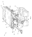
Fig. 1 is a perspective side view of a surgical support system according to one illustrative embodiment of the current disclosure showing a surgical table and a hip distractor assembly; -
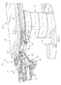
Fig. 2 is a perspective side view of the hip distractor assembly ofFig. 1 showing the table extension coupled to the surgical table by a bracket; -
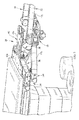
Fig. 3 is a perspective side view of the hip distractor assembly ofFig. 1 showing the table extension and non-operative leg holder assembly coupled to the surgical table by the same bracket; -
Fig. 4 is a perspective top view of the table extension ofFig. 1 ; -
Fig. 5 is a perspective bottom view of the table extension ofFig. 1 ; -
Fig. 6 is a side view of the table extension ofFig. 1 ; -
Fig. 7 is a bottom view of the table extension ofFig. 1 ; -
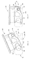
Fig. 8 is a perspective side view of the bracket ofFig. 2 showing the insert engaging the bracket; -
Fig. 9 is a perspective top view of the bracket ofFig. 2 ; -
Fig. 10 is a perspective side view of the bracket ofFig. 2 showing the rail adapter portion; -
Fig. 11 is a perspective side view of the bracket ofFig. 3 showing the trigger; -
Fig. 12 is a perspective side view of the non-operative leg holder ofFig 1 showing the coupling portion coupled to the bracket; -
Fig. 13 is a side view of the connector for the operational leg holder assembly ofFig. 1 showing the connector; -
Fig. 14 is a side view of the connector ofFig. 13 being inserted in the slot on the table extension; -
Fig. 15 is a side view of the connector ofFig. 13 secured in the slot; and -
Fig. 16 is a side view of the connector ofFig. 13 not secured in the slot. - A
surgical support system 10 according to one contemplated embodiment is shown inFigs.1-16 . Thesystem 10 includes a surgicalperson support apparatus 12 and ahip distractor assembly 14 orsurgical support device 14 coupled to theperson support apparatus 12. In one contemplated embodiment, the person supportapparatus 12 is a surgical table 12 or operating room table 12 and includes abase 16, alift system 18, and anupper frame 20 movably supported above the base. Theupper frame 20 includes ahead section 22, aseat section 24 andattachment rails 26. In some contemplated embodiments theupper frame 20 includes a foot section (not shown) that can be removed or moved out of the way when surgical equipment or accessories, such as, thehip distractor assembly 14 or a surgical spine system like the Allen® Spine System sold by Allen Medical Systems, are attached to the surgical table 12 as shown inFig. 1 . Therails 26 extend along the sides of thesections - The
hip distractor assembly 14 includes atable extension 28, an operativeleg holder assembly 30 orleg support 30, a non-operativeleg holder assembly 32 orleg support 32, andmounting brackets 34 orconnector 34 as shown inFig. 3 . Thetable extension 28 and the non-operativeleg holder assembly 32 are configured to be coupled to therails 26 via thebrackets 34, and the operativeleg holder assembly 30 is configured to be coupled to thetable extension 28. - The
table extension 28 comprises atable coupling assembly 36, a connectingframe 38, a Y-shapedsupport frame assembly 40, and aplatform 42 as shown inFigs. 1-3 . The connectingframe 38 is coupled between thetable coupling assembly 36 and thesupport frame assembly 40 and includes an upper portion that cooperates with thetable coupling assembly 36 to support theplatform 42, and a lower portion that supports thesupport frame assembly 40 vertically below a portion of theplatform 42. Theplatform 42 is substantially planar and includes abase portion 43a coupled to thetable coupling assembly 36, and ahip support portion 43b extending from thebase portion 43a that is coupled to the connectingframe 38. In some contemplated embodiments, a support surface (not shown), such as, a foam pad, can be positioned on theplatform 42. The hip support portion 43 is shaped to support a person's non-operative hip while allowing the person's operative hip to hang off theplatform 42 unsupported. - The
table coupling assembly 36 includes a lengthadjustable beam 44 and coupling assemblies 46 attached to the ends of thebeam 44 as shown inFigs. 4-8 . The length adjustingbeam 44 includes a telescoping arrangement that is configured to be adjusted to match the width of theperson support apparatus 12, and locked in place withlocking screw 45 when a desired width has been reached. The coupling assemblies 46 include ahandle 48, afork plate 50, and aninsert 52. Thehandle 48 is coupled to thefork plate 50 and thefork plate 50 is coupled to thebeam 44 by theinsert 52. Thefork plate 50 includes aguide slot 54 that is configured to engage thebracket 34 to help position thetable extension 28 and maintain the engagement of thetable extension 28 and thebracket 34. Thefork plate 50 is shorter in length along the upper portion of theguide slot 54 to provide a lead in section that make it easier for a user to engage thebracket 34 with theguide slot 54. Theinsert 52 includes abase portion 56 and anextension 58 that extends from thebase portion 56. Theextension 58 includes agroove 60 and acurved portion 62 that are configured to engage thebracket 34 to help position thetable extension 28 and maintain the engagement of thetable extension 28 and thebracket 34. - The
support frame assembly 40 is generally Y-shaped and is configured to support the operativeleg holder assembly 30. Thesupport frame assembly 40 includes aframe 64 with abase 66 andangled arms 68,perineal post cones 70, ahandle 72, connectingportion 74, and amounting assembly 76 orconnector enabling assembly 76 as shown inFigs. 4-7 . In some contemplated embodiments, thesupport frame 40 supports a perineal post (not shown) that extends up through the opening 43c in theplatform 42 on aperineal post cone 70. Thebase 66 is coupled to the connectingframe 38 and theangled arms 68 extend from thebase 66 to form Y shape. Thehandle 72 is coupled between theangled arms 68 and is configured to be used to transport thetable extension 28. Theperineal post cones 70 are coupled to theangled arms 68 and are aligned with theopenings 43c in thepanel 42. The connectingportions 74 are located at the ends of theangled arms 68 and include anelongated slot 78 formed in theangled arm 68, alocking knob 80 positioned in alocking bore 82, and a mount bore 84 that a portion of themounting assembly 76 moves within. In some contemplated embodiments aplug 86 can be inserted into an end of themounting bore 84. Theelongated slot 78 includesrounded opening edges 87a that helps guide the leg holder assembly into theslot 78, and an opening 87b in the bottom of the slot to help position and maintain the leg holder assembly in theslot 78. - The
mounting assembly 76 extends between theangled arms 68 and is configured to allow a user to select which connectingportion 74 they would like to attach the operativeleg holder assembly 30 to. Themounting assembly 76 includes ashaft 88 and ahandle 90 coupled to theshaft 88 as shown inFigs. 4-7 . Theshaft 88 is sized such that theshaft 88 can only extend across theslot 78 of one of the connectingportions 74 so that only one operativeleg holder assembly 30 can be supported by thetable extension 28 at a time. Thehandle 90 is configured to move theshaft 88 and allow a user to select the connectingportion 74 they would like to attach the operativeleg holder assembly 30 to. Theshaft 88 is positioned within themounting bores 84 and extends between theslots 78. In some contemplated embodiments, theshaft 88 is sized so that theshaft 88 does not extend across the slot of either connectingportion 74 when thehandle 90 is in a neutral position. In some contemplated embodiments, theshaft 88 is sized to extend across bothslots 78 simultaneously, or two smaller shafts (not shown) are used and are positioned such that they each extend across one of theslots 78 so that more than one leg holder assembly can be supported by thetable extension 28. In some contemplated embodiments, an indicator or a graphic (not shown) is used to indicate which way to move thehandle 90 based on the patient's legs to be supported. In some contemplated embodiments, the indicator or graphic is used to indicate which leg should be supported based on the current configuration of the device (i.e., left, right, none). In another contemplated embodiment, theangled arms 68 include a pair of go/no-go openings 92 that show a portion of themounting shaft 88 that may be colored red or green to indicate which connectingportion 74 the user can connect a leg holder assembly to. - The
coupling bracket 34 includes a first side S1, a second side S2, a third side S3 extending between the first side S1 and the second side S2, arail adapter portion 136, aguide pin 138, a lockingknob 140, atable extension support 142, and a legholder support portion 144 as shown inFigs. 8-12 . Therail adapter portion 136 extends from the first side S1 and is configured to engage therail 26 and movably retain thebracket 34 on therail 26. Therail adapter portion 136 includes anupper guide 146 that engages a portion of a top edge of therail 26 and alower guide 148 that engages a portion of the bottom edge of therail 26. Theguide 138 extends from the second side S2 and is configured to be engaged bytable extension 28 and help align and support thetable extension 28 when thetable extension 26 is coupled to thebracket 34. - The locking
knob 140 extends from the second side S2 that is adjacent to theguide pin 138 and positioned in alocking opening 145 extending though thebracket 34 as shown inFigs. 8-12 . The lockingknob 140 is configured to cooperate with theguide 146 andlower guide 148 to selectively engage therail 26 to prevent thebracket 34 from moving with respect to therail 26. In some contemplated embodiments the lockingknob 140 is captured in thebracket 34 so that the lockingknob 140 is prevented from falling off when theknob 140 is loosened to allow thebracket 34 to be removed from therail 26. - The
table extension support 142 includes aninsert engaging surface 150 with aprotrusion 152 and atrigger 154. Theinsert engaging surface 150 is configured to be engaged by theextension 58 and theprotrusion 152 is configured to engage theslot 60 in theinsert 52 as shown inFig. 8 . Thetrigger 154 is configured to selectively engage thecurved portion 62 of theextension 58 to maintain theinsert 52 from being removed from thetable extension support 142 as shown inFigs. 8 and12 . In some contemplated embodiments, thetrigger 154 is only included on one of thebrackets 34 coupling thetable extension 28 to the surgical table 12. Thetrigger 154 is rotatably coupled within atrigger recess 156 that is recessed from the third surface S3 and includes anangled surface 158 and astop arm 160. When thetable extension 28 is being coupled to thebracket 34 and theextension 58 is moved into engagement with theinsert engaging surface 150, thecurved portion 62 of theinsert 54 engages anangled side 158 of thetrigger 154 and causes thetrigger 154 to rotate from a first position, where thestop arm 160 engages the back of thetrigger recess 156, to a second position, where thestop arm 160 is away from the back of thetrigger recess 156. When theextension 58 engages theinsert engaging surface 150, gravity (or a spring mechanism) causes thetrigger 154 to rotate back to the first position to prevent thetable extension 28 from accidentally or unintentionally being removed from thebracket 34. Thetrigger 154 must be manually moved from the first position to the second position by a user before thetable extension 28 can be removed from thebracket 34. To do so, a user can use their thumb to pull thestop arm 160 away from the back of thetrigger recess 156 and remove theinsert 54 from thetable extension support 142. - The leg
holder support portion 144 includes a hook shapedrecess 162, a lockingknob opening 164, and an anti-rotation pin opening 166 as shown inFigs. 8-12 . The hook shapedrecess 162 is positioned generally vertically below the tableextension support portion 142 and is shaped to help guide thecoupling pin 176 of the non-operativeleg coupling assembly 168 toward the base of the hook shapedrecess 162. The anti-rotation pin opening 166 is configured to receive an anti-rotation pin (not shown) that engages the recessedgroove 180 in thecoupling assembly 168 and prevents theleg holder assembly 32 from rotating when thecoupling pin 60 is located at the base of the hook shapedrecess 54. By preventing rotation of the non-operativeleg holder assembly 32, a user can attach theleg holder assembly 32 to thebracket 34 and secure theleg holder assembly 32 with the legholder locking knob 178 without having to support theleg holder assembly 32 themselves to maintain alignment of the lockingknob opening 164 and the legholder locking knob 178. - The non-operative
leg holder assembly 32 includes a non-operativeleg coupling assembly 168, afirst spar 170 oradapter 170, and asecond spar 172 as shown inFigs. 1-3 and12 . Thecoupling assembly 168 is generallyU-shaped bracket 174 with thecoupling pin 176 extending between the sides of thebracket 174, and the legholder locking knob 178 engaging alocking opening 179 passing through one side of thebracket 174. In some contemplated embodiments, thebracket 174 includes a recessedgroove 180 configured to engage the anti-rotation pin extending from thebracket 34. Thecoupling assembly 168 is attached to thefirst spar 170 and thefirst spar 170 is rotatably attached to thesecond spar 172. Thesecond spar 172 is configured to support a foot holding device (not shown). In one contemplated embodiment, thefirst spar 170 is pivotably and removably coupled to thesecond spar 172 at a joint. In another contemplated embodiment, the user couples thefirst spar 170 to thesecond spar 172 in a first orientation when theassembly 32 is connected to one side of theperson support apparatus 12, i.e., the left side, and disconnects, flips over, and reconnects thefirst spar 170 to thesecond spar 172 in a second orientation when the user desires to connect theassembly 32 to the other side, i.e., the right side, of theperson support apparatus 12. - The operative
leg holder assembly 30 includes aspar 182 and aconnector 184 coupled to the end of thespar 182 as shown inFigs. 1-2 and13-16 . Theconnector 184 includes ahook end 186, a lockingbore 188, and a mountingend 190 opposite thehook end 186. Thehook end 186 is configured to engage the mountingshaft 88 when the operativeleg holder assembly 30 is attached to the connectingportion 74 of thetable extension 28. Thehook end 186 includes anangled end 192 that helps guide the mountingshaft 88 toward the base of thehook 186. Theconnector 184 is shaped such that when thehook end 186 engages the mountingshaft 88, a portion of theconnector 184 extends through theopening 87b in the bottom of theslot 78 and the mountingend 190 engages the mountingportion 194 of theslot 78 to help position theconnector 184 in theslot 78 such that the locking bore 188 and the locking bore 82 are substantially aligned so the lockingknob 80 can be tightened to secure theleg holder assembly 30 to thetable extension 28 as shown inFig 15 . In addition to help position theconnector 184 in theslot 78, the mountingend 190 helps maintain the engagement of thehook end 186 and the mountingshaft 88 so that theleg holder assembly 30 is supported by thetable extension 28 and the user does not need to support theleg holder assembly 30 while attempting to secure it in place with the lockingknob 80. If a user attempted to mount theleg holder assembly 30 to a connectingportion 74 that the mountingshaft 88 did not extend across, theleg holder assembly 30 would not be fully supported by thetable extension 28 because theconnector 184 would be allowed to rotate in theslot 78 as shown inFig. 16 , due to the rotational moment caused by the weight of theleg holder assembly 30. - Many other embodiments of the present disclosure are also envisioned. For example, a surgical support system comprises a surgical table; a first leg support assembly coupled to the surgical table; a second leg support assembly; and a surgical table extension coupled to the surgical table and including a first connector and a second connector and a connector enabling assembly configured to selectively enable the second leg support assembly to be coupled to one of the first connector and the second connector.
- In another example, a surgical support system comprises a surgical table; a leg support assembly including a leg support connector with a hook shaped portion; and a surgical table extension coupled to the surgical table and including a first connector defining a first slot with a first shaft extending across the first slot and a second connector defining a second slot with a second shaft extending across the second slot, wherein the hook shaped portion is configured to engage one of the first shaft and the second shaft when the leg support connector is inserted into one of the first slot and the second slot, respectively.
- In another example, a bracket for coupling at least one surgical table accessory to a surgical table comprises a rail coupling portion; a first accessory retaining portion; and a second accessory retaining portion positioned vertically below the first retaining portion.
- In another example a surgical table extension comprises a surgical table frame coupled to a surgical table by a connecting assembly; a first accessory connector; a second accessory connector; and an accessory connector enabling assembly configured to be moved between a first position and a second position, wherein the first accessory connector is configured to receive and retain an accessory when the accessory connector enabling assembly is in the first position and the second accessory connector is configured to receive and retain an accessory when the accessory connector enabling assembly is in the second position.
- It should be understood that only selected embodiments have been shown and described and while those embodiments of the disclosure have been illustrated and described in detail in the drawings and foregoing description, the same are to be considered as illustrative and not intended to be exhaustive. Additional alternatives, modifications and variations may be apparent to those skilled in the art. Also, while multiple inventive aspects and principles may have been presented, they need not be utilized in combination, and various combinations of inventive aspects and principles are possible in light of the various embodiments provided above.
- Embodiments of the invention can be described with reference to the following numbered clauses, with preferred features laid out in the dependent clauses:
- 1. A surgical support device, comprising:
- a first support accessory connector configured to be selectively enabled;
- a second support accessory connector configured to be selectively enabled; and
- a connector enabling assembly configured to selectively enable one of the first support accessory connector and the second support accessory connector to removably couple with a support accessory.
- 2. The surgical support device of clause 1, wherein the support accessory is configured to support a person's limb.
- 3. The surgical support device of clause 1 further comprising:
- a coupling portion configured to be coupled to a person support apparatus; and
- a support surface configured to support a portion of a person supported on the person support apparatus.
- 4. The surgical support device of clause 1, wherein the connector enabling assembly is in a first position when the first support accessory connector is enabled and a second position when the second support accessory connector is enabled.
- 5. The surgical support device of clause 4, wherein the connector enabling assembly is in a third position when both of the first support accessory connector and the second support accessory connector are disabled.
- 6. The surgical support device of clause 1, wherein the first support accessory connector includes a first slot, the second support accessory connector includes a second slot, and the connector enabling assembly includes a shaft configured to extend at least partially across one of the first slot and the second slot to enable the one of the first support accessory connector and the second support accessory connector, respectively.
- 7. The surgical support device of clause 6, wherein the connector enabling assembly is in a first position when the shaft extends across the first slot and in a second position when the shaft extends across the second slot and in a third position when the shaft does not extend across either of the first slot and the second slot.
- 8. The surgical support device of clause 1 further comprising indicators configured to indicate the enablement status of at least one of the first support accessory connector and the second support accessory connector.
- 9. The surgical support device of clause 7, wherein the connector enabling assembly includes a shaft, a portion of the shaft is colored to indicate the enablement status.
- 10. The surgical support device of clause 1 further comprising an indicator configured to indicate which of the first support accessory connector and the second support accessory connector should be enabled to support a particular limb of a person supported on the surgical person support apparatus.
- 11. The surgical support device of clause 1, wherein the support accessory cannot be coupled to either of the first support accessory connector and the second support accessory connector when the first support accessory connector and the second support accessory connector are disabled.
- 12. The surgical support device of clause 1, wherein the first connector includes a first slot and a first slot guide, and the second connector includes a second slot and a second slot guide, the first slot guide and the second slot guide are configured to guide a connecting portion of the support accessory into the respective one of the first slot and the second slot.
- 13. A surgical table extension, comprising:
- a frame including a surgical table connecting portion, a first connector, and a second connector; and
- a connector enabler movably coupled to the frame and configured to selectively enable one of the first connector and the second connector to be removably coupled with a support device.
- 14. The surgical table extension of clause 13, wherein the support device is configured to support a person's limb.
- 15. The surgical table extension of clause 13, wherein the connector enabler is in a first position when the first connector is enabled, a second position when the second connector is enabled, and in a third position when both of the first connector and the second connector are disabled.
- 16. The surgical table extension of clause 13, wherein the first support accessory connector includes a first slot, the second support accessory connector includes a second slot, the frame includes a bore extending between the first slot and the second slot, and the connector enabler includes a shaft positioned within the bore, the shaft extending at least partially across one of the first slot and the second slot to enable the one of the first connector and the second connector, respectively.
- 17. The surgical table extension of clause 13 further comprising an indicator configured to indicate the enablement status of at least one of the first connector and the second connector.
- 18. The surgical table extension of clause 17, wherein the frame includes a bore extending between the first connector and the second connector, and the connector enabler includes a shaft positioned within the bore, a portion of the shaft being colored to indicate the enablement status of at least one of the first connector and the second connector.
- 19. The surgical table extension of clause 13 further comprising an indicator configured to indicate which of the first connector and the second connector should be enabled to support a particular limb of a person.
- 20. The surgical table extension of clause 13, wherein the first connector and the second connector include a slot including a mount extending across a first portion of the slot and an opening that a portion of the connector enabler is configured to selectively extend through to enable the one of the first connector and the second connector, the mounting portion being configured to support the weight of the support device when a connecting portion of the support device engages the portion of the connector enabler extending into the slot.
- 21. The surgical table extension of
clause 20, wherein the frame includes a securing element configured to secure the support device to the enabled one of the first connector and the second connector when the connecting portion of the support device engages the portion of the connector enabler extending into the slot. - 22. The surgical table extension of
clause 20, wherein the mount and the portion of the connector enabler cooperate to prevent the connecting portion of the support device from rotating out of the slot. - 23. The surgical table extension of
clause 22, wherein the connecting portion includes a mount engaging portion configured to engage the mount and a hook configured to engage the portion of the connector enabler. - 24. A connector configured to couple a table extension and a limb support assembly to a surgical table, comprising:
- a first connecting portion configured to be removably coupled to the surgical table;
- a second connecting portion configured to be removably coupled to a portion of the surgical table extension; and
- a third connecting portion configured to be removably coupled to a portion of the limb support assembly, wherein the limb support and the surgical table extension are simultaneously couplable to the third connecting portion and the second connecting portion, respectively.
- 25. The connector of
clause 24, wherein the second connecting portion includes a latch configured to selectively maintain the engagement of the portion of the surgical table extension and the second connecting portion. - 26. The connector of clause 25, wherein the latch is moved from a first position to a second position by the surgical table extension when the portion of the surgical table extension partially engages the first connecting portion, and moves from the second position to the first position when the portion of the surgical table extension fully engages the first connecting portion.
- 27. The connector of
clause 26, wherein the lock is manually moved from the second position to the first position to disengage the first accessory from the bracket. - 28. The connector of
clause 24, wherein the second connecting portion includes a locator configured to cooperate with a corresponding locator on the surgical table extension to locate the portion of the surgical table extension on the second connecting portion. - 29. The connector of
clause 24, wherein the second accessory retaining portion includes a horizontally extending slot and an anti-rotation member, the anti-rotation member is configured to engage a portion of an accessory to limit rotation of the accessory with respect to the connector when a portion of the accessory is positioned within the slot. - 30. The connector of clause 29, wherein the anti-rotation member and the slot are configured to align a retaining element on the second accessory retaining portion with a retaining element on the accessory when the accessory engages the horizontally extending slot and the anti-rotation member.
- 31. The connector of
clause 24, wherein the first connecting portion is configured to engage a rail on the surgical table. - 32. The connector of
clause 24, wherein the second portion includes a hook-shaped portion. - 33. A support system, comprising:
- a limb support;
- a surgical table extension; and
- a connector including a first device coupling portion and a second device coupling portion, the connector being configured to simultaneously couple the limb support and the surgical table extension to a surgical person support apparatus.
- 34. The connector of clause 33, wherein the second device coupling portion includes a latch configured to selectively secure the surgical table extension to the connector.
- 35. The connector of clause 33, wherein the second device coupling portion includes a locator configured to cooperate with a corresponding locator on the surgical table extension to locate the surgical table extension on the second device coupling portion.
- 36. The connector of clause 33, wherein the second accessory retaining portion includes a hook shaped receptacle and an anti-rotation pin, the anti-rotation pin is configured to engage a portion of the limb support to prevent the limb support from rotating when a portion of the limb support engages the hook shaped receptacle.
- 37. The connector of clause 33, wherein the first connecting portion is configured to engage a rail on the surgical table.
- 38. A support system, comprising:
- a first limb support configured to be coupled to a surgical table;
- a surgical table extension configured to be coupled to the surgical table; and
- a second limb support configured to be coupled to the surgical table extension, wherein the first limb support and the second limb support are not simultaneously couplable to the surgical table extension.
- 39. The support system of
clause 38, wherein the surgical table extension includes a first connector, a second connector, and a connector enabler configured to enable one of the first connector and the second connector, the second limb support being coupled to the enabled one of the first connector and the second connector. - 40. The support system of clause 39, wherein the second limb support includes a connecting element configured to engage the enabled one of the first connector and the second connector, the weight of the second limb support generates a rotational moment about an axis which biases the connecting element to engage the enabled one of the first connector and the second connector when the connecting element is in a first position.
- 41. The support system of
clause 40, wherein the connecting element includes an elongated slot and a mounting portion, the elongated slot being configured to engage a portion of the connector enabler and the mounting portion being configured to engage a mounting portion of the enabled one of the first connector and the second connector in the first position. - 42. The support system of
clause 38 further comprising a connector configured to couple both the first limb support and the surgical table extension to the surgical table. - 43. The support system of
clause 38, wherein the first limb support includes a support member and an adapter pivotably coupled to the support member in a first orientation when the first limb support is coupled to a first side of the surgical table and pivotably coupled to the support member in a second orientation when the first limb support is coupled to a second side of the surgical table, the adapter being rotated about an axis extending along the length of the adapter when the adapter is moved between the first orientation and the second orientation. - 44. The support system of clause 41, wherein the adapter is de-coupled from the support member, rotated about the axis, and re-coupled to the support member when the first limb support is moved from the first side of the surgical table to the second side of the surgical table.
- 45. A limb support assembly, comprising:
- a limb support; and
- an adapter pivotably and removably coupled to the limb support, the adapter including a coupling assembly configured to couple the limb support to a surgical table, the adapter being coupled to the support member in a first orientation when the limb support assembly is connected to a first side of the surgical table and coupled to the limb support in a second orientation when the limb support assembly is connected to a second side of the surgical table, wherein the adapter is rotated about an axis extending along the length of the adapter when the adapter is moved between the first orientation and the second orientation.
- 46. The limb support assembly of
clause 45, wherein the adapter is de-coupled from the limb support, rotated about the axis, and re-coupled to the limb support when the limb support assembly is moved from the first side of the surgical table to the second side of the surgical table. - 47. The limb support assembly of
clause 45, wherein the coupling assembly includes a pin configured to engage a slot on a surgical table connector and an anti-rotation groove configured to engage an anti-rotation element on the surgical table connector, wherein the weight of the limb support assembly maintains the engagement of the pin with the slot and the anti-rotation groove with the anti-rotation element. - 48. A limb support assembly, comprising:
- a limb support; and
- a support connector coupled to the limb support and configured to engage an accessory connector on a surgical support device, wherein the weight of the limb support assembly generates a rotational moment about an axis that causes the support connector to be biased to engage the accessory connector in a first position.
- 49. The limb support assembly of
clause 48, wherein the accessory connector is selectively enabled by a connector enabling assembly, wherein the support connector is configured to be coupled to the accessory connector when the accessory connector is enabled. - 50. The limb support assembly of
clause 48, wherein the support connector includes a hook portion. - 51. The limb support assembly of
clause 48, wherein the support connector is simultaneously rotated and translated from a disengaged position to the first position where the support connector engages the accessory connector. - 52. A limb support system, comprising:
- a limb support; and
- a means for coupling the limb support to a surgical person support apparatus such that the weight of the limb support generates a rotational moment that causes the means for connecting the limb support to be biased toward engagement with the surgical person support apparatus.
- 53. The limb support assembly of
clause 52, wherein the person support apparatus includes an accessory connector configured to be selectively enabled by a connector enabling assembly, wherein the means for coupling the limb support to a surgical person support apparatus is configured to be coupled to the accessory connector when the accessory connector is enabled. - 54. The limb support assembly of clause 53, wherein the means for coupling the limb support to a surgical person support apparatus is simultaneously rotated and translated from a disengaged position to the first position where the support connector engages the accessory connector.
- 55. The limb support assembly of
clause 48, wherein the means for coupling the limb support to a surgical person support apparatus includes a hook portion. - 56. A support system, comprising:
- a surgical person support accessory including a device connector;
- a limb support; and
- a limb support connector configured to couple the limb support to the surgical person support apparatus, wherein the limb support connector is configured to engage the device connector such that the weight of the limb support maintains the engagement of the limb support connector and the connector.
- 57. The support system of
clause 56, wherein the device connector is selectively enabled by a connector enabling assembly, wherein the limb support connector is configured to be coupled to the device connector when the device connector is enabled. - 58. The support system of clause 57, wherein the device connector includes a slot and the connector enabling assembly includes a shaft that is configured to be selectively extend across the slot to enable the connector, wherein the limb support connector is configured to engage the shaft in an engaged position.
- 59. The support system of
clause 56, wherein the limb support connector includes a hook portion. - 60. The support system of
clause 56, wherein the limb support connector is simultaneously rotated and translated from a disengaged position to a first position where the limb support connector engages the device connector.
Claims (9)
- A connector configured to couple a table extension and a limb support assembly to a surgical table, comprising:a first connecting portion configured to be removably coupled to the surgical table;a second connecting portion configured to be removably coupled to a portion of the surgical table extension; anda third connecting portion configured to be removably coupled to a portion of the limb support assembly, wherein the limb support and the surgical table extension are simultaneously couplable to the third connecting portion and the second connecting portion, respectively.
- The connector of claim 1, wherein the second connecting portion includes a latch configured to selectively maintain the engagement of the portion of the surgical table extension and the second connecting portion.
- The connector of claim 2, wherein the latch is moved from a first position to a second position by the surgical table extension when the portion of the surgical table extension partially engages the first connecting portion, and moves from the second position to the first position when the portion of the surgical table extension fully engages the first connecting portion.
- The connector of claim 3, wherein the lock is manually moved from the second position to the first position to disengage the first accessory from the bracket.
- The connector of claim 1, wherein the second connecting portion includes a locator configured to cooperate with a corresponding locator on the surgical table extension to locate the portion of the surgical table extension on the second connecting portion.
- The connector of claim 1, wherein the second accessory retaining portion includes a horizontally extending slot and an anti-rotation member, the anti-rotation member is configured to engage a portion of an accessory to limit rotation of the accessory with respect to the connector when a portion of the accessory is positioned within the slot.
- The connector of claim 6, wherein the anti-rotation member and the slot are configured to align a retaining element on the second accessory retaining portion with a retaining element on the accessory when the accessory engages the horizontally extending slot and the anti-rotation member.
- The connector of claim 1, wherein the first connecting portion is configured to engage a rail on the surgical table.
- The connector of claim 1, wherein the second portion includes a hook-shaped portion.
Priority Applications (1)
| Application Number | Priority Date | Filing Date | Title |
|---|---|---|---|
| EP17151791.5A EP3175833A1 (en) | 2012-09-07 | 2013-09-05 | Surgical support system |
Applications Claiming Priority (3)
| Application Number | Priority Date | Filing Date | Title |
|---|---|---|---|
| US201261698547P | 2012-09-07 | 2012-09-07 | |
| US13/799,251 US9730851B2 (en) | 2012-09-07 | 2013-03-13 | Surgical support system |
| EP13183197.6A EP2705822B1 (en) | 2012-09-07 | 2013-09-05 | Surgical support system |
Related Parent Applications (1)
| Application Number | Title | Priority Date | Filing Date |
|---|---|---|---|
| EP13183197.6A Division EP2705822B1 (en) | 2012-09-07 | 2013-09-05 | Surgical support system |
Related Child Applications (1)
| Application Number | Title | Priority Date | Filing Date |
|---|---|---|---|
| EP17151791.5A Division EP3175833A1 (en) | 2012-09-07 | 2013-09-05 | Surgical support system |
Publications (2)
| Publication Number | Publication Date |
|---|---|
| EP2932952A1 true EP2932952A1 (en) | 2015-10-21 |
| EP2932952B1 EP2932952B1 (en) | 2017-01-25 |
Family
ID=49165530
Family Applications (3)
| Application Number | Title | Priority Date | Filing Date |
|---|---|---|---|
| EP13183197.6A Active EP2705822B1 (en) | 2012-09-07 | 2013-09-05 | Surgical support system |
| EP17151791.5A Withdrawn EP3175833A1 (en) | 2012-09-07 | 2013-09-05 | Surgical support system |
| EP15169611.9A Active EP2932952B1 (en) | 2012-09-07 | 2013-09-05 | Surgical support system |
Family Applications Before (2)
| Application Number | Title | Priority Date | Filing Date |
|---|---|---|---|
| EP13183197.6A Active EP2705822B1 (en) | 2012-09-07 | 2013-09-05 | Surgical support system |
| EP17151791.5A Withdrawn EP3175833A1 (en) | 2012-09-07 | 2013-09-05 | Surgical support system |
Country Status (2)
| Country | Link |
|---|---|
| US (2) | US9730851B2 (en) |
| EP (3) | EP2705822B1 (en) |
Families Citing this family (14)
| Publication number | Priority date | Publication date | Assignee | Title |
|---|---|---|---|---|
| US9901503B2 (en) | 2008-03-13 | 2018-02-27 | Optimedica Corporation | Mobile patient bed |
| US9730851B2 (en) | 2012-09-07 | 2017-08-15 | Allen Medical Systems, Inc. | Surgical support system |
| EP2873405B1 (en) * | 2013-11-18 | 2016-05-18 | Schaerer Medical Management AG | Modular operating table |
| CA2936677A1 (en) * | 2014-01-13 | 2015-07-16 | Ferno-Washington, Inc. | Accessory clamp for emergency cots |
| DE102016216996A1 (en) * | 2016-09-07 | 2018-03-08 | Trumpf Medizin Systeme Gmbh + Co. Kg | Connection device and method for unlocking the connection device |
| CN106726311B (en) * | 2017-02-17 | 2018-10-26 | 广州中医药大学第一附属医院 | An angle-adjustable hip herringbone plaster orthopedic bed |
| US11234885B2 (en) * | 2018-02-20 | 2022-02-01 | Allen Medical Systems, Inc. | Adjustable lithotomy positioning apparatus with a limb rest |
| BE1026472B1 (en) * | 2018-07-16 | 2020-02-10 | Orfit Ind | First trunk element of a connecting assembly for releasably connecting an extension panel to a patient support panel mounted on a pedestal |
| CO2019000131A1 (en) * | 2019-01-09 | 2019-02-19 | Winkler Carlos Alfonso Prada | Tractor and lower limb positioner for osteosynthesis surgery and hip arthroscopy |
| US11730560B2 (en) | 2019-07-12 | 2023-08-22 | Stuckenbrock Medizintechnik Gmbh | Fast-action clamping device with locking mechanism, and surgical device |
| US10729577B1 (en) * | 2019-09-11 | 2020-08-04 | King Saud University | Hip spica cast application device |
| CN211356501U (en) * | 2019-11-05 | 2020-08-28 | 通快医疗系统两合公司 | Supporting plate connecting device of operating table extension unit and operating table |
| US11890118B2 (en) | 2021-03-24 | 2024-02-06 | Stryker Corporation | Patient support apparatus with support assembly for medical device |
| CN113855452A (en) * | 2021-10-22 | 2021-12-31 | 西安大兴医院 | Endocrinology department uses multi-functional inspection desk |
Citations (3)
| Publication number | Priority date | Publication date | Assignee | Title |
|---|---|---|---|---|
| US5056535A (en) * | 1990-01-22 | 1991-10-15 | Leonard Medical | Varus and valgus leg manipulator |
| US20090307845A1 (en) * | 2008-06-13 | 2009-12-17 | Rao Sudhir B | Shoulder surgery attachment for a surgical table |
| US20110099720A1 (en) * | 2009-09-30 | 2011-05-05 | Maquet Gmbh & Co. Kg | Adapter for connecting at least one accessory device to an operating table |
Family Cites Families (185)
| Publication number | Priority date | Publication date | Assignee | Title |
|---|---|---|---|---|
| US1160451A (en) | 1914-04-06 | 1915-11-16 | Charles H Sanford | Combined fracture and orthopedic operating-table. |
| US1501120A (en) | 1921-03-17 | 1924-07-15 | Eduard H Karrer | Traction apparatus |
| US3509876A (en) | 1966-10-18 | 1970-05-05 | Stierlen Werke Ag | Apparatus for the treatment of bone fractures |
| BR6899660D0 (en) | 1968-06-06 | 1973-03-13 | A Staib | IMPROVEMENTS IN TRACTION DEVICES FOR ORTHOPEDIC TABLES |
| US3745996A (en) | 1971-02-19 | 1973-07-17 | Berivon Co | Apparatus for the reduction of bone fractures |
| US3982742A (en) | 1975-11-17 | 1976-09-28 | Ford John L | Medical stirrups |
| GB1596036A (en) | 1977-04-01 | 1981-08-19 | Nat Res Dev | Surgical apparatus |
| US4180062A (en) * | 1978-04-10 | 1979-12-25 | James Alberti | Portable childbirth chair with electronic monitoring apparatus |
| US4185813A (en) | 1978-05-17 | 1980-01-29 | Spann Donald C | Surgical body positioner |
| US4471952A (en) | 1979-04-26 | 1984-09-18 | Span-America Medical Systems, Inc. | Surgical body positioner and disposable topper |
| US4252306A (en) | 1979-09-13 | 1981-02-24 | Lanny L. Johnson | Device for clamping body parts |
| US4766892A (en) | 1980-07-25 | 1988-08-30 | Gary Kreitman | Limb restraint |
| US4373709A (en) | 1980-09-24 | 1983-02-15 | Whitt Everett D | Surgical limb holder |
| US4407277A (en) | 1980-10-27 | 1983-10-04 | Ellison Arthur E | Surgical apparatus |
| US4418900A (en) | 1981-03-03 | 1983-12-06 | Ricke Theodore D | Corpse positioning system |
| US4428571A (en) | 1981-05-15 | 1984-01-31 | Sugarman Edward D | Limb positioning device |
| US4579324A (en) | 1981-05-27 | 1986-04-01 | Mcconnell Bernard E | Universal extremity positioner |
| US4367869A (en) | 1981-09-10 | 1983-01-11 | Dailey Thomas H | Stirrup attachment for surgical table |
| US4872656A (en) | 1981-12-21 | 1989-10-10 | American Sterilizer Company | Orthopedic table with movable upper body and sacrum supports |
| US4443005A (en) | 1982-09-09 | 1984-04-17 | Edward D. Sugarman | Foot support device |
| US4526355A (en) | 1982-09-29 | 1985-07-02 | Moore Robert R | Arthroscopic leg holder |
| US4545573A (en) | 1983-03-03 | 1985-10-08 | Saginaw Automation & Machine, Inc. | Surgical leg clamp |
| US4732145A (en) | 1984-09-14 | 1988-03-22 | Latham Philip B | Restraining device for spinal taps |
| US5015251A (en) | 1984-11-30 | 1991-05-14 | Alimed, Inc. | Medical fastener strap |
| US4620698A (en) | 1985-03-04 | 1986-11-04 | Professional Medical Products, Inc. | Orthopedic support device |
| US4782827A (en) | 1985-12-05 | 1988-11-08 | Bernard Paratte | Orthopedic apparatus |
| FR2596637B1 (en) | 1986-04-03 | 1988-07-15 | Marzet Aubry | TRACTION DEVICE FOR OPERATING TABLES AND ORTHOPEDIC SURGERY APPARATUS |
| US4681309A (en) | 1986-05-12 | 1987-07-21 | Paula Lechner | Surgical prep block and surgical assist block |
| US4827496A (en) | 1986-06-23 | 1989-05-02 | M. C. Johnson Co., Inc. | Leg and ankle holder for assisting medical and radiological professionals in X-ray examination and filming of the ankle and foot structure |
| FR2621245B1 (en) | 1987-10-05 | 1997-10-24 | Tasserit Ets | ORTHOPEDIC OPERATING TABLE FOR MEMBERS AND PARTICULARLY FOR LOWER MEMBERS |
| US4809687A (en) | 1987-12-30 | 1989-03-07 | Edgewater Medical Systems | Medical stirrup |
| US4964400A (en) | 1988-04-19 | 1990-10-23 | Lincoln Mills, Inc. | Surgical limb supporting apparatus with tension measuring device |
| US5001739A (en) | 1988-06-06 | 1991-03-19 | Fischer William B | Contoured surgical table |
| US4886258A (en) | 1988-08-24 | 1989-12-12 | Scott James W | Well leg operative support |
| US4913413A (en) | 1989-06-09 | 1990-04-03 | Faro Medical Technologies Inc. | Universal leg holder |
| US5042508A (en) | 1989-10-23 | 1991-08-27 | Richard Patricia A | Fractured limb stabilizing device |
| US5052378A (en) | 1989-11-03 | 1991-10-01 | Glacier Cross, Inc. | Portable traction apparatus |
| US5025802A (en) | 1990-02-08 | 1991-06-25 | Lincoln Mills, Inc. | Surgical holding apparatus for distracting ankle |
| US5369827A (en) | 1990-02-21 | 1994-12-06 | Mend Technologies, Inc. | Medical stirrups |
| US5097847A (en) | 1990-03-19 | 1992-03-24 | Mikhail Michael W E | Extremity sheet and leg holder combination |
| US6017006A (en) | 1990-10-04 | 2000-01-25 | Alimed, Inc. | Keyboard wrist rest |
| USD336898S (en) | 1991-07-15 | 1993-06-29 | Alimed, Inc. | Wrist rest for a computer |
| US5514143A (en) | 1991-11-27 | 1996-05-07 | Apogee Medical Products, Inc. | Apparatus and method for use during surgery |
| US5542423A (en) * | 1991-12-04 | 1996-08-06 | Apogee Medical Products, Inc. | Indexing assembly for joint imaging |
| US5290220A (en) | 1992-03-16 | 1994-03-01 | Guhl James F | Non-invasive distraction system for ankle arthroscopy |
| US5549707A (en) | 1994-01-18 | 1996-08-27 | Contour Fabricators, Inc. | Fluid collection apparatus |
| US5658315A (en) | 1994-02-23 | 1997-08-19 | Orthopedic Systems, Inc. | Apparatus and method for lower limb traction |
| US5462551A (en) | 1994-04-04 | 1995-10-31 | Innovative Medical Products Inc. | Knee positioner |
| US5582379A (en) | 1994-06-24 | 1996-12-10 | Allen Medical Systems | Adjustable limb support system |
| US5515562A (en) | 1994-06-24 | 1996-05-14 | Health Care Solutions, Inc. | Sacral and perineal pads |
| US5608934A (en) | 1994-10-06 | 1997-03-11 | Smith & Nephew Dyonics, Inc. | Hip distractor |
| US5645079A (en) | 1994-12-02 | 1997-07-08 | Zahiri; Hormoz | Apparatus for mechanically holding, maneuvering and maintaining a body part of a patient during orthopedic surgery |
| US5511255A (en) | 1995-01-24 | 1996-04-30 | Schuerch; Peter | Medical patient shifting device and method of use |
| US5661859A (en) * | 1995-10-20 | 1997-09-02 | Midmark Corporation | Shoulder arthoscopy attachment |
| US5830108A (en) | 1996-01-03 | 1998-11-03 | Alimed, Inc. | Contracture means and method |
| IL117345A0 (en) | 1996-03-04 | 1996-07-23 | Gotfried Yechiel | Height-adjustable support for lower-limb operations |
| US5918330A (en) | 1996-08-14 | 1999-07-06 | Allen Medical Systems, Inc. | Ratchet mechanism for booted surgical stirrup |
| US6012456A (en) | 1997-02-14 | 2000-01-11 | Schuerch; Peter | Arthroscopic leg holder |
| US5802641A (en) | 1997-03-07 | 1998-09-08 | Amatech Corporation | Leg holder system for simultaneous positioning in the abduction and lithotomy dimensions |
| US5961085A (en) | 1997-04-04 | 1999-10-05 | Amatech Corporation | Locking-cylinder supported surgical boot |
| US5799349A (en) | 1997-11-07 | 1998-09-01 | Petersen; Thomas D. | Surgical knee holder |
| US6295671B1 (en) | 1998-03-06 | 2001-10-02 | Ohio Medical Instrument Company, Inc. | Medical surgical table including interchangeable orthopedic attachment and scanning table |
| US6378149B1 (en) | 1999-01-25 | 2002-04-30 | Steris Inc | Radiolucent split-leg accessory for a surgical table |
| EP1152727B1 (en) | 1999-02-11 | 2005-01-12 | Schaerer Mayfield USA, Inc. | Hinged adaptor assembly for radiolucent table extension |
| US6470520B1 (en) * | 1999-08-23 | 2002-10-29 | Hill-Rom Services, Inc. | Bed section attachment mechanism |
| US6408464B1 (en) * | 1999-08-23 | 2002-06-25 | Hill-Rom Services, Inc. | Birthing bed foot section attachment mechanism |
| US6757924B2 (en) * | 1999-08-23 | 2004-07-06 | Hill-Rom Services, Inc. | Bed having a removable foot section |
| US6438777B1 (en) | 2000-01-27 | 2002-08-27 | Tri-Medics, Inc. | Surgical supporting device |
| US6289537B1 (en) | 2000-02-09 | 2001-09-18 | Stryker Corporation | Patient support |
| US6295672B1 (en) | 2000-03-03 | 2001-10-02 | Robert E. Vassallo, Jr. | Removable spine board foot support |
| US6306146B1 (en) | 2000-04-06 | 2001-10-23 | Ohio Medical Instrument Company, Inc. | Surgical instrument support and method |
| US6813788B2 (en) | 2000-04-06 | 2004-11-09 | Schaerer Mayfield Usa, Inc. | Variable length radiolucent surgical table extension |
| DE10022937B4 (en) | 2000-05-11 | 2005-02-24 | Schaerer Mayfield USA, Inc., Cincinnati | Sensor arrangement for detecting position and position changes of a subject in a neuronavigation system |
| CA2314758A1 (en) | 2000-07-28 | 2002-01-28 | Tenet Medical Engineering Inc. | Releasable lockable re-positionable arm like support apparatus |
| CA2314710A1 (en) | 2000-07-28 | 2002-01-28 | Tenet Medical Engineering Inc. | Releasable lockable joint apparatus |
| US7175900B2 (en) | 2000-07-31 | 2007-02-13 | Contour Fabricators, Inc. | Reinforced pad and method of making |
| US6704959B2 (en) | 2001-08-13 | 2004-03-16 | Peter Schuerch | Adjustable position limb support for surgical tables |
| DE10147588B4 (en) | 2001-09-27 | 2005-03-17 | Maquet Gmbh & Co. Kg | Fixing clamp for holding objects on a rail |
| DE10151398B4 (en) | 2001-10-18 | 2005-03-17 | Schaerer Mayfield USA, Inc., Cincinnati | Device for adapting surgical instruments as a pointing device |
| US6804846B2 (en) | 2002-03-14 | 2004-10-19 | Peter Schuerch | Shoulder arthroscopy chair |
| US6698044B2 (en) | 2002-03-30 | 2004-03-02 | Saul P. Greenfield | Pediatric stirrup device and method |
| US6723036B2 (en) | 2002-06-19 | 2004-04-20 | Contour Fabricators, Inc. | Methods and apparatus for folding sheet material |
| DE10253906A1 (en) | 2002-11-19 | 2004-06-03 | Maquet Gmbh & Co. Kg | Leg plate arrangement for operating tables |
| US7026940B2 (en) | 2003-01-02 | 2006-04-11 | Alimed, Inc. | Chair back monitoring device |
| US6826794B2 (en) | 2003-01-14 | 2004-12-07 | Surgical Devices, Inc. | Apparatus and method for positioning a patient during surgery |
| WO2004071320A1 (en) | 2003-02-10 | 2004-08-26 | Integra Ohio, Inc. | Radiolucent skull clamp with removable pin load applicator |
| JP2006519041A (en) | 2003-02-28 | 2006-08-24 | シェーラー メイフィールド テクノロジーズ ゲーエムベーハ | Device for tracking object orientation, operation and guidance, and method for operation of marking device |
| WO2004084751A2 (en) | 2003-03-21 | 2004-10-07 | Schaerer Mayfield Usa, Inc. | Swivel adapter and base unit handle |
| US6869194B2 (en) | 2003-03-24 | 2005-03-22 | Contour Fabricators, Inc. | Sterilizable drape for ophthalmoscopic lens |
| DE10327237A1 (en) | 2003-06-17 | 2005-01-13 | Trumpf Medizin Systeme Gmbh + Co. Kg | Electrosurgical instrument for an endoscope |
| DE10336303A1 (en) | 2003-07-31 | 2005-03-03 | Trumpf Medizin Systeme Gmbh | Method for transporting a patient support plate and transport device for carrying out the method |
| US7534270B2 (en) | 2003-09-03 | 2009-05-19 | Integra Lifesciences Corporation | Modular total ankle prosthesis apparatuses and methods |
| US7125379B2 (en) | 2003-09-19 | 2006-10-24 | Minnesota Scientific, Inc. | Surgical support arm docking apparatus |
| US7210180B2 (en) * | 2003-10-20 | 2007-05-01 | Malcolm Roger J | Surgical table width extension and angularly orientable attachment |
| US6876503B1 (en) | 2003-10-28 | 2005-04-05 | Contour Fabricators, Inc. | Microscope drape lens protective cover assembly |
| DE10352707A1 (en) | 2003-11-12 | 2005-06-16 | Maquet Gmbh & Co. Kg | Foot part for an operating table |
| EP1568938B1 (en) | 2004-02-28 | 2006-09-27 | TRUMPF Kreuzer Medizin Systeme GmbH + Co. KG | Surgical lamp and method of illumination of an operating theatre |
| ATE357627T1 (en) | 2004-02-28 | 2007-04-15 | Trumpf Kreuzer Med Sys Gmbh | OPERATIONAL LIGHT |
| US7730563B1 (en) | 2004-03-29 | 2010-06-08 | Frederick Sklar | Head support and stabilization system |
| FR2871050B1 (en) | 2004-06-08 | 2006-08-11 | Medacta Int Sa | COUPLING SYSTEM AND CONTROL OF A PATIENT ELONGATION MEANS TO OPERATE |
| US7082631B2 (en) | 2004-07-22 | 2006-08-01 | Contour Fabricators, Inc. | Imaging table protective cover |
| US7600281B2 (en) * | 2004-11-10 | 2009-10-13 | Allen Medical Systems, Inc. | Body support apparatus for spinal surgery |
| US7669262B2 (en) * | 2004-11-10 | 2010-03-02 | Allen Medical Systems, Inc. | Accessory frame for spinal surgery |
| US7520007B2 (en) * | 2004-11-10 | 2009-04-21 | Allen Medical Systems, Inc. | Accessory rail clamp with latch and lock mechanisms |
| US7412739B2 (en) * | 2004-12-03 | 2008-08-19 | Stryker Corporation | Patient support apparatus with removable foot section |
| US7311441B2 (en) | 2004-12-21 | 2007-12-25 | Contour Fabricators, Inc. | Pouch construction |
| US7458117B2 (en) | 2004-12-23 | 2008-12-02 | Contour Fabricators, Inc. | Protective cover and patient security apparatus |
| US7739762B2 (en) | 2007-10-22 | 2010-06-22 | Mizuho Orthopedic Systems, Inc. | Surgery table apparatus |
| US7731141B2 (en) | 2005-04-06 | 2010-06-08 | Peter Schuerch | Surgical appliance post clamp for surgical tables |
| US7243654B2 (en) | 2005-04-08 | 2007-07-17 | Peter Schuerch | Adjustable position limb support for surgical tables |
| WO2006116047A2 (en) | 2005-04-22 | 2006-11-02 | Hutchinson Technology Incorporated | A method for mounting a head slider |
| US7331071B1 (en) | 2005-05-11 | 2008-02-19 | Julian Cherubini | Method and apparatus for detecting the presence or absence of a person on a flexible support |
| JP4468857B2 (en) | 2005-05-17 | 2010-05-26 | 株式会社小糸製作所 | Lighting fixtures for vehicles |
| DE102005036275A1 (en) | 2005-08-02 | 2007-02-08 | Berchtold Holding Gmbh | surgical light |
| EP1750052B1 (en) | 2005-08-06 | 2010-11-17 | TRUMPF Medizin Systeme GmbH + Co. KG | Surgical lamp |
| DE102005053753A1 (en) | 2005-11-10 | 2007-05-16 | Maquet Gmbh & Co Kg | Hydraulic column clamping |
| DE102005053754A1 (en) | 2005-11-10 | 2007-05-16 | Maquet Gmbh & Co Kg | Device for adjusting the lying surface of a surgical table |
| CN101317037B (en) | 2005-11-14 | 2012-01-25 | 通快医疗系统两合公司 | Operation luminaire system |
| DE102005054223A1 (en) | 2005-11-14 | 2007-05-16 | Maquet Gmbh & Co Kg | Device for adjusting an operating table |
| DE102005054175A1 (en) * | 2005-11-14 | 2007-05-16 | Maquet Gmbh & Co Kg | Joint arrangement for connecting two segments of a patient support surface |
| DE102005054221A1 (en) | 2005-11-14 | 2007-05-16 | Maquet Gmbh & Co Kg | Patient support system |
| DE102005054174A1 (en) * | 2005-11-14 | 2007-05-16 | Maquet Gmbh & Co Kg | Patient storage area for an operating table |
| DE102005054222A1 (en) | 2005-11-14 | 2007-05-16 | Maquet Gmbh & Co Kg | operating table |
| DE102005054224A1 (en) | 2005-11-14 | 2007-05-16 | Maquet Gmbh & Co Kg | Patient support system |
| US7832401B2 (en) | 2005-11-30 | 2010-11-16 | Smith & Nephew, Inc. | Hip distraction |
| US7947006B2 (en) | 2005-11-30 | 2011-05-24 | Smith & Nephew, Inc. | Hip distraction |
| US7294114B1 (en) | 2006-01-19 | 2007-11-13 | Alimed, Inc. | Foot orthotic for safe ambulation |
| DE102006014003A1 (en) | 2006-03-27 | 2007-10-04 | Berchtold Holding Gmbh | Medical light |
| US20070272808A1 (en) | 2006-05-25 | 2007-11-29 | Peter Schuerch | Multi-dimensional adjustable head support for shoulder arthroscopy chairs |
| US7520004B2 (en) | 2006-07-25 | 2009-04-21 | Contour Fabricators, Inc. | Combined cushion and protective cover and methods of forming |
| US7552492B2 (en) | 2006-09-22 | 2009-06-30 | Integra Lifesciences Corporation | Head support base unit with multi-directional capability |
| EP1911401B1 (en) | 2006-10-10 | 2012-06-06 | TRUMPF Medizin Systeme GmbH + Co. KG | Plate segment for a multi part patient support plate and an operating table |
| DE102006059733A1 (en) | 2006-12-18 | 2008-06-19 | Maquet Gmbh & Co. Kg | Removable attachment of an accessory to an operating table |
| US20080163427A1 (en) | 2007-01-04 | 2008-07-10 | Contour Fabricators, Inc. | Adjustable body positioning device |
| US20090250073A1 (en) | 2007-06-29 | 2009-10-08 | Mizuho Osi | Patient Arm Pad with Adjustment |
| US20090026901A1 (en) | 2007-07-26 | 2009-01-29 | Berchtold Holding Gmbh | Medical Servicing System |
| EP2020217B1 (en) | 2007-08-03 | 2011-04-27 | TRUMPF Medizin Systeme GmbH | Operating table |
| EP2026577A1 (en) | 2007-08-08 | 2009-02-18 | TRUMPF Medizin Systeme GmbH + Co. KG | Method for overlaying the video signal of a camera fitted in a surgical illumination system and surgical illumination system |
| US7999414B2 (en) | 2007-09-01 | 2011-08-16 | Maquet Gmbh & Co. Kg | Apparatus and method for wireless energy and/or data transmission between a source device and at least one target device |
| DE102007060808A1 (en) | 2007-09-01 | 2009-03-05 | Maquet Gmbh & Co. Kg | Arrangement and method for providing at least one operating function of a remote control for operating a device |
| DE102007043431A1 (en) | 2007-09-12 | 2009-03-19 | Maquet Gmbh & Co. Kg | Transport trolley for the patient support surface of a surgical table |
| DE102007045456A1 (en) | 2007-09-24 | 2009-04-09 | Trumpf Kreuzer Medizin Systeme Gmbh + Co. Kg | Lighting device for a medical supply unit |
| DE102007053327A1 (en) | 2007-11-08 | 2009-05-14 | Trumpf Medizin Systeme Gmbh + Co.Kg | Medical supply unit for power supply and data transmission in medical apparatus |
| EP2063309B1 (en) | 2007-11-13 | 2012-09-26 | TRUMPF Medizin Systeme GmbH + Co. KG | Method for illuminating an operation point |
| DE102007055463A1 (en) | 2007-11-13 | 2009-05-28 | Trumpf Medizin Systeme Gmbh | Operating table column |
| DE102007055465A1 (en) | 2007-11-13 | 2009-05-20 | Trumpf Medizin Systeme Gmbh | Remote control for a device for storing a patient |
| WO2009062545A1 (en) | 2007-11-13 | 2009-05-22 | Schaerer Mayfield Medical Ag | Modular device for positioning and immobilisation of a patient's body for surgical operations and corresponding operating table |
| US20090141853A1 (en) | 2007-11-30 | 2009-06-04 | Veronica Crews | Protective shield for ct scanning machine |
| US7870624B1 (en) | 2007-12-03 | 2011-01-18 | Winston Mary H | Height-adjustable examining table |
| DE102007060810A1 (en) | 2007-12-18 | 2009-06-25 | Maquet Gmbh & Co. Kg | Arrangement, system and method for the wireless control of a device |
| US8118739B2 (en) | 2008-01-23 | 2012-02-21 | Mizuho America | Endonasal speculum |
| US7861720B1 (en) | 2008-02-21 | 2011-01-04 | Mizuho Orthopedic Systems, Inc | Axillary support cushion device |
| DE102008011129A1 (en) | 2008-02-26 | 2009-08-27 | Berchtold Holding Gmbh | suspension |
| US7918813B2 (en) | 2008-03-05 | 2011-04-05 | Alimed, Inc. | Flexibly adjustable dorsal splint |
| DE102008014128A1 (en) | 2008-03-13 | 2009-09-17 | Berchtold Holding Gmbh | surgical light |
| US8856809B2 (en) | 2008-03-19 | 2014-10-07 | International Business Machines Corporation | Controlling navigation of application logic using annotated application code |
| DE102008015210A1 (en) | 2008-03-20 | 2009-09-24 | Maquet Gmbh & Co. Kg | Tripod for holding and positioning a payload in the room |
| US8256047B2 (en) * | 2008-04-03 | 2012-09-04 | Klemm Kurt W | Combination treatment device and an anterior support device |
| EP2136128B1 (en) | 2008-06-20 | 2011-01-19 | TRUMPF Medizin Systeme GmbH + Co. KG | Operating light |
| EP2136125B1 (en) | 2008-06-20 | 2010-08-11 | TRUMPF Medizin Systeme GmbH + Co. KG | Operation light with attachment device |
| EP2136127B1 (en) | 2008-06-20 | 2010-10-13 | TRUMPF Medizin Systeme GmbH + Co. KG | Operating light with illuminated handles |
| PL2136126T3 (en) | 2008-06-20 | 2011-02-28 | Trumpf Medizin Systeme Gmbh & Co Kg | Operating light |
| DE202008008574U1 (en) | 2008-06-25 | 2008-08-28 | Maquet Gmbh & Co. Kg | Covering a height-adjustable support column |
| USD606832S1 (en) | 2008-07-08 | 2009-12-29 | Alimed, Inc. | Square post surgical table clamp |
| USD604422S1 (en) | 2008-07-30 | 2009-11-17 | Trumpf Medizin Systeme Gmbh | Patient-supporting panel of an operating table |
| USD602162S1 (en) | 2008-07-30 | 2009-10-13 | Trumpf Medizin Systeme Gmbh | Height adjustable column for an operating table or the like |
| USD604421S1 (en) | 2008-07-30 | 2009-11-17 | Trumpf Medizin Systeme Gmbh | Patient-supporting panel of an operating table |
| US8621692B1 (en) * | 2008-08-12 | 2014-01-07 | Bob Kring | Surgical bed clamp apparatus |
| US8051515B1 (en) * | 2008-08-12 | 2011-11-08 | Bob Kring | Surgical bed clamp apparatus |
| DE102008039772A1 (en) | 2008-08-26 | 2010-03-04 | Berchtold Holding Gmbh | handle |
| ATE525861T1 (en) | 2008-09-30 | 2011-10-15 | Trumpf Medizin Systeme Gmbh & Co Kg | SYSTEM WITH A SURGICAL LIGHT, A CAMERA AND A MONITOR |
| US20100242177A1 (en) | 2008-09-30 | 2010-09-30 | Composite Manufacturing, Inc. | Padded patient immobilizer for surgery tables |
| DE102008057336A1 (en) | 2008-11-14 | 2010-06-02 | Haindl, Hans, Dr. | clamp |
| US8615827B2 (en) * | 2009-03-03 | 2013-12-31 | Hill-Rom Services, Inc. | Person-support apparatus with movable portions |
| US8332977B2 (en) | 2009-03-03 | 2012-12-18 | Gwenventions, Llc | Bedside medical examination device |
| US9681924B2 (en) | 2009-03-31 | 2017-06-20 | Sean Rolfes | Skull clamp with improved positionability and cleaning capability |
| DE102009018270A1 (en) | 2009-04-21 | 2010-10-28 | Berchtold Holding Gmbh | operating table |
| EP2248504B1 (en) | 2009-05-07 | 2013-11-06 | TRUMPF Medizin Systeme GmbH + Co. KG | Medical supply unit with built-in modules |
| EP2445439A4 (en) | 2009-06-22 | 2015-09-23 | Contour Fabricators Inc | OPERATIVE FIELD AND METHOD FOR OBTAINING STERILE SURFACE THEREWITH |
| US8132278B1 (en) * | 2010-01-04 | 2012-03-13 | Imp Inc. | Sterile operating table extension |
| USD631970S1 (en) | 2010-03-08 | 2011-02-01 | Trumpf Medizin Systeme Gmbh + Co. Kg | System head of a ceiling mounted support system |
| US8997281B2 (en) * | 2012-03-23 | 2015-04-07 | Trumpf Medizin Systeme Gmbh + Co. Kg | Operating table top assemblies and related devices |
| US9730851B2 (en) * | 2012-09-07 | 2017-08-15 | Allen Medical Systems, Inc. | Surgical support system |
| US8997284B2 (en) * | 2012-11-15 | 2015-04-07 | Innovative Orthopedic Technologies, Llc | Surgical table with pivotable femoral support |
| US8944065B2 (en) * | 2013-03-22 | 2015-02-03 | Smith & Nephew, Inc. | Boot with lockable strap |
-
2013
- 2013-03-13 US US13/799,251 patent/US9730851B2/en active Active
- 2013-09-05 EP EP13183197.6A patent/EP2705822B1/en active Active
- 2013-09-05 EP EP17151791.5A patent/EP3175833A1/en not_active Withdrawn
- 2013-09-05 EP EP15169611.9A patent/EP2932952B1/en active Active
-
2017
- 2017-07-26 US US15/659,712 patent/US10702437B2/en active Active
Patent Citations (3)
| Publication number | Priority date | Publication date | Assignee | Title |
|---|---|---|---|---|
| US5056535A (en) * | 1990-01-22 | 1991-10-15 | Leonard Medical | Varus and valgus leg manipulator |
| US20090307845A1 (en) * | 2008-06-13 | 2009-12-17 | Rao Sudhir B | Shoulder surgery attachment for a surgical table |
| US20110099720A1 (en) * | 2009-09-30 | 2011-05-05 | Maquet Gmbh & Co. Kg | Adapter for connecting at least one accessory device to an operating table |
Also Published As
| Publication number | Publication date |
|---|---|
| EP2705822A1 (en) | 2014-03-12 |
| US9730851B2 (en) | 2017-08-15 |
| US20170319415A1 (en) | 2017-11-09 |
| EP2705822B1 (en) | 2015-06-24 |
| EP2932952B1 (en) | 2017-01-25 |
| US10702437B2 (en) | 2020-07-07 |
| EP3175833A1 (en) | 2017-06-07 |
| US20140068864A1 (en) | 2014-03-13 |
Similar Documents
| Publication | Publication Date | Title |
|---|---|---|
| EP3175833A1 (en) | Surgical support system | |
| US8806679B2 (en) | Operating room table adapter | |
| US10188571B2 (en) | Adapter for connecting at least one accessory device to an operating table | |
| US9572741B2 (en) | Surgical table arm support assembly and surgical table | |
| AU2015229719B2 (en) | Limb positioning system | |
| US11478323B2 (en) | Medical tray assembly | |
| US20100059064A1 (en) | Method and Apparatus for Using a Surgical Fixture in an Intra-Operative Computed Tomography Scanner | |
| US20050109900A1 (en) | Surgical instrument support device and method | |
| AU2005245371A1 (en) | Support and transport system for medical apparatus | |
| JP7408380B2 (en) | Mounting devices for medical devices | |
| JP2020108830A (en) | Operating table connector | |
| CA2517960C (en) | Patient support apparatus with removable foot section | |
| EP2471464A1 (en) | Surgical or medical retractor device | |
| EP4076200B1 (en) | Patient imaging and treatment table extension with integrated handrails | |
| CN115670546A (en) | Chest opening assisting device special for thoracic surgery clinical operation | |
| EP2452665A1 (en) | Surgical operating table | |
| CN214332608U (en) | Lighting equipment for hepatobiliary pancreas surgery | |
| CN221555570U (en) | Monitoring instrument | |
| CN110974428A (en) | Thoracic Surgery Auxiliary Nursing Bracket | |
| CN223715971U (en) | Operating table rails | |
| US20060293568A1 (en) | Collapsible surgical tool bar | |
| CN217138139U (en) | Pneumoperitoneum-free retractor for assisting laparoscopic surgery | |
| CN219814935U (en) | Anesthesia screen frame of operating table | |
| WO2020254515A1 (en) | A protector | |
| CN210662226U (en) | A hook device for monitor medical equipment |
Legal Events
| Date | Code | Title | Description |
|---|---|---|---|
| PUAI | Public reference made under article 153(3) epc to a published international application that has entered the european phase |
Free format text: ORIGINAL CODE: 0009012 |
|
| AC | Divisional application: reference to earlier application |
Ref document number: 2705822 Country of ref document: EP Kind code of ref document: P |
|
| AK | Designated contracting states |
Kind code of ref document: A1 Designated state(s): AL AT BE BG CH CY CZ DE DK EE ES FI FR GB GR HR HU IE IS IT LI LT LU LV MC MK MT NL NO PL PT RO RS SE SI SK SM TR |
|
| RIN1 | Information on inventor provided before grant (corrected) |
Inventor name: CATACCHIO, ANTHONY, V. Inventor name: DRAKE, JESSE, S. Inventor name: LIBBY, DUSTIN, T. Inventor name: CLARK, ANDREW, D. |
|
| RIN1 | Information on inventor provided before grant (corrected) |
Inventor name: DRAKE, JESSE, S. Inventor name: CLARK, ANDREW, D. Inventor name: CATACCHIO, ANTHONY, V. Inventor name: LIBBY, DUSTIN, T. |
|
| 17P | Request for examination filed |
Effective date: 20160418 |
|
| RBV | Designated contracting states (corrected) |
Designated state(s): AL AT BE BG CH CY CZ DE DK EE ES FI FR GB GR HR HU IE IS IT LI LT LU LV MC MK MT NL NO PL PT RO RS SE SI SK SM TR |
|
| GRAP | Despatch of communication of intention to grant a patent |
Free format text: ORIGINAL CODE: EPIDOSNIGR1 |
|
| INTG | Intention to grant announced |
Effective date: 20160802 |
|
| GRAS | Grant fee paid |
Free format text: ORIGINAL CODE: EPIDOSNIGR3 |
|
| GRAA | (expected) grant |
Free format text: ORIGINAL CODE: 0009210 |
|
| AC | Divisional application: reference to earlier application |
Ref document number: 2705822 Country of ref document: EP Kind code of ref document: P |
|
| AK | Designated contracting states |
Kind code of ref document: B1 Designated state(s): AL AT BE BG CH CY CZ DE DK EE ES FI FR GB GR HR HU IE IS IT LI LT LU LV MC MK MT NL NO PL PT RO RS SE SI SK SM TR |
|
| REG | Reference to a national code |
Ref country code: GB Ref legal event code: FG4D |
|
| REG | Reference to a national code |
Ref country code: CH Ref legal event code: EP |
|
| REG | Reference to a national code |
Ref country code: AT Ref legal event code: REF Ref document number: 863685 Country of ref document: AT Kind code of ref document: T Effective date: 20170215 |
|
| REG | Reference to a national code |
Ref country code: IE Ref legal event code: FG4D |
|
| REG | Reference to a national code |
Ref country code: DE Ref legal event code: R096 Ref document number: 602013016890 Country of ref document: DE |
|
| REG | Reference to a national code |
Ref country code: DE Ref legal event code: R082 Ref document number: 602013016890 Country of ref document: DE Representative=s name: BEYER PATENT- UND RECHTSANWAELTE, DE Ref country code: DE Ref legal event code: R081 Ref document number: 602013016890 Country of ref document: DE Owner name: ALLEN MEDICAL SYSTEMS, INC., BATESVILLE, US Free format text: FORMER OWNER: HILL-ROM SERVICES, INC., BATESVILLE, IND., US |
|
| REG | Reference to a national code |
Ref country code: LT Ref legal event code: MG4D |
|
| REG | Reference to a national code |
Ref country code: NL Ref legal event code: MP Effective date: 20170125 |
|
| REG | Reference to a national code |
Ref country code: AT Ref legal event code: MK05 Ref document number: 863685 Country of ref document: AT Kind code of ref document: T Effective date: 20170125 |
|
| PG25 | Lapsed in a contracting state [announced via postgrant information from national office to epo] |
Ref country code: NL Free format text: LAPSE BECAUSE OF FAILURE TO SUBMIT A TRANSLATION OF THE DESCRIPTION OR TO PAY THE FEE WITHIN THE PRESCRIBED TIME-LIMIT Effective date: 20170125 |
|
| REG | Reference to a national code |
Ref country code: GB Ref legal event code: 732E Free format text: REGISTERED BETWEEN 20170622 AND 20170628 |
|
| PG25 | Lapsed in a contracting state [announced via postgrant information from national office to epo] |
Ref country code: NO Free format text: LAPSE BECAUSE OF FAILURE TO SUBMIT A TRANSLATION OF THE DESCRIPTION OR TO PAY THE FEE WITHIN THE PRESCRIBED TIME-LIMIT Effective date: 20170425 Ref country code: LT Free format text: LAPSE BECAUSE OF FAILURE TO SUBMIT A TRANSLATION OF THE DESCRIPTION OR TO PAY THE FEE WITHIN THE PRESCRIBED TIME-LIMIT Effective date: 20170125 Ref country code: HR Free format text: LAPSE BECAUSE OF FAILURE TO SUBMIT A TRANSLATION OF THE DESCRIPTION OR TO PAY THE FEE WITHIN THE PRESCRIBED TIME-LIMIT Effective date: 20170125 Ref country code: FI Free format text: LAPSE BECAUSE OF FAILURE TO SUBMIT A TRANSLATION OF THE DESCRIPTION OR TO PAY THE FEE WITHIN THE PRESCRIBED TIME-LIMIT Effective date: 20170125 Ref country code: IS Free format text: LAPSE BECAUSE OF FAILURE TO SUBMIT A TRANSLATION OF THE DESCRIPTION OR TO PAY THE FEE WITHIN THE PRESCRIBED TIME-LIMIT Effective date: 20170525 Ref country code: GR Free format text: LAPSE BECAUSE OF FAILURE TO SUBMIT A TRANSLATION OF THE DESCRIPTION OR TO PAY THE FEE WITHIN THE PRESCRIBED TIME-LIMIT Effective date: 20170426 |
|
| REG | Reference to a national code |
Ref country code: FR Ref legal event code: PLFP Year of fee payment: 5 |
|
| PG25 | Lapsed in a contracting state [announced via postgrant information from national office to epo] |
Ref country code: SE Free format text: LAPSE BECAUSE OF FAILURE TO SUBMIT A TRANSLATION OF THE DESCRIPTION OR TO PAY THE FEE WITHIN THE PRESCRIBED TIME-LIMIT Effective date: 20170125 Ref country code: PT Free format text: LAPSE BECAUSE OF FAILURE TO SUBMIT A TRANSLATION OF THE DESCRIPTION OR TO PAY THE FEE WITHIN THE PRESCRIBED TIME-LIMIT Effective date: 20170525 Ref country code: RS Free format text: LAPSE BECAUSE OF FAILURE TO SUBMIT A TRANSLATION OF THE DESCRIPTION OR TO PAY THE FEE WITHIN THE PRESCRIBED TIME-LIMIT Effective date: 20170125 Ref country code: ES Free format text: LAPSE BECAUSE OF FAILURE TO SUBMIT A TRANSLATION OF THE DESCRIPTION OR TO PAY THE FEE WITHIN THE PRESCRIBED TIME-LIMIT Effective date: 20170125 Ref country code: PL Free format text: LAPSE BECAUSE OF FAILURE TO SUBMIT A TRANSLATION OF THE DESCRIPTION OR TO PAY THE FEE WITHIN THE PRESCRIBED TIME-LIMIT Effective date: 20170125 Ref country code: BG Free format text: LAPSE BECAUSE OF FAILURE TO SUBMIT A TRANSLATION OF THE DESCRIPTION OR TO PAY THE FEE WITHIN THE PRESCRIBED TIME-LIMIT Effective date: 20170425 Ref country code: AT Free format text: LAPSE BECAUSE OF FAILURE TO SUBMIT A TRANSLATION OF THE DESCRIPTION OR TO PAY THE FEE WITHIN THE PRESCRIBED TIME-LIMIT Effective date: 20170125 Ref country code: LV Free format text: LAPSE BECAUSE OF FAILURE TO SUBMIT A TRANSLATION OF THE DESCRIPTION OR TO PAY THE FEE WITHIN THE PRESCRIBED TIME-LIMIT Effective date: 20170125 |
|
| REG | Reference to a national code |
Ref country code: DE Ref legal event code: R097 Ref document number: 602013016890 Country of ref document: DE |
|
| PG25 | Lapsed in a contracting state [announced via postgrant information from national office to epo] |
Ref country code: SK Free format text: LAPSE BECAUSE OF FAILURE TO SUBMIT A TRANSLATION OF THE DESCRIPTION OR TO PAY THE FEE WITHIN THE PRESCRIBED TIME-LIMIT Effective date: 20170125 Ref country code: RO Free format text: LAPSE BECAUSE OF FAILURE TO SUBMIT A TRANSLATION OF THE DESCRIPTION OR TO PAY THE FEE WITHIN THE PRESCRIBED TIME-LIMIT Effective date: 20170125 Ref country code: IT Free format text: LAPSE BECAUSE OF FAILURE TO SUBMIT A TRANSLATION OF THE DESCRIPTION OR TO PAY THE FEE WITHIN THE PRESCRIBED TIME-LIMIT Effective date: 20170125 Ref country code: EE Free format text: LAPSE BECAUSE OF FAILURE TO SUBMIT A TRANSLATION OF THE DESCRIPTION OR TO PAY THE FEE WITHIN THE PRESCRIBED TIME-LIMIT Effective date: 20170125 Ref country code: CZ Free format text: LAPSE BECAUSE OF FAILURE TO SUBMIT A TRANSLATION OF THE DESCRIPTION OR TO PAY THE FEE WITHIN THE PRESCRIBED TIME-LIMIT Effective date: 20170125 |
|
| REG | Reference to a national code |
Ref country code: FR Ref legal event code: TP Owner name: ALLEN MEDICAL SYSTEMS, INC., US Effective date: 20171009 |
|
| PG25 | Lapsed in a contracting state [announced via postgrant information from national office to epo] |
Ref country code: DK Free format text: LAPSE BECAUSE OF FAILURE TO SUBMIT A TRANSLATION OF THE DESCRIPTION OR TO PAY THE FEE WITHIN THE PRESCRIBED TIME-LIMIT Effective date: 20170125 Ref country code: SM Free format text: LAPSE BECAUSE OF FAILURE TO SUBMIT A TRANSLATION OF THE DESCRIPTION OR TO PAY THE FEE WITHIN THE PRESCRIBED TIME-LIMIT Effective date: 20170125 |
|
| PLBE | No opposition filed within time limit |
Free format text: ORIGINAL CODE: 0009261 |
|
| STAA | Information on the status of an ep patent application or granted ep patent |
Free format text: STATUS: NO OPPOSITION FILED WITHIN TIME LIMIT |
|
| 26N | No opposition filed |
Effective date: 20171026 |
|
| PG25 | Lapsed in a contracting state [announced via postgrant information from national office to epo] |
Ref country code: SI Free format text: LAPSE BECAUSE OF FAILURE TO SUBMIT A TRANSLATION OF THE DESCRIPTION OR TO PAY THE FEE WITHIN THE PRESCRIBED TIME-LIMIT Effective date: 20170125 |
|
| REG | Reference to a national code |
Ref country code: CH Ref legal event code: PL |
|
| PG25 | Lapsed in a contracting state [announced via postgrant information from national office to epo] |
Ref country code: MC Free format text: LAPSE BECAUSE OF FAILURE TO SUBMIT A TRANSLATION OF THE DESCRIPTION OR TO PAY THE FEE WITHIN THE PRESCRIBED TIME-LIMIT Effective date: 20170125 |
|
| REG | Reference to a national code |
Ref country code: IE Ref legal event code: MM4A |
|
| REG | Reference to a national code |
Ref country code: BE Ref legal event code: MM Effective date: 20170930 |
|
| PG25 | Lapsed in a contracting state [announced via postgrant information from national office to epo] |
Ref country code: LU Free format text: LAPSE BECAUSE OF NON-PAYMENT OF DUE FEES Effective date: 20170905 |
|
| PG25 | Lapsed in a contracting state [announced via postgrant information from national office to epo] |
Ref country code: CH Free format text: LAPSE BECAUSE OF NON-PAYMENT OF DUE FEES Effective date: 20170930 Ref country code: IE Free format text: LAPSE BECAUSE OF NON-PAYMENT OF DUE FEES Effective date: 20170905 Ref country code: LI Free format text: LAPSE BECAUSE OF NON-PAYMENT OF DUE FEES Effective date: 20170930 |
|
| REG | Reference to a national code |
Ref country code: FR Ref legal event code: PLFP Year of fee payment: 6 |
|
| PG25 | Lapsed in a contracting state [announced via postgrant information from national office to epo] |
Ref country code: BE Free format text: LAPSE BECAUSE OF NON-PAYMENT OF DUE FEES Effective date: 20170930 |
|
| PG25 | Lapsed in a contracting state [announced via postgrant information from national office to epo] |
Ref country code: MT Free format text: LAPSE BECAUSE OF NON-PAYMENT OF DUE FEES Effective date: 20170905 |
|
| PG25 | Lapsed in a contracting state [announced via postgrant information from national office to epo] |
Ref country code: HU Free format text: LAPSE BECAUSE OF FAILURE TO SUBMIT A TRANSLATION OF THE DESCRIPTION OR TO PAY THE FEE WITHIN THE PRESCRIBED TIME-LIMIT; INVALID AB INITIO Effective date: 20130905 |
|
| PG25 | Lapsed in a contracting state [announced via postgrant information from national office to epo] |
Ref country code: CY Free format text: LAPSE BECAUSE OF FAILURE TO SUBMIT A TRANSLATION OF THE DESCRIPTION OR TO PAY THE FEE WITHIN THE PRESCRIBED TIME-LIMIT Effective date: 20170125 |
|
| PG25 | Lapsed in a contracting state [announced via postgrant information from national office to epo] |
Ref country code: MK Free format text: LAPSE BECAUSE OF FAILURE TO SUBMIT A TRANSLATION OF THE DESCRIPTION OR TO PAY THE FEE WITHIN THE PRESCRIBED TIME-LIMIT Effective date: 20170125 |
|
| PG25 | Lapsed in a contracting state [announced via postgrant information from national office to epo] |
Ref country code: TR Free format text: LAPSE BECAUSE OF FAILURE TO SUBMIT A TRANSLATION OF THE DESCRIPTION OR TO PAY THE FEE WITHIN THE PRESCRIBED TIME-LIMIT Effective date: 20170125 |
|
| PG25 | Lapsed in a contracting state [announced via postgrant information from national office to epo] |
Ref country code: AL Free format text: LAPSE BECAUSE OF FAILURE TO SUBMIT A TRANSLATION OF THE DESCRIPTION OR TO PAY THE FEE WITHIN THE PRESCRIBED TIME-LIMIT Effective date: 20170125 |
|
| REG | Reference to a national code |
Ref country code: DE Ref legal event code: R082 Ref document number: 602013016890 Country of ref document: DE Representative=s name: MAIWALD GMBH, DE |
|
| PGFP | Annual fee paid to national office [announced via postgrant information from national office to epo] |
Ref country code: DE Payment date: 20250820 Year of fee payment: 13 |
|
| PGFP | Annual fee paid to national office [announced via postgrant information from national office to epo] |
Ref country code: GB Payment date: 20250820 Year of fee payment: 13 |
|
| PGFP | Annual fee paid to national office [announced via postgrant information from national office to epo] |
Ref country code: FR Payment date: 20250820 Year of fee payment: 13 |