EP2248504B1 - Medical supply unit with built-in modules - Google Patents
Medical supply unit with built-in modules Download PDFInfo
- Publication number
- EP2248504B1 EP2248504B1 EP09159613.0A EP09159613A EP2248504B1 EP 2248504 B1 EP2248504 B1 EP 2248504B1 EP 09159613 A EP09159613 A EP 09159613A EP 2248504 B1 EP2248504 B1 EP 2248504B1
- Authority
- EP
- European Patent Office
- Prior art keywords
- supply unit
- built
- medical supply
- module
- carrier
- Prior art date
- Legal status (The legal status is an assumption and is not a legal conclusion. Google has not performed a legal analysis and makes no representation as to the accuracy of the status listed.)
- Active
Links
Images
Classifications
-
- H—ELECTRICITY
- H02—GENERATION; CONVERSION OR DISTRIBUTION OF ELECTRIC POWER
- H02G—INSTALLATION OF ELECTRIC CABLES OR LINES, OR OF COMBINED OPTICAL AND ELECTRIC CABLES OR LINES
- H02G3/00—Installations of electric cables or lines or protective tubing therefor in or on buildings, equivalent structures or vehicles
- H02G3/02—Details
- H02G3/04—Protective tubing or conduits, e.g. cable ladders or cable troughs
- H02G3/0493—Service poles
-
- A—HUMAN NECESSITIES
- A61—MEDICAL OR VETERINARY SCIENCE; HYGIENE
- A61G—TRANSPORT, PERSONAL CONVEYANCES, OR ACCOMMODATION SPECIALLY ADAPTED FOR PATIENTS OR DISABLED PERSONS; OPERATING TABLES OR CHAIRS; CHAIRS FOR DENTISTRY; FUNERAL DEVICES
- A61G12/00—Accommodation for nursing, e.g. in hospitals, not covered by groups A61G1/00 - A61G11/00, e.g. trolleys for transport of medicaments or food; Prescription lists
- A61G12/002—Supply appliances, e.g. columns for gas, fluid, electricity supply
- A61G12/004—Supply appliances, e.g. columns for gas, fluid, electricity supply mounted on the ceiling
-
- A—HUMAN NECESSITIES
- A61—MEDICAL OR VETERINARY SCIENCE; HYGIENE
- A61G—TRANSPORT, PERSONAL CONVEYANCES, OR ACCOMMODATION SPECIALLY ADAPTED FOR PATIENTS OR DISABLED PERSONS; OPERATING TABLES OR CHAIRS; CHAIRS FOR DENTISTRY; FUNERAL DEVICES
- A61G13/00—Operating tables; Auxiliary appliances therefor
- A61G13/10—Parts, details or accessories
- A61G13/107—Supply appliances
-
- Y—GENERAL TAGGING OF NEW TECHNOLOGICAL DEVELOPMENTS; GENERAL TAGGING OF CROSS-SECTIONAL TECHNOLOGIES SPANNING OVER SEVERAL SECTIONS OF THE IPC; TECHNICAL SUBJECTS COVERED BY FORMER USPC CROSS-REFERENCE ART COLLECTIONS [XRACs] AND DIGESTS
- Y10—TECHNICAL SUBJECTS COVERED BY FORMER USPC
- Y10T—TECHNICAL SUBJECTS COVERED BY FORMER US CLASSIFICATION
- Y10T403/00—Joints and connections
- Y10T403/45—Flexibly connected rigid members
Definitions
- the invention relates to a medical supply unit with built-in modules.
- the invention relates to a medical supply unit with built-in modules that can be mounted without tools and mounted in a predetermined grid at any point.
- the publication FR-A-2 614 736 further shows a medical supply unit having a carrier with an interior space, the carrier having more than three long edges and intermediate longitudinal surfaces.
- the carrier openings, and on the inside of the long surface next to the openings on two opposite sides profile webs are provided.
- profile webs subframe for sampling points are inserted form-fitting.
- the principle of this structure has the disadvantage that the configuration and the arrangement of the sampling points are fixed. A subsequent change in the position or addition or omission of sampling points always requires the preparation of a new cover plate, so that the cost of subsequent changes is large.
- the assembly is not optimal, since no prefabricated modules installed in the carrier of the medical supply unit can be, but each of the items must be successively installed in the respective carrier, which is done by consuming steps, since the modules and components must be screwed individually into the carrier.
- the medical supply unit has a carrier with at least three long edges, at least three longitudinal surfaces and an inner space. At least one of the longitudinal surfaces is provided with at least one opening, and at least two sides of the opening at least one resilient fastening element is provided, which projects in the direction of the opening.
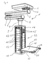
- Fig. 1 shows an isometric view of a medical supply unit 1.
- the medical supply unit 1 has a ceiling mount, which is covered by a ceiling panel 2.
- An upper tripod arm 3 is longitudinally connected at one end to the top via an upper pivot 4 with the ceiling mount.
- the middle pivot 6 is arranged in the longitudinal direction of the lower stand arm 5 at one end.
- a lower pivot 8 is arranged on the underside thereof, which in turn is connected to a spacer column 7.
- an upper end cover 9 is attached.
- the upper end cover 9, a lower end cover 10 and intervening elements form a support 32.
- the carrier 32 is cuboid shaped in this embodiment and has four long edges 11 and four intermediate longitudinal surfaces 12. In alternative embodiments, carriers with three, five or more long edges and long surfaces are possible. The basic shape is then not cuboid, but cylindrical with a suitable cross-section. Also, in other embodiments, medical care units may be provided with multiple carriers.
- a part of the long surfaces 12 is formed by built-in modules 13.
- the mounting modules 13 are arranged one above the other so that they form a continuous surface almost gap-free, which extends from the upper end cover 9 to the lower end cover 10.
- the built-in modules 13 are provided on the four sides of the carrier 32.
- the built-in modules 13 are designed as pure cover modules without internals, or as an electrical installation module 14 with built-in electrical sockets for powering medical devices, or as gas built-in modules 15 with gas taps or manometers, which serve to supply the medical apparatus with medical gases.
- a platform 16 is mounted for mounting or attaching medical apparatus or instruments.
- the platform 16 is equipped with operating handles 17, in which controls 18 are provided.
- the controls 18 are used to control actuators of the medical care unit, eg. B. controllable brakes in the hinges 4, 6 and 8.
- Laterally of the platform 16 extending rails 19.
- the rails 19 are used to hold other medical equipment or accessories.
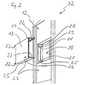
- Fig. 2 For example, one of the longitudinal surfaces 12 of the medical care unit carrier 32 is shown in an isometric view, with a mounting module 13 shown in a disassembled condition.
- the carrier 32 has an opening 20 in its longitudinal surface 12.
- resilient fastening elements 21 are provided, which are connectable to the carrier 32.
- two resilient fastening elements 21 are provided for each installation module 13. In other embodiments, however, only one resilient fastening element 21 may be provided laterally of the built-in module 13, respectively. Additionally or alternatively, fasteners may be provided on the top or bottom of the built-in module 13.
- the resilient fastening elements 21 are provided in this embodiment as separate components.
- the profiles of the carrier 32 may be formed so that the resilient fasteners 21 are already integrated therein.
- the resilient fasteners each have two resilient portions 25, one of which is shown on the upper fastener 21 and one on the lower fastener 21 within the opening 20, respectively. In order to increase the holding force, alternatively, however, a plurality of resilient portions 25 may be provided.
- the resilient fastening element 21 has a non-resilient portion 26.
- the non-resilient portion 26 serves as a vertical guide for the assembly of the mounting modules 13. It can also be provided a plurality of non-resilient portions 26.
- the resilient fastener 21 is made in this embodiment of spring steel, but it can also be used any other suitable materials.
- the installation module 13 has a front surface 23 which, when installed, forms a part of the longitudinal surface 12 together with the front surfaces 23 of the further installation modules 13.
- a cantilevered element 33 is provided on the opposite side of the front surface 23.
- the cantilevered elements 33 are formed on their sides 22 for attachment of the mounting modules 13 as described below.
- the front surface 23 is laterally formed in each case with a recessed shoulder, in which two openings 24 are provided on both sides.
- the openings 24 are suitable for allowing a special tool for releasing the built-in modules 13 to penetrate in the installed state to the resilient fastening elements 21. In other embodiments, only one breakthrough or multiple breakthroughs are possible.
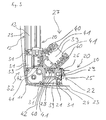
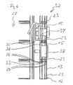
- FIG Fig. 3 A horizontal section through a portion of the carrier 32 is shown in FIG Fig. 3 shown.
- an interior space 27 is formed.
- the profile 28 has three hollow rails 39, each provided with insulating rails 40 with conductor rails 41.
- each additional mounting rails 42 are introduced.
- the hollow rails 39 are covered by the covering devices 31, in order to prevent the penetration of liquids into the hollow rails 39.
- the conductor rails 41 in the outwardly directed hollow rails 39 serve for the transmission of control signals for the operation of the medical supply unit 1, and possibly for the control of medical apparatus provided thereon.
- the Conductor rails, which are directed in the direction of the interior space 27, serve firstly for data transmission for operation of the medical supply unit, and secondly for the supply of electrical sockets or other electrical devices of the medical supply unit 1.
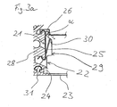
- Fig. 3a shows in detail how the profile 28 in each case in two areas, which face the built-in modules 13, has a configuration with two opposite ribs, which are suitable for the resilient fastening element 21 can be snapped.
- a positive connection and in the vertical direction generates a frictional connection, whereby the resilient fastening element 21 can be mounted at any height.
- the profile 28 can also be designed so that there is likewise a positive fit in the vertical direction.
- the installation module 13 has, as in Fig. 3 and Fig. 3a viewed from above, a certain contour.
- the sides 22 of the built-in module 13 are designed so that along their extension in the direction of the interior 27 in a region a recess 29 is arranged.
- the recess 29 has a locking surface 30 on the side which is farther from the front surface 23.
- the locking surface 30 is designed to include with the side 22 an angle ⁇ which is smaller than 90 °.
- an opening may be provided instead of the recess 29, which also has a locking surface 30 as described above.
- the non-resilient portion 26 of the resilient fastening element 21 protrudes, starting from the profile 28, in the direction of the opening 20, which is closed by the installation module 13. At a built-in module 13, the non-resilient portion 26 overlaps with the contour of the built-in module 13.
- the resilient portion 25 of the resilient fastener 21 When installing the mounting elements 13 of the resilient portion 25 of the resilient fastener 21 is pushed back by the contour of the mounting member 13, and upon further insertion of the mounting member 13 of the resilient fastener 21 of the resilient portion 25 enters into a positive engagement with the mounting member 13, since the resilient portion 25 during spring back during the installation process of the built-in module 13 engages with its end face in the recess 29 on the locking side 30 and the built-in module 13 is locked.
- the length of the resilient portion 25 is designed so that the point of contact between the resilient portion 25 and the locking surface 30 is approximately in the middle of the locking surface 30.
- the angle ⁇ and the distance of the locking surface 30 from the front surface 23 is selected so that even with maximum or minimum values in the tolerance chain, the resilient portion 25 is always in engagement with the locking surface 30.
- the apertures 24 are arranged so that after a removal or pushing away the cover 31, an access for a special tool is made possible, with which the resilient portion 25 can be pressed in the direction of the profile 28. It will the engagement between the resilient portion 25 and the locking side 30 is released and the installation module 13 is unlocked and can be pulled out of the carrier 32.
- the tool is designed so that it pushes back the resilient portion 25 when pressed in the direction of the inner space 27, and automatically pulls the built-in module 13 from the opening 20 upon retraction of the tool. Only the pushing back of the resilient portion 25 without the automatic extraction can also be done using a conventional tool, such as a screwdriver or a pen.
- the apertures 24 are covered by the cover devices 31 in order to improve the hygienic conditions.
- FIG. 4 a vertical section through a portion of the carrier 32 is shown.
- the front surfaces 23 of the individual installation modules 13 are shown, which form part of the longitudinal surface 12.
- the built-in modules 13 have at the upper ends of the lateral contour of the front surface 23, starting from each a right-angled recessed heel.
- the lateral contour of the built-in modules 13 is provided in each case with a projection downwards, which is complementary to the paragraphs formed on the top thereof.
- This configuration results in a meshing of the shoulders and the projections, which avoids that liquids that run down along the front surface 23 can penetrate into the carrier 32.
- the overlapping lower portion of the front surface over the shoulder at the upper end of the front surface 23, the formation of an inwardly continuous gap between the mounting modules 13 is prevented, so that even with the occurrence of tolerances, the penetration of the liquids is prevented.
- the cheeks which form the cantilevered elements 33 on the front side 23 opposite side, are provided with a plurality of grooves 34 having different widths.
- the grooves 34 of the upper cheek 33 and the grooves 34 of the lower cheek 33 are respectively disposed opposite to each other. In alternative embodiments, the number of grooves 34 may vary and the widths of the grooves 34 may be different.
- the cheeks 33 with the grooves 34 serve as attachment means for attachments on the front surface 23 opposite side.
- each gas sockets 37 or 38 gauge are installed.
- the gas sockets 37 or pressure gauge 38 are attached to the gas installation module 15 by means of attachment parts in the form of fastening profiles 35, 36.
- the fastening profile 35, 36 has a substantially U-shaped contour, with the closed leg of the horizontal U pointing in the direction of the interior 27 of the carrier 32. At the two ends of the U-shaped contour lying opposite the closed region, the ends of the legs are bent by 180 °. They thus form engagement elements on the outside of the fastening profiles 35, 36.
- the dimensions of the fastening profile 35 are dependent on the type and mounting options of the gas sockets and pressure gauges.
- the fastening profiles can vary in depth, width, and contour.
- the mounting profile can be either in the orientation as in Fig. 4 be shown installed, or rotated through 180 °, so that the closed area of the profile in Fig. 4 located on the right side.
- the fastening profile is reduced to a mounting plate.
- the engaging elements formed on the fastening profiles 35, 36 and the mounting plate are respectively in the grooves 34, which serve as fastening means are provided at different distances from the front surface 23, inserted.
- the gas outlets and pressure gauges are connected to the central gas supply system via hoses or pipes (not shown).
- the electrical sockets are connected to the in Fig. 3 shown conductor rails 41 connected or alternatively wired directly to the power grid.
- the dimension of the built-in modules 13 in the vertical direction ie their height, is selected so that, starting from this, the further height dimensions each amount to an integer multiple thereof.
- individual modules can be easily replaced or a plurality of modules can be replaced by a module with a larger dimension, the front surface 23 is not interrupted.
- the resilient fasteners 21 are clipped by means of a device to the profile 28, that the resilient fasteners 21 a distance from each other and also from the upper end cover 9 and the lower end cover 10, so that the built-in modules 13 clipped according to their height dimensions can be.
- any small gaps that may arise due to tolerances are distributed over the entire front surface 23, so that not at one end of the front surface 23, a larger gap.
Description
Die Erfindung betrifft eine medizinische Versorgungseinheit mit Einbaumodulen. Insbesondere betrifft die Erfindung eine medizinische Versorgungseinheit mit Einbaumodulen, die ohne Werkzeug montierbar und in einem vorbestimmten Raster an beliebigen Stellen montierbar sind.The invention relates to a medical supply unit with built-in modules. In particular, the invention relates to a medical supply unit with built-in modules that can be mounted without tools and mounted in a predetermined grid at any point.
Im medizinischen Bereich, insbesondere in der Intensivmedizin oder in der Chirurgie ist es erforderlich, eine Vielzahl elektrischer und elektronischer medizinischer Apparate gemeinsam in einem räumlichen Bereich zu betreiben und so anzuordnen, dass sie sich einerseits nahe am Patienten befinden, aber andererseits den Zugang zum Patienten nicht behindern. Dies erfordert in der Regel eine gewisse Mobilität dieser Apparate sowie eine Flexibilität der Anbringungsmöglichkeiten an einer medizinischen Versorgungseinheit.In the medical field, in particular in intensive care medicine or in surgery, it is necessary to operate a large number of electrical and electronic medical apparatuses together in a spatial area and to arrange them close to the patient on the one hand, but not access to the patient on the other hand hinder. This usually requires a certain mobility of these devices as well as a flexibility of the attachment possibilities to a medical supply unit.
Im Hinblick auf die hygienischen Anforderungen ist es anzustreben, die Leitungen zwischen den Anschlüssen an der medizinischen Versorgungseinheit und den medizinischen Apparaten möglichst kurz zu gestalten. Daher ist es wünschenswert, dass sich Datenanschlussstellen und die Entnahmestellen, nämlich Elektrosteckdosen oder Gassteckdosen in der Nähe der jeweiligen Geräte befinden, um die Leitungslängen möglichst kurz zu gestalten. Bei einer Veränderung der Konfiguration oder der Positionierung der medizinischen Apparate ist es daher auch vorteilhaft, die Entnahmestellen so anzuordnen, dass sie räumlich günstig, nämlich in geringem Abstand zu den medizinischen Apparaten angeordnet sind.With regard to the hygienic requirements, it is desirable to make the lines between the connections to the medical supply unit and the medical apparatuses as short as possible. Therefore, it is desirable that data ports and the tapping points, namely, electrical outlets or gas outlets, be in the vicinity of the respective devices to minimize cable lengths. When changing the configuration or the positioning of the medical apparatus, it is therefore also advantageous to arrange the removal points so that they are spatially favorable, namely arranged at a small distance to the medical apparatuses.
Aus hygienischen Gründen ist es weiterhin anzustreben, dass keine Befestigungsmittel, wie z. B. Schrauben, von außen sichtbar sind, da dies die Möglichkeit zur Reinigung beeinträchtigt, und zusätzliche Spalte und Öffnungen damit geschaffen werden, in denen sich Krankheitserreger festsetzen können.For reasons of hygiene, it is still desirable that no fasteners, such. As screws, are visible from the outside, as this impairs the possibility for cleaning, and additional gaps and openings are created so that pathogens can accumulate.
Für eine wirtschaftliche Montage der medizinischen Versorgungseinheiten ist es anzustreben, möglichst standardisierte Module einzusetzen, die dann ohne Verwendung von Werkzeugen in der medizinischen Versorgungseinheit montiert werden können. Die Demontage der Module darf jedoch aus Sicherheitsgründen nur mit Hilfe von Werkzeug ermöglicht werden.For economical assembly of the medical supply units, it is desirable to use as standardized modules as possible, which can then be mounted without the use of tools in the medical supply unit. For safety reasons, the modules may only be dismantled with the help of tools.
Aus dem Stand der Technik sind medizinische Versorgungseinheiten, z. B. Deckenversorgungseinheiten, bekannt, die einen oder mehrere Träger für Entnahmestellen aufweisen, die ein Grundgerüst aus Profilen aufweisen, wobei Datenanschlussstellen oder die Entnahmestellen für medizinische Gase und elektrischen Strom mit speziellen Halteblechen in dem Grundgerüst befestigt sind. Die Grundkörper der Entnahmestellen werden dann mit Hilfe von Abdeckplatten, die mit den entsprechenden Öffnungen für die spezifische Konfiguration der Entnahmestellen angefertigt werden, abgedeckt. Diese Platten werden in der Regel mit Hilfe von Schrauben an dem Grundgerüst befestigt.From the prior art medical care units, z. As ceiling supply units, known which have one or more carriers for sampling points, which have a skeleton of profiles, data terminals or the collection points for medical gases and electric power are fixed with special holding plates in the skeleton. The bodies of the tapping points are then covered by cover plates made with the appropriate openings for the specific configuration of the tapping points. These plates are usually fastened by means of screws to the skeleton.
Die Offenlegungsschrift
Das Prinzip dieses Aufbaus bringt aber den Nachteil mit sich, dass die Konfiguration und die Anordnung der Entnahmestellen festgelegt sind. Eine nachträgliche Veränderung der Position oder Hinzunahme oder Weglassen von Entnahmestellen erfordert immer die Anfertigung einer neuen Abdeckplatte, so dass der Aufwand für nachträgliche Veränderungen groß wird. Auch die Montage ist nicht optimal zu gestalten, da keine vorgefertigten Module in den Träger der medizinischen Versorgungseinheit eingebaut werden können, sondern die Einzelteile jeweils sukzessive in den jeweiligen Träger eingebaut werden müssen, was jeweils durch aufwendige Arbeitsschritte geschieht, da die Baugruppen und Bauteile einzeln in den Träger geschraubt werden müssen.However, the principle of this structure has the disadvantage that the configuration and the arrangement of the sampling points are fixed. A subsequent change in the position or addition or omission of sampling points always requires the preparation of a new cover plate, so that the cost of subsequent changes is large. The assembly is not optimal, since no prefabricated modules installed in the carrier of the medical supply unit can be, but each of the items must be successively installed in the respective carrier, which is done by consuming steps, since the modules and components must be screwed individually into the carrier.
Es ist Aufgabe der Erfindung, diese Probleme zu lösen. Insbesondere ist es Aufgabe der Erfindung, eine medizinische Versorgungseinheit bereitzustellen, die es ermöglicht, modulare, vorgefertigte Baugruppen in einfacher Weise in die medizinische Versorgungseinheit einzubauen, und die eine große Flexibilität in der Anordnung der Baugruppen erlaubt.It is an object of the invention to solve these problems. In particular, it is an object of the invention to provide a medical supply unit, which makes it possible to easily incorporate modular, prefabricated modules in the medical supply unit, and allows a great flexibility in the arrangement of the modules.
Diese Aufgabe wird durch die Vorrichtung gemäß Anspruch 1 gelöst. Vorteilhafte Weiterentwicklungen sind Gegenstand der abhängigen Ansprüche.This object is achieved by the device according to claim 1. Advantageous developments are the subject of the dependent claims.
Gemäß einem Aspekt der Erfindung weist die medizinische Versorgungseinheit einen Träger mit mindestens drei Langkanten, mindestens drei Langflächen und einem Innenraum auf. Mindestens eine der Langflächen ist mit mindestens einer Öffnung versehen, und an mindestens zwei Seiten der Öffnung ist mindestens ein federndes Befestigungselement vorgesehen, das in Richtung der Öffnung ragt.According to one aspect of the invention, the medical supply unit has a carrier with at least three long edges, at least three longitudinal surfaces and an inner space. At least one of the longitudinal surfaces is provided with at least one opening, and at least two sides of the opening at least one resilient fastening element is provided, which projects in the direction of the opening.
Die Erfindung wird anhand eines Ausführungsbeispiels unter Bezugnahme auf die begleitenden Figuren beschrieben.
- Fig. 1
- ist eine isometrische Ansicht eines Ausführungsbeispiels der erfindungsgemäßen medizinischen Versorgungseinheit als Deckenstativ.
- Fig. 2
- zeigt eine isometrische Ansicht auf eine Langfläche des Trägers mit einem herausgenommenen Einbaumodul.
- Fig. 3
- ist ein horizontaler Schnitt durch einen Bereich des Trägers.
- Fig. 3a
- zeigt eine vergrößerte Detailansicht des Bereichs des Trägers von
Fig. 3 mit der Klipverbindung zwischen dem federnden Befestigungselement im Eingriff mit dem Einbaumodul. - Fig. 4
- zeigt einen vertikalen Schnitt durch einen Abschnitt des Trägers.
- Fig. 1
- is an isometric view of an embodiment of the medical supply unit according to the invention as a ceiling stand.
- Fig. 2
- shows an isometric view of a long surface of the carrier with a removed module built-in.
- Fig. 3
- is a horizontal section through an area of the carrier.
- Fig. 3a
- shows an enlarged detail view of the area of the carrier of
Fig. 3 with the clip connection between the resilient fastener engaged with the mounting module. - Fig. 4
- shows a vertical section through a portion of the carrier.
Im Folgenden wird der Gesamtaufbau eines Ausführungsbeispiels einer erfindungsgemäßen medizinischen Versorgungseinheit überblicksweise beschrieben.In the following, the overall structure of an exemplary embodiment of a medical supply unit according to the invention will be described in an overview.
Der Träger 32 ist in diesem Ausführungsbeispiel quaderförmig gestaltet und weist vier Langkanten 11 und vier dazwischen liegende Langflächen 12 auf. In alternativen Ausführungsformen sind auch Träger mit drei, fünf oder mehreren Langkanten und Langflächen möglich. Die grundsätzliche Form ist dann nicht quaderförmig, sondern zylindrisch mit einem geeigneten Querschnitt. Auch können in anderen Ausführungsformen medizinische Versorgungseinheiten mit mehreren Trägern vorgesehen sein.The
Ein Teil der Langflächen 12 wird durch Einbaumodule 13 gebildet. Die Einbaumodule 13 sind so übereinander angeordnet, dass sie nahezu spaltfrei eine durchgehende Fläche bilden, die sich von dem oberen Abschlussdeckel 9 bis zu dem unteren Abschlussdeckel 10 erstreckt. Die Einbaumodule 13 sind an den vier Seiten des Trägers 32 vorgesehen. Die Einbaumodule 13 sind als reine Abdeckmodule ohne Einbauten, oder als Elektro-Einbaumodul 14 mit eingebauten Elektrosteckdosen zur Stromversorgung von medizinischen Apparaten, oder als Gas-Einbaumodule 15 mit Gasentnahmestellen oder Manometern, die zur Versorgung der medizinischen Apparate mit medizinischen Gasen dienen, gestaltet.A part of the
An der in
In
Die federnden Befestigungselemente 21 sind in diesem Ausführungsbeispiel als separate Bauteile vorgesehen. Alternativ können auch die Profile des Trägers 32 so ausgebildet sein, dass die federnden Befestigungselemente 21 bereits darin integriert sind. Die federnden Befestigungselemente weisen jeweils zwei federnde Abschnitte 25 auf, von denen jeweils einer an dem oberen Befestigungselement 21 und einer an dem unteren Befestigungselement 21 innerhalb der Öffnung 20 gezeigt ist. Um die Haltekraft zu erhöhen, können alternativ aber auch mehrere federnde Abschnitte 25 vorgesehen sein. Weiterhin weist das federnde Befestigungselement 21 einen nicht federnden Abschnitt 26 auf. Der nicht federnde Abschnitt 26 dient als vertikale Führung für die Montage der Einbaumodule 13. Es können auch mehrere nicht federnde Abschnitte 26 vorgesehen sein. Das federnde Befestigungselement 21 ist in diesem Ausführungsbeispiel aus Federstahl angefertigt, es können aber auch jegliche andere geeignete Materialien verwendet werden.The
Das Einbaumodul 13 weist eine Frontfläche 23 auf, die im eingebauten Zustand gemeinsam mit den Frontflächen 23 der weiteren Einbaumodule 13 einen Teil der Langfläche 12 bildet. An der Oberseite und an der Unterseite des Einbaumoduls 13 ist auf der gegenüberliegenden Seite der Frontfläche 23 jeweils ein auskragendes Element 33 vorgesehen. Die auskragenden Elemente 33 sind an ihren Seiten 22 zur Befestigung der Einbaumodule 13 wie nachstehend beschrieben geformt. Die Frontfläche 23 ist seitlich jeweils mit einem vertieften Absatz geformt, in denen an beiden Seiten jeweils zwei Durchbrüche 24 vorgesehen sind. Die Durchbrüche 24 sind geeignet, um ein spezielles Werkzeug zum Lösen der Einbaumodule 13 im eingebauten Zustand zu den federnden Befestigungselementen 21 eindringen zu lassen. In anderen Ausführungsformen ist auch nur ein Durchbruch oder sind mehrere Durchbrüche möglich.The
Ein horizontaler Schnitt durch einen Bereich des Trägers 32 ist in
Das Profil 28 weist drei Hohlschienen 39 mit jeweils darin vorgesehenen Isolierschienen 40 mit Leiterschienen 41 auf. In die äußeren Hohlschienen 39 sind jeweils zusätzlich Befestigungsschienen 42 eingebracht. Die Hohlschienen 39 werden aus hygienischen Gründen durch die Abdeckvorrichtungen 31 abgedeckt, um ein Eindringen von Flüssigkeiten in die Hohlschienen 39 zu vermeiden. Die Leiterschienen 41 in den nach außen gerichteten Hohlschienen 39 dienen zur Übertragung von Steuersignalen zum Betrieb der medizinischen Versorgungseinheit 1, und ggf. zur Ansteuerung von daran vorgesehenen medizinischen Apparaten. Die Leiterschienen, die in Richtung des Innenraums 27 gerichtet sind, dienen zum einen zur Datenübertragung zum Betrieb der medizinischen Versorgungseinheit, und zum anderen zur Versorgung von Elektrosteckdosen oder sonstigen elektrischen Einrichtungen der medizinischen Versorgungseinheit 1.The
In
Das Einbaumodul 13 weist, wie in
Der nicht federnde Abschnitt 26 des federnden Befestigungselements 21 ragt, ausgehend von dem Profil 28, in Richtung der Öffnung 20, die durch das Einbaumodul 13 verschlossen wird. Bei einem eingebauten Einbaumodul 13 überschneidet sich der nicht federnde Abschnitt 26 mit der Kontur des Einbaumoduls 13. Durch eine geeignete vertikale Positionierung der federnden Befestigungselemente 21 dient der nicht federnde Abschnitt 26 somit als Führung in vertikaler Richtung für die Einbauelemente 13, da die Einbauelemente 13 auf dem nicht federnden Abschnitt 26 aufliegen.The
Beim Einbau der Einbauelemente 13 wird der federnde Abschnitt 25 des federnden Befestigungselements 21 durch die Kontur des Einbauelements 13 zurückgedrückt, und bei einem weitere Einschieben des Einbauelements 13 des federnden Befestigungselements 21 gelangt der federnde Abschnitt 25 in einen formschlüssigen Eingriff mit dem Einbauelement 13, da der federnde Abschnitt 25 beim Zurückfedern während des Einbauvorgangs des Einbaumoduls 13 mit seiner Stirnseite in die Vertiefung 29 an der Verriegelungsseite 30 eingreift und das Einbaumodul 13 dabei verriegelt. Die Länge des federnden Abschnitts 25 ist dabei so ausgelegt, dass der Berührpunkt zwischen dem federnden Abschnitt 25 und der Verriegelungsfläche 30 etwa in der Mitte der Verriegelungsfläche 30 liegt. Somit kann bei einem Auftreten von Form- und Lagetoleranzen des Profils 28, des federnden Befestigungselements 21 und des Einbaumoduls 13, ein spielfreier Einbau des Einbauelements 13 gewährleistet werden. Der Winkel α und die Entfernung der Verriegelungsfläche 30 von der Frontfläche 23 ist so gewählt, dass auch bei maximalen oder minimalen Werten in der Toleranzkette, der federnde Abschnitt 25 immer im Eingriff mit der Verriegelungsfläche 30 ist.When installing the mounting
Die Durchbrüche 24 sind so angeordnet, dass nach einem Entfernen oder Wegdrücken der Abdeckvorrichtung 31 ein Zugang für ein spezielles Werkzeug ermöglicht wird, mit dem der federnde Abschnitt 25 in Richtung des Profils 28 gedrückt werden kann. Dabei wird der Eingriff zwischen dem federnden Abschnitt 25 und der Verriegelungsseite 30 aufgehoben und das Einbaumodul 13 wird entriegelt und kann aus dem Träger 32 herausgezogen werden. Günstigerweise ist das Werkzeug so gestaltet, dass es beim Eindrücken in Richtung des Innenraums 27 den federnden Abschnitt 25 zurückdrückt, und bei einem Zurückziehen des Werkzeugs das Einbaumodul 13 aus der Öffnung 20 automatisch herauszieht. Nur das Zurückdrücken des federnden Abschnitts 25 ohne das automatische Herausziehen kann auch mit Hilfe eines konventionellen Werkzeugs, wie z.B. eines Schraubendrehers oder eines Stifts erfolgen.The
Nach dem Einbau der Einbaumodule 13 werden die Durchbrüche 24 durch die Abdeckvorrichtungen 31 abgedeckt, um die hygienischen Bedingungen zu verbessern.After installation of the built-in
In
Die Wangen, die die auskragenden Elemente 33 auf der der Frontseite 23 gegenüber liegenden Seite bilden, sind mit mehreren Nuten 34, die verschiedene Breiten aufweisen, versehen. Die Nuten 34 der oberen Wange 33 und die Nuten 34 der unteren Wange 33 sind jeweils gegenüberliegend angeordnet. In alternativen Ausführungsformen können die Anzahl der Nuten 34 abweichen sein, und die Breiten der Nuten 34 anders ausgeführt sein. Die Wangen 33 mit den Nuten 34 dienen als Befestigungsmittel für Anbauteile auf der der Frontfläche 23 gegenüber liegenden Seite.The cheeks, which form the
In die in der
Die Befestigung von Elektrosteckdosen in Elektroeinbaumodulen 14 erfolgt grundsätzlich in der gleichen Art und Weise. Abhängig von der Art und der Befestigungsmöglichkeit der Elektrosteckdosen und Gassteckdosen oder Manometer, ist auch eine direkte Befestigung an der vorderen Platte, die die Frontfläche 23 bildet, möglich.The attachment of electrical sockets in
Die Gassteckdosen und Manometer werden über nicht gezeigte Schläuche oder Rohre mit der zentralen Gasversorgungsanlage verbunden. Die Elektrosteckdosen werden an den in
Die Abmessung der Einbaumodule 13 in vertikaler Richtung, also deren Höhe, ist so gewählt, dass ausgehend davon die weiteren Höhenabmessungen jeweils ein ganzzahliges Vielfaches davon betragen. Somit können einzelne Module leicht ausgewechselt werden oder eine Mehrzahl von Modulen durch ein Modul mit einer größeren Abmessung ersetzt werden, wobei die Frontfläche 23 nicht unterbrochen wird.The dimension of the built-in
Das Austauschen von Modulen, um die jeweiligen Entnahmestellen in die Nähe der medizinischen Apparate anzuordnen, so dass die Versorgungsleitungen möglichst kurz ausgeführt werden können, ist hier leicht möglich. Bei einer Veränderung der benötigten Konfiguration der Entnahmestellen ist auch ein Nachrüsten von Gassteckdosen, Elektrosteckdosen oder Datenanschlüssen leicht möglich, ohne ganze Abdeckplatten neu anzufertigen und einen hohen Montageaufwand aufbringen zu müssen.The replacement of modules to place the respective donor sites in the vicinity of the medical equipment, so that the supply lines can be made as short as possible, is easily possible here. In a change in the required configuration of the sampling points and retrofitting of gas sockets, electrical sockets or data connections is easily possible to make new entire cover plates and have to raise a high assembly costs.
Bei der Erstmontage werden die federnden Befestigungselemente 21 mit Hilfe einer Vorrichtung so an das Profil 28 angeklipst, dass die federnden Befestigungselemente 21 einen Abstand zueinander und ebenso von dem oberen Abschlussdeckel 9 und dem unteren Abschlussdeckel 10 aufweisen, so dass die Einbaumodule 13 entsprechend ihren Höhenabmessungen angeklipst werden können. Damit werden eventuell auftretende kleine Spalte, die durch Toleranzen entstehen können, über die ganze Frontfläche 23 verteilt, so dass nicht an einem Ende der Frontfläche 23 ein größerer Spalt entsteht.In the initial assembly, the
Claims (14)
- Medical supply unit (1) comprising a carrier (32), wherein
the carrier (32) comprises at least three longitudinal edges (11), at least three longitudinal faces (12) and an internal space (27), and
it comprises at least one opening (20) in at least one longitudinal face (12), wherein the opening (20) is closable by a built-in module (13), characterized in
that the carrier (32) is formed such that it respectively comprises at least one resilient fixing element (21) protruding towards the opening (20) at at least two faces of the opening (20), and
that a resilient portion (25) of the resilient fixing element (21) is formed such that it is able to be brought into a positive engagement with the built-in module (13). - Medical supply unit (1) according to claim 1, characterized in that
the resilient fixing element (21) is a separate element which is connectable to the carrier (32). - Medical supply unit (1) according to claim 2, characterized in that
the carrier (32) and the resilient fixing element (21) are formed such that they have a positive connection in one direction. - Medical supply unit (1) according to any of the claims 1 to 3, characterized in that
the resilient fixing element (21) comprises at least one resilient portion (25) as a locking element and at least one non-resilient portion (26) as a guide which respectively protrude towards the center of the opening (20). - Medical supply unit (1) according to any of the claims 2 to 4, characterized in that
the resilient fixing element (21) is made of spring steel. - Medical supply unit (1) according to any of the claims 1 to 5, including the built-in module (13) which is suitable for being inserted into the carrier (32), wherein the built-in module (13) comprises:a front face (23) adapted to form a part of the longitudinal face (12) in a condition in which the built-in module (13) is inserted into the carrier (32),at least two opposite faces (22), adjacent to the front face (23), which are adapted such that at least one resilient fixing element (21) engages with the faces (22) such that a positive connection is provided between the carrier (32) or the fixing element (21) and the built-in module (13),characterized in that,starting from the front face (23), a rectangular recessed step is provided at the upper end of the lateral contour of the built-in module (13), andthe lateral contour at the lower side of the front face (23) is provided with a downward protrusion which is formed in a complementary manner with respect to the step at the upper end.
- Medical supply unit (1) according to claim 6, characterized in that
the faces (22) comprise a recess (29) or an opening which comprises a locking face (30), distant from the front face (23), which encloses an angle (α) smaller than 90° with the face of the built-in module (13). - Medical supply unit (1) according to any of the claims 6 or 7, characterized in that
in a lateral recessed step of the front face (23), the front face (23) comprises at least one opening (24) having a size and a position which is suitable for allowing a tool to penetrate in order to release the engagement of the resilient fixing element (21). - Medical supply unit (1) according to any of the claims 6 to 8, characterized in that
the built-in module (13) comprises fixing means (34) for attachments (35, 36) at the side opposite to the front face (23). - Medical supply unit (1) according to claim 9, characterized in that
the built-in module (13) comprises protruding elements (33) and the fixing means (34) are arranged at the protruding elements (33). - Medical supply unit (1) according to claim 10, characterized in that
the protruding element (33) comprises several fixing means (34) at different distances from the front face (23). - Medical supply unit (1) according to any of the claims 9 to 11, characterized in that
the attachment (35, 36) is formed as to be a fixing profile for gas outlets or electrical outlets (37). - Medical supply unit (1) according to any of the claims 9 to 11, characterized in that
the attachment (35, 36) is formed as to be a fixing plate for gas outlets or electrical outlets (37). - Medical supply unit (1) according to claim 8 or claim 8 and any of the claims 9 to 13, characterized in that
the carrier (32) comprises a covering device (31), preferably a lip of elastic material, which closes the opening (24) for terminating the engagement of the resilient fixing element (21).
Priority Applications (5)
| Application Number | Priority Date | Filing Date | Title |
|---|---|---|---|
| EP09159613.0A EP2248504B1 (en) | 2009-05-07 | 2009-05-07 | Medical supply unit with built-in modules |
| PL09159613T PL2248504T3 (en) | 2009-05-07 | 2009-05-07 | Medical supply unit with built-in modules |
| CN201010214396.1A CN101889899B (en) | 2009-05-07 | 2010-05-07 | Medical supply unit with built-in modules |
| US12/775,672 US8376302B2 (en) | 2009-05-07 | 2010-05-07 | Attaching modules to a medical supply unit |
| HK11104007.0A HK1146528A1 (en) | 2009-05-07 | 2011-04-20 | Medical supply unit with built-in modules |
Applications Claiming Priority (1)
| Application Number | Priority Date | Filing Date | Title |
|---|---|---|---|
| EP09159613.0A EP2248504B1 (en) | 2009-05-07 | 2009-05-07 | Medical supply unit with built-in modules |
Publications (2)
| Publication Number | Publication Date |
|---|---|
| EP2248504A1 EP2248504A1 (en) | 2010-11-10 |
| EP2248504B1 true EP2248504B1 (en) | 2013-11-06 |
Family
ID=41119560
Family Applications (1)
| Application Number | Title | Priority Date | Filing Date |
|---|---|---|---|
| EP09159613.0A Active EP2248504B1 (en) | 2009-05-07 | 2009-05-07 | Medical supply unit with built-in modules |
Country Status (5)
| Country | Link |
|---|---|
| US (1) | US8376302B2 (en) |
| EP (1) | EP2248504B1 (en) |
| CN (1) | CN101889899B (en) |
| HK (1) | HK1146528A1 (en) |
| PL (1) | PL2248504T3 (en) |
Families Citing this family (6)
| Publication number | Priority date | Publication date | Assignee | Title |
|---|---|---|---|---|
| JP2015503968A (en) * | 2012-01-04 | 2015-02-05 | フレゼニウス ヴィアル エスアーエスFresenius Vial SAS | Arrangement structure of rack and medical equipment |
| US9730851B2 (en) | 2012-09-07 | 2017-08-15 | Allen Medical Systems, Inc. | Surgical support system |
| US9107792B2 (en) | 2012-09-07 | 2015-08-18 | Allen Medical Systems, Inc. | Carriage for a surgical boot of a hip distractor |
| US8986039B2 (en) * | 2013-02-19 | 2015-03-24 | Phoenix Contact Development and Manufacturing, Inc. | Shelf lighting connector assembly |
| CN103908350B (en) | 2014-04-30 | 2016-08-17 | 迈柯唯医疗设备(苏州)有限公司 | Medical hoist tower casing |
| CN103919615B (en) | 2014-04-30 | 2017-01-25 | 迈柯唯医疗设备(苏州)有限公司 | Medical crane box and stand columns for medical crane box |
Family Cites Families (23)
| Publication number | Priority date | Publication date | Assignee | Title |
|---|---|---|---|---|
| US4048768A (en) | 1976-09-30 | 1977-09-20 | Harter Corporation | Device for lockably securing appurtenances to a decorative wall |
| DE3714196C2 (en) * | 1987-04-29 | 1996-04-04 | Trilux Lenze Gmbh & Co Kg | Supply bar for intensive care |
| US5023396A (en) * | 1989-03-10 | 1991-06-11 | Square D Company | Pop-up service fitting |
| ES2049858T3 (en) * | 1989-05-24 | 1994-05-01 | Zumtobel Licht | BUILT-IN BOX FOR PLACING INCORPORATION DEVICES, PREFERABLY ELECTRICAL INCORPORATION DEVICES. |
| US5165640A (en) | 1991-10-04 | 1992-11-24 | Williams 3Rd James W | Spring clip for perforated board tool holders |
| DE4239625C1 (en) | 1992-11-26 | 1993-08-05 | Fresenius Ag, 6380 Bad Homburg, De | Medical transfusion equipment connecting column - forms connection with data exchange equipment and has two conductors secured by clamp with jaws and electrical contacts |
| US5348485A (en) | 1993-04-12 | 1994-09-20 | Electronic Retailing Systems Int'l Inc. | Electronic price display system with vertical rail |
| DE29505072U1 (en) | 1995-03-25 | 1996-08-01 | Trilux Lenze Gmbh & Co Kg | Supply unit for a medical care station |
| DE29617895U1 (en) * | 1996-10-15 | 1997-01-02 | Trilux Lenze Gmbh & Co Kg | Supply bar for intensive care |
| DE19715156C1 (en) | 1997-04-11 | 1998-08-20 | Bankamp Leuchten Gmbh | Mounting system for electrical power bus=bars with shaped moulded rail |
| US5907126A (en) * | 1997-09-04 | 1999-05-25 | The Wiremold Company | Metal electrical outlet box with push-in screws for mounting electrical device |
| US6196649B1 (en) * | 1998-01-15 | 2001-03-06 | Steris Corporation | Convertible surgical equipment and appliance support system |
| US5975318A (en) | 1998-02-13 | 1999-11-02 | Display Technologies, Inc. | Display shelf assembly and bracket useful therein |
| US6070841A (en) | 1998-03-13 | 2000-06-06 | Advertising Display Company | Universal sidekick mount bracket |
| US6230910B1 (en) | 1998-03-31 | 2001-05-15 | Auto-Lok, Inc. | Self-locking beam clip |
| JP2002521628A (en) * | 1998-07-22 | 2002-07-16 | ヴァンプラー アクチエンゲゼルシャフト | A device for supplying air to a user staggered by the compressed air line |
| US6056561A (en) | 1999-02-08 | 2000-05-02 | Lin; Shan Chaing | Adapter and track arrangement for lighting fixtures |
| DE10057556A1 (en) | 2000-11-21 | 2002-05-23 | Kreuzer Gmbh & Co Ohg | Tripod head for medical surveillance and treatment systems with carrier profile and apparatus carriage |
| WO2006115495A1 (en) * | 2005-04-27 | 2006-11-02 | Byrne Norman R | Multiple circuit receptacles |
| US8017865B1 (en) * | 2005-06-06 | 2011-09-13 | Taymac Corporation | Collapsible while-in-use electrical outlet cover assembly |
| CA2556124C (en) * | 2006-08-15 | 2014-04-22 | Inscape Corporation | Stacked cabinet structure with intermediate raceway |
| DE102007053327A1 (en) * | 2007-11-08 | 2009-05-14 | Trumpf Medizin Systeme Gmbh + Co.Kg | Medical supply unit for power supply and data transmission in medical apparatus |
| US8123185B2 (en) | 2008-03-24 | 2012-02-28 | Ss3 Storage Systems, L.L.C. | Bracket release mechanism |
-
2009
- 2009-05-07 PL PL09159613T patent/PL2248504T3/en unknown
- 2009-05-07 EP EP09159613.0A patent/EP2248504B1/en active Active
-
2010
- 2010-05-07 US US12/775,672 patent/US8376302B2/en active Active
- 2010-05-07 CN CN201010214396.1A patent/CN101889899B/en active Active
-
2011
- 2011-04-20 HK HK11104007.0A patent/HK1146528A1/en not_active IP Right Cessation
Also Published As
| Publication number | Publication date |
|---|---|
| PL2248504T3 (en) | 2014-05-30 |
| EP2248504A1 (en) | 2010-11-10 |
| US8376302B2 (en) | 2013-02-19 |
| CN101889899A (en) | 2010-11-24 |
| CN101889899B (en) | 2014-07-23 |
| HK1146528A1 (en) | 2011-06-17 |
| US20100284731A1 (en) | 2010-11-11 |
Similar Documents
| Publication | Publication Date | Title |
|---|---|---|
| EP2248503B1 (en) | Medical supply unit with lockable adapters | |
| EP2058911B1 (en) | Medical supply unit for supplying electricity and transferring data in medical devices | |
| EP2248504B1 (en) | Medical supply unit with built-in modules | |
| EP1336065B1 (en) | Tripod head, especially for a medical monitoring and supply device, carrier profile for such a tripod head and appliance trolley | |
| DE202015101776U1 (en) | Rangierwabe | |
| DE102006015317B4 (en) | Device installation kit for arranging a device in an electrical switchgear | |
| EP3281253B1 (en) | Patchboard | |
| EP2523281B1 (en) | Cable channel | |
| EP1443617B1 (en) | Support rail arrangement for electrical cabinets | |
| DE10136680B4 (en) | switch cabinet | |
| DE19908350A1 (en) | Device for mounting or wiring electrical and/or electronic components in electrical cabinet, has holding device for removably attaching cover strips near intermediate space, forming connection to cover strips | |
| EP2831970B1 (en) | System module for electroinstallation technology for buildings and door communication technology | |
| EP3607624B1 (en) | Arrangement of a base and an electrical cabinet frame mounted thereon and corresponding alignement of electrical cabinets | |
| EP3419128A1 (en) | Power strip for a distribution box | |
| EP2503643B1 (en) | Clamp device for connecting electrical lines and tool for same | |
| DE4013985A1 (en) | Detachable mounting plate for plug-in chassis - has gapped ends to prevent jamming while fitting | |
| EP2418746A2 (en) | Device socket for installation devices | |
| DE102009052997A1 (en) | Device for connecting electrical installation devices | |
| EP2372852A2 (en) | Meter- or distribution cabinet | |
| DE102019134828A1 (en) | Fastening system and control cabinet | |
| WO2012089191A1 (en) | Connecting element for creating media cells | |
| DD235769A1 (en) | MOUNTING FOR ELECTRICAL APPLIANCES IN BLANKED MOUNTING TECHNOLOGY | |
| DE102018118451A1 (en) | Holding device for a patch panel and patch panel | |
| DE202010001480U1 (en) | Protective device for a control device and control unit equipped therewith | |
| EP2426798A1 (en) | Holding device for an electric device |
Legal Events
| Date | Code | Title | Description |
|---|---|---|---|
| PUAI | Public reference made under article 153(3) epc to a published international application that has entered the european phase |
Free format text: ORIGINAL CODE: 0009012 |
|
| AK | Designated contracting states |
Kind code of ref document: A1 Designated state(s): AT BE BG CH CY CZ DE DK EE ES FI FR GB GR HR HU IE IS IT LI LT LU LV MC MK MT NL NO PL PT RO SE SI SK TR |
|
| 17P | Request for examination filed |
Effective date: 20110415 |
|
| RAP1 | Party data changed (applicant data changed or rights of an application transferred) |
Owner name: TRUMPF MEDIZIN SYSTEME GMBH + CO. KG |
|
| 17Q | First examination report despatched |
Effective date: 20120104 |
|
| GRAP | Despatch of communication of intention to grant a patent |
Free format text: ORIGINAL CODE: EPIDOSNIGR1 |
|
| INTG | Intention to grant announced |
Effective date: 20130523 |
|
| GRAS | Grant fee paid |
Free format text: ORIGINAL CODE: EPIDOSNIGR3 |
|
| GRAA | (expected) grant |
Free format text: ORIGINAL CODE: 0009210 |
|
| RIN1 | Information on inventor provided before grant (corrected) |
Inventor name: BRUNNER, JUERGEN Inventor name: HOLZ, EBERHARD Inventor name: WEISHEIT, THOMAS Inventor name: BAUER, GEORG |
|
| AK | Designated contracting states |
Kind code of ref document: B1 Designated state(s): AT BE BG CH CY CZ DE DK EE ES FI FR GB GR HR HU IE IS IT LI LT LU LV MC MK MT NL NO PL PT RO SE SI SK TR |
|
| REG | Reference to a national code |
Ref country code: GB Ref legal event code: FG4D Free format text: NOT ENGLISH |
|
| REG | Reference to a national code |
Ref country code: CH Ref legal event code: EP |
|
| REG | Reference to a national code |
Ref country code: SE Ref legal event code: TRGR |
|
| REG | Reference to a national code |
Ref country code: AT Ref legal event code: REF Ref document number: 638913 Country of ref document: AT Kind code of ref document: T Effective date: 20131215 |
|
| REG | Reference to a national code |
Ref country code: IE Ref legal event code: FG4D Free format text: LANGUAGE OF EP DOCUMENT: GERMAN |
|
| REG | Reference to a national code |
Ref country code: DE Ref legal event code: R096 Ref document number: 502009008278 Country of ref document: DE Effective date: 20140102 |
|
| REG | Reference to a national code |
Ref country code: NL Ref legal event code: VDEP Effective date: 20131106 |
|
| REG | Reference to a national code |
Ref country code: LT Ref legal event code: MG4D |
|
| PG25 | Lapsed in a contracting state [announced via postgrant information from national office to epo] |
Ref country code: NL Free format text: LAPSE BECAUSE OF FAILURE TO SUBMIT A TRANSLATION OF THE DESCRIPTION OR TO PAY THE FEE WITHIN THE PRESCRIBED TIME-LIMIT Effective date: 20131106 Ref country code: NO Free format text: LAPSE BECAUSE OF FAILURE TO SUBMIT A TRANSLATION OF THE DESCRIPTION OR TO PAY THE FEE WITHIN THE PRESCRIBED TIME-LIMIT Effective date: 20140206 Ref country code: FI Free format text: LAPSE BECAUSE OF FAILURE TO SUBMIT A TRANSLATION OF THE DESCRIPTION OR TO PAY THE FEE WITHIN THE PRESCRIBED TIME-LIMIT Effective date: 20131106 Ref country code: LT Free format text: LAPSE BECAUSE OF FAILURE TO SUBMIT A TRANSLATION OF THE DESCRIPTION OR TO PAY THE FEE WITHIN THE PRESCRIBED TIME-LIMIT Effective date: 20131106 Ref country code: IS Free format text: LAPSE BECAUSE OF FAILURE TO SUBMIT A TRANSLATION OF THE DESCRIPTION OR TO PAY THE FEE WITHIN THE PRESCRIBED TIME-LIMIT Effective date: 20140306 Ref country code: HR Free format text: LAPSE BECAUSE OF FAILURE TO SUBMIT A TRANSLATION OF THE DESCRIPTION OR TO PAY THE FEE WITHIN THE PRESCRIBED TIME-LIMIT Effective date: 20131106 |
|
| PG25 | Lapsed in a contracting state [announced via postgrant information from national office to epo] |
Ref country code: ES Free format text: LAPSE BECAUSE OF FAILURE TO SUBMIT A TRANSLATION OF THE DESCRIPTION OR TO PAY THE FEE WITHIN THE PRESCRIBED TIME-LIMIT Effective date: 20131106 Ref country code: LV Free format text: LAPSE BECAUSE OF FAILURE TO SUBMIT A TRANSLATION OF THE DESCRIPTION OR TO PAY THE FEE WITHIN THE PRESCRIBED TIME-LIMIT Effective date: 20131106 |
|
| REG | Reference to a national code |
Ref country code: PL Ref legal event code: T3 |
|
| PG25 | Lapsed in a contracting state [announced via postgrant information from national office to epo] |
Ref country code: PT Free format text: LAPSE BECAUSE OF FAILURE TO SUBMIT A TRANSLATION OF THE DESCRIPTION OR TO PAY THE FEE WITHIN THE PRESCRIBED TIME-LIMIT Effective date: 20140306 |
|
| PG25 | Lapsed in a contracting state [announced via postgrant information from national office to epo] |
Ref country code: EE Free format text: LAPSE BECAUSE OF FAILURE TO SUBMIT A TRANSLATION OF THE DESCRIPTION OR TO PAY THE FEE WITHIN THE PRESCRIBED TIME-LIMIT Effective date: 20131106 |
|
| REG | Reference to a national code |
Ref country code: DE Ref legal event code: R097 Ref document number: 502009008278 Country of ref document: DE |
|
| PG25 | Lapsed in a contracting state [announced via postgrant information from national office to epo] |
Ref country code: RO Free format text: LAPSE BECAUSE OF FAILURE TO SUBMIT A TRANSLATION OF THE DESCRIPTION OR TO PAY THE FEE WITHIN THE PRESCRIBED TIME-LIMIT Effective date: 20131106 Ref country code: SK Free format text: LAPSE BECAUSE OF FAILURE TO SUBMIT A TRANSLATION OF THE DESCRIPTION OR TO PAY THE FEE WITHIN THE PRESCRIBED TIME-LIMIT Effective date: 20131106 |
|
| PLBE | No opposition filed within time limit |
Free format text: ORIGINAL CODE: 0009261 |
|
| STAA | Information on the status of an ep patent application or granted ep patent |
Free format text: STATUS: NO OPPOSITION FILED WITHIN TIME LIMIT |
|
| PG25 | Lapsed in a contracting state [announced via postgrant information from national office to epo] |
Ref country code: DK Free format text: LAPSE BECAUSE OF FAILURE TO SUBMIT A TRANSLATION OF THE DESCRIPTION OR TO PAY THE FEE WITHIN THE PRESCRIBED TIME-LIMIT Effective date: 20131106 |
|
| 26N | No opposition filed |
Effective date: 20140807 |
|
| REG | Reference to a national code |
Ref country code: DE Ref legal event code: R097 Ref document number: 502009008278 Country of ref document: DE Effective date: 20140807 |
|
| PG25 | Lapsed in a contracting state [announced via postgrant information from national office to epo] |
Ref country code: LU Free format text: LAPSE BECAUSE OF FAILURE TO SUBMIT A TRANSLATION OF THE DESCRIPTION OR TO PAY THE FEE WITHIN THE PRESCRIBED TIME-LIMIT Effective date: 20140507 |
|
| REG | Reference to a national code |
Ref country code: CH Ref legal event code: PL |
|
| GBPC | Gb: european patent ceased through non-payment of renewal fee |
Effective date: 20140507 |
|
| PG25 | Lapsed in a contracting state [announced via postgrant information from national office to epo] |
Ref country code: LI Free format text: LAPSE BECAUSE OF NON-PAYMENT OF DUE FEES Effective date: 20140531 Ref country code: MC Free format text: LAPSE BECAUSE OF FAILURE TO SUBMIT A TRANSLATION OF THE DESCRIPTION OR TO PAY THE FEE WITHIN THE PRESCRIBED TIME-LIMIT Effective date: 20131106 Ref country code: CH Free format text: LAPSE BECAUSE OF NON-PAYMENT OF DUE FEES Effective date: 20140531 |
|
| REG | Reference to a national code |
Ref country code: IE Ref legal event code: MM4A |
|
| PG25 | Lapsed in a contracting state [announced via postgrant information from national office to epo] |
Ref country code: SI Free format text: LAPSE BECAUSE OF FAILURE TO SUBMIT A TRANSLATION OF THE DESCRIPTION OR TO PAY THE FEE WITHIN THE PRESCRIBED TIME-LIMIT Effective date: 20131106 |
|
| PG25 | Lapsed in a contracting state [announced via postgrant information from national office to epo] |
Ref country code: IE Free format text: LAPSE BECAUSE OF NON-PAYMENT OF DUE FEES Effective date: 20140507 |
|
| PG25 | Lapsed in a contracting state [announced via postgrant information from national office to epo] |
Ref country code: GB Free format text: LAPSE BECAUSE OF NON-PAYMENT OF DUE FEES Effective date: 20140507 |
|
| REG | Reference to a national code |
Ref country code: AT Ref legal event code: MM01 Ref document number: 638913 Country of ref document: AT Kind code of ref document: T Effective date: 20140507 |
|
| PG25 | Lapsed in a contracting state [announced via postgrant information from national office to epo] |
Ref country code: AT Free format text: LAPSE BECAUSE OF NON-PAYMENT OF DUE FEES Effective date: 20140507 |
|
| PG25 | Lapsed in a contracting state [announced via postgrant information from national office to epo] |
Ref country code: MT Free format text: LAPSE BECAUSE OF FAILURE TO SUBMIT A TRANSLATION OF THE DESCRIPTION OR TO PAY THE FEE WITHIN THE PRESCRIBED TIME-LIMIT Effective date: 20131106 |
|
| REG | Reference to a national code |
Ref country code: FR Ref legal event code: PLFP Year of fee payment: 8 |
|
| PGFP | Annual fee paid to national office [announced via postgrant information from national office to epo] |
Ref country code: PL Payment date: 20160314 Year of fee payment: 8 |
|
| PG25 | Lapsed in a contracting state [announced via postgrant information from national office to epo] |
Ref country code: CY Free format text: LAPSE BECAUSE OF FAILURE TO SUBMIT A TRANSLATION OF THE DESCRIPTION OR TO PAY THE FEE WITHIN THE PRESCRIBED TIME-LIMIT Effective date: 20131106 Ref country code: GR Free format text: LAPSE BECAUSE OF FAILURE TO SUBMIT A TRANSLATION OF THE DESCRIPTION OR TO PAY THE FEE WITHIN THE PRESCRIBED TIME-LIMIT Effective date: 20140207 Ref country code: BG Free format text: LAPSE BECAUSE OF FAILURE TO SUBMIT A TRANSLATION OF THE DESCRIPTION OR TO PAY THE FEE WITHIN THE PRESCRIBED TIME-LIMIT Effective date: 20131106 |
|
| PG25 | Lapsed in a contracting state [announced via postgrant information from national office to epo] |
Ref country code: BE Free format text: LAPSE BECAUSE OF FAILURE TO SUBMIT A TRANSLATION OF THE DESCRIPTION OR TO PAY THE FEE WITHIN THE PRESCRIBED TIME-LIMIT Effective date: 20140531 Ref country code: HU Free format text: LAPSE BECAUSE OF FAILURE TO SUBMIT A TRANSLATION OF THE DESCRIPTION OR TO PAY THE FEE WITHIN THE PRESCRIBED TIME-LIMIT; INVALID AB INITIO Effective date: 20090507 |
|
| PGFP | Annual fee paid to national office [announced via postgrant information from national office to epo] |
Ref country code: CZ Payment date: 20160412 Year of fee payment: 8 |
|
| PGFP | Annual fee paid to national office [announced via postgrant information from national office to epo] |
Ref country code: SE Payment date: 20160511 Year of fee payment: 8 Ref country code: IT Payment date: 20160524 Year of fee payment: 8 Ref country code: FR Payment date: 20160412 Year of fee payment: 8 |
|
| REG | Reference to a national code |
Ref country code: SE Ref legal event code: EUG |
|
| PG25 | Lapsed in a contracting state [announced via postgrant information from national office to epo] |
Ref country code: CZ Free format text: LAPSE BECAUSE OF NON-PAYMENT OF DUE FEES Effective date: 20170507 |
|
| PG25 | Lapsed in a contracting state [announced via postgrant information from national office to epo] |
Ref country code: SE Free format text: LAPSE BECAUSE OF NON-PAYMENT OF DUE FEES Effective date: 20170508 |
|
| REG | Reference to a national code |
Ref country code: FR Ref legal event code: ST Effective date: 20180131 |
|
| PG25 | Lapsed in a contracting state [announced via postgrant information from national office to epo] |
Ref country code: IT Free format text: LAPSE BECAUSE OF NON-PAYMENT OF DUE FEES Effective date: 20170507 Ref country code: FR Free format text: LAPSE BECAUSE OF NON-PAYMENT OF DUE FEES Effective date: 20170531 |
|
| PG25 | Lapsed in a contracting state [announced via postgrant information from national office to epo] |
Ref country code: MK Free format text: LAPSE BECAUSE OF FAILURE TO SUBMIT A TRANSLATION OF THE DESCRIPTION OR TO PAY THE FEE WITHIN THE PRESCRIBED TIME-LIMIT Effective date: 20131106 |
|
| PG25 | Lapsed in a contracting state [announced via postgrant information from national office to epo] |
Ref country code: PL Free format text: LAPSE BECAUSE OF NON-PAYMENT OF DUE FEES Effective date: 20170507 |
|
| PGFP | Annual fee paid to national office [announced via postgrant information from national office to epo] |
Ref country code: TR Payment date: 20220421 Year of fee payment: 14 |
|
| PGFP | Annual fee paid to national office [announced via postgrant information from national office to epo] |
Ref country code: DE Payment date: 20230419 Year of fee payment: 15 |