EP2136127B1 - Operating light with illuminated handles - Google Patents
Operating light with illuminated handles Download PDFInfo
- Publication number
- EP2136127B1 EP2136127B1 EP08011295A EP08011295A EP2136127B1 EP 2136127 B1 EP2136127 B1 EP 2136127B1 EP 08011295 A EP08011295 A EP 08011295A EP 08011295 A EP08011295 A EP 08011295A EP 2136127 B1 EP2136127 B1 EP 2136127B1
- Authority
- EP
- European Patent Office
- Prior art keywords
- light
- operating lamp
- illuminant
- lamp according
- operating
- Prior art date
- Legal status (The legal status is an assumption and is not a legal conclusion. Google has not performed a legal analysis and makes no representation as to the accuracy of the status listed.)
- Active
Links
Images


Classifications
-
- F—MECHANICAL ENGINEERING; LIGHTING; HEATING; WEAPONS; BLASTING
- F21—LIGHTING
- F21V—FUNCTIONAL FEATURES OR DETAILS OF LIGHTING DEVICES OR SYSTEMS THEREOF; STRUCTURAL COMBINATIONS OF LIGHTING DEVICES WITH OTHER ARTICLES, NOT OTHERWISE PROVIDED FOR
- F21V21/00—Supporting, suspending, or attaching arrangements for lighting devices; Hand grips
- F21V21/40—Hand grips
- F21V21/403—Hand grips for operation or dentist lamps
-
- A—HUMAN NECESSITIES
- A61—MEDICAL OR VETERINARY SCIENCE; HYGIENE
- A61B—DIAGNOSIS; SURGERY; IDENTIFICATION
- A61B50/00—Containers, covers, furniture or holders specially adapted for surgical or diagnostic appliances or instruments, e.g. sterile covers
- A61B50/20—Holders specially adapted for surgical or diagnostic appliances or instruments
- A61B50/24—Stands
- A61B50/28—Stands suspended from the ceiling
-
- A—HUMAN NECESSITIES
- A61—MEDICAL OR VETERINARY SCIENCE; HYGIENE
- A61B—DIAGNOSIS; SURGERY; IDENTIFICATION
- A61B90/00—Instruments, implements or accessories specially adapted for surgery or diagnosis and not covered by any of the groups A61B1/00 - A61B50/00, e.g. for luxation treatment or for protecting wound edges
- A61B90/30—Devices for illuminating a surgical field, the devices having an interrelation with other surgical devices or with a surgical procedure
- A61B2090/308—Lamp handles
-
- F—MECHANICAL ENGINEERING; LIGHTING; HEATING; WEAPONS; BLASTING
- F21—LIGHTING
- F21W—INDEXING SCHEME ASSOCIATED WITH SUBCLASSES F21K, F21L, F21S and F21V, RELATING TO USES OR APPLICATIONS OF LIGHTING DEVICES OR SYSTEMS
- F21W2131/00—Use or application of lighting devices or systems not provided for in codes F21W2102/00-F21W2121/00
- F21W2131/20—Lighting for medical use
- F21W2131/205—Lighting for medical use for operating theatres
Definitions
- the invention relates to a surgical light having illuminated handles.
- Operating lights are attached to a ceiling of an operating room, a wall, or as mobile versions of a mobile stand with the help of a so-called support system.
- the support system usually consists of a first arm, which is pivotable about a vertical axis and a second arm, which is horizontally pivotable and adjustable in height. With the support system, it is possible to position the operating light at a location in the room, from which it is beneficial to illuminate the surgical site.
- surgical lights are equipped with a handle which is arranged in the sterile area of the surgical light and with which the sterile surgeon can position the operating light.
- the patent application WO 2007/014769 A1 discloses a generic surgical light having an auxiliary illuminant for enhancing the efficiency of the surgical team, which is switchable independently of the main illuminant illuminating an operating field.
- the additional illuminant is located over the entire circumference at the top of the handle and provided with a diffuser.
- EP 1 568 934 a surgical lamp is shown, which contains a switchable light source in the central handle, which provides an additional light field on the Operating site for illuminating deep wounds of small diameter generated.
- the light exit surface is translucent, i. translucent, without the light sources, as in a transparent material to be visible.
- the translucent surface has a textured surface, i. a raised pattern of the surface, as e.g. is produced in sandblasted, corrugated or nchgeriffelten surfaces on.
- a surface with spherical depressions, triangular elongated elevations, or pyramidal elevations is generated. The depressions or elevations thereby move in the hundredths of a millimeter range.
- the orientation of normals perpendicular to different locations on the second light exit surface in at least two different directions i.
- the alignment of two different light exit surfaces under a certain solid angle, or a curvature of only one light exit surface, allows the clearer recognition of the light from different directions.
- the handle is attached for reasons of good accessibility to the outer periphery of the lamp body, but can also be arranged in an alternative embodiment of the support system.
- the color of the light emitted by the illuminant is not changed by the light exit surface. That Light that is emitted by a white light source remains white even after passing through the light exit surface.
- the color of the emitted light is changed by the light exit surface.
- White light emitted by the luminous means is changed by the light exit surface, for example into blue emitted light.
- the operating light will indicate whether the operating light has been de-energized by an external main switch or if it is in standby mode and can be turned on directly to the operating light ,
- the operating light is supplied by various power supplies, for example, on the one hand from a normal power supply from a conventional power supply, or on the other hand a special power supply with a battery-backed emergency generator that compensates for failure of the normal power supply within a very short time important to recognize the type of power supply.
- the light source is connected so that it lights up when supplied by the special power supply and this is thus displayed.
- the display can be done for example by lighting the bulb or by flashing the bulb in a certain rhythm.
- the color of the emitted light is changed in the supply by the special power supply in a further embodiment.
- a color filter is introduced between the light source and the light exit surface.
- the operation with the supply of the special power supply is displayed in a development by at least a second, special light source, which has the handle.
- the special bulb then emits a different color than the bulb, indicating operation with the special power supply.
- a third light source is connected so that it indicates a specific operating state, for example, the operation of a standard light intensity distribution in the light field.
- a part of the second light exit surface has a refractory structure.
- another fourth illuminant is present which emits light which is focused and emitted by the refractor.
- the light of the fourth light source has the characteristic that it only has vibrations in a very narrow wavelength range.
- a light source having a wavelength of 450 ⁇ 5 nanometers is used, whereby the fluorophore is excited to radiate.
- a tissue recognition can be performed via a filter which allows only the light emitted by the fluorophore to pass through.
- Fig. 1 shows a perspective view of an embodiment of the surgical lamp according to the invention 1.
- the surgical light 1 comprises a support system 2, a suspension device 3 and a lamp body 4.
- the support system 2 is attached to a ceiling, a wall or a mobile stand.
- the lamp body 4 can be positioned within the radius of action in any spatial position and orientation.
- each a handle 5, 6 attached to the two halves of the lamp body 4.
- the two halves of the lamp body 4 are rotatably connected to each other, so that when pivoting the one half, the other half moves with to keep the light exit surfaces always in a plane.
- control device 7 described later is arranged to avoid long cable connections.
- the control device need not necessarily be arranged in the lamp body 4, but can also, in order to make the lamp body as small and streamlined as possible, in a separate housing which is arranged on the lamp body 4 or on the suspension device 3, housed.
- the control device 7 is located in an external operating unit, not shown, which is located in a medical supply unit or in / on a wall.
- an operating device 8 is arranged with switching and adjusting elements.
- the operating device 8 can also be located in a separate housing, which is located, for example, on the lamp body 4, on the suspension device 3 or in a medical supply unit or in / on a wall.
- Fig. 2 shows a part of a sectional side view of a lamp body 4 with a handle 6.
- lighting means 10 are fixed to oblique mounting surfaces.
- the light sources 10 radiate light rays focused on refractors 11 through a lower transparent cover 12 made of plastic, which forms the first light exit surface 13 from.
- the cover 12 is fixed to the housing 9.
- the light rays are directed to an operation field located at a certain distance and form there a light field as an area which is illuminated by the light beams.
- the handle 6 consists of two parts, an inner part 15 and an outer part 16.
- the inner part 15 is laterally connected by four screws not shown here with the housing 9.
- the outer part 16 is connected via a clip connection with the inner part 15.
- a circuit board strip 17 is attached by means of an adhesive tape.
- ten lamps 18, here LEDs, attached and electrically connected are ten lamps 18, here LEDs, attached and electrically connected.
- the PCB strip is powered by cables, not shown.
- the control device 7 has means for dimming and switching on and off of the lighting means 10, as e.g. Current controller, means for transmitting switching and setting information of the switching and setting elements of the operating device 8, a memory area for storing operating parameters and a CPU, from the switching and setting information, on the basis of the stored operating parameters, the required settings for the means for Dimming and switching on and off of the bulbs 10 calculated or determined on.
- the control device 7 has means for dimming and switching on and off of the lighting means 10, as e.g. Current controller, means for transmitting switching and setting information of the switching and setting elements of the operating device 8, a memory area for storing operating parameters and a CPU, from the switching and setting information, on the basis of the stored operating parameters, the required settings for the means for Dimming and switching on and off of the bulbs 10 calculated or determined on.
- the control device 7 is connected to a not shown power supply device, the lighting means 18 and the lighting means 10, as well as the operating device 8 with an on / off switching element.
- the operating device is illuminated.
- the on / off switching element switches the operation light 1 from a standby mode in which the bulbs 10 are not lit to an operation mode and back.
- the lighting means 10 are operated according to the settings of the adjusting elements on the operating device 8.
- external main switch is provided for complete shutdown by switching off the power supply not shown external main switch is provided.
- the lighting means 18 are extinguished. Otherwise, the lighting means 18 shine both in standby mode and in the operating mode of the operating light 1.
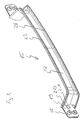
- Fig. 3 shows a perspective view of the inner part 15 of the handle 5, 6 with illuminant 18. It is ergonomically shaped and provided at its two ends in each case with a Anschraublasche 19.
- each two dome 20 for attachment of the inner part, with the aid of two screws, respectively, are provided on the housing 9.
- At the Anschraublaschen are also each a bore 21 for performing connection cables, not shown between the control device 7 and the above printed circuit board strip 17 is provided in the housing 9.
- a material thickening is provided in its longitudinal direction, which forms a fastening surface 22 for the printed circuit board strip 17.
- a portion of a clip connection 23, 24 are arranged on the outer sides of an upper and lower edge of the inner part 15 .
- a part of a clip connection 25 is arranged circumferentially.
- the inner part 15 is made of a translucent plastic material by injection molding. Due to the production of the translucent plastic material, with the exception of the screw-on lugs 19 and the fastening surface 22, all surfaces visible from the outside represent second light-emitting surfaces.
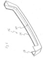
- Fig. 4 shows a perspective view of the outer part 16 of the handle 5, 6.
- the outer part is a perfect fit to the shape of the inner part 15 and also ergonomically shaped.
- the peripheral edges on which counterparts 26, 27, 28 are arranged to the clip connections 23, 24, 25, with the associated upper and lower edge of the inner part 15, as well as the mounting surfaces 22 are tuned to form a very narrow, uniform gap to meet hygienic requirements.
- the outer part 16 is made of the same translucent plastic material as the inner part 15 by injection molding. Thus, here also all surfaces visible from the outside represent the second light exit surfaces.
Description
Die Erfindung betrifft eine Operationsleuchte, die beleuchtete Handgriffe aufweist.The invention relates to a surgical light having illuminated handles.
Operationsleuchten werden an einer Raumdecke eines Operationssaals, einer Wand, oder als fahrbare Ausführungen an einem fahrbaren Ständer mit Hilfe eines so genannten Tragsystem befestigt. Das Tragsystem besteht üblicherweise aus einem ersten Ausleger, der um eine vertikale Achse schwenkbar ist und einem zweiten Ausleger, der horizontal schwenkbar und höhenverstellbar ist. Mit dem Tragsystem besteht die Möglichkeit, die Operationsleuchte an einer Stelle im Raum zu positionieren, von der aus es günstig ist, die Operationsstelle auszuleuchten.Operating lights are attached to a ceiling of an operating room, a wall, or as mobile versions of a mobile stand with the help of a so-called support system. The support system usually consists of a first arm, which is pivotable about a vertical axis and a second arm, which is horizontally pivotable and adjustable in height. With the support system, it is possible to position the operating light at a location in the room, from which it is beneficial to illuminate the surgical site.
Üblicherweise sind Operationsleuchten mit einem Griff, der im sterilen Bereich der Operationsleuchte angeordnet ist, und mit dem der sterile Operateur die Operationsleuchte positionieren kann, ausgerüstet.Usually, surgical lights are equipped with a handle which is arranged in the sterile area of the surgical light and with which the sterile surgeon can position the operating light.
Zur Positionierung der Operationsleuchte vor der Operation oder während der Operation durch unsteriles Operationspersonal sind die Operationsleuchten meistens mit weiteren Griffen am äußeren Umfang des Leuchtenkörpers ausgestattet.For positioning of the surgical light before surgery or during surgery by non-sterile surgical staff operating lights are usually equipped with additional handles on the outer circumference of the lamp body.
In den letzten Jahren vermehren sich die operativen Eingriffe in minimalinvasiver Operationstechnik. Diese Operationen werden ohne große Operationsöffnungen nur mit kleinen Öffnungen, durch die die Optik und die Instrumente eingeführt werden durchgeführt. Das Bild der minimalinvasiven Operationsstelle wird durch ein Kamerasystem auf Monitore, die auch an dem Tragsystem der Operationsleuchte angeordnet sein können, angezeigt. Bei dieser Operationstechnik ist zu Beginn der Operation helles Licht der Operationsleuchte erforderlich, um die Öffnung für die Operation zu schaffen. Während der minimalinvasiven Operation wird die Operationsleuchte ausgeschaltet und das Raumlicht im Operationssaal abgedunkelt, um für den Operateur die Sichtbedingungen auf die Monitore, auf die das Bild der Operationsstelle von dem Endoskop übertragen wird, zu verbessern. Dabei ergibt sich das Problem, dass die Position der Operationsleuchte nicht mehr einfach erkennbar ist, was zu Problemen beim Wiedereinschalten der Operationsleuchte führen kann, was zum Schließen der Wunden und zum Beenden der Operation erforderlich ist.In recent years, surgical interventions in minimally invasive surgical technique increase. These operations are performed without large surgical openings with only small openings, through the optics and instruments are introduced. The image of the minimally invasive surgical site is displayed by a camera system on monitors, which may also be arranged on the support system of the surgical light. In this surgical technique, bright light of the surgical light is required at the beginning of the operation to provide the opening for the operation. During the minimally invasive surgery, the surgical light is turned off and the room light in the operating room is dimmed to improve the operator's viewing conditions on the monitors to which the surgical site image is transmitted from the endoscope. This results in the problem that the position of the operating light is no longer easily recognizable, which can lead to problems when switching back the operating light, which is required to close the wounds and to complete the operation.
Die Patentanmeldung
In der Patentanmeldung
Es ist Aufgabe der Erfindung, dieses Problem zu lösen. Insbesondere ist es Aufgabe der Erfindung, eine Operationsleuchte mit Elementen bereitzustellen, die einfach und kostengünstig beleuchtbar sind, und die eine leichte Erkennung der Position und der Orientierung der Operationsleuchte ermöglichen.It is an object of the invention to solve this problem. In particular, it is an object of the invention to provide an operating light with elements that are easy and inexpensive to illuminate, and allow easy detection of the position and orientation of the surgical light.
Die Aufgabe wird mit den Kennzeichmenden Merkmalen des Anspruchs 1 gelöst. Weiterbildungen der Erfindung sind Gegenstand der Unteransprüche.The object is achieved with the characterizing features of claim 1. Further developments of the invention are the subject of the dependent claims.
Durch die Integration der Beleuchtungselemente in die Handgriffe ist die einfache, kostengünstige Möglichkeit gegeben, die Operationsleuchte ohne zusätzliche Verkleidungs- oder Halterungsbauteile mit Elementen zu versehen, aus denen Licht austritt. Die Lichtaustrittsfläche ist transluzent, d.h. lichtdurchlässig, ohne die Lichtquellen, wie bei einem transparenten Material sichtbar werden zu lassen.By integrating the lighting elements in the handles, the simple, cost-effective way is given to provide the operating light without additional cladding or support components with elements from which light emerges. The light exit surface is translucent, i. translucent, without the light sources, as in a transparent material to be visible.
In einer weiteren Ausgestaltung der Erfindung weist die transluzente Fläche eine strukturierte Oberfläche, d.h. eine erhabene Musterung der Oberfläche, wie sie z.B. bei sandgestrahlten, geriffelten oder kreuzgeriffelten Oberflächen erzeugt wird, auf. Dabei wird eine Oberfläche mit kugelförmigen Vertiefungen, dreiecksförmigen länglichen Erhöhungen, bzw. pyramidenförmigen Erhebungen erzeugt. Die Vertiefungen bzw. Erhöhungen bewegen sich dabei im Hundertstelmillimeter-Bereich. Somit tritt das Licht diffus aus den zweiten Lichtaustrittsflächen und man kann die Herkunft des Lichts, also das Leuchtmittel, nicht erkennen.In a further embodiment of the invention, the translucent surface has a textured surface, i. a raised pattern of the surface, as e.g. is produced in sandblasted, corrugated or kreuzgeriffelten surfaces on. In this case, a surface with spherical depressions, triangular elongated elevations, or pyramidal elevations is generated. The depressions or elevations thereby move in the hundredths of a millimeter range. Thus, the light diffused from the second light exit surfaces and you can not see the origin of the light, so the bulb.
Die Orientierung von Normalen, die an verschiedenen Orten auf der zweiten Lichtaustrittsfläche senkrecht stehen, in mindestens zwei verschiedenen Richtungen, d.h. die Ausrichtung von zwei verschiedenen Lichtaustrittsflächen unter einem bestimmten Raumwinkel, oder eine Krümmung von nur einer Lichtaustrittsfläche, ermöglicht das deutlichere Erkennen des Lichts aus verschiedenen Blickrichtungen.The orientation of normals perpendicular to different locations on the second light exit surface in at least two different directions, i. The alignment of two different light exit surfaces under a certain solid angle, or a curvature of only one light exit surface, allows the clearer recognition of the light from different directions.
Der Handgriff ist aus Gründen einer guten Erreichbarkeit an dem äußeren Umfang des Leuchtenkörpers angebracht, kann aber auch in einer alternativen Ausführungsform am Tragsystem angeordnet sein.The handle is attached for reasons of good accessibility to the outer periphery of the lamp body, but can also be arranged in an alternative embodiment of the support system.
In einer weiteren Ausgestaltung der Erfindung wird die Farbe des Lichts, das von dem Leuchtmittel ausgestrahlt wird, durch die Lichtaustrittsfläche nicht verändert. D.h. Licht, das durch ein weißes Leuchtmittel ausgestrahlt wird, bleibt auch nach dem Durchtritt durch die Lichtaustrittsfläche weiß.In a further embodiment of the invention, the color of the light emitted by the illuminant is not changed by the light exit surface. That Light that is emitted by a white light source remains white even after passing through the light exit surface.
Hingegen wird in einer alternativen Ausführungsform der Erfindung die Farbe des ausgestrahlten Lichts durch die Lichtaustrittsfläche verändert. Von dem Leuchtmittel abgegebenes weißes Licht wird durch die Lichtaustrittsfläche beispielsweise in blaues ausgestrahltes Licht verändert.On the other hand, in an alternative embodiment of the invention, the color of the emitted light is changed by the light exit surface. White light emitted by the luminous means is changed by the light exit surface, for example into blue emitted light.
Wird das Leuchtmittel so angeschlossen, dass eine Stromversorgung der Operationsleuchte angezeigt wird, so ist an der Operationsleuchte erkennbar, ob die Operationsleuchte durch einen externen Hauptschalter stromlos geschaltet wurde, oder ob sie sich in einem Standby-Modus befindet und direkt an der Operationsleuchte eingeschaltet werden kann.If the bulb is connected to indicate a power supply to the operating light, the operating light will indicate whether the operating light has been de-energized by an external main switch or if it is in standby mode and can be turned on directly to the operating light ,
In dem Fall, in dem die Operationsleuchte von verschiedenen Stromversorgungen, beispielsweise einerseits von einer normalen Stromversorgung aus einem konventionellen Versorgungsnetz, oder andererseits einer speziellen Stromversorgung mit einem batteriegepufferten Notstromaggregat, das innerhalb von kürzester Zeit einen Ausfall der normalen Stromversorgung kompensiert, versorgt wird, ist es wichtig die Art der Stromversorgung zu erkennen. Dabei ist das Leuchtmittel so angeschlossen, dass es bei der Versorgung durch die spezielle Stromversorgung leuchtet und diese somit angezeigt wird. Das Anzeigen kann beispielsweise durch ein Leuchten des Leuchtmittels oder durch Blinken des Leuchtmittels in einem bestimmten Rhythmus erfolgen.It is in the case where the operating light is supplied by various power supplies, for example, on the one hand from a normal power supply from a conventional power supply, or on the other hand a special power supply with a battery-backed emergency generator that compensates for failure of the normal power supply within a very short time important to recognize the type of power supply. In this case, the light source is connected so that it lights up when supplied by the special power supply and this is thus displayed. The display can be done for example by lighting the bulb or by flashing the bulb in a certain rhythm.
Alternativ zum Leuchten oder Blinken des Leuchtmittels wird in einer weiteren Ausführungsform die Farbe des ausgestrahlten Lichts bei der Versorgung durch die spezielle Stromversorgung geändert. So wird beispielsweise durch die externe Umschaltung der Versorgung auf die spezielle Stromversorgung ein Farbfilter zwischen das Leuchtmittel und die Lichtaustrittsfläche eingebracht.As an alternative to lighting or flashing of the luminous means, the color of the emitted light is changed in the supply by the special power supply in a further embodiment. For example, by the external switching of the supply to the special power supply, a color filter is introduced between the light source and the light exit surface.
Der Betrieb mit der Versorgung mit der speziellen Stromversorgung wird in einer Weiterbildung durch mindestens ein zweites, spezielles Leuchtmittel angezeigt, das der Handgriff aufweist. Das spezielle Leuchtmittel strahlt dann eine andere Farbe aus, als das Leuchtmittel, wodurch der Betrieb mit der speziellen Stromversorgung angezeigt wird.The operation with the supply of the special power supply is displayed in a development by at least a second, special light source, which has the handle. The special bulb then emits a different color than the bulb, indicating operation with the special power supply.
In einer anderen Ausführung ist ein drittes Leuchtmittel so angeschlossen, dass es einen bestimmten Betriebszustand, beispielsweise den Betrieb bei einer normgerechten Lichtstärkeverteilung im Leuchtfeld, anzeigt.In another embodiment, a third light source is connected so that it indicates a specific operating state, for example, the operation of a standard light intensity distribution in the light field.
In einer weiteren Ausführungsform hat ein Teil der zweiten Lichtaustrittsfläche einen refraktorartigen Aufbau. Dadurch wird das Licht von dem vierten Leuchtmittel innerhalb des Griffs so fokussiert, dass bei ausgeschalteten Leuchtmitteln in der ersten Lichtaustrittsfläche des Leuchtenkörpers das Operationsfeld für minimalinvasive Operationen beleuchtet wird.In a further embodiment, a part of the second light exit surface has a refractory structure. As a result, the light from the fourth illuminant within the handle is focused in such a way that, when the illuminants are switched off in the first light exit surface of the luminaire body, the operating field is illuminated for minimally invasive operations.
Dafür ist in einer alternativen Ausbildung ein weiteres viertes Leuchtmittel vorhanden, das Licht ausstrahlt, das durch den Refraktor fokussiert und ausgestrahlt wird.For this purpose, in an alternative embodiment, another fourth illuminant is present which emits light which is focused and emitted by the refractor.
Für spezielle Anwendung, beispielsweise für die Diagnostik, hat das Licht des vierten Leuchtmittels die Charakteristik, dass es nur Schwingungen in einem sehr engen Wellenlängenbereich aufweist. Beispielsweise wird in Kombination mit dem Fluorophor Fluorescein, das in das zu untersuchende Gewebe injiziert wird, ein Leuchtmittel verwendet, das eine Wellenlänge von 450 ± 5 Nanometer aufweist, wodurch das Fluorophor zum Strahlen angeregt wird. So kann über einen Filter, der nur das von dem Fluorphor ausgestrahlte Licht passieren lässt, eine Gewebeerkennung durchgeführt werden.For special application, for example for diagnostics, the light of the fourth light source has the characteristic that it only has vibrations in a very narrow wavelength range. For example, in combination with the fluorophore fluorescein, which is injected into the tissue to be examined, a light source having a wavelength of 450 ± 5 nanometers is used, whereby the fluorophore is excited to radiate. Thus, a tissue recognition can be performed via a filter which allows only the light emitted by the fluorophore to pass through.
Die Erfindung wird anhand eines Ausführungsbeispiels unter Bezugnahme auf die beigefügten Zeichnungen erläutert.
- Fig. 1
- ist eine perspektivische Ansicht eines Ausführungsbei- spiels der erfindungsgemäßen Operationsleuchte.
- Fig. 2
- zeigt einen Teil einer geschnittenen Seitenansicht ei- nes Leuchtenkörpers mit einem Handgriff.
- Fig. 3
- zeigt eine perspektivische Ansicht eines Innenteils eines Handgriffs mit Leuchtmittel.
- Fig. 4
- zeigt eine perspektivische Ansicht eines Außenteils eines Handgriffs.
- Fig. 1
- is a perspective view of an embodiment of the surgical light according to the invention.
- Fig. 2
- shows a part of a sectional side view of a lamp body with a handle.
- Fig. 3
- shows a perspective view of an inner part of a handle with bulbs.
- Fig. 4
- shows a perspective view of an outer part of a handle.
Zum unsterilen Positionieren des Leuchtenkörpers 4 sind an den beiden Hälften des Leuchtenkörpers 4 je ein Handgriff 5, 6 angebracht. Die beiden Hälften des Leuchtenkörpers 4 sind drehfest miteinander verbunden, so dass sich beim Verschwenken der einen Hälfte die andere Hälfte mit bewegt, um die Lichtaustrittsflächen immer in einer Ebene zu halten.For unsterile positioning of the
Innerhalb des Leuchtenkörpers 4 ist eine später beschriebene Steuerungsvorrichtung 7 angeordnet, um lange Kabelverbindungen zu vermeiden. Die Steuerungsvorrichtung muss jedoch nicht zwingend in dem Leuchtenkörper 4 angeordnet sein, sondern kann auch, um den Leuchtenköper möglichst klein und strömungsgünstig zu gestalten, in einem separaten Gehäuse, das am Leuchtenkörper 4 oder an der Aufhängevorrichtung 3 angeordnet ist, untergebracht sein. Alternativ besteht auch die Möglichkeit, dass sich die Steuerungsvorrichtung 7 in einer nicht gezeigten externen Bedieneinheit befindet, die sich in einer Medizinischen Versorgungseinheit oder in/an einer Wand befindet.Within the
An der Außenseite des Leuchtenkörpers 4 ist eine Bedienvorrichtung 8 mit Schalt- und Einstellelementen angeordnet. Die Bedienvorrichtung 8 kann sich aber auch in einem separaten Gehäuse befinden, das sich beispielsweise am Leuchtenkörper 4, an der Aufhängevorrichtung 3 oder in einer Medizinischen Versorgungseinheit oder in/an einer Wand befindet.On the outside of the
Die Abdeckscheibe 12 ist an dem Gehäuse 9 befestigt. Die Lichtstrahlen sind auf ein Operationsfeld, das sich in einem bestimmten Abstand befindet, gerichtet und bilden dort ein Leuchtfeld als einen Bereich, der durch die Lichtstrahlen beleuchtet wird.The
Der Handgriff 6 besteht aus zwei Teilen, einem Innenteil 15 und einem Außenteil 16. Das Innenteil 15 ist seitlich durch vier hier nicht gezeigte Schrauben mit dem Gehäuse 9 verbunden. Das Außenteil 16 ist über eine Clipverbindung mit dem Innenteil 15 verbunden.The
An dem Innenteil 15 ist mit Hilfe eines Klebebands ein Leiterplattenstreifen 17 befestigt. Auf dem Leiterplattenstreifen 17 sind zehn Leuchtmittel 18, hier LEDs, befestigt und elektrisch verbunden. Der Leiterplattenstreifen wird über nicht gezeigte Kabel versorgt.On the
In dem Gehäuse 9 des Leuchtenkörpers 4 befindet sich die Steuerungsvorrichtung 7. Die Steuerungsvorrichtung 7 weist Mittel zum Dimmen und Ein- und Ausschalten der Leuchtmittel 10, wie z.B. Stromregler, Mittel zum Übertragen von Schalt- und Einstellinformationen der Schalt- und Einstellelemente der Bedienvorrichtung 8, einen Speicherbereich zum Abspeichern von Betriebsparametern und eine CPU, die aus den Schalt- und Einstellinformationen, an Hand der abgespeicherten Betriebsparameter, die erforderlichen Einstellungen für die Mittel zum Dimmen und Ein- und Ausschalten der Leuchtmittel 10 berechnet oder bestimmt, auf.In the housing 9 of the
Die Steuerungsvorrichtung 7 ist mit einer nicht gezeigten Stromversorgungsvorrichtung, den Leuchtmitteln 18 und den Leuchtmitteln 10, sowie der Bedienvorrichtung 8 mit einem Element zum Ein-/Ausschalten verbunden.The
An der Bedienvorrichtung 8 (
- ein Element zum Ein-/Ausschalten,
- ein Element zur Abstandseinstellung und
- ein Element zur Helligkeitseinstellung
- an element for switching on / off,
- a distance adjustment element and
- a brightness adjustment item
In einer alternativen Ausführungsform ist die Bedienvorrichtung beleuchtet. Hierbei besteht optional die Möglichkeit, die gesamte Bedienvorrichtung, die angezeigten Symbole und die Betätigungselemente alternativ oder gemeinsam zu beleuchten.In an alternative embodiment, the operating device is illuminated. In this case, it is optionally possible to illuminate the entire operating device, the symbols displayed and the actuating elements alternatively or jointly.
Das Element zum Ein-/Ausschalten schaltet die Operationsleuchte 1 von einem Standby-Modus, in dem die Leuchtmittel 10 nicht leuchten, in einen Betriebsmodus und zurück. Im Betriebsmodus werden die Leuchtmittel 10 entsprechend der Einstellungen der Einstellelemente an der Bedienvorrichtung 8 betrieben. Zum vollständigen Ausschalten durch Abschalten der Stromversorgung ist ein nicht gezeigter externer Hauptschalter vorgesehen. Bei einem Abschalten der Stromversorgung erlöschen die Leuchtmittel 18. Ansonsten leuchten die Leuchtmittel 18 sowohl im Standby-Modus als auch im Betriebsmodus der Operationsleuchte 1.The on / off switching element switches the operation light 1 from a standby mode in which the
Auf der Innenseite des Innenteils 15 ist in seiner Längsrichtung eine Materialverdickung vorgesehen, die eine Befestigungsfläche 22 für den Leiterplattenstreifen 17 bildet. An den Außenseiten eines oberen und unteren Rands des Innenteils 15 sind jeweils umlaufend von der Befestigungsfläche 22 bis zur gegenüberliegenden Befestigungsfläche ein Teil einer Clipverbindung 23, 24 angeordnet. Auch an den beiden Anschraublaschen 19 ist umlaufend ein Teil einer Clipverbindung 25 angeordnet. Das Innenteil 15 ist aus einem transluzentem Kunststoffmaterial im Spritzgussverfahren hergestellt. Durch die Herstellung aus dem transluzentem Kunststoffmaterial, stellen, mit Ausnahme der Anschraublaschen 19 und der Befestigungsfläche 22, alle von außen sichtbaren Flächen zweite Lichtaustrittsflächen dar.On the inside of the
Somit stellen auch hier alle von außen sichtbaren Flächen die zweiten Lichtaustrittsflächen dar.
Thus, here also all surfaces visible from the outside represent the second light exit surfaces.
Claims (15)
- Operating lamp having a carrying system (2), a lamp body (4) with a first light emerging face (13), and at least one handle (5, 6) having at least one illuminant (18), wherein the handle (5, 6) at least partially comprises a second light emerging face and the second light emerging face is translucent, characterized in that approximately the entire handle (5, 6) comprises the second light emerging face.
- Operating lamp according to claim 1, characterized in that the second light emerging face comprises a structured surface and the light of the illuminant (18) diffusely emerges.
- Operating lamp according to any of claims 1 or 2, characterized in that the second light emerging face is designed such that normals being perpendicular on the second light emerging face at different locations are oriented in at least two directions.
- Operating lamp according to any of the preceding claims, characterized in that the handle (5, 6) is fixed at the outer circumference of the housing (9) of the lamp body (4).
- Operating lamp according to any of the preceding claims, characterized in that second light emerging face does not modify the colour of the light emitted by the illuminant (18).
- Operating lamp according to any of the preceding claims, characterized in that the second light emerging face modifies the colour of the light emitted by the illuminant (18).
- Operating lamp according to any of the preceding claims, characterized in that the illuminant is connected in such a way that an electricity supply of the operating lamp is indicated.
- Operating lamp according to any of the preceding claims, characterized in that the operating lamp is alternatively supplied by a normal and by a special electricity supply and an illuminant is connected in such a way that an operation with the special electricity supply is indicated.
- Operating lamp according to claim 8, characterized in that the emitted light has a colour which is different during operation with the special electricity supply than during operation with the normal electricity supply.
- Operating lamp according to any of claims 1 to 7, characterized in that the operating lamp is alternatively supplied by a normal electricity supply and by a special electricity supply and the handle (5, 6) comprises at least one second specific illuminant indicating an operation with the special electricity supply.
- Operating lamp according to claim 10, characterized in that the light emitted by the specific illuminant has a colour which is different from the colour of the light emitted by the illuminant (18).
- Operating lamp according to any of the preceding claims, characterized in that a third illuminant is connected in such a way that a particular operating condition of the operating lamp (1), preferably a standardized light distribution in the illuminated field, is indicated.
- Operating lamp according to any of the preceding claims, characterized in that a portion of the second light emerging face has a refractor-like structure.
- Operating lamp according to claim 13, characterized in that the light through the portion with the refractor-like structure is emitted by at least a fourth illuminant.
- Operating lamp according to claim 14, characterized in that the light of the fourth illuminant has a narrow-banded wavelength, preferably 450 ± 5 nanometre.
Priority Applications (5)
| Application Number | Priority Date | Filing Date | Title |
|---|---|---|---|
| DE202008017921U DE202008017921U1 (en) | 2008-06-20 | 2008-06-20 | Operating light with illuminated handles |
| EP08011295A EP2136127B1 (en) | 2008-06-20 | 2008-06-20 | Operating light with illuminated handles |
| PL08011295T PL2136127T3 (en) | 2008-06-20 | 2008-06-20 | Operating light with illuminated handles |
| DE502008001530T DE502008001530D1 (en) | 2008-06-20 | 2008-06-20 | Operating light with illuminated handles |
| US12/487,081 US8308333B2 (en) | 2008-06-20 | 2009-06-18 | Surgical lamp with illuminated handles |
Applications Claiming Priority (1)
| Application Number | Priority Date | Filing Date | Title |
|---|---|---|---|
| EP08011295A EP2136127B1 (en) | 2008-06-20 | 2008-06-20 | Operating light with illuminated handles |
Publications (2)
| Publication Number | Publication Date |
|---|---|
| EP2136127A1 EP2136127A1 (en) | 2009-12-23 |
| EP2136127B1 true EP2136127B1 (en) | 2010-10-13 |
Family
ID=40002926
Family Applications (1)
| Application Number | Title | Priority Date | Filing Date |
|---|---|---|---|
| EP08011295A Active EP2136127B1 (en) | 2008-06-20 | 2008-06-20 | Operating light with illuminated handles |
Country Status (4)
| Country | Link |
|---|---|
| US (1) | US8308333B2 (en) |
| EP (1) | EP2136127B1 (en) |
| DE (2) | DE502008001530D1 (en) |
| PL (1) | PL2136127T3 (en) |
Families Citing this family (8)
| Publication number | Priority date | Publication date | Assignee | Title |
|---|---|---|---|---|
| DE202008017923U1 (en) * | 2008-06-20 | 2010-11-04 | Trumpf Medizin Systeme Gmbh + Co. Kg | Operating light with suspension device |
| US9107792B2 (en) | 2012-09-07 | 2015-08-18 | Allen Medical Systems, Inc. | Carriage for a surgical boot of a hip distractor |
| US9730851B2 (en) | 2012-09-07 | 2017-08-15 | Allen Medical Systems, Inc. | Surgical support system |
| US10603132B2 (en) | 2016-11-01 | 2020-03-31 | American Sterilizer Company | Lighthead identification system for lighthead control |
| AU2021214378B2 (en) | 2020-01-31 | 2024-02-29 | American Sterilizer Company | Lighting assembly and light head including same |
| CN113606520B (en) * | 2021-08-04 | 2023-06-27 | 显微智能科技(湖南)有限公司 | Coating operating lamp capable of adjusting type of cut-off film and adjusting method |
| USD1015622S1 (en) | 2021-09-16 | 2024-02-20 | Trumpf Medizin Systeme Gmbh + Co. Kg | Suspension apparatus for a medical lamp |
| USD1014832S1 (en) | 2021-09-16 | 2024-02-13 | Trumpf Medizin Systeme Gmbh + Co. Kg | Support arm for a suspension apparatus for a medical lamp |
Family Cites Families (14)
| Publication number | Priority date | Publication date | Assignee | Title |
|---|---|---|---|---|
| US4605124A (en) * | 1983-08-09 | 1986-08-12 | Devon Industries, Inc. | Disposable cover for surgical light handle |
| US5023515A (en) * | 1990-03-16 | 1991-06-11 | American Sterilizer Company | Redundant lamp control circuit |
| US5142736A (en) * | 1990-09-20 | 1992-09-01 | Pinnacle Products, Inc. | Disposable sleeve for covering handles of dentist's lights and method of using the same |
| US5562344A (en) | 1994-02-10 | 1996-10-08 | Mdt Corporation | Handle for dental light |
| US6739744B2 (en) * | 1997-07-02 | 2004-05-25 | Lumitex, Inc. | Light delivery systems and applications thereof |
| US6132062A (en) | 1998-03-27 | 2000-10-17 | Hill-Rom, Inc. | Task light for a surgical light apparatus |
| US6715904B2 (en) * | 2001-07-19 | 2004-04-06 | Michael L. Naughton | Laser light handle |
| AU2003219860B2 (en) * | 2002-02-25 | 2005-12-01 | American Sterilizer Company | Ergonomic controls in a surgical lighting system |
| FI115600B (en) * | 2003-06-27 | 2005-05-31 | Planmeca Oy | LED surgical lighting apparatus |
| EP1568934B1 (en) * | 2004-02-28 | 2012-05-30 | TRUMPF Medizin Systeme GmbH + Co. KG | Surgical light |
| EP1754121A4 (en) * | 2004-03-15 | 2014-02-12 | Philips Solid State Lighting | Methods and systems for providing lighting systems |
| US7207694B1 (en) * | 2004-08-20 | 2007-04-24 | Boyd Industries, Inc. | Light emitting diode operating and examination light system |
| DE102005036275A1 (en) * | 2005-08-02 | 2007-02-08 | Berchtold Holding Gmbh | surgical light |
| US7922348B2 (en) | 2006-01-23 | 2011-04-12 | Razeto Design'n Innovation Srl | Luminous handle for doors, furnishings, means of transport or the like |
-
2008
- 2008-06-20 DE DE502008001530T patent/DE502008001530D1/en active Active
- 2008-06-20 PL PL08011295T patent/PL2136127T3/en unknown
- 2008-06-20 DE DE202008017921U patent/DE202008017921U1/en not_active Expired - Lifetime
- 2008-06-20 EP EP08011295A patent/EP2136127B1/en active Active
-
2009
- 2009-06-18 US US12/487,081 patent/US8308333B2/en active Active
Also Published As
| Publication number | Publication date |
|---|---|
| DE502008001530D1 (en) | 2010-11-25 |
| PL2136127T3 (en) | 2011-04-29 |
| DE202008017921U1 (en) | 2010-11-04 |
| EP2136127A1 (en) | 2009-12-23 |
| US20090316394A1 (en) | 2009-12-24 |
| US8308333B2 (en) | 2012-11-13 |
Similar Documents
| Publication | Publication Date | Title |
|---|---|---|
| EP2136127B1 (en) | Operating light with illuminated handles | |
| EP1378771B1 (en) | Interior lighting | |
| DE10034594B4 (en) | Dental treatment light | |
| EP2136129B1 (en) | Operating light with distance-dependant brightness control | |
| DE69838386T2 (en) | LIGHTING SYSTEM AND ITS APPLICATION | |
| EP1568934A1 (en) | Surgical light | |
| DE102010037920A1 (en) | lighting | |
| DE19942177A1 (en) | Lamp with electrically-controlled light source provided by semiconductor element emitting visible electromagnetic radiation controlled for providing variable light intensity and/or color spectrum | |
| DE102010014839B4 (en) | recessed light | |
| EP2578928B1 (en) | Lighting device with natural and artificial light | |
| DE102007058173A1 (en) | Lamp for use in e.g. private area, has light unit arranged in stand part and light from light unit coupled to light shaft and light plate in stand part, where light shaft and light plate are transparent and made of glass or acrylic glass | |
| DE102008017271B4 (en) | Luminaire with two light sources in a recess of an at least partially photoconductive support, use of this lamp as a pendant, wall or floor lamp and lighting device for such a lamp | |
| DE202005016891U1 (en) | Supply device e.g. for provision of technical gases in hospital wards, has molded body to allow direct or indirect attachment on wall | |
| DE102010028416A1 (en) | LED module with lens for generating a non-rotationally symmetrical light distribution | |
| DE102014207640A1 (en) | Arrangement for emitting light for arrangement on a luminaire housing | |
| EP2060847A1 (en) | Operating light | |
| EP1536179B1 (en) | Surgical light apparatus for use in endoscopic operations | |
| EP2360420B1 (en) | Modular lamp system for light emitting diodes | |
| DE102006037896A1 (en) | lamp | |
| DE102005000908A1 (en) | Retractor for surgical purpose, has lighting device with white semiconductor light emitting diode, and switchable and/or dimmable ballast/switching power supply-electronic effect switching and/or control of diode | |
| EP2636948A1 (en) | LED lamp and method for operating such a lamp | |
| EP2498241A2 (en) | Emergency light with a lighting means for indicating the charge level of batteries | |
| DE202007006347U1 (en) | Lighting mechanism for attachment to e.g. human body, post has base comprised of flexible line plate on which light emitting diodes (LEDs) are arranged | |
| AT517745A2 (en) | Combined lighting and ventilation device | |
| WO2007033864A1 (en) | Optical display for producing an optical signal |
Legal Events
| Date | Code | Title | Description |
|---|---|---|---|
| PUAI | Public reference made under article 153(3) epc to a published international application that has entered the european phase |
Free format text: ORIGINAL CODE: 0009012 |
|
| 17P | Request for examination filed |
Effective date: 20090324 |
|
| AK | Designated contracting states |
Kind code of ref document: A1 Designated state(s): AT BE BG CH CY CZ DE DK EE ES FI FR GB GR HR HU IE IS IT LI LT LU LV MC MT NL NO PL PT RO SE SI SK TR |
|
| AX | Request for extension of the european patent |
Extension state: AL BA MK RS |
|
| GRAP | Despatch of communication of intention to grant a patent |
Free format text: ORIGINAL CODE: EPIDOSNIGR1 |
|
| GRAS | Grant fee paid |
Free format text: ORIGINAL CODE: EPIDOSNIGR3 |
|
| AKX | Designation fees paid |
Designated state(s): CH DE FR GB IT LI PL |
|
| GRAA | (expected) grant |
Free format text: ORIGINAL CODE: 0009210 |
|
| AK | Designated contracting states |
Kind code of ref document: B1 Designated state(s): CH DE FR GB IT LI PL |
|
| REG | Reference to a national code |
Ref country code: GB Ref legal event code: FG4D Free format text: NOT ENGLISH |
|
| REG | Reference to a national code |
Ref country code: CH Ref legal event code: EP |
|
| REG | Reference to a national code |
Ref country code: CH Ref legal event code: NV Representative=s name: NOVAGRAAF INTERNATIONAL SA |
|
| REF | Corresponds to: |
Ref document number: 502008001530 Country of ref document: DE Date of ref document: 20101125 Kind code of ref document: P |
|
| REG | Reference to a national code |
Ref country code: PL Ref legal event code: T3 |
|
| REG | Reference to a national code |
Ref country code: CH Ref legal event code: PFA Owner name: TRUMPF MEDIZIN SYSTEME GMBH + CO. KG Free format text: TRUMPF MEDIZIN SYSTEME GMBH + CO. KG#BENZSTRASSE 26#82178 PUCHHEIM (DE) -TRANSFER TO- TRUMPF MEDIZIN SYSTEME GMBH + CO. KG#BENZSTRASSE 26#82178 PUCHHEIM (DE) |
|
| PLBI | Opposition filed |
Free format text: ORIGINAL CODE: 0009260 |
|
| PLAX | Notice of opposition and request to file observation + time limit sent |
Free format text: ORIGINAL CODE: EPIDOSNOBS2 |
|
| 26 | Opposition filed |
Opponent name: BERCHTOLD HOLDING GMBH Effective date: 20110711 |
|
| REG | Reference to a national code |
Ref country code: DE Ref legal event code: R026 Ref document number: 502008001530 Country of ref document: DE Effective date: 20110711 |
|
| PLBB | Reply of patent proprietor to notice(s) of opposition received |
Free format text: ORIGINAL CODE: EPIDOSNOBS3 |
|
| PLCK | Communication despatched that opposition was rejected |
Free format text: ORIGINAL CODE: EPIDOSNREJ1 |
|
| PLBN | Opposition rejected |
Free format text: ORIGINAL CODE: 0009273 |
|
| STAA | Information on the status of an ep patent application or granted ep patent |
Free format text: STATUS: OPPOSITION REJECTED |
|
| 27O | Opposition rejected |
Effective date: 20131108 |
|
| REG | Reference to a national code |
Ref country code: DE Ref legal event code: R100 Ref document number: 502008001530 Country of ref document: DE Effective date: 20131108 |
|
| REG | Reference to a national code |
Ref country code: FR Ref legal event code: PLFP Year of fee payment: 9 |
|
| PGFP | Annual fee paid to national office [announced via postgrant information from national office to epo] |
Ref country code: CH Payment date: 20160613 Year of fee payment: 9 |
|
| PGFP | Annual fee paid to national office [announced via postgrant information from national office to epo] |
Ref country code: IT Payment date: 20160621 Year of fee payment: 9 |
|
| REG | Reference to a national code |
Ref country code: FR Ref legal event code: PLFP Year of fee payment: 10 |
|
| REG | Reference to a national code |
Ref country code: CH Ref legal event code: PL |
|
| PG25 | Lapsed in a contracting state [announced via postgrant information from national office to epo] |
Ref country code: LI Free format text: LAPSE BECAUSE OF NON-PAYMENT OF DUE FEES Effective date: 20170630 Ref country code: CH Free format text: LAPSE BECAUSE OF NON-PAYMENT OF DUE FEES Effective date: 20170630 |
|
| REG | Reference to a national code |
Ref country code: FR Ref legal event code: PLFP Year of fee payment: 11 |
|
| PG25 | Lapsed in a contracting state [announced via postgrant information from national office to epo] |
Ref country code: IT Free format text: LAPSE BECAUSE OF NON-PAYMENT OF DUE FEES Effective date: 20170620 |
|
| PGFP | Annual fee paid to national office [announced via postgrant information from national office to epo] |
Ref country code: AT Payment date: 20180621 Year of fee payment: 12 |
|
| PG25 | Lapsed in a contracting state [announced via postgrant information from national office to epo] |
Ref country code: PL Free format text: LAPSE BECAUSE OF NON-PAYMENT OF DUE FEES Effective date: 20190620 |
|
| PGFP | Annual fee paid to national office [announced via postgrant information from national office to epo] |
Ref country code: FR Payment date: 20230524 Year of fee payment: 16 Ref country code: DE Payment date: 20230523 Year of fee payment: 16 |
|
| PGFP | Annual fee paid to national office [announced via postgrant information from national office to epo] |
Ref country code: GB Payment date: 20230523 Year of fee payment: 16 |