EP2136128B1 - Operating light - Google Patents
Operating light Download PDFInfo
- Publication number
- EP2136128B1 EP2136128B1 EP08011296A EP08011296A EP2136128B1 EP 2136128 B1 EP2136128 B1 EP 2136128B1 EP 08011296 A EP08011296 A EP 08011296A EP 08011296 A EP08011296 A EP 08011296A EP 2136128 B1 EP2136128 B1 EP 2136128B1
- Authority
- EP
- European Patent Office
- Prior art keywords
- light
- distance
- illuminants
- surgical lamp
- lamp according
- Prior art date
- Legal status (The legal status is an assumption and is not a legal conclusion. Google has not performed a legal analysis and makes no representation as to the accuracy of the status listed.)
- Revoked
Links
Images


Classifications
-
- A—HUMAN NECESSITIES
- A61—MEDICAL OR VETERINARY SCIENCE; HYGIENE
- A61B—DIAGNOSIS; SURGERY; IDENTIFICATION
- A61B90/00—Instruments, implements or accessories specially adapted for surgery or diagnosis and not covered by any of the groups A61B1/00 - A61B50/00, e.g. for luxation treatment or for protecting wound edges
- A61B90/30—Devices for illuminating a surgical field, the devices having an interrelation with other surgical devices or with a surgical procedure
- A61B90/35—Supports therefor
-
- F—MECHANICAL ENGINEERING; LIGHTING; HEATING; WEAPONS; BLASTING
- F21—LIGHTING
- F21S—NON-PORTABLE LIGHTING DEVICES; SYSTEMS THEREOF; VEHICLE LIGHTING DEVICES SPECIALLY ADAPTED FOR VEHICLE EXTERIORS
- F21S8/00—Lighting devices intended for fixed installation
-
- A—HUMAN NECESSITIES
- A61—MEDICAL OR VETERINARY SCIENCE; HYGIENE
- A61B—DIAGNOSIS; SURGERY; IDENTIFICATION
- A61B50/00—Containers, covers, furniture or holders specially adapted for surgical or diagnostic appliances or instruments, e.g. sterile covers
- A61B50/20—Holders specially adapted for surgical or diagnostic appliances or instruments
- A61B50/24—Stands
- A61B50/28—Stands suspended from the ceiling
-
- A—HUMAN NECESSITIES
- A61—MEDICAL OR VETERINARY SCIENCE; HYGIENE
- A61B—DIAGNOSIS; SURGERY; IDENTIFICATION
- A61B90/00—Instruments, implements or accessories specially adapted for surgery or diagnosis and not covered by any of the groups A61B1/00 - A61B50/00, e.g. for luxation treatment or for protecting wound edges
- A61B90/30—Devices for illuminating a surgical field, the devices having an interrelation with other surgical devices or with a surgical procedure
-
- F—MECHANICAL ENGINEERING; LIGHTING; HEATING; WEAPONS; BLASTING
- F21—LIGHTING
- F21V—FUNCTIONAL FEATURES OR DETAILS OF LIGHTING DEVICES OR SYSTEMS THEREOF; STRUCTURAL COMBINATIONS OF LIGHTING DEVICES WITH OTHER ARTICLES, NOT OTHERWISE PROVIDED FOR
- F21V14/00—Controlling the distribution of the light emitted by adjustment of elements
-
- F—MECHANICAL ENGINEERING; LIGHTING; HEATING; WEAPONS; BLASTING
- F21—LIGHTING
- F21V—FUNCTIONAL FEATURES OR DETAILS OF LIGHTING DEVICES OR SYSTEMS THEREOF; STRUCTURAL COMBINATIONS OF LIGHTING DEVICES WITH OTHER ARTICLES, NOT OTHERWISE PROVIDED FOR
- F21V23/00—Arrangement of electric circuit elements in or on lighting devices
- F21V23/003—Arrangement of electric circuit elements in or on lighting devices the elements being electronics drivers or controllers for operating the light source, e.g. for a LED array
-
- F—MECHANICAL ENGINEERING; LIGHTING; HEATING; WEAPONS; BLASTING
- F21—LIGHTING
- F21V—FUNCTIONAL FEATURES OR DETAILS OF LIGHTING DEVICES OR SYSTEMS THEREOF; STRUCTURAL COMBINATIONS OF LIGHTING DEVICES WITH OTHER ARTICLES, NOT OTHERWISE PROVIDED FOR
- F21V23/00—Arrangement of electric circuit elements in or on lighting devices
- F21V23/04—Arrangement of electric circuit elements in or on lighting devices the elements being switches
- F21V23/0442—Arrangement of electric circuit elements in or on lighting devices the elements being switches activated by means of a sensor, e.g. motion or photodetectors
- F21V23/0464—Arrangement of electric circuit elements in or on lighting devices the elements being switches activated by means of a sensor, e.g. motion or photodetectors the sensor sensing the level of ambient illumination, e.g. dawn or dusk sensors
-
- F—MECHANICAL ENGINEERING; LIGHTING; HEATING; WEAPONS; BLASTING
- F21—LIGHTING
- F21V—FUNCTIONAL FEATURES OR DETAILS OF LIGHTING DEVICES OR SYSTEMS THEREOF; STRUCTURAL COMBINATIONS OF LIGHTING DEVICES WITH OTHER ARTICLES, NOT OTHERWISE PROVIDED FOR
- F21V23/00—Arrangement of electric circuit elements in or on lighting devices
- F21V23/04—Arrangement of electric circuit elements in or on lighting devices the elements being switches
- F21V23/0442—Arrangement of electric circuit elements in or on lighting devices the elements being switches activated by means of a sensor, e.g. motion or photodetectors
- F21V23/0471—Arrangement of electric circuit elements in or on lighting devices the elements being switches activated by means of a sensor, e.g. motion or photodetectors the sensor detecting the proximity, the presence or the movement of an object or a person
-
- F—MECHANICAL ENGINEERING; LIGHTING; HEATING; WEAPONS; BLASTING
- F21—LIGHTING
- F21S—NON-PORTABLE LIGHTING DEVICES; SYSTEMS THEREOF; VEHICLE LIGHTING DEVICES SPECIALLY ADAPTED FOR VEHICLE EXTERIORS
- F21S2/00—Systems of lighting devices, not provided for in main groups F21S4/00 - F21S10/00 or F21S19/00, e.g. of modular construction
- F21S2/005—Systems of lighting devices, not provided for in main groups F21S4/00 - F21S10/00 or F21S19/00, e.g. of modular construction of modular construction
-
- F—MECHANICAL ENGINEERING; LIGHTING; HEATING; WEAPONS; BLASTING
- F21—LIGHTING
- F21V—FUNCTIONAL FEATURES OR DETAILS OF LIGHTING DEVICES OR SYSTEMS THEREOF; STRUCTURAL COMBINATIONS OF LIGHTING DEVICES WITH OTHER ARTICLES, NOT OTHERWISE PROVIDED FOR
- F21V19/00—Fastening of light sources or lamp holders
- F21V19/001—Fastening of light sources or lamp holders the light sources being semiconductors devices, e.g. LEDs
- F21V19/003—Fastening of light source holders, e.g. of circuit boards or substrates holding light sources
-
- F—MECHANICAL ENGINEERING; LIGHTING; HEATING; WEAPONS; BLASTING
- F21—LIGHTING
- F21V—FUNCTIONAL FEATURES OR DETAILS OF LIGHTING DEVICES OR SYSTEMS THEREOF; STRUCTURAL COMBINATIONS OF LIGHTING DEVICES WITH OTHER ARTICLES, NOT OTHERWISE PROVIDED FOR
- F21V7/00—Reflectors for light sources
- F21V7/0091—Reflectors for light sources using total internal reflection
-
- F—MECHANICAL ENGINEERING; LIGHTING; HEATING; WEAPONS; BLASTING
- F21—LIGHTING
- F21W—INDEXING SCHEME ASSOCIATED WITH SUBCLASSES F21K, F21L, F21S and F21V, RELATING TO USES OR APPLICATIONS OF LIGHTING DEVICES OR SYSTEMS
- F21W2131/00—Use or application of lighting devices or systems not provided for in codes F21W2102/00-F21W2121/00
- F21W2131/20—Lighting for medical use
- F21W2131/205—Lighting for medical use for operating theatres
-
- F—MECHANICAL ENGINEERING; LIGHTING; HEATING; WEAPONS; BLASTING
- F21—LIGHTING
- F21Y—INDEXING SCHEME ASSOCIATED WITH SUBCLASSES F21K, F21L, F21S and F21V, RELATING TO THE FORM OR THE KIND OF THE LIGHT SOURCES OR OF THE COLOUR OF THE LIGHT EMITTED
- F21Y2115/00—Light-generating elements of semiconductor light sources
- F21Y2115/10—Light-emitting diodes [LED]
Definitions
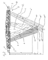
- Fig. 1 shows a perspective view of an embodiment of the surgical lamp according to the invention 1.
- the surgical light 1 comprises a support system 2, a suspension device 3 and a lamp body 4.
- the support system 2 is attached to a ceiling, a wall or a mobile stand.
- the lamp body 4 can be positioned within the radius of action in any spatial position and orientation.
- a light exit opening is arranged on almost the entire surface, which is directed in operation to a surgical field which is located at a certain distance.
- each a handle 5, 6 attached to the two halves of the lamp body 4.
- the two halves of the lamp body 4 are rotatably connected to each other, so that when pivoting the one half, the other half moves with to keep the light exit surfaces always in a plane.
- control device 7 is arranged within the lamp body 4, a control device 7 is arranged.
- the control device 7 does not necessarily have to be arranged in the lamp body 4, but can also be accommodated in a separate housing which is arranged on the lamp body 4 or on the suspension device 3.
- the control device 7 is located in an external operating unit, not shown, which is located in a medical supply unit or in / on a wall.
- an operating device 8 is arranged on the outside of the lamp body 4, on the suspension device 3 or in a medical supply unit or in / on a wall.
- Fig. 2 is a sectional view of a lamp body 4, in which a plurality of lighting means 9 is provided.
- the lamp body 4 has a central axis 12 which is perpendicular to a plane in which the lighting means 9 are arranged.
- the lighting means 9 are arranged annularly or in accordance with the shape of the lamp body 4.
- the bulbs 9 with the refractors 10 are arranged inclined, so that the axes a, a ', b, c of the light beam I, I', II, III intersect the central axis 12 in each case at an intersection 13, 13 ', 13 ".
- the generation of the luminous field 11 is described by way of example, the generation of the further luminous fields 11 ', 11 "takes place analogously.
- the point of intersection 13 is the point of intersection of the two axes I, I 'with the central axis 12, that is to say a focal point, so that the two luminous fields coincide and together form the luminous field 11.
- the light-emitting panel 11 has a specific diameter D and a defined distribution of the luminous intensity over the diameter of the luminous field, which is predetermined by the norm.
- Fig. 2 only two light sources 9 are shown, which form the light field 11.
- the light field 11 is formed by a bevy of light beam I, I ', which are emitted by the bulbs 9, which are evenly distributed over the light exit surface and their axes a, a' of the light beam I, I 'intersect at the intersection 13.
- the lighting means 9 are evenly distributed in the plane to an obstacle, which is introduced between the lamp body 4 and the surgical field and thereby interrupts a light beam, which has a shadowing result, to undercut and thus prevent or mitigate the shadowing.
- the lighting means 9 are formed in this embodiment by LEDs, but can also be designed as halogen lamps or gas discharge lamps, possibly with color filters.
- the control device 7 is connected to the lighting means 9, which are controlled in groups.
- a group is formed from a plurality of lighting means 9, which are driven with the same performance parameters.
- the individual groups each consist only of light sources 9 whose light beams I, I ', II, II have the same intersection 13, 13', 13 "with the central axis 12. However, several groups are possible whose light beams I, I ', II, III of the lamps 9 are directed to the same intersection 13, 13 ', 13 ".
- the distance adjusting element gives to the control device 7 the information on which distance of the light field 11, 11 ', 11 "of the lamp body 4 the operating light is to be set in.
- the distance adjusting element can be adjusted to the three distances l, l' and l "be set.
- an element for setting the distance of further discrete distance values or a stepless distance setting is also possible.
- Controlled with greater power means that at a maximum brightness setting of the operating light 1, the respective bulbs are operated at maximum power.
- the luminous means 9, whose light beams are directed to adjacent points of intersection 13, 13 ', 13 ", are additionally operated at a specific power
- the respective power settings are determined empirically and stored in the control device 7. Change at a lower brightness setting the performance values are proportionate.
- the light beam I, I ', II, III are directed to the set distance corresponding to one of the specified distances l, l', l ".
- the light sources 9 and III generate the light beams II and III, and the light beams II and III produce a resulting light beam having a greater brightness than that of the individual light beams II and III whose intersection point of its axis with the central axis 12 lies between the points of intersection 13 'and 13 "of the axes b and c with the central axis 12.
- the brightness of the light source 9 for the light beams II and III is tuned so that the axis of the resulting light beam intersects the central axis 12 at the set distance.
- the light field fulfills the normative specifications regarding the brightness distribution in the light field.
- a setting in which the set distance does not correspond to the actual distance also changes the brightness distribution in the light field.
- the operating light 1 offers the possibility of adjusting the brightness distribution in the light field to the requirements of the surgeon.
- the luminous field becomes larger as long as the actual distance is less than 1"
- the brightness in the center of the luminous field decreases.
- the light beams I are amplified, that is to say when the distance 1 is set on the element for distance adjustment, the luminous field and the brightness in the center of the luminous field increase, if the actual distance is greater than 1.
- the operating light 1 comprises a distance sensor for measuring the distance between the lamp body 4 and the surgical site and means for passing the distance to the control device 7.
- the control device 7 is capable of setting the point with the maximum resulting brightness in the distance of the lamp body 7 from the operation site, so that the operation site is illuminated with the greatest brightness.
- the operating light 1 comprises a brightness sensor, which measures the brightness in the surgical site, and means for passing the brightness information to the control device 7.
- the control device 7 is able to set the point with the maximum resulting brightness in the distance of the lamp body 4 so that the operation site is illuminated at a change in the distance of the lamp body 4 from the surgical site with the same brightness in the respective detection space.
- the surgical light 1 optionally includes a triggering mechanism and means for relaying triggering information to the control device 7.
- the constant adjustment of the distance of the point with the maximum resulting brightness results in operator irritation, as upon insertion of an obstacle, eg an instrument, the hands or the head of the surgeon, in the light beam I, I ', II, III due to the changing distance or the changing brightness, the distance of the point is readjusted.
- the trigger mechanism allows the adjustment of the distance of the point with the maximum resulting brightness at the times desired by the surgeon.
- Fig. 3 shows a sectional view of a lamp body 4 with the arrangement of the bulbs 9.
- the lamp body 4 has a housing 14 made of light metal or a suitable plastic material, in each of which a mounting surface 15 is provided for each lamp 9.
- the mounting surfaces 15 are provided so that the lighting means 9 are arranged in a plane perpendicular to the central axis 12 of the lamp body 4.
- TAV low-turbulence displacement flow
- the attachment surfaces 15 are inclined with respect to the central axis 12 so that a vertical axis thereon is parallel to the respective axis a, a ', b, c and intersects the axis 12 at the points 13, 13' and 13 " Illuminant 9 with refractors 10 on all mounting surfaces 15 are used and only minimal differences in the diameters occur at the different distances.
Abstract
Description
Die Erfindung betrifft eine Operationsleuchte mit einem in der Größe veränderlichen Leuchtfeld und einem veränderlichen Abstand zwischen dem Leuchtenkörper und dem Fokuspunkt der Lichtstrahlen, ohne dafür mechanische Verstellmittel aufzuweisen.The invention relates to an operating light having a variable in size light field and a variable distance between the lamp body and the focal point of the light beams, without having to have mechanical adjustment means.
Eine Möglichkeit der Ausführung von Operationsleuchten sind so genannte Großspiegelleuchten. Hierbei ist die Lichtquelle eine Halogenlampe oder Gasentladungslampe, die im Brennpunkt eines großen Reflektors mit einem Durchmesser von ca. 500 mm bis 1000 mm angeordnet ist. Durch eine Verschiebung der Lichtquelle auf der Mittelachse des Reflektors, und damit mehr oder weniger aus dem oder in den optimalen Brennpunkt des Reflektors, wird der Durchmesser des Leuchtfelds, d.h. der beleuchtete Durchmesser im Operationsfeld vergrößert oder verkleinert und der Fokuspunkt verändert, d.h. der Abstand der hellsten beleuchteten Stelle, in der sich die reflektierten Lichtstrahlen schneiden, von dem Leuchtenkörper der Operationsleuchte auf einer Mittelachse des Leuchtenkörpers verändert. Dabei ist eine aufwändige Mechanik erforderlich, die eine prozesssichere leichtgängige Bedienung ohne großen Betätigungsaufwand des Bedieners, ermöglicht.One possibility of the execution of operating lights are so-called large mirror lights. Here, the light source is a halogen lamp or gas discharge lamp, which is arranged at the focal point of a large reflector with a diameter of about 500 mm to 1000 mm. By shifting the light source on the central axis of the reflector, and thus more or less out of or into the optimum focus of the reflector, the diameter of the luminous field, i. the illuminated diameter in the surgical field is increased or decreased and the focus point is changed, i. the distance of the brightest illuminated spot in which the reflected light beams intersect, changed by the lamp body of the operating light on a central axis of the lamp body. In this case, a complex mechanism is required, which allows a reliable process smooth operation without much operating effort of the operator.
Eine andere Ausführung sind aufgelöste Lichtsysteme. Hierbei umfasst die Operationsleuchte in der Regel einen zentralen Scheinwerfer oder ein zentrales Lichtmodul, der/das starr am Leuchtenkörper befestigt ist und mehrere Scheinwerfer oder Lichtmodule in einer ringförmigen Anordnung um den zentralen Scheinwerfer oder das zentrale Lichtmodul aufweist. Die Veränderung der Richtung des Lichtaustritts aus den äußeren Scheinwerfern oder Lichtmodulen ist über radial verschwenkbare Leuchtmittel oder Reflektoren realisiert, oder die gesamten Scheinwerfer oder Lichtmodule sind radial schwenkbar verstellbar, so dass der Fokuspunkt der Lichtstrahlen aus den äußeren Scheinwerfern oder Lichtmodulen seinen Abstand vom Leuchtenköper auf der Mittelachse verändert. Dabei ist ebenfalls eine aufwändige Mechanik zur synchronen, prozesssicheren Verstellung der äußeren Leuchtmittel, Reflektoren oder Lichtmodulen erforderlich.Another embodiment are resolved light systems. In this case, the operating light usually comprises a central headlight or a central light module, which is rigidly fixed to the lamp body and a plurality of headlights or light modules in an annular arrangement around the central headlamp or the central light module. The change in the direction of the light emission from the outer headlights or light modules is realized via radially pivotable bulbs or reflectors, or the entire headlights or light modules are radially pivotally adjustable so that the focal point of the light rays from the outer headlights or light modules its distance from the lamp body on the Central axis changed. In this case, a complex mechanism for synchronous, process-reliable adjustment of the outer bulbs, reflectors or light modules is also required.
Eine weitere Art von Operationsleuchten ist ohne die Verstellmöglichkeit des Leuchtfelddurchmessers und des Abstands des Fokuspunkts ausgeführt. Hierbei sind die lichttechnischen Daten, Leuchtfelddurchmesser und Fokuspunkt für einen Arbeitspunkt optimal eingestellt. Eine Veränderung des Leuchtfelddurchmessers ist hier nur durch eine Veränderung des Abstands des Leuchtenkörpers vom Operationsfeld möglich. Die Veränderung des Abstands des Fokuspunktes ist nicht möglich. Bei aufgelösten Lichtsystemen besteht sogar die Gefahr, dass das Leuchtfeld nicht mehr homogen wirkt, sondern sich, bei geringem Abstand des Leuchtenkörpers von der Operationsstelle einzelne Lichtpunkte in der Operationsstelle abbilden.Another type of surgical lights is performed without the adjustment of the luminous field diameter and the distance of the focal point. Here, the lighting data, luminous field diameter and focal point for an operating point are optimally set. A change in the light field diameter is possible here only by changing the distance of the lamp body from the surgical field. The change of the distance of the focal point is not possible. In dissolved light systems, there is even the danger that the light field no longer acts homogeneously, but, with a small distance of the lamp body from the surgical site, individual light points in the surgical site.
Die PatentanmeldungThe patent application
Es ist Aufgabe der Erfindung, eine Operationsleuchte zur Verfügung zu stellen, die kostengünstig die Möglichkeit bietet, den Leuchtfelddurchmesser und den Abstand des Fokuspunkts vom Leuchtenkörper zu verändern.It is an object of the invention to provide an operating light available, which offers the possibility cost to change the light field diameter and the distance of the focal point of the lamp body.
Die Aufgabe wird mit den Merkmalen des Anspruchs 1 gelöst. Weiterbildungen der Erfindung sind in den Unteransprüchen beschrieben.The object is achieved with the features of claim 1. Further developments of the invention are described in the subclaims.
Die Operationsleuchte bietet durch eine spezielle Anordnung und Ansteuerung der Leuchtmittel die Möglichkeit, den Leuchtfelddurchmesser und den Abstand des Fokuspunkts vom Leuchtenkörper zu verändern. Dies erfolgt ohne mechanische Verstellmittel.By means of a special arrangement and control of the illuminants, the operating light offers the possibility of changing the luminous field diameter and the distance of the focal point from the luminaire body. This is done without mechanical adjustment.
Die Erfindung wird anhand eines Ausführungsbeispiels unter Bezugnahme auf die beigefügten Zeichnungen erläutert.
- Fig. 1
- ist eine perspektivische Ansicht eines Ausführungsbei- spiels der erfindungsgemäßen Operationsleuchte.
- Fig. 2
- ist eine Schnittansicht eines Leuchtenkörpers mit dem Verlauf verschiedener Lichtstrahlen.
- Fig. 3
- zeigt eine Schnittansicht eines Leuchtenkörpers mit der Anordnung der Leuchtmittel.
- Fig. 1
- is a perspective view of an embodiment of the surgical light according to the invention.
- Fig. 2
- is a sectional view of a lamp body with the course of different light beams.
- Fig. 3
- shows a sectional view of a lamp body with the arrangement of the bulbs.
Zum unsterilen Positionieren des Leuchtkörpers 4 sind an den beiden Hälften des Leuchtenkörpers 4 je ein Griff 5, 6 angebracht. Die beiden Hälften des Leuchtenkörpers 4 sind drehfest miteinander verbunden, so dass sich beim Verschwenken der einen Hälfte die andere Hälfte mit bewegt, um die Lichtaustrittsflächen immer in einer Ebene zu halten.For unsterile positioning of the luminous element 4 are each a
Innerhalb des Leuchtenkörpers 4 ist eine Steuerungsvorrichtung 7 angeordnet. Die Steuerungsvorrichtung 7 muss nicht zwingend in dem Leuchtenkörper 4 angeordnet sein, sondern kann auch in einem separaten Gehäuse, das am Leuchtenkörper 4 oder an der Aufhängevorrichtung 3 angeordnet ist, untergebracht sein. Alternativ besteht auch die Möglichkeit, dass sich die Steuerungsvorrichtung 7 in einer nicht gezeigten externen Bedieneinheit befindet, die sich in einer Medizinischen Versorgungseinheit oder in/an einer Wand befindet.Within the lamp body 4, a
An der Außenseite des Leuchtenkörpers 4 ist eine Bedienvorrichtung 8 angeordnet. Die Bedienvorrichtung 8 kann sich aber auch in einem separaten Gehäuse befinden, das sich beispielsweise am Leuchtenkörper 4, an der Aufhängevorrichtung 3 oder in einer Medizinischen Versorgungseinheit oder in/an einer Wand befindet.On the outside of the lamp body 4, an operating device 8 is arranged. However, the operating device 8 can also be located in a separate housing, which is located, for example, on the lamp body 4, on the
Jedes Leuchtmittel 9 ist mit einer Vorrichtung zum Bündeln des Lichts, hier einem Refraktor 10, ausgestattet. Anstelle der separaten Refraktoren 10 können auch separate Reflektoren oder Leuchtmittel mit integrierten Mitteln zum Bündeln des Lichts verwendet werden.Each luminous means 9 is equipped with a device for bundling the light, here a
Das gebündelte Licht der Leuchtmittel 9, tritt jeweils in einem Lichtstrahlbündel I, I', II, III aus dem Refraktor 10 aus, das jeweils eine Achse a, a', b, c besitzt. Ein Lichtstrahlbündel I, I', II, III beleuchtet jeweils ein gesamtes Leuchtfeld 11, 11', 11".The bundled light of the lighting means 9, emerges from the
Die Leuchtmittel 9 mit den Refraktoren 10 sind geneigt angeordnet, so dass die Achsen a, a', b, c der Lichtstrahlbündel I, I', II, III die Mittelachse 12 jeweils in einem Schnittpunkt 13, 13', 13" schneiden.The
Die Erzeugung des Leuchtfelds 11 wird exemplarisch beschrieben, die Erzeugung der weiteren Leuchtfelder 11', 11" erfolgt analog.The generation of the
Die Lichtstrahlbündel I, I' bilden in einer Ebene, die in einem Abstand 1, senkrecht zur Mittelachse 12 liegt, je ein Leuchtfeld. Der Schnittpunkt 13 ist der Schnittpunkt beider Achsen I, I' mit der Mittelachse 12, also ein Fokuspunkt, so dass die beiden Leuchtfelder zur Deckung kommen und gemeinsam das Leuchtfeld 11 bilden. Das Leuchtfeld 11 besitzt einen bestimmten Durchmesser D und eine definierte Verteilung der Leuchtstärke über den Durchmesser des Leuchtfelds, die normativ vorgegeben ist.The light beam I, I 'form in a plane which is at a distance 1, perpendicular to the
In
Die Leuchtmittel 9 sind in der Ebene gleichmäßig verteilt, um ein Hindernis, das zwischen den Leuchtenkörper 4 und das Operationsfeld eingebracht wird und dadurch ein Lichtstrahlenbündel unterbricht, was eine Schattenbildung zur Folge hat, zu unterleuchten und somit die Schattenbildung zu verhindern oder abzuschwächen.The lighting means 9 are evenly distributed in the plane to an obstacle, which is introduced between the lamp body 4 and the surgical field and thereby interrupts a light beam, which has a shadowing result, to undercut and thus prevent or mitigate the shadowing.
Die Lichtstrahlbündel II, III zur Bildung der Leuchtfelder 11', 11" sind in
Aufgrund des in der relevanten Norm festgelegten Abstands des Leuchtenkörpers 4 von der Operationsstelle von 100 cm, haben sich in empirischen Versuchen jeweils die Abstände l = ca. 90 cm, l' = ca. 100 cm und l" = ca. 110 cm als günstig erwiesen. Sie können als festgelegte Abstände definiert werden. Die Abstände l, l', l" entsprechen dem jeweiligen Abstand des Leuchtenkörpers 4 vom Operationsfeld, auf dem das Leuchtfeld 11, 11', 11" abgebildet wird. In Abhängigkeit von der Größe des Leuchtenkörpers 4 können die Werte unterschiedlich sein.Due to the specified in the relevant standard distance of the lamp body 4 from the surgical site of 100 cm, in each case the distances l = about 90 cm, l '= about 100 cm and l "= about 110 cm have been found in empirical tests as favorable The distances l, l ', l "correspond to the respective distance of the luminaire body 4 from the operating field on which the
Bei der Verwendung von mehreren Leuchtmitteln 9 die auf jeweils ein Leuchtfeld 11, 11', 11" gerichtet sind, können verschiedenfarbige Leuchtmittel 9 verwendet werden. Dabei besteht die Möglichkeit, die resultierende Farbtemperatur des Lichts in einem bestimmten Farbtemperaturbereich einzustellen.When using a plurality of
Die Leuchtmittel 9 werden in diesem Ausführungsbeispiel durch LEDs gebildet, können aber auch als Halogenlampen oder Gasentladungsleuchten, ggf. mit Farbfiltern ausgebildet sein.The lighting means 9 are formed in this embodiment by LEDs, but can also be designed as halogen lamps or gas discharge lamps, possibly with color filters.
In dem Leuchtenkörper 4 ist die nicht gezeigte Steuerungsvorrichtung 7 angeordnet. Die Steuerung weist Mittel zum Dimmen und Ein- und Ausschalten der Leuchtmittel 9, wie z.B. Stromregler, Mittel zum Übertragen von Schalt- und Einstellinformationen der Schalt- und Einstellelemente der Bedienvorrichtung 8, einen Speicherbereich zum Abspeichern von Betriebsparametern und eine CPU, die aus den Schalt- und Einstellinformationen, an Hand der abgespeicherten Betriebsparameter, die erforderlichen Einstellungen für die Mittel zum Dimmen und Ein- und Ausschalten der Leuchtmittel berechnet oder bestimmt, auf.In the lamp body 4, the
Die Steuerungsvorrichtung 7 ist mit den Leuchtmitteln 9 verbunden, die gruppenweise angesteuert werden. Eine Gruppe wird aus mehreren Leuchtmitteln 9 gebildet, die mit den gleichen Leistungsparametern angesteuert werden. Die einzelnen Gruppen bestehen jeweils nur aus Leuchtmitteln 9, deren Lichtstrahlen I, I', II, II den gleichen Schnittpunkt 13, 13', 13" mit der Mittelachse 12 haben. Es sind aber mehrere Gruppen möglich, deren Lichtstrahlen I, I', II, III der Leuchtmittel 9 auf den gleichen Schnittpunkt 13, 13', 13" gerichtet sind.The
Die Steuerungsvorrichtung 7 ist ebenfalls mit der Bedienvorrichtung 8 verbunden. An der Bedienvorrichtung 8 ist
- ein Element zum Ein-/Ausschalten,
- ein Element zur Abstandseinstellung und
- ein Element zur Helligkeitseinstellung
vorgesehen.
- an element for switching on / off,
- a distance adjustment element and
- a brightness adjustment item
intended.
Das Element zum Ein-/Ausschalten schaltet die Operationsleuchte 1 von einem Standby-Modus, in der die Leuchtmittel 9 nicht leuchten, in einen Betriebsmodus. Dabei werden die Leuchtmittel 9 entsprechend der Einstellung der Einstellelemente betrieben.The on / off switching element switches the operation light 1 from a standby mode in which the
Zum vollständigen Ausschalten durch Abschalten der Stromversorgung ist ein nicht gezeigter externer Hauptschalter vorgesehen.For complete shutdown by switching off the power supply not shown external main switch is provided.
Das Element zur Abstandseinstellung gibt an die Steuerungsvorrichtung 7 die Information, auf welchen Abstand des Leuchtfelds 11, 11', 11" vom Leuchtenkörper 4 die Operationsleuchte eingestellt werden soll. Das Element zur Abstandseinstellung kann in dieser Ausführungsform auf die drei Abstände l, l' und l" eingestellt werden. In einer alternativen Ausführungsform ist auch ein Element zur Abstandseinstellung von weiteren diskreten Abstandswerten oder einer stufenlosen Abstandseinstellung möglich.The distance adjusting element gives to the
Im Betrieb bei einem eingestellten Abstand, der einem der festgelegten Abstände l, l', l" entspricht, auf die die Leuchtmittel mit den Lichtstrahlen I, I', II, III gerichtet sind, werden im vorliegenden Ausführungsbeispiel durch die Steuerungsvorrichtung 7 die Leuchtmittel 9 mit einer größeren Leistung angesteuert, deren Achse a, a', b, c der Lichtstrahlen I, I', II, III auf den jeweiligen Schnittpunkt 13, 13', 13" gerichtet ist. So werden beispielsweise bei einem eingestellten Abstand von 90 cm die Leuchtmittel mit den Lichtstrahlen I, I' mit einer größeren Leistung angesteuert, deren Achsen a, a' sich im Schnittpunkt 13 im Abstand 1 mit der Mittelachse 12 schneiden und das Leuchtfeld 11 im Operationsfeld bilden. Analog werden bei einem Abstand von 100 cm die Leuchtmittel 9 mit einer größeren Leistung angesteuert, die die Lichtstrahlen II erzeugen, deren Achsen b sich im Schnittpunkt 13' mit der Mittelachse 12 schneiden und das Leuchtfeld 11' im Operationsfeld bilden, und bei einem Abstand von 110 cm werden die Leuchtmittel 9 betrieben, die die Lichtstrahlen III erzeugen, deren Achsen c sich im Schnittpunkt 13" mit der Mittelachse 12 schneiden und das Leuchtfeld 11" im Operationsfeld bilden. Mit größerer Leistung angesteuert heißt, dass bei einer maximalen Helligkeitseinstellung der Operationsleuchte 1, die jeweiligen Leuchtmittel mit maximaler Leistung betrieben werden. Zur Erreichung der vorgegebenen Leuchtstärke werden ergänzend die Leuchtmittel 9, deren Lichtstrahlen auf benachbarte Schnittpunkte 13, 13', 13" gerichtet sind, mit einer bestimmten Leistung betrieben. Die jeweiligen Leistungseinstellungen werden empirisch ermittelt und in der Steuerungsvorrichtung 7 abgespeichert. Bei einer geringeren Helligkeitseinstellung ändern sich die Leistungswerte anteilig.In operation at a set distance, which corresponds to one of the defined distances l, l ', l ", to which the light sources are directed with the light beams I, I', II, III, in the present exemplary embodiment the lighting means 9 are generated by the
In der alternativen Ausführungsform werden ausschließlich die Leuchtmittel 9 betrieben, deren Lichtstrahlbündel I, I', II, III auf den eingestellten Abstand, der einem der festgelegten Abstände l, l', l" entspricht, gerichtet sind.In the alternative embodiment, only the lighting means 9 are operated, the light beam I, I ', II, III are directed to the set distance corresponding to one of the specified distances l, l', l ".
Bei einem eingestelltem Abstand, der nicht einem der festgelegten Abstände l, l', l" entspricht, werden in der alternativen Ausführungsform durch die Steuerungsvorrichtung 7 die Leuchtmittel 9, bei denen der Schnittpunkt 13, 13', 13" der Achsen a, a', b, c ihrer Lichtstrahlen I, I', II, III an den eingestellten Abstand angrenzt, betrieben. Die Helligkeitseinstellung der einzelnen Leuchtmittel 9 wird dann so gewählt, dass der Abstand des Schnittpunkts der Achsenschar, der aus den einzelnen Lichtstrahlen I, I', II, III resultierenden Achsen, mit der größten Helligkeit, mit der Mittelachse 12 des Leuchtenkörpers 4, dem eingestellten Abstand entspricht. Liegt der eingestellte Abstand beispielsweise zwischen den Abständen l' und l", werden die Leuchtmittel 9, die die Lichtstrahlen II und III erzeugen, betrieben. Die Lichtstrahlen II und III erzeugen einen resultierenden Lichtstrahl mit einer größeren Helligkeit als die der einzelnen Lichtstrahlen II und III, dessen Schnittpunkt seiner Achse mit der Mittelachse 12 zwischen den Schnittpunkten 13' und 13" der Achsen b und c mit der Mittelachse 12 liegt. Die Helligkeit der Leuchtmittel 9 für die Lichtstrahlen II und III ist so abgestimmt, dass die Achse des resultierenden Lichtstrahls die Mittelachse 12 im eingestellten Abstand schneidet. Liegt der eingestellte Abstand näher bei l" werden die Leuchtmittel 9 für die Lichtstrahlen III heller und die die Leuchtmittel 9 für die Lichtstrahlen II dunkler eingestellt, liegt der eingestellte Abstand näher bei l' werden die Leuchtmittel 9 für die Lichtstrahlen II heller und die die Leuchtmittel 9 für die Lichtstrahlen III dunkler eingestellt.At a set distance that does not correspond to one of the specified distances l, l ', l ", in the alternative embodiment by the
Bei diesen Einstellungen, in der der eingestellte Abstand dem tatsächlichen Abstand entspricht, erfüllt das Leuchtfeld die normativen Vorgaben bezüglich der Helligkeitsverteilung im Leuchtfeld. Durch eine Einstellung, bei der der eingestellte Abstand nicht dem tatsächlichen Abstand entspricht, verändert sich auch die Helligkeitsverteilung im Leuchtfeld. Dadurch bietet die Operationsleuchte 1 die Möglichkeit, die Helligkeitsverteilung im Leuchtfeld auf die Anforderungen des Operateurs einzustellen.With these settings, in which the set distance corresponds to the actual distance, the light field fulfills the normative specifications regarding the brightness distribution in the light field. A setting in which the set distance does not correspond to the actual distance also changes the brightness distribution in the light field. As a result, the operating light 1 offers the possibility of adjusting the brightness distribution in the light field to the requirements of the surgeon.
Bei einer Verstärkung der Lichtstrahlen III, also einer Einstellung des Abstands l" am Element zur Abstandseinstellung, wird das Leuchtfeld größer, sofern der tatsächliche Abstand geringer als l" ist, und die Helligkeit im Zentrum des Leuchtfelds nimmt ab. Ebenso vergrößert sich bei einer Verstärkung der Lichtstrahlen I, also einer Einstellung des Abstands 1 am Element zur Abstandseinstellung, das Leuchtfeld und die Helligkeit im Zentrum des Leuchtfelds nimmt ab, sofern der tatsächliche Abstand größer als 1 ist.When the light beams III are amplified, that is, when the distance l "at the distance adjusting element is adjusted, the luminous field becomes larger as long as the actual distance is less than 1", and the brightness in the center of the luminous field decreases. Likewise, when the light beams I are amplified, that is to say when the distance 1 is set on the element for distance adjustment, the luminous field and the brightness in the center of the luminous field increase, if the actual distance is greater than 1.
Das Element zur Helligkeitseinstellung gibt an die Steuerungsvorrichtung 7 die Einstellinformation über die eingestellte Gesamthelligkeit der Operationsleuchte 1. Die Mittel zum Dimmen und Ein- und Ausschalten werden von der Steuerungsvorrichtung 7 dann so gesteuert, dass die Verteilung der Helligkeit der einzelnen Leuchtmittel 9 unverändert bleibt und nur die Gesamthelligkeit verändert wird.The brightness adjustment element gives to the
Die Betriebsparameter für die Einstellungen werden empirisch ermittelt und im Speicherbereich der Steuerungsvorrichtung 7 abgespeichert.The operating parameters for the settings are determined empirically and stored in the memory area of the
In einer alternativen Ausführungsform umfasst die Operationsleuchte 1 einen Abstandssensor zum Messen des Abstands zwischen dem Leuchtenkörper 4 und der Operationsstelle und Mittel zur Weitergabe des Abstands an die Steuerungsvorrichtung 7. Durch die Erfassung des Abstands des Leuchtenkörpers 4 von der Operationsstelle und Weitergabe der Abstandsinformation an die Steuerungsvorrichtung 7 ist die Steuerungsvorrichtung 7 in der Lage, den Punkt mit der maximalen resultierenden Helligkeit in dem Abstand des Leuchtenkörpers 7 von der Operationsstelle einzustellen, so dass die Operationsstelle mit der größten Helligkeit beleuchtet wird.In an alternative embodiment, the operating light 1 comprises a distance sensor for measuring the distance between the lamp body 4 and the surgical site and means for passing the distance to the
In einer weiteren alternativen Ausführungsform umfasst die Operationsleuchte 1 einen Helligkeitssensor, der die Helligkeit in der Operationsstelle misst und Mittel zur Weitergabe der Helligkeitsinformation an die Steuerungsvorrichtung 7. Durch die Erfassung der Helligkeit, wobei eine Möglichkeit ist, die Helligkeit im Zentrum des Leuchtfelds zu erfassen, und eine andere Möglichkeit, die durchschnittliche Helligkeit im gesamten Leuchtfeld zu erfassen, und Weitergabe der Helligkeitsinformation an die Steuerungsvorrichtung 7, ist die Steuerungsvorrichtung 7 in der Lage, den Punkt mit der maximalen resultierenden Helligkeit in dem Abstand des Leuchtenkörpers 4 so einzustellen, dass die Operationsstelle bei einer Veränderung des Abstands des Leuchtenkörpers 4 von der Operationsstelle mit der gleichen Helligkeit in dem jeweiligen Erfassungsraum beleuchtet wird. Zusätzlich umfasst in einer dieser alternativen Ausführungsformen die Operationsleuchte 1 optional einen Auslösemechanismus und Mittel zur Weitergabe einer Auslöseinformation an die Steuerungsvorrichtung 7. Die ständige Anpassung des Abstands des Punkts mit der maximalen resultierenden Helligkeit führt zu Irritationen des Operateurs, da bei einem Einführen eines Hindernisses, z.B. einem Instrument, den Händen oder des Kopfes des Operateurs, in den Lichtstrahl I, I', II, III auf Grund des sich ändernden Abstands oder der sich ändernden Helligkeit, der Abstand des Punktes nachreguliert wird. Der Auslösemechanismus erlaubt die Anpassung des Abstands des Punktes mit der maximalen resultierenden Helligkeit zu den vom Operateur gewünschten Zeitpunkten.In a further alternative embodiment, the operating light 1 comprises a brightness sensor, which measures the brightness in the surgical site, and means for passing the brightness information to the
Die Befestigungsflächen 15 sind so vorgesehen, dass die Leuchtmittel 9 in einer Ebene senkrecht zur Mittelachse 12 des Leuchtenkörpers 4 angeordnet sind. Damit wird eine flache Bauform erreicht, die strömungstechnisch günstig ist und somit den laminaren Luftstrom einer Turbulenzarmen Verdrängungsströmung (TAV) über dem Operationsfeld kaum beeinflusst.The mounting surfaces 15 are provided so that the lighting means 9 are arranged in a plane perpendicular to the
Die Befestigungsflächen 15 sind gegenüber der Mittelachse 12 geneigt, so dass eine senkrechte Achse darauf parallel zu der jeweiligen Achse a, a', b, c ist und die Achse 12 in den Punkten 13, 13' und 13" schneidet. Dadurch können die identischen Leuchtmittel 9 mit Refraktoren 10 an allen Befestigungsflächen 15 verwendet werden und nur minimale Unterschiede in den Durchmessern bei den verschiedenen Abständen entstehen.The attachment surfaces 15 are inclined with respect to the
Claims (14)
- Surgical lamp (1), comprising
a lamp body (4) having a central axis (12), the lamp body comprising at least two illuminants (9) with bundled light beams (I, I', II, III), wherein the bundled light beams (I, I', II, III) comprise an axis (a, a', b, c), respectively, and the axes (a, a', b, c) are directed to the central axis (12), respectively, and the axes (a, a', b, c) form an intersection point (13, 13', 13") with the central axis (12) at a distance (l, l', l") from the light head (4), respectively, characterized in that the distance (l, l', l") between at least two intersection points (13, 13', 13") and the lamp body (4) in the direction of the central axis (12) is different. - Surgical lamp according to claim 1, characterized in that
means for independent dimming and switching on and switching off of the several illuminants (9) are provided. - Surgical lamp according to any of the preceding claims, characterized in that
the illuminants (9) are arranged in a plane which is perpendicular to the central axis (12). - Surgical lamp according to any of the preceding claims, characterized in that
several illuminants (9) are provided, which are collected to groups and illuminate the respective point (13, 13', 13"). - Surgical lamp according to claim 4, characterized in that
the illuminants (9) of one group are evenly distributed across the lamp body (4). - Surgical lamp according to any of preceding claims, characterized in that
the illuminants (9) are attached to inclined fixing faces (15). - Surgical lamp according to claim 6, characterized in that
perpendicular axes on the respective inclined faces (15) of one group intersect in the point (13, 13', 13") on the central axis. - Surgical lamp according to any of preceding claims, characterized in that
the illuminants (9) are constituted by LEDs. - Surgical lamp according to any of preceding claims, characterized in that
the illuminants (9) are constituted by LEDs with refractors. - Surgical lamp according to any of claims 1 to 7, characterized in that
the illuminants (9) are constituted by LEDs with reflectors. - Surgical lamp according to any of claims 2 to 10, characterized in that
a control device (7) is provided which dims the illuminants (9) or the groups of illuminants in such way that a sheaf of axes which results of the several light beams (I, I', II, III), having the greatest brightness, has an intersection point with central axis (12). - Surgical lamp according to claim 11, characterized in that
the surgical lamp (1) comprises a distance sensor for measuring a distance between the lamp body (4) and the operation site and means for transmitting the distance information to the control device (7). - Surgical lamp according to claim 11, characterized in that
the surgical lamp (1) comprises a brightness sensor for measuring the brightness in the operation site and means for transmitting the brightness information to the control device (7). - Surgical lamp according to any of claims 12 or 13, characterized in that
the surgical lamp (1) comprises an actuator and means for transmitting the actuation information to the control device (7).
Priority Applications (13)
| Application Number | Priority Date | Filing Date | Title |
|---|---|---|---|
| DE202008018046U DE202008018046U1 (en) | 2008-06-20 | 2008-06-20 | surgical light |
| DE502008002393T DE502008002393D1 (en) | 2008-06-20 | 2008-06-20 | surgical light |
| EP08011296A EP2136128B1 (en) | 2008-06-20 | 2008-06-20 | Operating light |
| AT08011296T ATE496257T1 (en) | 2008-06-20 | 2008-06-20 | OPERATIONAL LIGHT |
| PL08011296T PL2136128T3 (en) | 2008-06-20 | 2008-06-20 | Operating light |
| PL08014768T PL2136129T3 (en) | 2008-06-20 | 2008-08-20 | Operating light with distance-dependant brightness control |
| EP08014768.9A EP2136129B2 (en) | 2008-06-20 | 2008-08-20 | Operating light with distance-dependant brightness control |
| AT08014768T ATE496258T1 (en) | 2008-06-20 | 2008-08-20 | OPERATIONAL LIGHT WITH DISTANCE-DEPENDENT BRIGHTNESS CONTROL |
| DE502008002394T DE502008002394D1 (en) | 2008-06-20 | 2008-08-20 | Operating light with distance-dependent brightness control |
| US12/487,239 US8292804B2 (en) | 2008-06-20 | 2009-06-18 | Surgical lamp beam arrangement |
| CNA2009101496874A CN101608778A (en) | 2008-06-20 | 2009-06-19 | Operating lamp |
| CN201610621198.4A CN106224834A (en) | 2008-06-20 | 2009-06-19 | Operating lamp |
| JP2009147531A JP5697855B2 (en) | 2008-06-20 | 2009-06-22 | Surgical lighting device |
Applications Claiming Priority (1)
| Application Number | Priority Date | Filing Date | Title |
|---|---|---|---|
| EP08011296A EP2136128B1 (en) | 2008-06-20 | 2008-06-20 | Operating light |
Publications (2)
| Publication Number | Publication Date |
|---|---|
| EP2136128A1 EP2136128A1 (en) | 2009-12-23 |
| EP2136128B1 true EP2136128B1 (en) | 2011-01-19 |
Family
ID=40039670
Family Applications (2)
| Application Number | Title | Priority Date | Filing Date |
|---|---|---|---|
| EP08011296A Revoked EP2136128B1 (en) | 2008-06-20 | 2008-06-20 | Operating light |
| EP08014768.9A Active EP2136129B2 (en) | 2008-06-20 | 2008-08-20 | Operating light with distance-dependant brightness control |
Family Applications After (1)
| Application Number | Title | Priority Date | Filing Date |
|---|---|---|---|
| EP08014768.9A Active EP2136129B2 (en) | 2008-06-20 | 2008-08-20 | Operating light with distance-dependant brightness control |
Country Status (7)
| Country | Link |
|---|---|
| US (1) | US8292804B2 (en) |
| EP (2) | EP2136128B1 (en) |
| JP (1) | JP5697855B2 (en) |
| CN (2) | CN106224834A (en) |
| AT (2) | ATE496257T1 (en) |
| DE (3) | DE502008002393D1 (en) |
| PL (2) | PL2136128T3 (en) |
Cited By (1)
| Publication number | Priority date | Publication date | Assignee | Title |
|---|---|---|---|---|
| TWI480491B (en) * | 2012-11-16 | 2015-04-11 |
Families Citing this family (46)
| Publication number | Priority date | Publication date | Assignee | Title |
|---|---|---|---|---|
| EP2136125B1 (en) * | 2008-06-20 | 2010-08-11 | TRUMPF Medizin Systeme GmbH + Co. KG | Operation light with attachment device |
| US8172751B2 (en) * | 2008-11-10 | 2012-05-08 | Steris Corporation | Method and apparatus for electronic adjustment of illuminance of surgical lamp |
| CN103109127B (en) * | 2010-08-17 | 2016-04-20 | 皇家飞利浦电子股份有限公司 | For the surgery operating lamp of broadband and narrow-band illumination |
| DK2434202T3 (en) | 2010-09-28 | 2017-01-23 | Trumpf Medizin Systeme Gmbh + Co Kg | Operating lamp with sterile control device |
| US11454361B2 (en) * | 2010-10-21 | 2022-09-27 | Ole Falk Smed | Automatically adjusting task light |
| CN102121634B (en) * | 2010-12-30 | 2013-01-02 | 东莞勤上光电股份有限公司 | LED shadowless lamp |
| CN103180664B (en) * | 2011-01-14 | 2016-07-27 | 欧力达控股有限责任公司 | Illuminator |
| EP2495487B1 (en) * | 2011-03-02 | 2014-06-11 | TRUMPF Medizin Systeme GmbH + Co. KG | Operation lamp and method for illuminating an operation point |
| KR101748622B1 (en) * | 2012-03-21 | 2017-06-20 | 한화테크윈 주식회사 | Side light apparatus and light apparatus using that of chip mounter |
| CN103574521A (en) * | 2012-08-08 | 2014-02-12 | 康源医疗设备股份有限公司 | LED (Light Emitting Diode) light source focusing method and structure |
| US9730851B2 (en) | 2012-09-07 | 2017-08-15 | Allen Medical Systems, Inc. | Surgical support system |
| US9107792B2 (en) | 2012-09-07 | 2015-08-18 | Allen Medical Systems, Inc. | Carriage for a surgical boot of a hip distractor |
| FR3003011A1 (en) * | 2013-03-05 | 2014-09-12 | Maquet Sas | LUMINANCE-ASSISTED LIGHTING DEVICE |
| US9470405B2 (en) * | 2013-03-15 | 2016-10-18 | Stryker Corporation | Surgical light with beam redirecting optics |
| CN103162191A (en) * | 2013-03-19 | 2013-06-19 | 苏州沃伦韦尔高新技术股份有限公司 | Operating lamp with distance measurement feedback illuminance automatic regulating function |
| US9310096B2 (en) | 2013-08-22 | 2016-04-12 | Nortek Air Solutions, LLC. | Overhead support system having adjustable lighting elements |
| CH709254A1 (en) * | 2014-02-03 | 2015-08-14 | Regent Beleuchtungskörper Ag | Lamp. |
| CN103994374A (en) * | 2014-05-29 | 2014-08-20 | 许保康 | Novel shadowless lamp for operating room |
| DE102015106519A1 (en) | 2015-04-28 | 2016-11-03 | Berchtold Holding Gmbh | Method and device for controlling a surgical light |
| KR101708701B1 (en) * | 2015-06-17 | 2017-02-21 | 한희상 | An Apparatus for Verifying a Surgical Site Automatically and a Method for Controlling a Light Automatically Using the Same |
| US11153953B2 (en) * | 2015-07-31 | 2021-10-19 | Stryker Corporation | Method and system for maximizing the output of surgical lights |
| DE102015113336B4 (en) | 2015-08-13 | 2017-10-05 | Karl Leibinger Medizintechnik Gmbh & Co. Kg | Handle device for a surgical light with sensors and surgical light |
| DE102015113339A1 (en) * | 2015-08-13 | 2017-02-16 | Karl Leibinger Medizintechnik Gmbh & Co. Kg | Operating light with brightness control |
| DE102015113337A1 (en) | 2015-08-13 | 2017-02-16 | Karl Leibinger Medizintechnik Gmbh & Co. Kg | Operating light with variable light field geometry |
| CN106813152A (en) * | 2015-12-02 | 2017-06-09 | 安钛医疗设备股份有限公司 | Operating lamp focusing power reinforcing device |
| FR3044889B1 (en) * | 2015-12-15 | 2021-12-24 | Surgiris | MEDICAL LIGHTING SYSTEM, PARTICULARLY OPERATIVE, AND METHOD FOR CONTROLLING SUCH A LIGHTING SYSTEM |
| US10240751B2 (en) * | 2016-03-24 | 2019-03-26 | TurningMode, LLC | Systems and methods of illumination |
| FR3052536B1 (en) | 2016-06-08 | 2018-06-01 | Maquet Sas | MEDICAL LIGHTING DEVICE WITH GOOD POSITIONING ASSISTING SYSTEM |
| FR3055688B1 (en) * | 2016-09-05 | 2018-09-07 | Maquet Sas | MEDICAL LIGHTING DEVICE WITH LEDS ORIENTED BY PRE-CUTTED TONGUES IN A PRINTED CIRCUIT BOARD |
| CN108050407B (en) * | 2017-12-01 | 2019-05-17 | 浙江海洋大学 | A kind of intelligence news interview lamp |
| CA3100816A1 (en) | 2018-04-18 | 2019-10-24 | Gentex Corporation | Confined field of view illumination in surgical microscopy |
| CN109185735B (en) * | 2018-08-17 | 2021-01-19 | 广州金利节能科技有限公司 | Energy-saving lamp |
| CN109163251B (en) * | 2018-09-14 | 2021-06-25 | 吉林大学 | Shadowless lamp |
| DE202018106344U1 (en) * | 2018-11-08 | 2018-11-14 | Karl Leibinger Medizintechnik Gmbh & Co. Kg | Surgical lights housing |
| CN109348108B (en) * | 2018-11-12 | 2022-04-08 | 南京迈瑞生物医疗电子有限公司 | Surgical field camera, adjusting method of surgical field camera, computer equipment and readable storage medium |
| CN109842975A (en) * | 2019-03-14 | 2019-06-04 | 江门市蓬江区天利新科技有限公司 | LED drive system based on power line transmission signals |
| US11484382B2 (en) | 2019-04-24 | 2022-11-01 | American Sterilizer Company | System and method for identification of illumination abnormalities and automatic compensation therefor |
| US11612027B2 (en) * | 2019-06-17 | 2023-03-21 | Armament Systems And Procedures, Inc. | Settable multi-spectral flashlight |
| WO2021007212A2 (en) * | 2019-07-08 | 2021-01-14 | Stryker Corporation | Systems and methods for targeted spectral illumination |
| WO2021154550A1 (en) | 2020-01-31 | 2021-08-05 | American Sterilizer Company | Proximity detection for a surgical light |
| EP3889493A1 (en) | 2020-03-30 | 2021-10-06 | TRUMPF Medizin Systeme GmbH + Co. KG | Surgical light system and method for operating the surgical light system |
| KR102243808B1 (en) * | 2020-10-14 | 2021-04-23 | 대한민국 | Multifocal split led searchlight system |
| DE102021108309A1 (en) * | 2021-04-01 | 2022-10-06 | Drägerwerk AG & Co. KGaA | lighting unit and lamp |
| USD1015622S1 (en) | 2021-09-16 | 2024-02-20 | Trumpf Medizin Systeme Gmbh + Co. Kg | Suspension apparatus for a medical lamp |
| USD1014832S1 (en) | 2021-09-16 | 2024-02-13 | Trumpf Medizin Systeme Gmbh + Co. Kg | Support arm for a suspension apparatus for a medical lamp |
| DE102021129294A1 (en) | 2021-11-10 | 2023-05-11 | lxpro GmbH sp. z o.o oddzial w Polsce | lighting device |
Family Cites Families (29)
| Publication number | Priority date | Publication date | Assignee | Title |
|---|---|---|---|---|
| DE1197827C2 (en) | 1964-04-11 | 1976-02-26 | Orginal Hanau Quarzlampen GmbH, 6450 Hanau | SURGICAL LIGHT |
| FR1495007A (en) | 1966-08-05 | 1967-09-15 | Surgical lighting device | |
| DE2141351C3 (en) * | 1971-08-18 | 1979-12-06 | Original Hanau Heraeus Gmbh, 6450 Hanau | Operating light |
| FR2339129A2 (en) * | 1976-01-21 | 1977-08-19 | Angenieux P Ets | LIGHTING PROJECTOR |
| US4196460A (en) * | 1978-07-14 | 1980-04-01 | Sybron Corporation | Major surgical light |
| JPS61226031A (en) * | 1985-03-30 | 1986-10-07 | 山田医療照明株式会社 | Medical non-illumination apparatus |
| DE3723009A1 (en) * | 1987-07-11 | 1989-01-19 | Heraeus Gmbh W C | OPERATION LIGHT |
| DE3933596A1 (en) | 1989-10-07 | 1991-04-18 | Heraeus Instr Gmbh | OPERATION LIGHT WITH ADJUSTABLE BRACKET |
| US5257173A (en) * | 1989-12-13 | 1993-10-26 | Stanley Electric Co., Ltd. | Light irradiating apparatus having light emitting diode used as light source |
| JP2506820Y2 (en) * | 1990-10-01 | 1996-08-14 | 山田医療照明株式会社 | Automatic focus position adjustment device for medical shadowless illumination device |
| FR2684168B1 (en) * | 1991-11-25 | 1994-04-01 | Distribution Mat Chirurgical | SURGICAL LIGHTING LAMP WITH AUTOMATIC MEANS FOR ADJUSTING THE CONCENTRATION OF LIGHT RAYS ON THE OPERATING FIELD. |
| DE19839827B4 (en) * | 1998-09-01 | 2007-12-20 | Ulrich Dr. Matern | Illumination system for an operating room for individual and automatic illumination of operating areas and methods for this purpose |
| CN2369450Y (en) * | 1999-01-12 | 2000-03-15 | 精技企业股份有限公司 | Circuit controller for shadowless operating lamps |
| DE20104820U1 (en) | 2001-03-20 | 2001-08-02 | Martin Wolfgang | Lighting equipment |
| US6866410B2 (en) * | 2002-02-25 | 2005-03-15 | Steris, Inc. | Ambient lighting system for surgical lights |
| US6880957B2 (en) † | 2002-03-28 | 2005-04-19 | Mark Wayne Walters | Lighting apparatus with electronic shadow compensation |
| JP2004288474A (en) † | 2003-03-24 | 2004-10-14 | Takeuchi Seisakusho:Kk | Led array type lighting device |
| FR2861186B1 (en) * | 2003-10-21 | 2006-02-03 | Alm | OPTICAL ASSEMBLY AND CORRESPONDING LIGHTING DEVICE. |
| DE20316756U1 (en) | 2003-10-31 | 2005-03-17 | Leibinger Medizintech | Brightness controlled medical illumination device for working area of physician, especially operating area, has device for determining brightness in working area, device for regulating illumination intensity depending on brightness |
| EP1568934B1 (en) * | 2004-02-28 | 2012-05-30 | TRUMPF Medizin Systeme GmbH + Co. KG | Surgical light |
| DE502004003272D1 (en) * | 2004-02-28 | 2007-05-03 | Trumpf Kreuzer Med Sys Gmbh | surgical light |
| DE102004055839B4 (en) * | 2004-11-19 | 2011-06-16 | Dräger Medical GmbH | surgical light |
| JP4475109B2 (en) | 2004-11-29 | 2010-06-09 | 岩崎電気株式会社 | Surgical light |
| US7397384B1 (en) * | 2005-02-11 | 2008-07-08 | Genlyte Thomas Group, Llc | Track lighting system current limiting device |
| US7706683B2 (en) * | 2005-05-31 | 2010-04-27 | Brainlab Ag | Self adjusting operation lamp system |
| ES2272180B1 (en) | 2005-09-29 | 2008-04-01 | Universitat Politecnica De Catalunya | LIGHTING SYSTEM, INSTALLATION FOR A SURGICAL INTERVENTION, AND LIGHTING METHOD OF A TABLE OF OPERATIONS IN A CHIROPHANE. |
| WO2007054367A1 (en) * | 2005-11-14 | 2007-05-18 | Trumpf Medizin Systeme Gmbh + Co. Kg | Operating theatre luminaire system |
| US7600894B1 (en) * | 2005-12-07 | 2009-10-13 | Simon Jerome H | Luminaires and optics for control and distribution of multiple quasi point source light sources such as LEDs |
| ATE468079T1 (en) * | 2006-01-24 | 2010-06-15 | Zakrytoe Aktsionernoe Obschest | SURGICAL LIGHT WITH LIGHT EMISSION CONTROL |
-
2008
- 2008-06-20 DE DE502008002393T patent/DE502008002393D1/en active Active
- 2008-06-20 DE DE202008018046U patent/DE202008018046U1/en not_active Expired - Lifetime
- 2008-06-20 PL PL08011296T patent/PL2136128T3/en unknown
- 2008-06-20 EP EP08011296A patent/EP2136128B1/en not_active Revoked
- 2008-06-20 AT AT08011296T patent/ATE496257T1/en active
- 2008-08-20 DE DE502008002394T patent/DE502008002394D1/en active Active
- 2008-08-20 EP EP08014768.9A patent/EP2136129B2/en active Active
- 2008-08-20 AT AT08014768T patent/ATE496258T1/en active
- 2008-08-20 PL PL08014768T patent/PL2136129T3/en unknown
-
2009
- 2009-06-18 US US12/487,239 patent/US8292804B2/en active Active
- 2009-06-19 CN CN201610621198.4A patent/CN106224834A/en active Pending
- 2009-06-19 CN CNA2009101496874A patent/CN101608778A/en active Pending
- 2009-06-22 JP JP2009147531A patent/JP5697855B2/en not_active Expired - Fee Related
Cited By (1)
| Publication number | Priority date | Publication date | Assignee | Title |
|---|---|---|---|---|
| TWI480491B (en) * | 2012-11-16 | 2015-04-11 |
Also Published As
| Publication number | Publication date |
|---|---|
| DE202008018046U1 (en) | 2011-05-05 |
| PL2136129T3 (en) | 2011-06-30 |
| ATE496258T1 (en) | 2011-02-15 |
| EP2136129B1 (en) | 2011-01-19 |
| CN101608778A (en) | 2009-12-23 |
| EP2136129A1 (en) | 2009-12-23 |
| DE502008002394D1 (en) | 2011-03-03 |
| JP2010123563A (en) | 2010-06-03 |
| JP5697855B2 (en) | 2015-04-08 |
| EP2136128A1 (en) | 2009-12-23 |
| ATE496257T1 (en) | 2011-02-15 |
| CN106224834A (en) | 2016-12-14 |
| US20090318772A1 (en) | 2009-12-24 |
| US8292804B2 (en) | 2012-10-23 |
| EP2136129B2 (en) | 2019-12-18 |
| DE502008002393D1 (en) | 2011-03-03 |
| PL2136128T3 (en) | 2011-06-30 |
Similar Documents
| Publication | Publication Date | Title |
|---|---|---|
| EP2136128B1 (en) | Operating light | |
| EP2136126B1 (en) | Operating light | |
| EP2434202B2 (en) | Operating light with sterile operating device | |
| EP1568935B2 (en) | Surgical operation lamp | |
| EP2204604B1 (en) | Lamp | |
| EP3201528A1 (en) | Surgical light and method for operating a surgical light | |
| EP0254675A1 (en) | Optical sighting device | |
| DE102006048711A1 (en) | recessed light | |
| WO2017025512A1 (en) | Surgical light having a variable light field geometry | |
| EP1431158A1 (en) | Headlamp and signaling lights for a railway vehicle. | |
| DE102010052852A1 (en) | street lamp | |
| EP2264362B1 (en) | LED headlamp and illumination system with such a headlamp | |
| EP1568937B1 (en) | Surgical operation lamp | |
| EP1568936A1 (en) | Surgical lamp and method of illumination of an operating theatre | |
| DE102016120256A1 (en) | LIGHTING DEVICE WITH VARIABLE LIGHT DISTRIBUTION | |
| EP1607678A2 (en) | Lamp with Light Emitting Diodes (LED) to provide a wide beam or a parallel beam | |
| DE102009051026B4 (en) | LED lighting device comprising at least one LED and a board on which the LED is arranged, and motor vehicle | |
| DE202004016637U1 (en) | Illumination arrangement, especially for the interior of a motor vehicle, comprises a number of LEDs, control devices and sensors mounted on a common support | |
| EP3671026B1 (en) | Luminaire | |
| CH704278A1 (en) | Lamp. | |
| EP0694894A2 (en) | Signal light | |
| EP2825909B1 (en) | Luminaire having a substantially point-shaped light source and assigned optical system | |
| DE202004009121U1 (en) | Motor vehicle headlight has light emitting diodes with adjustable holders and angle adjusting lenses to vary configuration of light beam | |
| DE102017130209A1 (en) | Mobile lighting device | |
| WO2007095993A1 (en) | Luminaire, in particular for forensic purposes, having a plurality of light sources |
Legal Events
| Date | Code | Title | Description |
|---|---|---|---|
| PUAI | Public reference made under article 153(3) epc to a published international application that has entered the european phase |
Free format text: ORIGINAL CODE: 0009012 |
|
| 17P | Request for examination filed |
Effective date: 20090430 |
|
| AK | Designated contracting states |
Kind code of ref document: A1 Designated state(s): AT BE BG CH CY CZ DE DK EE ES FI FR GB GR HR HU IE IS IT LI LT LU LV MC MT NL NO PL PT RO SE SI SK TR |
|
| AX | Request for extension of the european patent |
Extension state: AL BA MK RS |
|
| GRAP | Despatch of communication of intention to grant a patent |
Free format text: ORIGINAL CODE: EPIDOSNIGR1 |
|
| AKX | Designation fees paid |
Designated state(s): AT BE BG CH CY CZ DE DK EE ES FI FR GB GR HR HU IE IS IT LI LT LU LV MC MT NL NO PL PT RO SE SI SK TR |
|
| GRAS | Grant fee paid |
Free format text: ORIGINAL CODE: EPIDOSNIGR3 |
|
| GRAA | (expected) grant |
Free format text: ORIGINAL CODE: 0009210 |
|
| AK | Designated contracting states |
Kind code of ref document: B1 Designated state(s): AT BE BG CH CY CZ DE DK EE ES FI FR GB GR HR HU IE IS IT LI LT LU LV MC MT NL NO PL PT RO SE SI SK TR |
|
| REG | Reference to a national code |
Ref country code: GB Ref legal event code: FG4D Free format text: NOT ENGLISH |
|
| REG | Reference to a national code |
Ref country code: CH Ref legal event code: EP |
|
| REG | Reference to a national code |
Ref country code: CH Ref legal event code: NV Representative=s name: NOVAGRAAF INTERNATIONAL SA |
|
| REG | Reference to a national code |
Ref country code: IE Ref legal event code: FG4D Free format text: LANGUAGE OF EP DOCUMENT: GERMAN |
|
| REF | Corresponds to: |
Ref document number: 502008002393 Country of ref document: DE Date of ref document: 20110303 Kind code of ref document: P |
|
| REG | Reference to a national code |
Ref country code: DE Ref legal event code: R096 Ref document number: 502008002393 Country of ref document: DE Effective date: 20110303 |
|
| REG | Reference to a national code |
Ref country code: DE Ref legal event code: R138 Ref document number: 202008018046 Country of ref document: DE Free format text: GERMAN DOCUMENT NUMBER IS 502008002393 Ref country code: DE Ref legal event code: R138 Ref document number: 502008002393 Country of ref document: DE Free format text: GERMAN DOCUMENT NUMBER IS 502008002393 |
|
| REG | Reference to a national code |
Ref country code: CH Ref legal event code: PFA Owner name: TRUMPF MEDIZIN SYSTEME GMBH + CO. KG Free format text: TRUMPF MEDIZIN SYSTEME GMBH + CO. KG#BENZSTRASSE 26#82178 PUCHHEIM (DE) -TRANSFER TO- TRUMPF MEDIZIN SYSTEME GMBH + CO. KG#BENZSTRASSE 26#82178 PUCHHEIM (DE) |
|
| REG | Reference to a national code |
Ref country code: NL Ref legal event code: VDEP Effective date: 20110119 |
|
| LTIE | Lt: invalidation of european patent or patent extension |
Effective date: 20110119 |
|
| REG | Reference to a national code |
Ref country code: PL Ref legal event code: T3 |
|
| PG25 | Lapsed in a contracting state [announced via postgrant information from national office to epo] |
Ref country code: ES Free format text: LAPSE BECAUSE OF FAILURE TO SUBMIT A TRANSLATION OF THE DESCRIPTION OR TO PAY THE FEE WITHIN THE PRESCRIBED TIME-LIMIT Effective date: 20110430 Ref country code: IS Free format text: LAPSE BECAUSE OF FAILURE TO SUBMIT A TRANSLATION OF THE DESCRIPTION OR TO PAY THE FEE WITHIN THE PRESCRIBED TIME-LIMIT Effective date: 20110519 Ref country code: GR Free format text: LAPSE BECAUSE OF FAILURE TO SUBMIT A TRANSLATION OF THE DESCRIPTION OR TO PAY THE FEE WITHIN THE PRESCRIBED TIME-LIMIT Effective date: 20110420 Ref country code: SE Free format text: LAPSE BECAUSE OF FAILURE TO SUBMIT A TRANSLATION OF THE DESCRIPTION OR TO PAY THE FEE WITHIN THE PRESCRIBED TIME-LIMIT Effective date: 20110119 Ref country code: LV Free format text: LAPSE BECAUSE OF FAILURE TO SUBMIT A TRANSLATION OF THE DESCRIPTION OR TO PAY THE FEE WITHIN THE PRESCRIBED TIME-LIMIT Effective date: 20110119 Ref country code: LT Free format text: LAPSE BECAUSE OF FAILURE TO SUBMIT A TRANSLATION OF THE DESCRIPTION OR TO PAY THE FEE WITHIN THE PRESCRIBED TIME-LIMIT Effective date: 20110119 Ref country code: HR Free format text: LAPSE BECAUSE OF FAILURE TO SUBMIT A TRANSLATION OF THE DESCRIPTION OR TO PAY THE FEE WITHIN THE PRESCRIBED TIME-LIMIT Effective date: 20110119 Ref country code: NO Free format text: LAPSE BECAUSE OF FAILURE TO SUBMIT A TRANSLATION OF THE DESCRIPTION OR TO PAY THE FEE WITHIN THE PRESCRIBED TIME-LIMIT Effective date: 20110419 Ref country code: PT Free format text: LAPSE BECAUSE OF FAILURE TO SUBMIT A TRANSLATION OF THE DESCRIPTION OR TO PAY THE FEE WITHIN THE PRESCRIBED TIME-LIMIT Effective date: 20110519 |
|
| REG | Reference to a national code |
Ref country code: IE Ref legal event code: FD4D |
|
| PG25 | Lapsed in a contracting state [announced via postgrant information from national office to epo] |
Ref country code: NL Free format text: LAPSE BECAUSE OF FAILURE TO SUBMIT A TRANSLATION OF THE DESCRIPTION OR TO PAY THE FEE WITHIN THE PRESCRIBED TIME-LIMIT Effective date: 20110119 Ref country code: CY Free format text: LAPSE BECAUSE OF FAILURE TO SUBMIT A TRANSLATION OF THE DESCRIPTION OR TO PAY THE FEE WITHIN THE PRESCRIBED TIME-LIMIT Effective date: 20110119 Ref country code: FI Free format text: LAPSE BECAUSE OF FAILURE TO SUBMIT A TRANSLATION OF THE DESCRIPTION OR TO PAY THE FEE WITHIN THE PRESCRIBED TIME-LIMIT Effective date: 20110119 Ref country code: BG Free format text: LAPSE BECAUSE OF FAILURE TO SUBMIT A TRANSLATION OF THE DESCRIPTION OR TO PAY THE FEE WITHIN THE PRESCRIBED TIME-LIMIT Effective date: 20110419 Ref country code: SI Free format text: LAPSE BECAUSE OF FAILURE TO SUBMIT A TRANSLATION OF THE DESCRIPTION OR TO PAY THE FEE WITHIN THE PRESCRIBED TIME-LIMIT Effective date: 20110119 |
|
| PLBI | Opposition filed |
Free format text: ORIGINAL CODE: 0009260 |
|
| PG25 | Lapsed in a contracting state [announced via postgrant information from national office to epo] |
Ref country code: DK Free format text: LAPSE BECAUSE OF FAILURE TO SUBMIT A TRANSLATION OF THE DESCRIPTION OR TO PAY THE FEE WITHIN THE PRESCRIBED TIME-LIMIT Effective date: 20110119 Ref country code: EE Free format text: LAPSE BECAUSE OF FAILURE TO SUBMIT A TRANSLATION OF THE DESCRIPTION OR TO PAY THE FEE WITHIN THE PRESCRIBED TIME-LIMIT Effective date: 20110119 Ref country code: IE Free format text: LAPSE BECAUSE OF FAILURE TO SUBMIT A TRANSLATION OF THE DESCRIPTION OR TO PAY THE FEE WITHIN THE PRESCRIBED TIME-LIMIT Effective date: 20110119 |
|
| PLAX | Notice of opposition and request to file observation + time limit sent |
Free format text: ORIGINAL CODE: EPIDOSNOBS2 |
|
| 26 | Opposition filed |
Opponent name: DR. MACH GMBH & CO. KG Effective date: 20111019 Opponent name: BERCHTOLD HOLDING GMBH Effective date: 20111019 |
|
| PG25 | Lapsed in a contracting state [announced via postgrant information from national office to epo] |
Ref country code: CZ Free format text: LAPSE BECAUSE OF FAILURE TO SUBMIT A TRANSLATION OF THE DESCRIPTION OR TO PAY THE FEE WITHIN THE PRESCRIBED TIME-LIMIT Effective date: 20110119 Ref country code: RO Free format text: LAPSE BECAUSE OF FAILURE TO SUBMIT A TRANSLATION OF THE DESCRIPTION OR TO PAY THE FEE WITHIN THE PRESCRIBED TIME-LIMIT Effective date: 20110119 Ref country code: SK Free format text: LAPSE BECAUSE OF FAILURE TO SUBMIT A TRANSLATION OF THE DESCRIPTION OR TO PAY THE FEE WITHIN THE PRESCRIBED TIME-LIMIT Effective date: 20110119 |
|
| PG25 | Lapsed in a contracting state [announced via postgrant information from national office to epo] |
Ref country code: MT Free format text: LAPSE BECAUSE OF FAILURE TO SUBMIT A TRANSLATION OF THE DESCRIPTION OR TO PAY THE FEE WITHIN THE PRESCRIBED TIME-LIMIT Effective date: 20110119 |
|
| BERE | Be: lapsed |
Owner name: TRUMPF MEDIZIN SYSTEME G.M.B.H. + CO. KG Effective date: 20110630 |
|
| REG | Reference to a national code |
Ref country code: DE Ref legal event code: R026 Ref document number: 502008002393 Country of ref document: DE Effective date: 20111019 |
|
| PG25 | Lapsed in a contracting state [announced via postgrant information from national office to epo] |
Ref country code: BE Free format text: LAPSE BECAUSE OF NON-PAYMENT OF DUE FEES Effective date: 20110630 |
|
| PLBB | Reply of patent proprietor to notice(s) of opposition received |
Free format text: ORIGINAL CODE: EPIDOSNOBS3 |
|
| PG25 | Lapsed in a contracting state [announced via postgrant information from national office to epo] |
Ref country code: MC Free format text: LAPSE BECAUSE OF NON-PAYMENT OF DUE FEES Effective date: 20110630 |
|
| PG25 | Lapsed in a contracting state [announced via postgrant information from national office to epo] |
Ref country code: LU Free format text: LAPSE BECAUSE OF NON-PAYMENT OF DUE FEES Effective date: 20110620 |
|
| PG25 | Lapsed in a contracting state [announced via postgrant information from national office to epo] |
Ref country code: TR Free format text: LAPSE BECAUSE OF FAILURE TO SUBMIT A TRANSLATION OF THE DESCRIPTION OR TO PAY THE FEE WITHIN THE PRESCRIBED TIME-LIMIT Effective date: 20110119 |
|
| PG25 | Lapsed in a contracting state [announced via postgrant information from national office to epo] |
Ref country code: HU Free format text: LAPSE BECAUSE OF FAILURE TO SUBMIT A TRANSLATION OF THE DESCRIPTION OR TO PAY THE FEE WITHIN THE PRESCRIBED TIME-LIMIT Effective date: 20110119 |
|
| RDAF | Communication despatched that patent is revoked |
Free format text: ORIGINAL CODE: EPIDOSNREV1 |
|
| APBM | Appeal reference recorded |
Free format text: ORIGINAL CODE: EPIDOSNREFNO |
|
| APBP | Date of receipt of notice of appeal recorded |
Free format text: ORIGINAL CODE: EPIDOSNNOA2O |
|
| APAH | Appeal reference modified |
Free format text: ORIGINAL CODE: EPIDOSCREFNO |
|
| APBQ | Date of receipt of statement of grounds of appeal recorded |
Free format text: ORIGINAL CODE: EPIDOSNNOA3O |
|
| REG | Reference to a national code |
Ref country code: AT Ref legal event code: MM01 Ref document number: 496257 Country of ref document: AT Kind code of ref document: T Effective date: 20130620 |
|
| PG25 | Lapsed in a contracting state [announced via postgrant information from national office to epo] |
Ref country code: AT Free format text: LAPSE BECAUSE OF NON-PAYMENT OF DUE FEES Effective date: 20130620 |
|
| REG | Reference to a national code |
Ref country code: FR Ref legal event code: PLFP Year of fee payment: 8 |
|
| PLAB | Opposition data, opponent's data or that of the opponent's representative modified |
Free format text: ORIGINAL CODE: 0009299OPPO |
|
| R26 | Opposition filed (corrected) |
Opponent name: BERCHTOLD HOLDING GMBH Effective date: 20111019 |
|
| REG | Reference to a national code |
Ref country code: FR Ref legal event code: PLFP Year of fee payment: 9 |
|
| PGFP | Annual fee paid to national office [announced via postgrant information from national office to epo] |
Ref country code: CH Payment date: 20160613 Year of fee payment: 9 |
|
| PGFP | Annual fee paid to national office [announced via postgrant information from national office to epo] |
Ref country code: IT Payment date: 20160621 Year of fee payment: 9 |
|
| REG | Reference to a national code |
Ref country code: DE Ref legal event code: R064 Ref document number: 502008002393 Country of ref document: DE Ref country code: DE Ref legal event code: R103 Ref document number: 502008002393 Country of ref document: DE |
|
| APBU | Appeal procedure closed |
Free format text: ORIGINAL CODE: EPIDOSNNOA9O |
|
| REG | Reference to a national code |
Ref country code: FR Ref legal event code: PLFP Year of fee payment: 10 |
|
| PGFP | Annual fee paid to national office [announced via postgrant information from national office to epo] |
Ref country code: DE Payment date: 20170522 Year of fee payment: 10 Ref country code: FR Payment date: 20170523 Year of fee payment: 10 Ref country code: GB Payment date: 20170526 Year of fee payment: 10 |
|
| RDAG | Patent revoked |
Free format text: ORIGINAL CODE: 0009271 |
|
| STAA | Information on the status of an ep patent application or granted ep patent |
Free format text: STATUS: PATENT REVOKED |
|
| REG | Reference to a national code |
Ref country code: CH Ref legal event code: PLX |
|
| 27W | Patent revoked |
Effective date: 20170511 |
|
| GBPR | Gb: patent revoked under art. 102 of the ep convention designating the uk as contracting state |
Effective date: 20170511 |
|
| PG25 | Lapsed in a contracting state [announced via postgrant information from national office to epo] |
Ref country code: LI Free format text: LAPSE BECAUSE OF THE APPLICANT RENOUNCES Effective date: 20110119 Ref country code: CH Free format text: LAPSE BECAUSE OF THE APPLICANT RENOUNCES Effective date: 20110119 |
|
| REG | Reference to a national code |
Ref country code: AT Ref legal event code: MA03 Ref document number: 496257 Country of ref document: AT Kind code of ref document: T Effective date: 20170511 |
|
| PGFP | Annual fee paid to national office [announced via postgrant information from national office to epo] |
Ref country code: PL Payment date: 20170619 Year of fee payment: 10 |
|
| P01 | Opt-out of the competence of the unified patent court (upc) registered |
Effective date: 20230512 |