EP2136129B2 - Operating light with distance-dependant brightness control - Google Patents
Operating light with distance-dependant brightness control Download PDFInfo
- Publication number
- EP2136129B2 EP2136129B2 EP08014768.9A EP08014768A EP2136129B2 EP 2136129 B2 EP2136129 B2 EP 2136129B2 EP 08014768 A EP08014768 A EP 08014768A EP 2136129 B2 EP2136129 B2 EP 2136129B2
- Authority
- EP
- European Patent Office
- Prior art keywords
- light
- surgical
- distance
- light according
- sensor
- Prior art date
- Legal status (The legal status is an assumption and is not a legal conclusion. Google has not performed a legal analysis and makes no representation as to the accuracy of the status listed.)
- Active
Links
Images
Classifications
-
- F—MECHANICAL ENGINEERING; LIGHTING; HEATING; WEAPONS; BLASTING
- F21—LIGHTING
- F21S—NON-PORTABLE LIGHTING DEVICES; SYSTEMS THEREOF; VEHICLE LIGHTING DEVICES SPECIALLY ADAPTED FOR VEHICLE EXTERIORS
- F21S8/00—Lighting devices intended for fixed installation
-
- A—HUMAN NECESSITIES
- A61—MEDICAL OR VETERINARY SCIENCE; HYGIENE
- A61B—DIAGNOSIS; SURGERY; IDENTIFICATION
- A61B90/00—Instruments, implements or accessories specially adapted for surgery or diagnosis and not covered by any of the groups A61B1/00 - A61B50/00, e.g. for luxation treatment or for protecting wound edges
- A61B90/30—Devices for illuminating a surgical field, the devices having an interrelation with other surgical devices or with a surgical procedure
- A61B90/35—Supports therefor
-
- A—HUMAN NECESSITIES
- A61—MEDICAL OR VETERINARY SCIENCE; HYGIENE
- A61B—DIAGNOSIS; SURGERY; IDENTIFICATION
- A61B50/00—Containers, covers, furniture or holders specially adapted for surgical or diagnostic appliances or instruments, e.g. sterile covers
- A61B50/20—Holders specially adapted for surgical or diagnostic appliances or instruments
- A61B50/24—Stands
- A61B50/28—Stands suspended from the ceiling
-
- A—HUMAN NECESSITIES
- A61—MEDICAL OR VETERINARY SCIENCE; HYGIENE
- A61B—DIAGNOSIS; SURGERY; IDENTIFICATION
- A61B90/00—Instruments, implements or accessories specially adapted for surgery or diagnosis and not covered by any of the groups A61B1/00 - A61B50/00, e.g. for luxation treatment or for protecting wound edges
- A61B90/30—Devices for illuminating a surgical field, the devices having an interrelation with other surgical devices or with a surgical procedure
-
- F—MECHANICAL ENGINEERING; LIGHTING; HEATING; WEAPONS; BLASTING
- F21—LIGHTING
- F21V—FUNCTIONAL FEATURES OR DETAILS OF LIGHTING DEVICES OR SYSTEMS THEREOF; STRUCTURAL COMBINATIONS OF LIGHTING DEVICES WITH OTHER ARTICLES, NOT OTHERWISE PROVIDED FOR
- F21V14/00—Controlling the distribution of the light emitted by adjustment of elements
-
- F—MECHANICAL ENGINEERING; LIGHTING; HEATING; WEAPONS; BLASTING
- F21—LIGHTING
- F21V—FUNCTIONAL FEATURES OR DETAILS OF LIGHTING DEVICES OR SYSTEMS THEREOF; STRUCTURAL COMBINATIONS OF LIGHTING DEVICES WITH OTHER ARTICLES, NOT OTHERWISE PROVIDED FOR
- F21V23/00—Arrangement of electric circuit elements in or on lighting devices
- F21V23/003—Arrangement of electric circuit elements in or on lighting devices the elements being electronics drivers or controllers for operating the light source, e.g. for a LED array
-
- F—MECHANICAL ENGINEERING; LIGHTING; HEATING; WEAPONS; BLASTING
- F21—LIGHTING
- F21V—FUNCTIONAL FEATURES OR DETAILS OF LIGHTING DEVICES OR SYSTEMS THEREOF; STRUCTURAL COMBINATIONS OF LIGHTING DEVICES WITH OTHER ARTICLES, NOT OTHERWISE PROVIDED FOR
- F21V23/00—Arrangement of electric circuit elements in or on lighting devices
- F21V23/04—Arrangement of electric circuit elements in or on lighting devices the elements being switches
- F21V23/0442—Arrangement of electric circuit elements in or on lighting devices the elements being switches activated by means of a sensor, e.g. motion or photodetectors
- F21V23/0464—Arrangement of electric circuit elements in or on lighting devices the elements being switches activated by means of a sensor, e.g. motion or photodetectors the sensor sensing the level of ambient illumination, e.g. dawn or dusk sensors
-
- F—MECHANICAL ENGINEERING; LIGHTING; HEATING; WEAPONS; BLASTING
- F21—LIGHTING
- F21V—FUNCTIONAL FEATURES OR DETAILS OF LIGHTING DEVICES OR SYSTEMS THEREOF; STRUCTURAL COMBINATIONS OF LIGHTING DEVICES WITH OTHER ARTICLES, NOT OTHERWISE PROVIDED FOR
- F21V23/00—Arrangement of electric circuit elements in or on lighting devices
- F21V23/04—Arrangement of electric circuit elements in or on lighting devices the elements being switches
- F21V23/0442—Arrangement of electric circuit elements in or on lighting devices the elements being switches activated by means of a sensor, e.g. motion or photodetectors
- F21V23/0471—Arrangement of electric circuit elements in or on lighting devices the elements being switches activated by means of a sensor, e.g. motion or photodetectors the sensor detecting the proximity, the presence or the movement of an object or a person
-
- F—MECHANICAL ENGINEERING; LIGHTING; HEATING; WEAPONS; BLASTING
- F21—LIGHTING
- F21S—NON-PORTABLE LIGHTING DEVICES; SYSTEMS THEREOF; VEHICLE LIGHTING DEVICES SPECIALLY ADAPTED FOR VEHICLE EXTERIORS
- F21S2/00—Systems of lighting devices, not provided for in main groups F21S4/00 - F21S10/00 or F21S19/00, e.g. of modular construction
- F21S2/005—Systems of lighting devices, not provided for in main groups F21S4/00 - F21S10/00 or F21S19/00, e.g. of modular construction of modular construction
-
- F—MECHANICAL ENGINEERING; LIGHTING; HEATING; WEAPONS; BLASTING
- F21—LIGHTING
- F21V—FUNCTIONAL FEATURES OR DETAILS OF LIGHTING DEVICES OR SYSTEMS THEREOF; STRUCTURAL COMBINATIONS OF LIGHTING DEVICES WITH OTHER ARTICLES, NOT OTHERWISE PROVIDED FOR
- F21V19/00—Fastening of light sources or lamp holders
- F21V19/001—Fastening of light sources or lamp holders the light sources being semiconductors devices, e.g. LEDs
- F21V19/003—Fastening of light source holders, e.g. of circuit boards or substrates holding light sources
-
- F—MECHANICAL ENGINEERING; LIGHTING; HEATING; WEAPONS; BLASTING
- F21—LIGHTING
- F21V—FUNCTIONAL FEATURES OR DETAILS OF LIGHTING DEVICES OR SYSTEMS THEREOF; STRUCTURAL COMBINATIONS OF LIGHTING DEVICES WITH OTHER ARTICLES, NOT OTHERWISE PROVIDED FOR
- F21V7/00—Reflectors for light sources
- F21V7/0091—Reflectors for light sources using total internal reflection
-
- F—MECHANICAL ENGINEERING; LIGHTING; HEATING; WEAPONS; BLASTING
- F21—LIGHTING
- F21W—INDEXING SCHEME ASSOCIATED WITH SUBCLASSES F21K, F21L, F21S and F21V, RELATING TO USES OR APPLICATIONS OF LIGHTING DEVICES OR SYSTEMS
- F21W2131/00—Use or application of lighting devices or systems not provided for in codes F21W2102/00-F21W2121/00
- F21W2131/20—Lighting for medical use
- F21W2131/205—Lighting for medical use for operating theatres
-
- F—MECHANICAL ENGINEERING; LIGHTING; HEATING; WEAPONS; BLASTING
- F21—LIGHTING
- F21Y—INDEXING SCHEME ASSOCIATED WITH SUBCLASSES F21K, F21L, F21S and F21V, RELATING TO THE FORM OR THE KIND OF THE LIGHT SOURCES OR OF THE COLOUR OF THE LIGHT EMITTED
- F21Y2115/00—Light-generating elements of semiconductor light sources
- F21Y2115/10—Light-emitting diodes [LED]
-
- H—ELECTRICITY
- H05—ELECTRIC TECHNIQUES NOT OTHERWISE PROVIDED FOR
- H05B—ELECTRIC HEATING; ELECTRIC LIGHT SOURCES NOT OTHERWISE PROVIDED FOR; CIRCUIT ARRANGEMENTS FOR ELECTRIC LIGHT SOURCES, IN GENERAL
- H05B47/00—Circuit arrangements for operating light sources in general, i.e. where the type of light source is not relevant
- H05B47/10—Controlling the light source
- H05B47/105—Controlling the light source in response to determined parameters
- H05B47/115—Controlling the light source in response to determined parameters by determining the presence or movement of objects or living beings
Definitions
- the invention relates to an operating light that generates a luminous field on the operating field, and a device for adjusting the luminous intensity of the lamps as a function of the distance between the operating light and the operating field.
- the surgical light generally comprises a central headlight or a central light module, which is rigidly attached to the lamp body and has a plurality of headlights or light modules in an annular arrangement around the central headlight or the central light module.
- the change in the direction of the light exit from the outer headlights or light modules is realized via radially pivotable lamps or reflectors, or the entire headlights or light modules can be pivoted radially so that the focal point of the light beams from the outer headlights or light modules is at a distance from the body of the lamp on the Central axis changed.
- EP-A-0299196 discloses an operating room lamp that uses an ultrasound measuring system that measures the distance between the operating room lamp and the operating site and adjusts the lighting means accordingly, so that the basic setting of the lighting area, in particular the width of the lighting field, remains as unchanged as possible. An adjustment of the luminosity, which serves to keep the brightness constant, is not disclosed.
- the EP-A-0422331 an operating light, in which not only the distance of the operating light to the operating point is measured, but is triggered by a trigger mechanism that the angular positions of all joints of the suspension system are saved via angle sensors, and the distance between the light housing and the set lighting area is determined and is saved. This enables the exact position of the lighting area of the surgical site in the room to be detected. If the luminaire is moved spatially, the new position of the luminaire housing is recorded by comparing the angular position of all angles and compared with the stored target value. The three joints closest to the luminaire housing are then adjusted via servomotors so that the luminaire is again directed towards the stored operation site and the focus of the operation luminaire is adjusted to the distance now calculated between the luminaire housing and the operation site.
- Another type of operating lights is designed without the possibility of adjusting the diameter of the light field and the distance of the focus point.
- the lighting data, luminous field diameter and focus point are optimally set for a working point.
- a change in the light field diameter is only possible here by changing the distance of the light body from the operation field.
- the utility model DE-A-20316756 discloses an operating light with a brightness sensor (photodiode), which is located on the edge of the reflector, or a CCD camera, which is located on the operating light or at another location.
- a brightness sensor photodiode
- CCD camera CCD camera
- the light that is reflected by the surgical site is detected, and when the reflected light changes, the illuminance to be emitted is calculated and passed on to the illumination source.
- the currently prevailing brightness is recorded with the aid of the camera and passed on to the control of the camera.
- the reflective properties of the tissue may change the use of the brightness sensor and the image section to be considered for the brightness evaluation, however, change so that a correction of the brightness is no longer possible reliably.
- a handle 5, 6 is attached to each of the two halves of the lamp body 4.
- the two halves of the lamp body 4 are connected to one another in a rotationally fixed manner, so that when one half is pivoted, the other half also moves in order to always keep the light exit surfaces in one plane.
- a handle is arranged in the center of the light exit opening for sterile positioning of the luminous element.
- a sleeve that can be sterilized is placed over the handle.
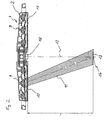
- FIG. 2 is a sectional view of a lamp body 4 in which a plurality of lamps 9 are provided.
- the lamp body 4 has a central axis 12 which is perpendicular to a plane in which the lamps 9 are arranged.
- the lamps 9 are arranged in a ring or in accordance with the shape of the lamp body 4.
- Each illuminant 9 is equipped with a device for bundling the light, here a refractor 10.
- a device for bundling the light here a refractor 10.
- separate reflectors or illuminants with integrated means for bundling the light can also be used.
- the surgical light forms several light fields 13 at different distances, i.e. the intersection of the light beam bundle 11 lies in planes at different distances.
- the distances of the levels or the luminous fields 13 from the lamp body 4 90 cm, 100 cm and 110 cm.
- the illuminants 9, which form the various luminous fields 13, are grouped together in terms of control technology and are activated as a function of the distance of the lamp body 4 from the operating field.
- the illuminants 9 with the refractors 10 are arranged at an incline, so that the axes of the light beam bundles 11 each intersect the central axis 12 at an intersection 14, which lies in the plane of the associated luminous field 13.
- the lamps 9 are evenly distributed in the plane in order to illuminate an obstacle which is introduced between the lamp body 4 and the operating field and thereby interrupts a light beam, which results in the formation of shadows, and thus to prevent or weaken the formation of shadows.
- Control device 7 arranged.
- the controller has devices for dimming and switching on and off the lighting means 9, such as current regulators, means for transmitting switching and setting information of the switching and setting elements of the operating device 8, a memory area for storing operating parameters and a CPU which consists of the switching - and setting information, calculated or determined on the basis of the stored operating parameters, the required settings for the means for dimming and switching on and off the lamps.
- the laser distance meter sends a laser beam with a red or, in another embodiment, green light, which can be seen better, into the center of the operating field. Since the laser beam has a wavelength in the visible range, the laser beam can also be used to visually check the orientation of the operating light 1, i.e. whether the center of the light field 13 is in the center of the operation field. However, since the light that is emitted by the operating light 1 for illuminating the operating field also has a portion at this wavelength, the distance measurement can be disturbed. For this reason, the light used to illuminate the operating field is dimmed during the measurement.
- a laser beam source which emits light in a wavelength range which is not in the visible range but in the infrared (IR) or ultraviolet (UV) range.
- Operating lights 1 radiate due to the use of filters, or illuminants that emit only a very small proportion of light in this wavelength range, e.g. LEDs, in this wavelength range no disturbing light.
- the sensor device 16 or parts of the sensor device 16 can also be arranged in other areas of the lamp body or on the support system 2.
- a trigger mechanism (not shown), here an acceleration sensor, which detects a movement of the lamp body and, after the movement has ended, gives a signal for correction, that is to say for the recalculation of the power values and the transmission of the power values to the lamps 9.
- the correction can also be triggered using other trigger mechanisms, e.g. a switch that detects whether a handle (sterile or non-sterile) of the operating light has been touched, or an operating element on the operating device 8.
- trigger mechanisms e.g. a switch that detects whether a handle (sterile or non-sterile) of the operating light has been touched, or an operating element on the operating device 8.
- the control device 7 is connected to the lamps 9, which are controlled in groups.
- a group is formed from a plurality of illuminants 9 which are controlled with the same performance parameters. Several groups are possible, the light rays 11 of the illuminants 9 of which are each directed to the same intersection 14.
- control device 7 is connected to the sensor device 16.
- the element for switching on / off switches the operating light 1 from a standby mode, in which the lamps 9 do not light, to an operating mode.
- the lamps 9 are operated in accordance with the setting of the setting elements.
- an external main switch (not shown) is provided to switch off completely by switching off the power supply.
- the element for adjusting the distance gives the control device 7 the information that the control device 7 processes the signal emitted by the sensor device 16.
- the lamp body 2 of the surgical lamp 1 is adjusted to the operating field, so that optimal lighting conditions (brightness, lighting angle and focusing) are present.
- the element for setting the distance on the operating device 8 is then actuated, thereby causing the distance between the lamp body 2 and the operating field to be detected. If the position of the lamp body 2 changes due to a requirement that the direction of illumination must be changed, the acceleration sensor detects that the lamp body 2 is being moved and transmits a corresponding signal to the control device 7.
- the correction values for the different distances are determined empirically for individual operating conditions (distance and lighting situation) and stored as a map in the memory area of the control device 7.
- control device 7 is provided with memory modules which can be changed subsequently and the software is designed in such a way that the brightness is set at different intervals by the sequence of a defined sequence and the correction values are then stored by executing a key combination.
- the sensor device 16 can also use an ultrasonic sensor to detect the distance.
- the ultrasonic sensor forms a sound cone that forms a diameter of 30 cm to 40 cm at a distance that occurs in this application, and thus the distance detection is carried out with less accuracy than when using a laser distance meter.
- the senor is an infrared sensor, which is inexpensive, but the detection result of the distance depends on the color of the detected area. Depending on the course of operations, however, the various conditions arise that there are either green or blue drapes, skin (wetted with orange-colored disinfectant), red muscle or white adipose tissue or bones in the illuminated field 13. Therefore, the acquisition is less accurate.
- the power of the illuminants 9 is not changed in order to change the luminous intensity of the emitted light, but the light beams 11 are weakened by mechanical diaphragms or dimmable foils in such a way that the luminous intensity required to keep the brightness constant is achieved.
Landscapes
- Health & Medical Sciences (AREA)
- Engineering & Computer Science (AREA)
- Surgery (AREA)
- Life Sciences & Earth Sciences (AREA)
- General Engineering & Computer Science (AREA)
- Veterinary Medicine (AREA)
- Medical Informatics (AREA)
- Molecular Biology (AREA)
- Animal Behavior & Ethology (AREA)
- General Health & Medical Sciences (AREA)
- Public Health (AREA)
- Biomedical Technology (AREA)
- Nuclear Medicine, Radiotherapy & Molecular Imaging (AREA)
- Heart & Thoracic Surgery (AREA)
- Pathology (AREA)
- Oral & Maxillofacial Surgery (AREA)
- Microelectronics & Electronic Packaging (AREA)
- Non-Portable Lighting Devices Or Systems Thereof (AREA)
- Circuit Arrangement For Electric Light Sources In General (AREA)
- Materials For Medical Uses (AREA)
- Eye Examination Apparatus (AREA)
- Dry Shavers And Clippers (AREA)
- Endoscopes (AREA)
- Measurement Of Optical Distance (AREA)
- Selective Calling Equipment (AREA)
Abstract
Description
Die Erfindung betrifft eine Operationsleuchte, die ein Leuchtfeld auf dem Operationsfeld erzeugt, und eine Einrichtung zur Einstellung der Leuchtintensität der Leuchtmittel in Abhängigkeit von dem Abstand zwischen der Operationsleuchte und dem Operationsfeld.The invention relates to an operating light that generates a luminous field on the operating field, and a device for adjusting the luminous intensity of the lamps as a function of the distance between the operating light and the operating field.
Eine Möglichkeit der Ausführung von Operationsleuchten sind so genannte Großspiegelleuchten. Hierbei ist die Lichtquelle eine Halogenlampe oder Gasentladungslampe, die im Brennpunkt eines großen Reflektors mit einem Durchmesser von ca. 500 mm bis 1000 mm angeordnet ist. Durch eine Verschiebung der Lichtquelle auf der Mittelachse des Reflektors, und damit mehr oder weniger aus dem oder in den optimalen Brennpunkt des Reflektors, wird der Durchmesser des Leuchtfelds, d.h. der beleuchtete Durchmesser im Operationsfeld vergrößert oder verkleinert, und der Fokuspunkt verändert, d.h. der Abstand der hellsten beleuchteten Stelle, in der sich die reflektierten Lichtstrahlen schneiden, von dem Leuchtenkörper der Operationsleuchte auf einer Mittelachse des Leuchtenkörpers verändert. Hierfür ist eine aufwändige Mechanik erforderlich, die eine prozesssichere leichtgängige Bedienung ohne großen Betätigungsaufwand des Bedieners, ermöglicht. Dadurch ändert sich die Helligkeit, da die Lichtmenge auf eine größere Fläche verteilt wird und die Verteilung der Leuchtstärke über dem Durchmesser des Leuchtfelds, und somit auch die Leuchtstärke im Zentrum des Leuchtfelds.So-called large mirror lights are one way of implementing surgical lights. The light source is a halogen lamp or gas discharge lamp, which is arranged in the focal point of a large reflector with a diameter of approximately 500 mm to 1000 mm. By moving the light source on the central axis of the reflector, and thus more or less from or into the optimal focal point of the reflector, the diameter of the illuminated field, i.e. the illuminated diameter in the operating field increases or decreases, and the focus point changes, i.e. the distance of the brightest illuminated spot, in which the reflected light beams intersect, changes from the lamp body of the surgical lamp on a central axis of the lamp body. This requires complex mechanics that enable process-reliable, smooth operation without much effort on the part of the operator. This changes the brightness, since the amount of light is distributed over a larger area and the distribution of the luminosity over the diameter of the luminous field, and thus also the luminosity in the center of the luminous field.
Eine andere Ausführung sind aufgelöste Lichtsysteme. Hierbei umfasst die Operationsleuchte in der Regel einen zentralen Scheinwerfer oder ein zentrales Lichtmodul, der/das starr am Leuchtenkörper befestigt ist und mehrere Scheinwerfer oder Lichtmodule in einer ringförmigen Anordnung um den zentralen Scheinwerfer oder das zentrale Lichtmodul aufweist. Die Veränderung der Richtung des Lichtaustritts aus den äußeren Scheinwerfern oder Lichtmodulen ist über radial verschwenkbare Leuchtmittel oder Reflektoren realisiert, oder die gesamten Scheinwerfer oder Lichtmodule sind radial schwenkbar verstellbar, so dass der Fokuspunkt der Lichtstrahlen aus den äußeren Scheinwerfern oder Lichtmodulen seinen Abstand vom Leuchtenköper auf der Mittelachse verändert. Auch dadurch ändert sich die gesamte Helligkeit, und die Verteilung der Leuchtstärke über dem Durchmesser des Leuchtfelds, und somit auch die Leuchtstärke im Zentrum des Leuchtfelds. Dabei ist ebenfalls eine aufwändige Mechanik zur synchronen, prozesssicheren Verstellung der äußeren Leuchtmittel, Reflektoren oder Lichtmodulen erforderlich.Another version is dissolved lighting systems. In this case, the surgical light generally comprises a central headlight or a central light module, which is rigidly attached to the lamp body and has a plurality of headlights or light modules in an annular arrangement around the central headlight or the central light module. The change in the direction of the light exit from the outer headlights or light modules is realized via radially pivotable lamps or reflectors, or the entire headlights or light modules can be pivoted radially so that the focal point of the light beams from the outer headlights or light modules is at a distance from the body of the lamp on the Central axis changed. This also changes the overall brightness, and the distribution of the luminosity over the diameter of the luminous field, and thus also the luminosity in the center of the luminous field. A complex mechanism for synchronous, process-reliable adjustment of the external illuminants, reflectors or light modules is also required.
Die Offenlegung
Weiterhin zeigt die
Eine weitere Art von Operationsleuchten ist ohne die Verstellmöglichkeit des Leuchtfelddurchmessers und des Abstands des Fokuspunkts ausgeführt. Hierbei sind die lichttechnischen Daten, Leuchtfelddurchmesser und Fokuspunkt für einen Arbeitspunkt optimal eingestellt. Eine Veränderung des Leuchtfelddurchmessers ist hier nur durch eine Veränderung des Abstands des Leuchtenkörpers vom Operationsfeld möglich.Another type of operating lights is designed without the possibility of adjusting the diameter of the light field and the distance of the focus point. The lighting data, luminous field diameter and focus point are optimally set for a working point. A change in the light field diameter is only possible here by changing the distance of the light body from the operation field.
Bei diesen Ausführungen von Operationsleuchten ändert sich die Beleuchtungsstärke im Zentrum des Leuchtfelds bei einer Veränderung des Abstands zwischen der Operationsleuchte und dem Operationsfeld zum einen, da sich der Abstand von der Strahlungsquelle verändert, was zu einer Abnahme der Strahlungsintensität bei einer Vergrößerung der Entfernung oder Zunahme der Strahlungsintensität bei einer Verringerung der Entfernung führt, und zum anderen, da die Verteilung der Leuchtstärke im Leuchtfeld nicht mehr normgerecht ist, und somit die Leuchtstärke im Zentrum abnimmt.In these versions of surgical lights, the illuminance in the center of the illuminated field changes when the distance between the surgical lamp and the surgical field changes, on the one hand, because the distance from the radiation source changes, which leads to a decrease in the radiation intensity as the distance increases or the distance increases Radiation intensity leads to a reduction in the distance, and on the other hand, since the distribution of the luminosity in the luminous field is no longer in accordance with the norm, and thus the luminance in the center decreases.
Das Gebrauchsmuster
Es ist Aufgabe der Erfindung, eine Operationsleuchte zur Verfügung zu stellen, die kostengünstig die Möglichkeit bietet, die Beleuchtungsstärke bei einer Veränderung des Abstands zwischen der Operationsleuchte und dem Operationsfeld selbsttätig konstant zu halten.It is an object of the invention to provide an operating room lamp which offers the possibility of keeping the illuminance automatically constant when the distance between the operating lamp and the operating field changes.
Die Aufgabe wird mit den Merkmalen des Anspruchs 1 gelöst. Weiterbildungen der Erfindung sind in den Unteransprüchen beschrieben.The object is achieved with the features of claim 1. Developments of the invention are described in the subclaims.
Die Operationsleuchte bietet durch das Aufweisen einer Sensoreinrichtung zum Messen des Abstands zwischen der Operationsleuchte und dem Operationsfeld und einer Ansteuerung der Leuchtmittel die Möglichkeit, die Leuchtintensität der Leuchtmittel so zu verändern, dass die Helligkeit im Operationsfeld bei einer Veränderung des Abstands konstant bleibt. Dies erfolgt ohne mechanische Verstellmittel.By having a sensor device for measuring the distance between the surgical light and the surgical field and controlling the illuminants, the surgical light offers the possibility of changing the luminous intensity of the illuminants such that the brightness in the surgical field remains constant when the distance changes. This is done without mechanical adjustment means.
Die Erfindung wird anhand eines Ausführungsbeispiels unter Bezugnahme auf die beigefügten Zeichnungen erläutert.
- Fig. 1
- ist eine perspektivische Ansicht eines Ausführungsbei- spiels der erfindungsgemäßen Operationsleuchte.
- Fig. 2
- ist eine Schnittansicht eines Leuchtenkörpers mit der Anordnung einer Sensoreinrichtung zur Abstandserfas- sung.
- Fig. 1
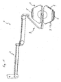
- is a perspective view of an embodiment of the surgical light according to the invention.
- Fig. 2
- is a sectional view of a lamp body with the arrangement of a sensor device for distance detection.
Zum unsterilen Positionieren des Leuchtkörpers 4 sind an den beiden Hälften des Leuchtenkörpers 4 je ein Griff 5, 6 angebracht. Die beiden Hälften des Leuchtenkörpers 4 sind drehfest miteinander verbunden, so dass sich beim Verschwenken der einen Hälfte die andere Hälfte mitbewegt, um die Lichtaustrittsflächen immer in einer Ebene zu halten.For non-sterile positioning of the
Zum sterilen Positionieren des Leuchtkörpers ist ein Handgriff im Zentrum der Lichtaustrittsöffnung angeordnet. Über den Handgriff wird eine Hülse gesteckt, die sterilisierbar ist.A handle is arranged in the center of the light exit opening for sterile positioning of the luminous element. A sleeve that can be sterilized is placed over the handle.
Innerhalb des Leuchtenkörpers 4 ist eine Steuerungsvorrichtung 7 angeordnet. Die Steuerungsvorrichtung 7 muss nicht zwingend in dem Leuchtenkörper 4 angeordnet sein, sondern kann auch in einem separaten Gehäuse, das am Leuchtenkörper 4 oder an der Aufhängevorrichtung 3 angeordnet ist, untergebracht sein. Alternativ besteht auch die Möglichkeit, dass sich die Steuerungsvorrichtung 7 in einer nicht gezeigten externen Bedieneinheit befindet, die sich in einer Medizinischen Versorgungseinheit oder in/an einer Wand befindet.A
An der Außenseite des Leuchtenkörpers 4 ist eine Bedienvorrichtung 8 angeordnet. Die Bedienvorrichtung 8 kann sich aber auch in einem separaten Gehäuse befinden, das sich beispielsweise am Leuchtenkörper 4, an der Aufhängevorrichtung 3 oder in einer Medizinischen Versorgungseinheit oder in/an einer Wand befindet.
In einer alternativen Ausführungsform ist auch das Vorsehen von nur einem Leuchtmittel möglich.In an alternative embodiment, it is also possible to provide only one light source.
Jedes Leuchtmittel 9 ist mit einer Vorrichtung zum Bündeln des Lichts, hier einem Refraktor 10, ausgestattet. Anstelle der separaten Refraktoren 10 können auch separate Reflektoren oder Leuchtmittel mit integrierten Mitteln zum Bündeln des Lichts verwendet werden.Each illuminant 9 is equipped with a device for bundling the light, here a
Das gebündelte Licht der Leuchtmittel 9, tritt in einem Lichtstrahl 11 aus dem Refraktor 10 aus. Ein Lichtstrahl 11 beleuchtet jeweils ein gesamtes Leuchtfeld 13.The bundled light from the
In einer alternativen Ausführungsform bildet die Operationsleuchte mehrere Leuchtfelder 13 in verschiedenen Abständen, d.h. der Schnittpunkt der Lichtstrahlbündel 11 liegt in Ebenen in verschiedenen Abständen. In einer speziellen Ausführungsform betragen die Abstände der Ebenen, bzw. der Leuchtfelder 13 vom Leuchtenkörper 4, 90 cm, 100 cm und 110 cm. Die Leuchtmittel 9, die die verschiedenen Leuchtfelder 13 bilden, sind steuerungstechnisch gruppenweise zusammengefasst und werden in Abhängigkeit von dem Abstand des Leuchtenkörpers 4 von dem Operationsfeld aktiviert.In an alternative embodiment, the surgical light forms
Die Leuchtmittel 9 mit den Refraktoren 10 sind geneigt angeordnet, so dass die Achsen der Lichtstrahlbündel 11 die Mittelachse 12 jeweils in jeweils einem Schnittpunkt 14, der in der Ebene des zugehörigen Leuchtfelds 13 liegt, schneiden.The
Die Leuchtmittel 9 sind in der Ebene gleichmäßig verteilt, um ein Hindernis, das zwischen den Leuchtenkörper 4 und das Operationsfeld eingebracht wird und dadurch ein Lichtstrahlenbündel unterbricht, was eine Schattenbildung zur Folge hat, zu unterleuchten und somit die Schattenbildung zu verhindern oder abzuschwächen.The
In dem Leuchtenkörper 4 ist die nicht gezeigte Steuerungsvorrichtung 7 angeordnet. Die Steuerung weist Einrichtungen zum Dimmen und Ein- und Ausschalten der Leuchtmittel 9, wie z.B. Stromregler, Mittel zum Übertragen von Schalt- und Einstellinformationen der Schalt- und Einstellelemente der Bedienvorrichtung 8, einen Speicherbereich zum Abspeichern von Betriebsparametern und eine CPU, die aus den Schalt- und Einstellinformationen, an Hand der abgespeicherten Betriebsparameter, die erforderlichen Einstellungen für die Mittel zum Dimmen und Ein- und Ausschalten der Leuchtmittel berechnet oder bestimmt, auf.In the
Im zentralen Bereich des Leuchtenkörpers 4 ist auf der Seite der Lichtaustrittsfläche 15 eine Sensoreinrichtung 16 angeordnet. Diese Sensoreinrichtung 16 erfasst den Abstand zwischen der Lichtaustrittsfläche 15 des Leuchtenkörpers 4 und dem Operationsfeld, wandelt diese Information in elektrische Signale um und gibt diese an die Steuerungsvorrichtung 7 weiter. Die Sensoreinrichtung 16 verwendet zur Abstandsmessung einen Laser-Abstandsmesser, der eine punktgenaue Abstandsmessung ermöglicht, die nicht von der Farbe oder der Struktur der Oberfläche des Operationsfelds abhängig ist.A sensor device 16 is arranged in the central region of the
Der Laser-Abstandsmesser sendet während des Messvorgangs einen Laserstrahl mit einem roten oder in einer anderen Ausführungsform grünen Licht, das besser erkennbar ist, in das Zentrum des Operationsfelds. Da der Laserstrahl eine Wellenlänge im sichtbaren Bereich aufweist, kann der Laserstrahl auch zur visuellen Kontrolle der Orientierung der Operationsleuchte 1 verwendet werden, d.h. ob das Zentrum des Leuchtfelds 13 im Zentrum des Operationsfeld liegt. Da das Licht, das durch die Operationsleuchte 1 zur Beleuchtung des Operationsfelds ausgestrahlt wird, jedoch ebenfalls einen Anteil bei dieser Wellenlänge aufweist, kann die Abstandsmessung gestört werden. Aus diesem Grund wird während der Messung das Licht, das zur Beleuchtung des Operationsfelds dient, abgedimmt.During the measuring process, the laser distance meter sends a laser beam with a red or, in another embodiment, green light, which can be seen better, into the center of the operating field. Since the laser beam has a wavelength in the visible range, the laser beam can also be used to visually check the orientation of the operating light 1, i.e. whether the center of the
Um das Dimmen zu vermeiden, gibt es in einer weiteren Ausführungsform eine Laserstrahlquelle, die Licht in einem Wellenlängenbereich abstrahlt, der nicht im sichtbaren Bereich, sondern im Infrarot (IR)- oder Ultraviolett (UV)-Bereich liegt. Operationsleuchten 1 strahlen auf Grund der Verwendung von Filtern, oder von Leuchtmitteln, die nur einen sehr geringen Anteil von ein Licht in diesem Wellenlängenbereich abstrahlen, wie z.B. LEDs, in diesem Wellenlängenbereich kein störendes Licht aus.In order to avoid dimming, in a further embodiment there is a laser beam source which emits light in a wavelength range which is not in the visible range but in the infrared (IR) or ultraviolet (UV) range. Operating lights 1 radiate due to the use of filters, or illuminants that emit only a very small proportion of light in this wavelength range, e.g. LEDs, in this wavelength range no disturbing light.
Zur besseren Ausrichtung der Operationsleuchte 1 bei einer ungestörten Abstandsmessung gibt es in einer zusätzlichen Ausführungsform eine Kombination einer Laserstrahlquelle, die sichtbares Licht zum Ausrichten ausstrahlt, und einer Laserstrahlquelle, die Licht im UV- oder IR-Bereich zur Abstandsmessung ausstrahlt.For better alignment of the surgical light 1 with an undisturbed distance measurement, there is an additional embodiment in a combination of a laser beam source that emits visible light for alignment and a laser beam source that emits light in the UV or IR range for distance measurement.
In alternativen Ausführungsformen kann die Sensoreinrichtung 16, oder Teile der Sensoreinrichtung 16 auch in anderen Bereichen des Leuchtenkörpers oder am Tragsystem 2 angeordnet sein. Innerhalb des Leuchtenkörpers 2 ist ein (nicht gezeigter) Auslösemechanismus, hier ein Beschleunigungssensor, vorgesehen, der eine Bewegung des Leuchtenkörpers erfasst und nach Abschluss der Bewegung ein Signal zur Korrektur, also zur Neuberechnung der Leistungswerte und die Übertragung der Leistungswerte an die Leuchtmittel 9 gibt.In alternative embodiments, the sensor device 16 or parts of the sensor device 16 can also be arranged in other areas of the lamp body or on the
Das Auslösen der Korrektur kann auch mit Hilfe anderer Auslösemechanismen, z.B. einem Schalter, der erfasst, ob ein Griff (steril oder unsteril) der Operationsleuchte berührt wurde, oder einem Bedienelement an der Bedienvorrichtung 8, ausgeführt werden.The correction can also be triggered using other trigger mechanisms, e.g. a switch that detects whether a handle (sterile or non-sterile) of the operating light has been touched, or an operating element on the operating device 8.
Die Steuerungsvorrichtung 7 ist mit den Leuchtmitteln 9 verbunden, die gruppenweise angesteuert werden. Eine Gruppe wird aus mehreren Leuchtmitteln 9 gebildet, die mit den gleichen Leistungsparametern angesteuert werden. Es sind mehrere Gruppen möglich, deren Lichtstrahlen 11 der Leuchtmittel 9 auf jeweils den gleichen Schnittpunkt 14 gerichtet sind.The
Weiterhin ist die Steuerungsvorrichtung 7 mit der Sensoreinrichtung 16 verbunden.Furthermore, the
Die Steuerungsvorrichtung 7 ist ebenfalls mit der Bedienvorrichtung 8 verbunden. An der Bedienvorrichtung 8 ist
- ein Element zum Ein-/Ausschalten,
- ein Element zur Abstandseinstellung (Abspeichern des momentanen Abstands) und
- ein Element zur Helligkeitseinstellung vorgesehen.
- an element for switching on / off,
- an element for setting the distance (saving the current distance) and
- an element for brightness adjustment is provided.
Das Element zum Ein-/Ausschalten schaltet die Operationsleuchte 1 von einem Standby-Modus, in der die Leuchtmittel 9 nicht leuchten, in einen Betriebsmodus. Dabei werden die Leuchtmittel 9 entsprechend der Einstellung der Einstellelemente betrieben. Zum vollständigen Ausschalten durch Abschalten der Stromversorgung ist ein nicht gezeigter externer Hauptschalter vorgesehen.The element for switching on / off switches the operating light 1 from a standby mode, in which the
Das Element zur Abstandseinstellung gibt an die Steuerungsvorrichtung 7 die Information, das durch die Sensoreinrichtung 16 abgegebene Signal durch die Steuerungsvorrichtung 7 zu verarbeiten.The element for adjusting the distance gives the
Im Betrieb wird der Leuchtenkörper 2 der Operationsleuchte 1 auf das Operationsfeld eingestellt, so dass optimale Beleuchtungsbedingungen (Helligkeit, Beleuchtungswinkel und Fokussierung) vorliegen. Anschließend wird das Element zur Abstandseinstellung an der Bedienvorrichtung 8 betätigt und damit veranlasst, dass der Abstand des Leuchtenkörpers 2 von dem Operationsfeld erfasst wird. Bei einer Veränderung der Position des Leuchtenkörpers 2 auf Grund eines Erfordernisses, dass die Beleuchtungsrichtung verändert werden muss, erkennt der Beschleunigungssensor, dass der Leuchtenkörper 2 bewegt wird und überträgt ein entsprechendes Signal an die Steuerungsvorrichtung 7. Nach Beendigung der Bewegung wertet die Steuerungsvorrichtung 7 die durch die Sensoreinrichtung 16 übermittelten Signale bezüglich des nun vorliegenden Abstands aus, wählt zugehörigen Korrekturwerte aus, die in dem Speicherbereich der Steuerungsvorrichtung 7 abgelegt sind, und ermittelt somit die erforderlichen Leistungswerte für die Leuchtmittel 9, die an die Einrichtungen zum Dimmen und Ein-und Ausschalten der Leuchtmittel 9 weitergeben werden. Die Beleuchtungsstärke wird damit so gewählt, dass die Helligkeit im Operationsfeld der Helligkeit vor der Positionsänderung des Leuchtenkörpers entspricht.In operation, the
Die Korrekturwerte für die verschiedenen Abstände werden für einzelne Betriebsbedingungen (Abstand und Beleuchtungssituation) empirisch ermittelt und als Kennfeld in dem Speicherbereich der Steuerungsvorrichtung 7 abgespeichert.The correction values for the different distances are determined empirically for individual operating conditions (distance and lighting situation) and stored as a map in the memory area of the
Bei Bedarf kann die Operationsleuchte nachträglich kalibriert werden. Hierzu ist die Steuerungsvorrichtung 7 mit nachträglich veränderbaren Speicherbausteinen versehen und die Software so gestaltet, dass durch die Abfolge einer definierten Sequenz die Helligkeit bei verschiedenen Abständen eingestellt wird und dann durch Ausführen einer Tastenkombination die Korrekturwerte abgespeichert werden.If necessary, the surgical light can be calibrated later. For this purpose, the
In einer alternativen Ausführungsform kann die Sensoreinrichtung 16 auch einen Ultraschallsensor zur Erfassung des Abstands verwenden. Hierbei muss allerdings in Kauf genommen werden, dass der Ultraschallsensor einen Schallkegel bildet, der in einem in dieser Anwendung auftretenden Abstand einen Durchmesser von 30 cm bis 40 cm ausbildet, und somit die Abstandserkennung ungenauer durchgeführt wird, als bei der Verwendung eines Laser-Abstandsmessers.In an alternative embodiment, the sensor device 16 can also use an ultrasonic sensor to detect the distance. However, it must be accepted that the ultrasonic sensor forms a sound cone that forms a diameter of 30 cm to 40 cm at a distance that occurs in this application, and thus the distance detection is carried out with less accuracy than when using a laser distance meter.
Eine weitere Alternative im Hinblick auf den Sensor ist ein Infrarotsensor, der zwar kostengünstig, aber das Erfassungsergebnis des Abstands abhängig von der Farbe der erfassten Fläche ist. Bei Operationen treten je nach Verlauf jedoch die verschiednen Bedingungen auf, dass sich entweder grüne oder blaue Abdecktücher, Haut (benetzt mit orange-farbigem Desinfektionsmittel), rotes Muskel- oder weißes Fettgewebe oder Knochen im Leuchtfeld 13 befinden. Daher ist die Erfassung ungenauer.Another alternative with regard to the sensor is an infrared sensor, which is inexpensive, but the detection result of the distance depends on the color of the detected area. Depending on the course of operations, however, the various conditions arise that there are either green or blue drapes, skin (wetted with orange-colored disinfectant), red muscle or white adipose tissue or bones in the illuminated
In weiteren alternativen Ausführungsformen wird nicht die Leistung der Leuchtmittel 9 verändert, um die Leuchtintensität des abgestrahlten Lichts zu verändern, sondern die Lichtstrahlen 11 durch mechanische Blenden oder dimmbare Folien so abgeschwächt, dass die für die Konstanthaltung der Helligkeit erforderliche Lichtstärke erreicht wird.In further alternative embodiments, the power of the
Claims (15)
- Surgical light (1) comprising
a lamp body (4)
having a light emergence face (15) and
at least one illuminant (9) suitable for radiating a light beam (11) to a surgical site (13),
a sensor device (16) for detecting a distance between the lamp body (4) and the surgical site,
a control device (7), and
a device for dimming and switching on and switching off of the illuminants (9), characterized in that
the control device (7) is adapted to analyze the distance, detected by the sensor device (16), between the light emergence face (15) of the light head (4) and the surgical site and to transmit the power output values for the illuminants (9) necessary for the detected distance to the device for dimming and switching on and switching off of the illuminants (9) so that an illumination intensity of the illuminants (9) is changed such that a brightness in the surgical site remains constant upon a change of the distance. - Surgical light according to claim 1, characterized in that a central control device (7) is provided which is connected to the sensor device (16) for detecting the distance and the devices for controlling the intensity of the radiated light.
- Surgical light according to any of the preceding claims, characterized in that the device for controlling the intensity of the radiated light is an electrical output regulator for driving the illuminant (9).
- Surgical light according to any of claim 2 or 3, characterized in that the central control device (7) comprises devices for storing data or algorithms.
- Surgical light according to any of the preceding claims, characterized in that an actuator is provided which actuates a change of the intensity of the radiated light.
- Surgical light according to claim 5, characterized in that the actuator comprises an acceleration sensor.
- Surgical light according to claim 5, characterized in that the actuator comprises a switch in a handle.
- Surgical light according to any of the preceding claims, characterized in that at least one device for calibrating the control is provided.
- Surgical light according to any of claims 1 to 8, characterized in that the sensor device for measuring the distance is an ultrasonic sensor.
- Surgical light according to any of claims 1 to 8, characterized in that the sensor device (16) for measuring the distance is an infrared sensor.
- Surgical light according to any of claims 1 to 8, characterized in that the sensor device (16) for measuring the distance is a laser sensor.
- Surgical light according to claim 11, characterized in that the laser sensor radiates light in the visible wavelength range.
- Surgical light according to claim 11, characterized in that the laser sensor radiates light in the non-visible wavelength range.
- Surgical light according to claim 13, characterized in that the surgical light comprises a laser beam source which radiates light in the visible wavelength range.
- Surgical light according to claim 1, characterized in that multiple illuminants (9) are collected to groups, the pencils (11) of light beams of which having an intersection point in the plane of the related light field (13), respectively, and that the light fields (13) have different distances to the lamp body (4).
Priority Applications (2)
| Application Number | Priority Date | Filing Date | Title |
|---|---|---|---|
| EP08014768.9A EP2136129B2 (en) | 2008-06-20 | 2008-08-20 | Operating light with distance-dependant brightness control |
| PL08014768T PL2136129T3 (en) | 2008-06-20 | 2008-08-20 | Operating light with distance-dependant brightness control |
Applications Claiming Priority (2)
| Application Number | Priority Date | Filing Date | Title |
|---|---|---|---|
| EP08011296A EP2136128B1 (en) | 2008-06-20 | 2008-06-20 | Operating light |
| EP08014768.9A EP2136129B2 (en) | 2008-06-20 | 2008-08-20 | Operating light with distance-dependant brightness control |
Publications (3)
| Publication Number | Publication Date |
|---|---|
| EP2136129A1 EP2136129A1 (en) | 2009-12-23 |
| EP2136129B1 EP2136129B1 (en) | 2011-01-19 |
| EP2136129B2 true EP2136129B2 (en) | 2019-12-18 |
Family
ID=40039670
Family Applications (2)
| Application Number | Title | Priority Date | Filing Date |
|---|---|---|---|
| EP08011296A Revoked EP2136128B1 (en) | 2008-06-20 | 2008-06-20 | Operating light |
| EP08014768.9A Active EP2136129B2 (en) | 2008-06-20 | 2008-08-20 | Operating light with distance-dependant brightness control |
Family Applications Before (1)
| Application Number | Title | Priority Date | Filing Date |
|---|---|---|---|
| EP08011296A Revoked EP2136128B1 (en) | 2008-06-20 | 2008-06-20 | Operating light |
Country Status (7)
| Country | Link |
|---|---|
| US (1) | US8292804B2 (en) |
| EP (2) | EP2136128B1 (en) |
| JP (1) | JP5697855B2 (en) |
| CN (2) | CN106224834A (en) |
| AT (2) | ATE496257T1 (en) |
| DE (3) | DE202008018046U1 (en) |
| PL (2) | PL2136128T3 (en) |
Cited By (1)
| Publication number | Priority date | Publication date | Assignee | Title |
|---|---|---|---|---|
| US11706857B2 (en) | 2020-03-30 | 2023-07-18 | Trumpf Medizin Systeme Gmbh + Co. Kg | Surgical light system and method for operating the surgical light system |
Families Citing this family (50)
| Publication number | Priority date | Publication date | Assignee | Title |
|---|---|---|---|---|
| ATE477452T1 (en) * | 2008-06-20 | 2010-08-15 | Trumpf Medizin Systeme Gmbh & Co Kg | OPERATIONAL LIGHT WITH SUSPENSION DEVICE |
| US8172751B2 (en) * | 2008-11-10 | 2012-05-08 | Steris Corporation | Method and apparatus for electronic adjustment of illuminance of surgical lamp |
| WO2012023090A1 (en) * | 2010-08-17 | 2012-02-23 | Koninklijke Philips Electronics N.V. | Surgical lamp for broadband and narrowband illumination |
| EP2434202B2 (en) | 2010-09-28 | 2021-04-21 | TRUMPF Medizin Systeme GmbH + Co. KG | Operating light with sterile operating device |
| US11454361B2 (en) * | 2010-10-21 | 2022-09-27 | Ole Falk Smed | Automatically adjusting task light |
| CN102121634B (en) * | 2010-12-30 | 2013-01-02 | 东莞勤上光电股份有限公司 | LED shadowless lamp |
| EP2663803B1 (en) * | 2011-01-14 | 2016-05-18 | Ondal Holding GmbH | Lighting device |
| EP2495487B1 (en) * | 2011-03-02 | 2014-06-11 | TRUMPF Medizin Systeme GmbH + Co. KG | Operation lamp and method for illuminating an operation point |
| USD699879S1 (en) | 2011-08-19 | 2014-02-18 | Trumpf Medizin Systeme Gmbh + Co. Kg | Medical lamp |
| KR101748622B1 (en) * | 2012-03-21 | 2017-06-20 | 한화테크윈 주식회사 | Side light apparatus and light apparatus using that of chip mounter |
| CN103574521A (en) * | 2012-08-08 | 2014-02-12 | 康源医疗设备股份有限公司 | Focusing method and structure of LED light source |
| US9730851B2 (en) | 2012-09-07 | 2017-08-15 | Allen Medical Systems, Inc. | Surgical support system |
| US9107792B2 (en) | 2012-09-07 | 2015-08-18 | Allen Medical Systems, Inc. | Carriage for a surgical boot of a hip distractor |
| TW201420958A (en) * | 2012-11-16 | 2014-06-01 | Convida Healthcare & Systems Corp | Illumination range electrical adjusting structure |
| FR3003011A1 (en) * | 2013-03-05 | 2014-09-12 | Maquet Sas | LUMINANCE-ASSISTED LIGHTING DEVICE |
| US9470405B2 (en) * | 2013-03-15 | 2016-10-18 | Stryker Corporation | Surgical light with beam redirecting optics |
| CN103162191A (en) * | 2013-03-19 | 2013-06-19 | 苏州沃伦韦尔高新技术股份有限公司 | Operating lamp with distance measurement feedback illuminance automatic regulating function |
| US9310096B2 (en) | 2013-08-22 | 2016-04-12 | Nortek Air Solutions, LLC. | Overhead support system having adjustable lighting elements |
| CH709254A1 (en) * | 2014-02-03 | 2015-08-14 | Regent Beleuchtungskörper Ag | Lamp. |
| CN103994374A (en) * | 2014-05-29 | 2014-08-20 | 许保康 | Novel shadowless lamp for operating room |
| DE102015106519B4 (en) | 2015-04-28 | 2025-07-10 | Stryker European Operations Holdings LLC (n.d.Ges.d. Staates Delaware) | Method and device for controlling an operating light |
| KR101708701B1 (en) * | 2015-06-17 | 2017-02-21 | 한희상 | An Apparatus for Verifying a Surgical Site Automatically and a Method for Controlling a Light Automatically Using the Same |
| US11153953B2 (en) * | 2015-07-31 | 2021-10-19 | Stryker Corporation | Method and system for maximizing the output of surgical lights |
| DE102015113339A1 (en) * | 2015-08-13 | 2017-02-16 | Karl Leibinger Medizintechnik Gmbh & Co. Kg | Operating light with brightness control |
| DE102015113337A1 (en) * | 2015-08-13 | 2017-02-16 | Karl Leibinger Medizintechnik Gmbh & Co. Kg | Operating light with variable light field geometry |
| DE102015113336B4 (en) * | 2015-08-13 | 2017-10-05 | Karl Leibinger Medizintechnik Gmbh & Co. Kg | Handle device for a surgical light with sensors and surgical light |
| CN106813152A (en) * | 2015-12-02 | 2017-06-09 | 安钛医疗设备股份有限公司 | Focusing luminosity reinforcing device for operating lamp |
| FR3044889B1 (en) * | 2015-12-15 | 2021-12-24 | Surgiris | MEDICAL LIGHTING SYSTEM, PARTICULARLY OPERATIVE, AND METHOD FOR CONTROLLING SUCH A LIGHTING SYSTEM |
| US10240751B2 (en) * | 2016-03-24 | 2019-03-26 | TurningMode, LLC | Systems and methods of illumination |
| FR3052536B1 (en) * | 2016-06-08 | 2018-06-01 | Maquet Sas | MEDICAL LIGHTING DEVICE WITH GOOD POSITIONING ASSISTING SYSTEM |
| FR3055688B1 (en) * | 2016-09-05 | 2018-09-07 | Maquet Sas | MEDICAL LIGHTING DEVICE WITH LEDS ORIENTED BY PRE-CUTTED TONGUES IN A PRINTED CIRCUIT BOARD |
| CN108050407B (en) * | 2017-12-01 | 2019-05-17 | 浙江海洋大学 | A kind of intelligence news interview lamp |
| EP3781976B1 (en) | 2018-04-18 | 2025-05-28 | Gentex Corporation | Confined field of view illumination in surgical microscopy |
| CN109185735B (en) * | 2018-08-17 | 2021-01-19 | 广州金利节能科技有限公司 | Energy-saving lamp |
| CN109163251B (en) * | 2018-09-14 | 2021-06-25 | 吉林大学 | a shadowless lamp |
| DE202018106344U1 (en) * | 2018-11-08 | 2018-11-14 | Karl Leibinger Medizintechnik Gmbh & Co. Kg | Surgical lights housing |
| CN109348108B (en) * | 2018-11-12 | 2022-04-08 | 南京迈瑞生物医疗电子有限公司 | Surgical field camera, adjusting method of surgical field camera, computer equipment and readable storage medium |
| CN109842975B (en) * | 2019-03-14 | 2025-01-14 | 江门市蓬江区天利新科技有限公司 | Light-emitting diode driving system based on power line transmission signal |
| US11484382B2 (en) | 2019-04-24 | 2022-11-01 | American Sterilizer Company | System and method for identification of illumination abnormalities and automatic compensation therefor |
| US11612027B2 (en) * | 2019-06-17 | 2023-03-21 | Armament Systems And Procedures, Inc. | Settable multi-spectral flashlight |
| EP3996576A2 (en) * | 2019-07-08 | 2022-05-18 | Stryker Corporation | Systems and methods for targeted spectral illumination |
| EP4096563B1 (en) | 2020-01-31 | 2025-04-23 | American Sterilizer Company | Proximity detection for a surgical light |
| KR102243808B1 (en) * | 2020-10-14 | 2021-04-23 | 대한민국 | Multifocal split led searchlight system |
| EP4066775B1 (en) | 2021-03-31 | 2025-12-10 | Baxter Medical Systems GmbH + Co. KG | Indication system for a surgical lighting apparatus |
| DE102021108309A1 (en) * | 2021-04-01 | 2022-10-06 | Drägerwerk AG & Co. KGaA | lighting unit and lamp |
| USD1014832S1 (en) | 2021-09-16 | 2024-02-13 | Trumpf Medizin Systeme Gmbh + Co. Kg | Support arm for a suspension apparatus for a medical lamp |
| USD1015622S1 (en) | 2021-09-16 | 2024-02-20 | Trumpf Medizin Systeme Gmbh + Co. Kg | Suspension apparatus for a medical lamp |
| DE102021129294A1 (en) | 2021-11-10 | 2023-05-11 | lxpro GmbH sp. z o.o oddzial w Polsce | lighting device |
| DE102022122412A1 (en) * | 2022-09-05 | 2024-03-07 | Drägerwerk AG & Co. KGaA | Illumination device and illumination method with contrast change |
| IT202300009318A1 (en) * | 2023-05-10 | 2024-11-10 | F A R O Fabbrica Apparecchiature Razionali Odontoiatriche S P A | Operating lamp |
Citations (2)
| Publication number | Priority date | Publication date | Assignee | Title |
|---|---|---|---|---|
| WO2003083359A2 (en) † | 2002-03-28 | 2003-10-09 | Focus Repair Services, Ltd. | Lighting apparatus with electronic shadow compensation |
| JP2004288474A (en) † | 2003-03-24 | 2004-10-14 | Takeuchi Seisakusho:Kk | LED array type illuminator |
Family Cites Families (27)
| Publication number | Priority date | Publication date | Assignee | Title |
|---|---|---|---|---|
| DE1197827C2 (en) | 1964-04-11 | 1976-02-26 | Orginal Hanau Quarzlampen GmbH, 6450 Hanau | SURGICAL LIGHT |
| FR1495007A (en) | 1966-08-05 | 1967-09-15 | Surgical lighting device | |
| DE2141351C3 (en) * | 1971-08-18 | 1979-12-06 | Original Hanau Heraeus Gmbh, 6450 Hanau | Operating light |
| FR2339129A2 (en) * | 1976-01-21 | 1977-08-19 | Angenieux P Ets | LIGHTING PROJECTOR |
| US4196460A (en) * | 1978-07-14 | 1980-04-01 | Sybron Corporation | Major surgical light |
| JPS61226031A (en) * | 1985-03-30 | 1986-10-07 | 山田医療照明株式会社 | Medical non-illumination apparatus |
| DE3723009A1 (en) * | 1987-07-11 | 1989-01-19 | Heraeus Gmbh W C | OPERATION LIGHT |
| DE3933596A1 (en) * | 1989-10-07 | 1991-04-18 | Heraeus Instr Gmbh | OPERATION LIGHT WITH ADJUSTABLE BRACKET |
| US5257173A (en) * | 1989-12-13 | 1993-10-26 | Stanley Electric Co., Ltd. | Light irradiating apparatus having light emitting diode used as light source |
| JP2506820Y2 (en) * | 1990-10-01 | 1996-08-14 | 山田医療照明株式会社 | Automatic focus position adjustment device for medical shadowless illumination device |
| FR2684168B1 (en) * | 1991-11-25 | 1994-04-01 | Distribution Mat Chirurgical | SURGICAL LIGHTING LAMP WITH AUTOMATIC MEANS FOR ADJUSTING THE CONCENTRATION OF LIGHT RAYS ON THE OPERATING FIELD. |
| DE19839827B4 (en) * | 1998-09-01 | 2007-12-20 | Ulrich Dr. Matern | Illumination system for an operating room for individual and automatic illumination of operating areas and methods for this purpose |
| CN2369450Y (en) * | 1999-01-12 | 2000-03-15 | 精技企业股份有限公司 | Multi-light source operating lamp circuit control device |
| DE20104820U1 (en) | 2001-03-20 | 2001-08-02 | Martin, Wolfgang, 78532 Tuttlingen | Lighting equipment |
| PT1478877E (en) * | 2002-02-25 | 2006-09-29 | Steris Inc | AMBIENT LIGHTING SYSTEM FOR SURGICAL LAMPS |
| FR2861186B1 (en) * | 2003-10-21 | 2006-02-03 | Alm | OPTICAL ASSEMBLY AND CORRESPONDING LIGHTING DEVICE. |
| DE20316756U1 (en) | 2003-10-31 | 2005-03-17 | Leibinger Medizintech | Brightness controlled medical illumination device for working area of physician, especially operating area, has device for determining brightness in working area, device for regulating illumination intensity depending on brightness |
| DE502004003272D1 (en) * | 2004-02-28 | 2007-05-03 | Trumpf Kreuzer Med Sys Gmbh | surgical light |
| EP1568934B1 (en) * | 2004-02-28 | 2012-05-30 | TRUMPF Medizin Systeme GmbH + Co. KG | Surgical light |
| DE102004055839B4 (en) * | 2004-11-19 | 2011-06-16 | Dräger Medical GmbH | surgical light |
| JP4475109B2 (en) | 2004-11-29 | 2010-06-09 | 岩崎電気株式会社 | Surgical light |
| US7397384B1 (en) * | 2005-02-11 | 2008-07-08 | Genlyte Thomas Group, Llc | Track lighting system current limiting device |
| US7706683B2 (en) * | 2005-05-31 | 2010-04-27 | Brainlab Ag | Self adjusting operation lamp system |
| ES2272180B1 (en) | 2005-09-29 | 2008-04-01 | Universitat Politecnica De Catalunya | LIGHTING SYSTEM, INSTALLATION FOR A SURGICAL INTERVENTION, AND LIGHTING METHOD OF A TABLE OF OPERATIONS IN A CHIROPHANE. |
| RU2406922C2 (en) * | 2005-11-14 | 2010-12-20 | Трумф Медицин Зюстеме Гмбх+Ко. Кг | System of surgical lamps |
| US7600894B1 (en) * | 2005-12-07 | 2009-10-13 | Simon Jerome H | Luminaires and optics for control and distribution of multiple quasi point source light sources such as LEDs |
| DE602006014432D1 (en) | 2006-01-24 | 2010-07-01 | Zakrytoe Aktsionernoe Obschest | SURGICAL LIGHT WITH LIGHT EMISSION CONTROL |
-
2008
- 2008-06-20 EP EP08011296A patent/EP2136128B1/en not_active Revoked
- 2008-06-20 DE DE202008018046U patent/DE202008018046U1/en not_active Expired - Lifetime
- 2008-06-20 DE DE502008002393T patent/DE502008002393D1/en active Active
- 2008-06-20 PL PL08011296T patent/PL2136128T3/en unknown
- 2008-06-20 AT AT08011296T patent/ATE496257T1/en active
- 2008-08-20 DE DE502008002394T patent/DE502008002394D1/en active Active
- 2008-08-20 EP EP08014768.9A patent/EP2136129B2/en active Active
- 2008-08-20 PL PL08014768T patent/PL2136129T3/en unknown
- 2008-08-20 AT AT08014768T patent/ATE496258T1/en active
-
2009
- 2009-06-18 US US12/487,239 patent/US8292804B2/en active Active
- 2009-06-19 CN CN201610621198.4A patent/CN106224834A/en active Pending
- 2009-06-19 CN CNA2009101496874A patent/CN101608778A/en active Pending
- 2009-06-22 JP JP2009147531A patent/JP5697855B2/en not_active Expired - Fee Related
Patent Citations (2)
| Publication number | Priority date | Publication date | Assignee | Title |
|---|---|---|---|---|
| WO2003083359A2 (en) † | 2002-03-28 | 2003-10-09 | Focus Repair Services, Ltd. | Lighting apparatus with electronic shadow compensation |
| JP2004288474A (en) † | 2003-03-24 | 2004-10-14 | Takeuchi Seisakusho:Kk | LED array type illuminator |
Cited By (1)
| Publication number | Priority date | Publication date | Assignee | Title |
|---|---|---|---|---|
| US11706857B2 (en) | 2020-03-30 | 2023-07-18 | Trumpf Medizin Systeme Gmbh + Co. Kg | Surgical light system and method for operating the surgical light system |
Also Published As
| Publication number | Publication date |
|---|---|
| EP2136128A1 (en) | 2009-12-23 |
| US20090318772A1 (en) | 2009-12-24 |
| DE202008018046U1 (en) | 2011-05-05 |
| DE502008002393D1 (en) | 2011-03-03 |
| ATE496258T1 (en) | 2011-02-15 |
| US8292804B2 (en) | 2012-10-23 |
| CN106224834A (en) | 2016-12-14 |
| JP2010123563A (en) | 2010-06-03 |
| JP5697855B2 (en) | 2015-04-08 |
| CN101608778A (en) | 2009-12-23 |
| EP2136128B1 (en) | 2011-01-19 |
| EP2136129A1 (en) | 2009-12-23 |
| PL2136128T3 (en) | 2011-06-30 |
| DE502008002394D1 (en) | 2011-03-03 |
| EP2136129B1 (en) | 2011-01-19 |
| PL2136129T3 (en) | 2011-06-30 |
| ATE496257T1 (en) | 2011-02-15 |
Similar Documents
| Publication | Publication Date | Title |
|---|---|---|
| EP2136129B2 (en) | Operating light with distance-dependant brightness control | |
| EP2434202B1 (en) | Operating light with sterile operating device | |
| EP2136126B1 (en) | Operating light | |
| EP2673557B1 (en) | Surgical light and method for illuminating a surgical site | |
| EP3334975B1 (en) | Surgical lamp with brightness regulation | |
| EP0385262B1 (en) | Observation apparatus with reflecting object illumination appliance | |
| EP2467635B1 (en) | Led luminaire, particularly led headlight | |
| EP0299196B1 (en) | Operating lamp | |
| EP2283790B1 (en) | Control and method for operating an operation light | |
| DE102020105965B4 (en) | Luminaire with variable beam angle and fixed light intensity in the center of the beam | |
| DE102014222794A1 (en) | Operating light and method for operating a surgical light | |
| EP2169965A1 (en) | System with an operating light, a camera and a monitor | |
| DE102004055839B4 (en) | surgical light | |
| EP3335526B1 (en) | Surgical light having a variable light field geometry | |
| DE102004055838B4 (en) | Operating light and control device | |
| EP2136127A1 (en) | Operating light with illuminated handles | |
| DE102019111973B4 (en) | Hand-held power tools, in particular cordless screwdrivers or cordless drills | |
| EP3671026B1 (en) | Luminaire | |
| DE102017130209B4 (en) | Movable lighting device and system and method for driving the same | |
| DE112017007503T5 (en) | Luminaire with independently controllable focus variable lenses | |
| DE202004009691U1 (en) | Electrical light for use in a torch has a light emitting diode that can be adjusted relative to focal point of a reflector | |
| DE202005015080U1 (en) | Surgical marking system has at least three marking elements each fitted with a light spot lamp and with a light spot detection system to align the marking elements |
Legal Events
| Date | Code | Title | Description |
|---|---|---|---|
| PUAI | Public reference made under article 153(3) epc to a published international application that has entered the european phase |
Free format text: ORIGINAL CODE: 0009012 |
|
| 17P | Request for examination filed |
Effective date: 20090313 |
|
| AK | Designated contracting states |
Kind code of ref document: A1 Designated state(s): AT BE BG CH CY CZ DE DK EE ES FI FR GB GR HR HU IE IS IT LI LT LU LV MC MT NL NO PL PT RO SE SI SK TR |
|
| AX | Request for extension of the european patent |
Extension state: AL BA MK RS |
|
| GRAP | Despatch of communication of intention to grant a patent |
Free format text: ORIGINAL CODE: EPIDOSNIGR1 |
|
| AKX | Designation fees paid |
Designated state(s): AT BE BG CH CY CZ DE DK EE ES FI FR GB GR HR HU IE IS IT LI LT LU LV MC MT NL NO PL PT RO SE SI SK TR |
|
| GRAS | Grant fee paid |
Free format text: ORIGINAL CODE: EPIDOSNIGR3 |
|
| GRAA | (expected) grant |
Free format text: ORIGINAL CODE: 0009210 |
|
| AK | Designated contracting states |
Kind code of ref document: B1 Designated state(s): AT BE BG CH CY CZ DE DK EE ES FI FR GB GR HR HU IE IS IT LI LT LU LV MC MT NL NO PL PT RO SE SI SK TR |
|
| REG | Reference to a national code |
Ref country code: GB Ref legal event code: FG4D Free format text: NOT ENGLISH |
|
| REG | Reference to a national code |
Ref country code: CH Ref legal event code: EP |
|
| REG | Reference to a national code |
Ref country code: CH Ref legal event code: NV Representative=s name: NOVAGRAAF INTERNATIONAL SA |
|
| REG | Reference to a national code |
Ref country code: IE Ref legal event code: FG4D Free format text: LANGUAGE OF EP DOCUMENT: GERMAN |
|
| REF | Corresponds to: |
Ref document number: 502008002394 Country of ref document: DE Date of ref document: 20110303 Kind code of ref document: P |
|
| REG | Reference to a national code |
Ref country code: DE Ref legal event code: R096 Ref document number: 502008002394 Country of ref document: DE Effective date: 20110303 |
|
| REG | Reference to a national code |
Ref country code: CH Ref legal event code: PFA Owner name: TRUMPF MEDIZIN SYSTEME GMBH + CO. KG Free format text: TRUMPF MEDIZIN SYSTEME GMBH + CO. KG#BENZSTRASSE 26#82178 PUCHHEIM (DE) -TRANSFER TO- TRUMPF MEDIZIN SYSTEME GMBH + CO. KG#BENZSTRASSE 26#82178 PUCHHEIM (DE) |
|
| REG | Reference to a national code |
Ref country code: NL Ref legal event code: VDEP Effective date: 20110119 |
|
| LTIE | Lt: invalidation of european patent or patent extension |
Effective date: 20110119 |
|
| REG | Reference to a national code |
Ref country code: PL Ref legal event code: T3 |
|
| PG25 | Lapsed in a contracting state [announced via postgrant information from national office to epo] |
Ref country code: ES Free format text: LAPSE BECAUSE OF FAILURE TO SUBMIT A TRANSLATION OF THE DESCRIPTION OR TO PAY THE FEE WITHIN THE PRESCRIBED TIME-LIMIT Effective date: 20110430 Ref country code: GR Free format text: LAPSE BECAUSE OF FAILURE TO SUBMIT A TRANSLATION OF THE DESCRIPTION OR TO PAY THE FEE WITHIN THE PRESCRIBED TIME-LIMIT Effective date: 20110420 Ref country code: LV Free format text: LAPSE BECAUSE OF FAILURE TO SUBMIT A TRANSLATION OF THE DESCRIPTION OR TO PAY THE FEE WITHIN THE PRESCRIBED TIME-LIMIT Effective date: 20110119 Ref country code: PT Free format text: LAPSE BECAUSE OF FAILURE TO SUBMIT A TRANSLATION OF THE DESCRIPTION OR TO PAY THE FEE WITHIN THE PRESCRIBED TIME-LIMIT Effective date: 20110519 Ref country code: NO Free format text: LAPSE BECAUSE OF FAILURE TO SUBMIT A TRANSLATION OF THE DESCRIPTION OR TO PAY THE FEE WITHIN THE PRESCRIBED TIME-LIMIT Effective date: 20110419 Ref country code: SE Free format text: LAPSE BECAUSE OF FAILURE TO SUBMIT A TRANSLATION OF THE DESCRIPTION OR TO PAY THE FEE WITHIN THE PRESCRIBED TIME-LIMIT Effective date: 20110119 Ref country code: HR Free format text: LAPSE BECAUSE OF FAILURE TO SUBMIT A TRANSLATION OF THE DESCRIPTION OR TO PAY THE FEE WITHIN THE PRESCRIBED TIME-LIMIT Effective date: 20110119 Ref country code: LT Free format text: LAPSE BECAUSE OF FAILURE TO SUBMIT A TRANSLATION OF THE DESCRIPTION OR TO PAY THE FEE WITHIN THE PRESCRIBED TIME-LIMIT Effective date: 20110119 Ref country code: IS Free format text: LAPSE BECAUSE OF FAILURE TO SUBMIT A TRANSLATION OF THE DESCRIPTION OR TO PAY THE FEE WITHIN THE PRESCRIBED TIME-LIMIT Effective date: 20110519 |
|
| REG | Reference to a national code |
Ref country code: IE Ref legal event code: FD4D |
|
| PG25 | Lapsed in a contracting state [announced via postgrant information from national office to epo] |
Ref country code: BG Free format text: LAPSE BECAUSE OF FAILURE TO SUBMIT A TRANSLATION OF THE DESCRIPTION OR TO PAY THE FEE WITHIN THE PRESCRIBED TIME-LIMIT Effective date: 20110419 Ref country code: CY Free format text: LAPSE BECAUSE OF FAILURE TO SUBMIT A TRANSLATION OF THE DESCRIPTION OR TO PAY THE FEE WITHIN THE PRESCRIBED TIME-LIMIT Effective date: 20110119 Ref country code: FI Free format text: LAPSE BECAUSE OF FAILURE TO SUBMIT A TRANSLATION OF THE DESCRIPTION OR TO PAY THE FEE WITHIN THE PRESCRIBED TIME-LIMIT Effective date: 20110119 Ref country code: SI Free format text: LAPSE BECAUSE OF FAILURE TO SUBMIT A TRANSLATION OF THE DESCRIPTION OR TO PAY THE FEE WITHIN THE PRESCRIBED TIME-LIMIT Effective date: 20110119 Ref country code: NL Free format text: LAPSE BECAUSE OF FAILURE TO SUBMIT A TRANSLATION OF THE DESCRIPTION OR TO PAY THE FEE WITHIN THE PRESCRIBED TIME-LIMIT Effective date: 20110119 |
|
| PLBI | Opposition filed |
Free format text: ORIGINAL CODE: 0009260 |
|
| PG25 | Lapsed in a contracting state [announced via postgrant information from national office to epo] |
Ref country code: IE Free format text: LAPSE BECAUSE OF FAILURE TO SUBMIT A TRANSLATION OF THE DESCRIPTION OR TO PAY THE FEE WITHIN THE PRESCRIBED TIME-LIMIT Effective date: 20110119 Ref country code: DK Free format text: LAPSE BECAUSE OF FAILURE TO SUBMIT A TRANSLATION OF THE DESCRIPTION OR TO PAY THE FEE WITHIN THE PRESCRIBED TIME-LIMIT Effective date: 20110119 Ref country code: EE Free format text: LAPSE BECAUSE OF FAILURE TO SUBMIT A TRANSLATION OF THE DESCRIPTION OR TO PAY THE FEE WITHIN THE PRESCRIBED TIME-LIMIT Effective date: 20110119 |
|
| PLAX | Notice of opposition and request to file observation + time limit sent |
Free format text: ORIGINAL CODE: EPIDOSNOBS2 |
|
| 26 | Opposition filed |
Opponent name: BERCHTOLD HOLDING GMBH Effective date: 20111019 Opponent name: DR. MACH GMBH & CO. KG Effective date: 20111019 |
|
| PG25 | Lapsed in a contracting state [announced via postgrant information from national office to epo] |
Ref country code: RO Free format text: LAPSE BECAUSE OF FAILURE TO SUBMIT A TRANSLATION OF THE DESCRIPTION OR TO PAY THE FEE WITHIN THE PRESCRIBED TIME-LIMIT Effective date: 20110119 Ref country code: SK Free format text: LAPSE BECAUSE OF FAILURE TO SUBMIT A TRANSLATION OF THE DESCRIPTION OR TO PAY THE FEE WITHIN THE PRESCRIBED TIME-LIMIT Effective date: 20110119 Ref country code: CZ Free format text: LAPSE BECAUSE OF FAILURE TO SUBMIT A TRANSLATION OF THE DESCRIPTION OR TO PAY THE FEE WITHIN THE PRESCRIBED TIME-LIMIT Effective date: 20110119 |
|
| PG25 | Lapsed in a contracting state [announced via postgrant information from national office to epo] |
Ref country code: MT Free format text: LAPSE BECAUSE OF FAILURE TO SUBMIT A TRANSLATION OF THE DESCRIPTION OR TO PAY THE FEE WITHIN THE PRESCRIBED TIME-LIMIT Effective date: 20110119 |
|
| REG | Reference to a national code |
Ref country code: DE Ref legal event code: R026 Ref document number: 502008002394 Country of ref document: DE Effective date: 20111019 |
|
| BERE | Be: lapsed |
Owner name: TRUMPF MEDIZIN SYSTEME G.M.B.H. + CO. KG Effective date: 20110831 |
|
| PG25 | Lapsed in a contracting state [announced via postgrant information from national office to epo] |
Ref country code: MC Free format text: LAPSE BECAUSE OF NON-PAYMENT OF DUE FEES Effective date: 20110831 |
|
| PLBB | Reply of patent proprietor to notice(s) of opposition received |
Free format text: ORIGINAL CODE: EPIDOSNOBS3 |
|
| PG25 | Lapsed in a contracting state [announced via postgrant information from national office to epo] |
Ref country code: BE Free format text: LAPSE BECAUSE OF NON-PAYMENT OF DUE FEES Effective date: 20110831 |
|
| PG25 | Lapsed in a contracting state [announced via postgrant information from national office to epo] |
Ref country code: LU Free format text: LAPSE BECAUSE OF NON-PAYMENT OF DUE FEES Effective date: 20110820 |
|
| PG25 | Lapsed in a contracting state [announced via postgrant information from national office to epo] |
Ref country code: TR Free format text: LAPSE BECAUSE OF FAILURE TO SUBMIT A TRANSLATION OF THE DESCRIPTION OR TO PAY THE FEE WITHIN THE PRESCRIBED TIME-LIMIT Effective date: 20110119 |
|
| PG25 | Lapsed in a contracting state [announced via postgrant information from national office to epo] |
Ref country code: HU Free format text: LAPSE BECAUSE OF FAILURE TO SUBMIT A TRANSLATION OF THE DESCRIPTION OR TO PAY THE FEE WITHIN THE PRESCRIBED TIME-LIMIT Effective date: 20110119 |
|
| REG | Reference to a national code |
Ref country code: AT Ref legal event code: MM01 Ref document number: 496258 Country of ref document: AT Kind code of ref document: T Effective date: 20130820 |
|
| PG25 | Lapsed in a contracting state [announced via postgrant information from national office to epo] |
Ref country code: AT Free format text: LAPSE BECAUSE OF NON-PAYMENT OF DUE FEES Effective date: 20130820 |
|
| APBM | Appeal reference recorded |
Free format text: ORIGINAL CODE: EPIDOSNREFNO |
|
| APBP | Date of receipt of notice of appeal recorded |
Free format text: ORIGINAL CODE: EPIDOSNNOA2O |
|
| APAH | Appeal reference modified |
Free format text: ORIGINAL CODE: EPIDOSCREFNO |
|
| APBQ | Date of receipt of statement of grounds of appeal recorded |
Free format text: ORIGINAL CODE: EPIDOSNNOA3O |
|
| REG | Reference to a national code |
Ref country code: FR Ref legal event code: PLFP Year of fee payment: 8 |
|
| PGFP | Annual fee paid to national office [announced via postgrant information from national office to epo] |
Ref country code: PL Payment date: 20150615 Year of fee payment: 8 |
|
| PLAB | Opposition data, opponent's data or that of the opponent's representative modified |
Free format text: ORIGINAL CODE: 0009299OPPO |
|
| R26 | Opposition filed (corrected) |
Opponent name: BERCHTOLD HOLDING GMBH Effective date: 20111019 |
|
| REG | Reference to a national code |
Ref country code: FR Ref legal event code: PLFP Year of fee payment: 9 |
|
| APAH | Appeal reference modified |
Free format text: ORIGINAL CODE: EPIDOSCREFNO |
|
| REG | Reference to a national code |
Ref country code: FR Ref legal event code: PLFP Year of fee payment: 10 |
|
| PG25 | Lapsed in a contracting state [announced via postgrant information from national office to epo] |
Ref country code: PL Free format text: LAPSE BECAUSE OF NON-PAYMENT OF DUE FEES Effective date: 20160820 |
|
| REG | Reference to a national code |
Ref country code: FR Ref legal event code: PLFP Year of fee payment: 11 |
|
| PGFP | Annual fee paid to national office [announced via postgrant information from national office to epo] |
Ref country code: CH Payment date: 20180918 Year of fee payment: 16 |
|
| APBU | Appeal procedure closed |
Free format text: ORIGINAL CODE: EPIDOSNNOA9O |
|
| PUAH | Patent maintained in amended form |
Free format text: ORIGINAL CODE: 0009272 |
|
| STAA | Information on the status of an ep patent application or granted ep patent |
Free format text: STATUS: PATENT MAINTAINED AS AMENDED |
|
| REG | Reference to a national code |
Ref country code: CH Ref legal event code: AELC |
|
| 27A | Patent maintained in amended form |
Effective date: 20191218 |
|
| AK | Designated contracting states |
Kind code of ref document: B2 Designated state(s): AT BE BG CH CY CZ DE DK EE ES FI FR GB GR HR HU IE IS IT LI LT LU LV MC MT NL NO PL PT RO SE SI SK TR |
|
| REG | Reference to a national code |
Ref country code: DE Ref legal event code: R102 Ref document number: 502008002394 Country of ref document: DE |
|
| PGFP | Annual fee paid to national office [announced via postgrant information from national office to epo] |
Ref country code: GB Payment date: 20190722 Year of fee payment: 12 |
|
| PG25 | Lapsed in a contracting state [announced via postgrant information from national office to epo] |
Ref country code: CH Free format text: LAPSE BECAUSE OF NON-PAYMENT OF DUE FEES Effective date: 20190831 Ref country code: LI Free format text: LAPSE BECAUSE OF NON-PAYMENT OF DUE FEES Effective date: 20190831 |
|
| PGFP | Annual fee paid to national office [announced via postgrant information from national office to epo] |
Ref country code: IT Payment date: 20200721 Year of fee payment: 13 |
|
| GBPC | Gb: european patent ceased through non-payment of renewal fee |
Effective date: 20200820 |
|
| PG25 | Lapsed in a contracting state [announced via postgrant information from national office to epo] |
Ref country code: GB Free format text: LAPSE BECAUSE OF NON-PAYMENT OF DUE FEES Effective date: 20200820 |
|
| PG25 | Lapsed in a contracting state [announced via postgrant information from national office to epo] |
Ref country code: IT Free format text: LAPSE BECAUSE OF NON-PAYMENT OF DUE FEES Effective date: 20210820 |
|
| P01 | Opt-out of the competence of the unified patent court (upc) registered |
Effective date: 20230512 |
|
| PGFP | Annual fee paid to national office [announced via postgrant information from national office to epo] |
Ref country code: DE Payment date: 20250724 Year of fee payment: 18 |
|
| PGFP | Annual fee paid to national office [announced via postgrant information from national office to epo] |
Ref country code: FR Payment date: 20250725 Year of fee payment: 18 |