EP2932952A1 - Chirurgisches unterstützungssystem - Google Patents
Chirurgisches unterstützungssystem Download PDFInfo
- Publication number
- EP2932952A1 EP2932952A1 EP15169611.9A EP15169611A EP2932952A1 EP 2932952 A1 EP2932952 A1 EP 2932952A1 EP 15169611 A EP15169611 A EP 15169611A EP 2932952 A1 EP2932952 A1 EP 2932952A1
- Authority
- EP
- European Patent Office
- Prior art keywords
- connector
- support
- surgical table
- accessory
- assembly
- Prior art date
- Legal status (The legal status is an assumption and is not a legal conclusion. Google has not performed a legal analysis and makes no representation as to the accuracy of the status listed.)
- Granted
Links
Images


Classifications
-
- A—HUMAN NECESSITIES
- A61—MEDICAL OR VETERINARY SCIENCE; HYGIENE
- A61G—TRANSPORT, PERSONAL CONVEYANCES, OR ACCOMMODATION SPECIALLY ADAPTED FOR PATIENTS OR DISABLED PERSONS; OPERATING TABLES OR CHAIRS; CHAIRS FOR DENTISTRY; FUNERAL DEVICES
- A61G13/00—Operating tables; Auxiliary appliances therefor
- A61G13/10—Parts, details or accessories
- A61G13/12—Rests specially adapted therefor; Arrangements of patient-supporting surfaces
- A61G13/1205—Rests specially adapted therefor; Arrangements of patient-supporting surfaces for specific parts of the body
-
- A—HUMAN NECESSITIES
- A61—MEDICAL OR VETERINARY SCIENCE; HYGIENE
- A61G—TRANSPORT, PERSONAL CONVEYANCES, OR ACCOMMODATION SPECIALLY ADAPTED FOR PATIENTS OR DISABLED PERSONS; OPERATING TABLES OR CHAIRS; CHAIRS FOR DENTISTRY; FUNERAL DEVICES
- A61G13/00—Operating tables; Auxiliary appliances therefor
- A61G13/10—Parts, details or accessories
- A61G13/101—Clamping means for connecting accessories to the operating table
-
- A—HUMAN NECESSITIES
- A61—MEDICAL OR VETERINARY SCIENCE; HYGIENE
- A61G—TRANSPORT, PERSONAL CONVEYANCES, OR ACCOMMODATION SPECIALLY ADAPTED FOR PATIENTS OR DISABLED PERSONS; OPERATING TABLES OR CHAIRS; CHAIRS FOR DENTISTRY; FUNERAL DEVICES
- A61G13/00—Operating tables; Auxiliary appliances therefor
- A61G13/10—Parts, details or accessories
- A61G13/12—Rests specially adapted therefor; Arrangements of patient-supporting surfaces
- A61G13/1205—Rests specially adapted therefor; Arrangements of patient-supporting surfaces for specific parts of the body
- A61G13/1245—Knees, upper or lower legs
-
- A—HUMAN NECESSITIES
- A61—MEDICAL OR VETERINARY SCIENCE; HYGIENE
- A61G—TRANSPORT, PERSONAL CONVEYANCES, OR ACCOMMODATION SPECIALLY ADAPTED FOR PATIENTS OR DISABLED PERSONS; OPERATING TABLES OR CHAIRS; CHAIRS FOR DENTISTRY; FUNERAL DEVICES
- A61G2205/00—General identification or selection means
- A61G2205/20—Color codes
Definitions
- This disclosure relates to surgical support systems. More particularly, but not exclusively, one contemplated embodiment relates to a connector assembly configured to attach a table extensions and/or a leg support to a surgical table. While various connector assemblies have been developed, there is still room for improvement. Thus, a need persists for further contributions in this area of technology.
- a surgical support system comprises a surgical table; a first leg support assembly coupled to the surgical table; a second leg support assembly; and a surgical table extension coupled to the surgical table and including a first connector and a second connector and a connector enabling assembly configured to selectively enable the second leg support assembly to be coupled to one of the first connector and the second connector.
- a surgical support system comprises a surgical table; a leg support assembly including a leg support connector with a hook shaped portion; and a surgical table extension coupled to the surgical table and including a first connector defining a first slot with a first shaft extending across the first slot and a second connector defining a second slot with a second shaft extending across the second slot, wherein the hook shaped portion is configured to engage one of the first shaft and the second shaft when the leg support connector is inserted into one of the first slot and the second slot, respectively.
- a bracket for coupling at least one surgical table accessory to a surgical table comprises a rail coupling portion; a first accessory retaining portion; and a second accessory retaining portion positioned vertically below the first retaining portion.
- a surgical table extension comprises a surgical table frame coupled to a surgical table by a connecting assembly; a first accessory connector; a second accessory connector; and an accessory connector enabling assembly configured to be moved between a first position and a second position, wherein the first accessory connector is configured to receive and retain an accessory when the accessory connector enabling assembly is in the first position and the second accessory connector is configured to receive and retain an accessory when the accessory connector enabling assembly is in the second position.
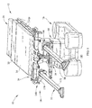
- a surgical support system 10 is shown in Figs.1-16 .
- the system 10 includes a surgical person support apparatus 12 and a hip distractor assembly 14 or surgical support device 14 coupled to the person support apparatus 12.
- the person support apparatus 12 is a surgical table 12 or operating room table 12 and includes a base 16, a lift system 18, and an upper frame 20 movably supported above the base.
- the upper frame 20 includes a head section 22, a seat section 24 and attachment rails 26.
- the upper frame 20 includes a foot section (not shown) that can be removed or moved out of the way when surgical equipment or accessories, such as, the hip distractor assembly 14 or a surgical spine system like the Allen® Spine System sold by Allen Medical Systems, are attached to the surgical table 12 as shown in Fig. 1 .
- the rails 26 extend along the sides of the sections 22 and 24 and are configured to provide a connection point where accessories and equipment can be attached to the surgical table 12.
- the hip distractor assembly 14 includes a table extension 28, an operative leg holder assembly 30 or leg support 30, a non-operative leg holder assembly 32 or leg support 32, and mounting brackets 34 or connector 34 as shown in Fig. 3 .
- the table extension 28 and the non-operative leg holder assembly 32 are configured to be coupled to the rails 26 via the brackets 34, and the operative leg holder assembly 30 is configured to be coupled to the table extension 28.
- the table extension 28 comprises a table coupling assembly 36, a connecting frame 38, a Y-shaped support frame assembly 40, and a platform 42 as shown in Figs. 1-3 .
- the connecting frame 38 is coupled between the table coupling assembly 36 and the support frame assembly 40 and includes an upper portion that cooperates with the table coupling assembly 36 to support the platform 42, and a lower portion that supports the support frame assembly 40 vertically below a portion of the platform 42.
- the platform 42 is substantially planar and includes a base portion 43a coupled to the table coupling assembly 36, and a hip support portion 43b extending from the base portion 43a that is coupled to the connecting frame 38.
- a support surface (not shown), such as, a foam pad, can be positioned on the platform 42.
- the hip support portion 43 is shaped to support a person's non-operative hip while allowing the person's operative hip to hang off the platform 42 unsupported.
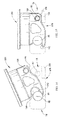
- the table coupling assembly 36 includes a length adjustable beam 44 and coupling assemblies 46 attached to the ends of the beam 44 as shown in Figs. 4-8 .
- the length adjusting beam 44 includes a telescoping arrangement that is configured to be adjusted to match the width of the person support apparatus 12, and locked in place with locking screw 45 when a desired width has been reached.
- the coupling assemblies 46 include a handle 48, a fork plate 50, and an insert 52.
- the handle 48 is coupled to the fork plate 50 and the fork plate 50 is coupled to the beam 44 by the insert 52.
- the fork plate 50 includes a guide slot 54 that is configured to engage the bracket 34 to help position the table extension 28 and maintain the engagement of the table extension 28 and the bracket 34.
- the fork plate 50 is shorter in length along the upper portion of the guide slot 54 to provide a lead in section that make it easier for a user to engage the bracket 34 with the guide slot 54.
- the insert 52 includes a base portion 56 and an extension 58 that extends from the base portion 56.
- the extension 58 includes a groove 60 and a curved portion 62 that are configured to engage the bracket 34 to help position the table extension 28 and maintain the engagement of the table extension 28 and the bracket 34.
- the support frame assembly 40 is generally Y-shaped and is configured to support the operative leg holder assembly 30.
- the support frame assembly 40 includes a frame 64 with a base 66 and angled arms 68, perineal post cones 70, a handle 72, connecting portion 74, and a mounting assembly 76 or connector enabling assembly 76 as shown in Figs. 4-7 .
- the support frame 40 supports a perineal post (not shown) that extends up through the opening 43c in the platform 42 on a perineal post cone 70.
- the base 66 is coupled to the connecting frame 38 and the angled arms 68 extend from the base 66 to form Y shape.
- the handle 72 is coupled between the angled arms 68 and is configured to be used to transport the table extension 28.
- the perineal post cones 70 are coupled to the angled arms 68 and are aligned with the openings 43c in the panel 42.
- the connecting portions 74 are located at the ends of the angled arms 68 and include an elongated slot 78 formed in the angled arm 68, a locking knob 80 positioned in a locking bore 82, and a mount bore 84 that a portion of the mounting assembly 76 moves within.
- a plug 86 can be inserted into an end of the mounting bore 84.
- the elongated slot 78 includes rounded opening edges 87a that helps guide the leg holder assembly into the slot 78, and an opening 87b in the bottom of the slot to help position and maintain the leg holder assembly in the slot 78.
- the mounting assembly 76 extends between the angled arms 68 and is configured to allow a user to select which connecting portion 74 they would like to attach the operative leg holder assembly 30 to.
- the mounting assembly 76 includes a shaft 88 and a handle 90 coupled to the shaft 88 as shown in Figs. 4-7 .
- the shaft 88 is sized such that the shaft 88 can only extend across the slot 78 of one of the connecting portions 74 so that only one operative leg holder assembly 30 can be supported by the table extension 28 at a time.
- the handle 90 is configured to move the shaft 88 and allow a user to select the connecting portion 74 they would like to attach the operative leg holder assembly 30 to.
- the shaft 88 is positioned within the mounting bores 84 and extends between the slots 78.
- the shaft 88 is sized so that the shaft 88 does not extend across the slot of either connecting portion 74 when the handle 90 is in a neutral position. In some contemplated embodiments, the shaft 88 is sized to extend across both slots 78 simultaneously, or two smaller shafts (not shown) are used and are positioned such that they each extend across one of the slots 78 so that more than one leg holder assembly can be supported by the table extension 28. In some contemplated embodiments, an indicator or a graphic (not shown) is used to indicate which way to move the handle 90 based on the patient's legs to be supported.
- the indicator or graphic is used to indicate which leg should be supported based on the current configuration of the device (i.e., left, right, none).
- the angled arms 68 include a pair of go/no-go openings 92 that show a portion of the mounting shaft 88 that may be colored red or green to indicate which connecting portion 74 the user can connect a leg holder assembly to.
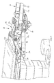
- the coupling bracket 34 includes a first side S1, a second side S2, a third side S3 extending between the first side S1 and the second side S2, a rail adapter portion 136, a guide pin 138, a locking knob 140, a table extension support 142, and a leg holder support portion 144 as shown in Figs. 8-12 .
- the rail adapter portion 136 extends from the first side S1 and is configured to engage the rail 26 and movably retain the bracket 34 on the rail 26.
- the rail adapter portion 136 includes an upper guide 146 that engages a portion of a top edge of the rail 26 and a lower guide 148 that engages a portion of the bottom edge of the rail 26.
- the guide 138 extends from the second side S2 and is configured to be engaged by table extension 28 and help align and support the table extension 28 when the table extension 26 is coupled to the bracket 34.
- the locking knob 140 extends from the second side S2 that is adjacent to the guide pin 138 and positioned in a locking opening 145 extending though the bracket 34 as shown in Figs. 8-12 .
- the locking knob 140 is configured to cooperate with the guide 146 and lower guide 148 to selectively engage the rail 26 to prevent the bracket 34 from moving with respect to the rail 26.
- the locking knob 140 is captured in the bracket 34 so that the locking knob 140 is prevented from falling off when the knob 140 is loosened to allow the bracket 34 to be removed from the rail 26.
- the table extension support 142 includes an insert engaging surface 150 with a protrusion 152 and a trigger 154.
- the insert engaging surface 150 is configured to be engaged by the extension 58 and the protrusion 152 is configured to engage the slot 60 in the insert 52 as shown in Fig. 8 .
- the trigger 154 is configured to selectively engage the curved portion 62 of the extension 58 to maintain the insert 52 from being removed from the table extension support 142 as shown in Figs. 8 and 12 .
- the trigger 154 is only included on one of the brackets 34 coupling the table extension 28 to the surgical table 12.
- the trigger 154 is rotatably coupled within a trigger recess 156 that is recessed from the third surface S3 and includes an angled surface 158 and a stop arm 160.
- the table extension 28 is being coupled to the bracket 34 and the extension 58 is moved into engagement with the insert engaging surface 150, the curved portion 62 of the insert 54 engages an angled side 158 of the trigger 154 and causes the trigger 154 to rotate from a first position, where the stop arm 160 engages the back of the trigger recess 156, to a second position, where the stop arm 160 is away from the back of the trigger recess 156.
- gravity causes the trigger 154 to rotate back to the first position to prevent the table extension 28 from accidentally or unintentionally being removed from the bracket 34.
- the trigger 154 must be manually moved from the first position to the second position by a user before the table extension 28 can be removed from the bracket 34. To do so, a user can use their thumb to pull the stop arm 160 away from the back of the trigger recess 156 and remove the insert 54 from the table extension support 142.
- the leg holder support portion 144 includes a hook shaped recess 162, a locking knob opening 164, and an anti-rotation pin opening 166 as shown in Figs. 8-12 .
- the hook shaped recess 162 is positioned generally vertically below the table extension support portion 142 and is shaped to help guide the coupling pin 176 of the non-operative leg coupling assembly 168 toward the base of the hook shaped recess 162.
- the anti-rotation pin opening 166 is configured to receive an anti-rotation pin (not shown) that engages the recessed groove 180 in the coupling assembly 168 and prevents the leg holder assembly 32 from rotating when the coupling pin 60 is located at the base of the hook shaped recess 54.
- leg holder assembly 32 By preventing rotation of the non-operative leg holder assembly 32, a user can attach the leg holder assembly 32 to the bracket 34 and secure the leg holder assembly 32 with the leg holder locking knob 178 without having to support the leg holder assembly 32 themselves to maintain alignment of the locking knob opening 164 and the leg holder locking knob 178.
- the non-operative leg holder assembly 32 includes a non-operative leg coupling assembly 168, a first spar 170 or adapter 170, and a second spar 172 as shown in Figs. 1-3 and 12 .
- the coupling assembly 168 is generally U-shaped bracket 174 with the coupling pin 176 extending between the sides of the bracket 174, and the leg holder locking knob 178 engaging a locking opening 179 passing through one side of the bracket 174.
- the bracket 174 includes a recessed groove 180 configured to engage the anti-rotation pin extending from the bracket 34.
- the coupling assembly 168 is attached to the first spar 170 and the first spar 170 is rotatably attached to the second spar 172.
- the second spar 172 is configured to support a foot holding device (not shown).
- the first spar 170 is pivotably and removably coupled to the second spar 172 at a joint.
- the user couples the first spar 170 to the second spar 172 in a first orientation when the assembly 32 is connected to one side of the person support apparatus 12, i.e., the left side, and disconnects, flips over, and reconnects the first spar 170 to the second spar 172 in a second orientation when the user desires to connect the assembly 32 to the other side, i.e., the right side, of the person support apparatus 12.
- the operative leg holder assembly 30 includes a spar 182 and a connector 184 coupled to the end of the spar 182 as shown in Figs. 1-2 and 13-16 .
- the connector 184 includes a hook end 186, a locking bore 188, and a mounting end 190 opposite the hook end 186.
- the hook end 186 is configured to engage the mounting shaft 88 when the operative leg holder assembly 30 is attached to the connecting portion 74 of the table extension 28.
- the hook end 186 includes an angled end 192 that helps guide the mounting shaft 88 toward the base of the hook 186.
- the connector 184 is shaped such that when the hook end 186 engages the mounting shaft 88, a portion of the connector 184 extends through the opening 87b in the bottom of the slot 78 and the mounting end 190 engages the mounting portion 194 of the slot 78 to help position the connector 184 in the slot 78 such that the locking bore 188 and the locking bore 82 are substantially aligned so the locking knob 80 can be tightened to secure the leg holder assembly 30 to the table extension 28 as shown in Fig 15 .
- the mounting end 190 helps maintain the engagement of the hook end 186 and the mounting shaft 88 so that the leg holder assembly 30 is supported by the table extension 28 and the user does not need to support the leg holder assembly 30 while attempting to secure it in place with the locking knob 80. If a user attempted to mount the leg holder assembly 30 to a connecting portion 74 that the mounting shaft 88 did not extend across, the leg holder assembly 30 would not be fully supported by the table extension 28 because the connector 184 would be allowed to rotate in the slot 78 as shown in Fig. 16 , due to the rotational moment caused by the weight of the leg holder assembly 30.
- a surgical support system comprises a surgical table; a first leg support assembly coupled to the surgical table; a second leg support assembly; and a surgical table extension coupled to the surgical table and including a first connector and a second connector and a connector enabling assembly configured to selectively enable the second leg support assembly to be coupled to one of the first connector and the second connector.
- a surgical support system comprises a surgical table; a leg support assembly including a leg support connector with a hook shaped portion; and a surgical table extension coupled to the surgical table and including a first connector defining a first slot with a first shaft extending across the first slot and a second connector defining a second slot with a second shaft extending across the second slot, wherein the hook shaped portion is configured to engage one of the first shaft and the second shaft when the leg support connector is inserted into one of the first slot and the second slot, respectively.
- a bracket for coupling at least one surgical table accessory to a surgical table comprises a rail coupling portion; a first accessory retaining portion; and a second accessory retaining portion positioned vertically below the first retaining portion.
- a surgical table extension comprises a surgical table frame coupled to a surgical table by a connecting assembly; a first accessory connector; a second accessory connector; and an accessory connector enabling assembly configured to be moved between a first position and a second position, wherein the first accessory connector is configured to receive and retain an accessory when the accessory connector enabling assembly is in the first position and the second accessory connector is configured to receive and retain an accessory when the accessory connector enabling assembly is in the second position.
Landscapes
- Health & Medical Sciences (AREA)
- Engineering & Computer Science (AREA)
- Biomedical Technology (AREA)
- Life Sciences & Earth Sciences (AREA)
- Animal Behavior & Ethology (AREA)
- General Health & Medical Sciences (AREA)
- Public Health (AREA)
- Veterinary Medicine (AREA)
- Accommodation For Nursing Or Treatment Tables (AREA)
Priority Applications (1)
| Application Number | Priority Date | Filing Date | Title |
|---|---|---|---|
| EP17151791.5A EP3175833A1 (de) | 2012-09-07 | 2013-09-05 | Chirurgisches unterstützungssystem |
Applications Claiming Priority (3)
| Application Number | Priority Date | Filing Date | Title |
|---|---|---|---|
| US201261698547P | 2012-09-07 | 2012-09-07 | |
| US13/799,251 US9730851B2 (en) | 2012-09-07 | 2013-03-13 | Surgical support system |
| EP13183197.6A EP2705822B1 (de) | 2012-09-07 | 2013-09-05 | Chirurgisches Unterstützungssystem |
Related Parent Applications (1)
| Application Number | Title | Priority Date | Filing Date |
|---|---|---|---|
| EP13183197.6A Division EP2705822B1 (de) | 2012-09-07 | 2013-09-05 | Chirurgisches Unterstützungssystem |
Related Child Applications (1)
| Application Number | Title | Priority Date | Filing Date |
|---|---|---|---|
| EP17151791.5A Division EP3175833A1 (de) | 2012-09-07 | 2013-09-05 | Chirurgisches unterstützungssystem |
Publications (2)
| Publication Number | Publication Date |
|---|---|
| EP2932952A1 true EP2932952A1 (de) | 2015-10-21 |
| EP2932952B1 EP2932952B1 (de) | 2017-01-25 |
Family
ID=49165530
Family Applications (3)
| Application Number | Title | Priority Date | Filing Date |
|---|---|---|---|
| EP15169611.9A Active EP2932952B1 (de) | 2012-09-07 | 2013-09-05 | Chirurgisches unterstützungssystem |
| EP13183197.6A Active EP2705822B1 (de) | 2012-09-07 | 2013-09-05 | Chirurgisches Unterstützungssystem |
| EP17151791.5A Withdrawn EP3175833A1 (de) | 2012-09-07 | 2013-09-05 | Chirurgisches unterstützungssystem |
Family Applications After (2)
| Application Number | Title | Priority Date | Filing Date |
|---|---|---|---|
| EP13183197.6A Active EP2705822B1 (de) | 2012-09-07 | 2013-09-05 | Chirurgisches Unterstützungssystem |
| EP17151791.5A Withdrawn EP3175833A1 (de) | 2012-09-07 | 2013-09-05 | Chirurgisches unterstützungssystem |
Country Status (2)
| Country | Link |
|---|---|
| US (2) | US9730851B2 (de) |
| EP (3) | EP2932952B1 (de) |
Families Citing this family (14)
| Publication number | Priority date | Publication date | Assignee | Title |
|---|---|---|---|---|
| US9901503B2 (en) | 2008-03-13 | 2018-02-27 | Optimedica Corporation | Mobile patient bed |
| US9730851B2 (en) | 2012-09-07 | 2017-08-15 | Allen Medical Systems, Inc. | Surgical support system |
| EP2873405B1 (de) * | 2013-11-18 | 2016-05-18 | Schaerer Medical Management AG | Modularer operationstisch |
| KR101844217B1 (ko) * | 2014-01-13 | 2018-04-03 | 페르노-와싱턴, 인코포레이티드. | 구급 간이침대들에 대한 부속 클램프 |
| DE102016216996A1 (de) * | 2016-09-07 | 2018-03-08 | Trumpf Medizin Systeme Gmbh + Co. Kg | Verbindungseinrichtung und Verfahren zum Entriegeln der Verbindungseinrichtung |
| CN106726311B (zh) * | 2017-02-17 | 2018-10-26 | 广州中医药大学第一附属医院 | 一种可调角度的髋人字石膏矫形床 |
| US11234885B2 (en) * | 2018-02-20 | 2022-02-01 | Allen Medical Systems, Inc. | Adjustable lithotomy positioning apparatus with a limb rest |
| BE1026472B1 (nl) * | 2018-07-16 | 2020-02-10 | Orfit Ind | Eerste rompelement van een verbindingssamenstel voor het losneembaar verbinden van een uitbreidingspaneel met een patiëntondersteuningspaneel dat gemonteerd is op een voetstuk |
| CO2019000131A1 (es) * | 2019-01-09 | 2019-02-19 | Winkler Carlos Alfonso Prada | Tractor y posicionador de miembros inferiores para cirugía de osteosíntesis y artroscopia en cadera |
| US11730560B2 (en) | 2019-07-12 | 2023-08-22 | Stuckenbrock Medizintechnik Gmbh | Fast-action clamping device with locking mechanism, and surgical device |
| US10729577B1 (en) * | 2019-09-11 | 2020-08-04 | King Saud University | Hip spica cast application device |
| CN211356501U (zh) * | 2019-11-05 | 2020-08-28 | 通快医疗系统两合公司 | 手术台扩展单元的支撑板连接装置及手术台 |
| US11890118B2 (en) | 2021-03-24 | 2024-02-06 | Stryker Corporation | Patient support apparatus with support assembly for medical device |
| CN113855452A (zh) * | 2021-10-22 | 2021-12-31 | 西安大兴医院 | 一种内分泌科用多功能检查台 |
Citations (3)
| Publication number | Priority date | Publication date | Assignee | Title |
|---|---|---|---|---|
| US5056535A (en) * | 1990-01-22 | 1991-10-15 | Leonard Medical | Varus and valgus leg manipulator |
| US20090307845A1 (en) * | 2008-06-13 | 2009-12-17 | Rao Sudhir B | Shoulder surgery attachment for a surgical table |
| US20110099720A1 (en) * | 2009-09-30 | 2011-05-05 | Maquet Gmbh & Co. Kg | Adapter for connecting at least one accessory device to an operating table |
Family Cites Families (185)
| Publication number | Priority date | Publication date | Assignee | Title |
|---|---|---|---|---|
| US1160451A (en) | 1914-04-06 | 1915-11-16 | Charles H Sanford | Combined fracture and orthopedic operating-table. |
| US1501120A (en) | 1921-03-17 | 1924-07-15 | Eduard H Karrer | Traction apparatus |
| US3509876A (en) | 1966-10-18 | 1970-05-05 | Stierlen Werke Ag | Apparatus for the treatment of bone fractures |
| BR6899660D0 (pt) | 1968-06-06 | 1973-03-13 | A Staib | Aperfeicoamentos em dispositivos de tracao para mesas ortopedicas |
| US3745996A (en) | 1971-02-19 | 1973-07-17 | Berivon Co | Apparatus for the reduction of bone fractures |
| US3982742A (en) | 1975-11-17 | 1976-09-28 | Ford John L | Medical stirrups |
| GB1596036A (en) | 1977-04-01 | 1981-08-19 | Nat Res Dev | Surgical apparatus |
| US4180062A (en) * | 1978-04-10 | 1979-12-25 | James Alberti | Portable childbirth chair with electronic monitoring apparatus |
| US4185813A (en) | 1978-05-17 | 1980-01-29 | Spann Donald C | Surgical body positioner |
| US4471952A (en) | 1979-04-26 | 1984-09-18 | Span-America Medical Systems, Inc. | Surgical body positioner and disposable topper |
| US4252306A (en) | 1979-09-13 | 1981-02-24 | Lanny L. Johnson | Device for clamping body parts |
| US4766892A (en) | 1980-07-25 | 1988-08-30 | Gary Kreitman | Limb restraint |
| US4373709A (en) | 1980-09-24 | 1983-02-15 | Whitt Everett D | Surgical limb holder |
| US4407277A (en) | 1980-10-27 | 1983-10-04 | Ellison Arthur E | Surgical apparatus |
| US4418900A (en) | 1981-03-03 | 1983-12-06 | Ricke Theodore D | Corpse positioning system |
| US4428571A (en) | 1981-05-15 | 1984-01-31 | Sugarman Edward D | Limb positioning device |
| US4579324A (en) | 1981-05-27 | 1986-04-01 | Mcconnell Bernard E | Universal extremity positioner |
| US4367869A (en) | 1981-09-10 | 1983-01-11 | Dailey Thomas H | Stirrup attachment for surgical table |
| US4872656A (en) | 1981-12-21 | 1989-10-10 | American Sterilizer Company | Orthopedic table with movable upper body and sacrum supports |
| US4443005A (en) | 1982-09-09 | 1984-04-17 | Edward D. Sugarman | Foot support device |
| US4526355A (en) | 1982-09-29 | 1985-07-02 | Moore Robert R | Arthroscopic leg holder |
| US4545573A (en) | 1983-03-03 | 1985-10-08 | Saginaw Automation & Machine, Inc. | Surgical leg clamp |
| US4732145A (en) | 1984-09-14 | 1988-03-22 | Latham Philip B | Restraining device for spinal taps |
| US5015251A (en) | 1984-11-30 | 1991-05-14 | Alimed, Inc. | Medical fastener strap |
| US4620698A (en) | 1985-03-04 | 1986-11-04 | Professional Medical Products, Inc. | Orthopedic support device |
| US4782827A (en) | 1985-12-05 | 1988-11-08 | Bernard Paratte | Orthopedic apparatus |
| FR2596637B1 (fr) | 1986-04-03 | 1988-07-15 | Marzet Aubry | Dispositif de traction pour tables d'operations et appareillages de chirurgie orthopedique |
| US4681309A (en) | 1986-05-12 | 1987-07-21 | Paula Lechner | Surgical prep block and surgical assist block |
| US4827496A (en) | 1986-06-23 | 1989-05-02 | M. C. Johnson Co., Inc. | Leg and ankle holder for assisting medical and radiological professionals in X-ray examination and filming of the ankle and foot structure |
| FR2621245B1 (fr) | 1987-10-05 | 1997-10-24 | Tasserit Ets | Table d'operation orthopedique pour membres et notamment pour membres inferieurs |
| US4809687A (en) | 1987-12-30 | 1989-03-07 | Edgewater Medical Systems | Medical stirrup |
| US4964400A (en) | 1988-04-19 | 1990-10-23 | Lincoln Mills, Inc. | Surgical limb supporting apparatus with tension measuring device |
| US5001739A (en) | 1988-06-06 | 1991-03-19 | Fischer William B | Contoured surgical table |
| US4886258A (en) | 1988-08-24 | 1989-12-12 | Scott James W | Well leg operative support |
| US4913413A (en) | 1989-06-09 | 1990-04-03 | Faro Medical Technologies Inc. | Universal leg holder |
| US5042508A (en) | 1989-10-23 | 1991-08-27 | Richard Patricia A | Fractured limb stabilizing device |
| US5052378A (en) | 1989-11-03 | 1991-10-01 | Glacier Cross, Inc. | Portable traction apparatus |
| US5025802A (en) | 1990-02-08 | 1991-06-25 | Lincoln Mills, Inc. | Surgical holding apparatus for distracting ankle |
| US5369827A (en) | 1990-02-21 | 1994-12-06 | Mend Technologies, Inc. | Medical stirrups |
| US5097847A (en) | 1990-03-19 | 1992-03-24 | Mikhail Michael W E | Extremity sheet and leg holder combination |
| US6017006A (en) | 1990-10-04 | 2000-01-25 | Alimed, Inc. | Keyboard wrist rest |
| USD336898S (en) | 1991-07-15 | 1993-06-29 | Alimed, Inc. | Wrist rest for a computer |
| US5514143A (en) | 1991-11-27 | 1996-05-07 | Apogee Medical Products, Inc. | Apparatus and method for use during surgery |
| US5542423A (en) * | 1991-12-04 | 1996-08-06 | Apogee Medical Products, Inc. | Indexing assembly for joint imaging |
| US5290220A (en) | 1992-03-16 | 1994-03-01 | Guhl James F | Non-invasive distraction system for ankle arthroscopy |
| US5549707A (en) | 1994-01-18 | 1996-08-27 | Contour Fabricators, Inc. | Fluid collection apparatus |
| US5658315A (en) | 1994-02-23 | 1997-08-19 | Orthopedic Systems, Inc. | Apparatus and method for lower limb traction |
| US5462551A (en) | 1994-04-04 | 1995-10-31 | Innovative Medical Products Inc. | Knee positioner |
| US5582379A (en) | 1994-06-24 | 1996-12-10 | Allen Medical Systems | Adjustable limb support system |
| US5515562A (en) | 1994-06-24 | 1996-05-14 | Health Care Solutions, Inc. | Sacral and perineal pads |
| US5608934A (en) | 1994-10-06 | 1997-03-11 | Smith & Nephew Dyonics, Inc. | Hip distractor |
| US5645079A (en) | 1994-12-02 | 1997-07-08 | Zahiri; Hormoz | Apparatus for mechanically holding, maneuvering and maintaining a body part of a patient during orthopedic surgery |
| US5511255A (en) | 1995-01-24 | 1996-04-30 | Schuerch; Peter | Medical patient shifting device and method of use |
| US5661859A (en) * | 1995-10-20 | 1997-09-02 | Midmark Corporation | Shoulder arthoscopy attachment |
| US5830108A (en) | 1996-01-03 | 1998-11-03 | Alimed, Inc. | Contracture means and method |
| IL117345A0 (en) | 1996-03-04 | 1996-07-23 | Gotfried Yechiel | Height-adjustable support for lower-limb operations |
| US5918330A (en) | 1996-08-14 | 1999-07-06 | Allen Medical Systems, Inc. | Ratchet mechanism for booted surgical stirrup |
| US6012456A (en) | 1997-02-14 | 2000-01-11 | Schuerch; Peter | Arthroscopic leg holder |
| US5802641A (en) | 1997-03-07 | 1998-09-08 | Amatech Corporation | Leg holder system for simultaneous positioning in the abduction and lithotomy dimensions |
| US5961085A (en) | 1997-04-04 | 1999-10-05 | Amatech Corporation | Locking-cylinder supported surgical boot |
| US5799349A (en) | 1997-11-07 | 1998-09-01 | Petersen; Thomas D. | Surgical knee holder |
| US6295671B1 (en) | 1998-03-06 | 2001-10-02 | Ohio Medical Instrument Company, Inc. | Medical surgical table including interchangeable orthopedic attachment and scanning table |
| US6378149B1 (en) | 1999-01-25 | 2002-04-30 | Steris Inc | Radiolucent split-leg accessory for a surgical table |
| EP1152727B1 (de) | 1999-02-11 | 2005-01-12 | Schaerer Mayfield USA, Inc. | Mit scharnieren versehener adaptor für eine röntgenstrahldurchlässige tischverlängerung |
| US6408464B1 (en) * | 1999-08-23 | 2002-06-25 | Hill-Rom Services, Inc. | Birthing bed foot section attachment mechanism |
| US6470520B1 (en) * | 1999-08-23 | 2002-10-29 | Hill-Rom Services, Inc. | Bed section attachment mechanism |
| US6757924B2 (en) * | 1999-08-23 | 2004-07-06 | Hill-Rom Services, Inc. | Bed having a removable foot section |
| US6438777B1 (en) | 2000-01-27 | 2002-08-27 | Tri-Medics, Inc. | Surgical supporting device |
| US6289537B1 (en) | 2000-02-09 | 2001-09-18 | Stryker Corporation | Patient support |
| US6295672B1 (en) | 2000-03-03 | 2001-10-02 | Robert E. Vassallo, Jr. | Removable spine board foot support |
| US6813788B2 (en) | 2000-04-06 | 2004-11-09 | Schaerer Mayfield Usa, Inc. | Variable length radiolucent surgical table extension |
| US6306146B1 (en) | 2000-04-06 | 2001-10-23 | Ohio Medical Instrument Company, Inc. | Surgical instrument support and method |
| DE10022937B4 (de) | 2000-05-11 | 2005-02-24 | Schaerer Mayfield USA, Inc., Cincinnati | Sensoranordnung zur Erfassung von Lage- und Positionsveränderungen eines Probanden in einem Neuronavigationssystem |
| CA2314710A1 (en) | 2000-07-28 | 2002-01-28 | Tenet Medical Engineering Inc. | Releasable lockable joint apparatus |
| CA2314758A1 (en) | 2000-07-28 | 2002-01-28 | Tenet Medical Engineering Inc. | Releasable lockable re-positionable arm like support apparatus |
| US7175900B2 (en) | 2000-07-31 | 2007-02-13 | Contour Fabricators, Inc. | Reinforced pad and method of making |
| US6704959B2 (en) | 2001-08-13 | 2004-03-16 | Peter Schuerch | Adjustable position limb support for surgical tables |
| DE10147588B4 (de) | 2001-09-27 | 2005-03-17 | Maquet Gmbh & Co. Kg | Befestigungskloben zur Halterung von Gegenständen an einer Profilschiene |
| DE10151398B4 (de) | 2001-10-18 | 2005-03-17 | Schaerer Mayfield USA, Inc., Cincinnati | Vorrichtung zur Adaption chirurgischer Instrumente als Zeigereinrichtung |
| US6804846B2 (en) | 2002-03-14 | 2004-10-19 | Peter Schuerch | Shoulder arthroscopy chair |
| US6698044B2 (en) | 2002-03-30 | 2004-03-02 | Saul P. Greenfield | Pediatric stirrup device and method |
| US6723036B2 (en) | 2002-06-19 | 2004-04-20 | Contour Fabricators, Inc. | Methods and apparatus for folding sheet material |
| DE10253906A1 (de) | 2002-11-19 | 2004-06-03 | Maquet Gmbh & Co. Kg | Beinplattenanordnung für Operationstische |
| US7026940B2 (en) | 2003-01-02 | 2006-04-11 | Alimed, Inc. | Chair back monitoring device |
| US6826794B2 (en) | 2003-01-14 | 2004-12-07 | Surgical Devices, Inc. | Apparatus and method for positioning a patient during surgery |
| WO2004071320A1 (en) | 2003-02-10 | 2004-08-26 | Integra Ohio, Inc. | Radiolucent skull clamp with removable pin load applicator |
| US20070015960A1 (en) | 2003-02-28 | 2007-01-18 | Schaerer Mayfield Technologies Gmbh | Device for localizing, influencing and guiding of tracking bodies, and method for operating a marking device |
| US7544007B2 (en) | 2003-03-21 | 2009-06-09 | Integra Lifesciences Corporation | Swivel adapter and base unit handle |
| US6869194B2 (en) | 2003-03-24 | 2005-03-22 | Contour Fabricators, Inc. | Sterilizable drape for ophthalmoscopic lens |
| DE10327237A1 (de) | 2003-06-17 | 2005-01-13 | Trumpf Medizin Systeme Gmbh + Co. Kg | Elektrochirurgisches Instrument für ein Endoskop |
| DE10336303A1 (de) | 2003-07-31 | 2005-03-03 | Trumpf Medizin Systeme Gmbh | Verfahren zum Transport einer Patiententragplatte und Transportvorrichtung zur Durchführung des Verfahrens |
| US7534270B2 (en) | 2003-09-03 | 2009-05-19 | Integra Lifesciences Corporation | Modular total ankle prosthesis apparatuses and methods |
| US7125379B2 (en) | 2003-09-19 | 2006-10-24 | Minnesota Scientific, Inc. | Surgical support arm docking apparatus |
| US7210180B2 (en) * | 2003-10-20 | 2007-05-01 | Malcolm Roger J | Surgical table width extension and angularly orientable attachment |
| US6876503B1 (en) | 2003-10-28 | 2005-04-05 | Contour Fabricators, Inc. | Microscope drape lens protective cover assembly |
| DE10352707A1 (de) | 2003-11-12 | 2005-06-16 | Maquet Gmbh & Co. Kg | Fußteil für einen Operationstisch |
| DE502004003272D1 (de) | 2004-02-28 | 2007-05-03 | Trumpf Kreuzer Med Sys Gmbh | Operationsleuchte |
| EP1568938B1 (de) | 2004-02-28 | 2006-09-27 | TRUMPF Kreuzer Medizin Systeme GmbH + Co. KG | Operationsleuchte |
| US7730563B1 (en) | 2004-03-29 | 2010-06-08 | Frederick Sklar | Head support and stabilization system |
| FR2871050B1 (fr) | 2004-06-08 | 2006-08-11 | Medacta Int Sa | Systeme d'accouplement et commande d'un moyen d'allongement d'un patient a operer |
| US7082631B2 (en) | 2004-07-22 | 2006-08-01 | Contour Fabricators, Inc. | Imaging table protective cover |
| US7600281B2 (en) * | 2004-11-10 | 2009-10-13 | Allen Medical Systems, Inc. | Body support apparatus for spinal surgery |
| US7520007B2 (en) * | 2004-11-10 | 2009-04-21 | Allen Medical Systems, Inc. | Accessory rail clamp with latch and lock mechanisms |
| US7669262B2 (en) * | 2004-11-10 | 2010-03-02 | Allen Medical Systems, Inc. | Accessory frame for spinal surgery |
| US7412739B2 (en) * | 2004-12-03 | 2008-08-19 | Stryker Corporation | Patient support apparatus with removable foot section |
| US7311441B2 (en) | 2004-12-21 | 2007-12-25 | Contour Fabricators, Inc. | Pouch construction |
| US7458117B2 (en) | 2004-12-23 | 2008-12-02 | Contour Fabricators, Inc. | Protective cover and patient security apparatus |
| US7739762B2 (en) | 2007-10-22 | 2010-06-22 | Mizuho Orthopedic Systems, Inc. | Surgery table apparatus |
| US7731141B2 (en) | 2005-04-06 | 2010-06-08 | Peter Schuerch | Surgical appliance post clamp for surgical tables |
| US7243654B2 (en) | 2005-04-08 | 2007-07-17 | Peter Schuerch | Adjustable position limb support for surgical tables |
| WO2006116047A2 (en) | 2005-04-22 | 2006-11-02 | Hutchinson Technology Incorporated | A method for mounting a head slider |
| US7331071B1 (en) | 2005-05-11 | 2008-02-19 | Julian Cherubini | Method and apparatus for detecting the presence or absence of a person on a flexible support |
| JP4468857B2 (ja) | 2005-05-17 | 2010-05-26 | 株式会社小糸製作所 | 車両用照明灯具 |
| DE102005036275A1 (de) | 2005-08-02 | 2007-02-08 | Berchtold Holding Gmbh | Operationsleuchte |
| PL1750052T3 (pl) | 2005-08-06 | 2011-04-29 | Trumpf Medizin Systeme Gmbh & Co Kg | Lampa operacyjna |
| DE102005053754A1 (de) | 2005-11-10 | 2007-05-16 | Maquet Gmbh & Co Kg | Einrichtung zum Verstellen der Liegefläche eines Operationstisches |
| DE102005053753A1 (de) | 2005-11-10 | 2007-05-16 | Maquet Gmbh & Co Kg | Hydraulische Säulenklemmung |
| DE102005054222A1 (de) | 2005-11-14 | 2007-05-16 | Maquet Gmbh & Co Kg | Operationstisch |
| DE102005054174A1 (de) * | 2005-11-14 | 2007-05-16 | Maquet Gmbh & Co Kg | Patientenlagerfläche für einen Operationstisch |
| DE102005054175A1 (de) * | 2005-11-14 | 2007-05-16 | Maquet Gmbh & Co Kg | Gelenkanordnung zur Verbindung zweier Segmente einer Patientenlagerfläche |
| DE102005054224A1 (de) | 2005-11-14 | 2007-05-16 | Maquet Gmbh & Co Kg | Patientenlagersystem |
| WO2007054367A1 (de) | 2005-11-14 | 2007-05-18 | Trumpf Medizin Systeme Gmbh + Co. Kg | Operationsleuchtensystem |
| DE102005054221A1 (de) | 2005-11-14 | 2007-05-16 | Maquet Gmbh & Co Kg | Patientenlagersystem |
| DE102005054223A1 (de) | 2005-11-14 | 2007-05-16 | Maquet Gmbh & Co Kg | Einrichtung zum Verstellen eines Operationstisches |
| US7832401B2 (en) | 2005-11-30 | 2010-11-16 | Smith & Nephew, Inc. | Hip distraction |
| US7947006B2 (en) * | 2005-11-30 | 2011-05-24 | Smith & Nephew, Inc. | Hip distraction |
| US7294114B1 (en) | 2006-01-19 | 2007-11-13 | Alimed, Inc. | Foot orthotic for safe ambulation |
| DE102006014003A1 (de) | 2006-03-27 | 2007-10-04 | Berchtold Holding Gmbh | Medizinische Leuchte |
| US20070272808A1 (en) | 2006-05-25 | 2007-11-29 | Peter Schuerch | Multi-dimensional adjustable head support for shoulder arthroscopy chairs |
| US7520004B2 (en) | 2006-07-25 | 2009-04-21 | Contour Fabricators, Inc. | Combined cushion and protective cover and methods of forming |
| US7552492B2 (en) | 2006-09-22 | 2009-06-30 | Integra Lifesciences Corporation | Head support base unit with multi-directional capability |
| EP1911401B1 (de) | 2006-10-10 | 2012-06-06 | TRUMPF Medizin Systeme GmbH + Co. KG | Plattensegment für eine mehrteilige Patientenlagerungsplatte und einen OP-Tisch |
| DE102006059733A1 (de) | 2006-12-18 | 2008-06-19 | Maquet Gmbh & Co. Kg | Lösbare Anbringung eines Zubehörs an einem Operationstisch |
| US20080163427A1 (en) | 2007-01-04 | 2008-07-10 | Contour Fabricators, Inc. | Adjustable body positioning device |
| US20090250073A1 (en) | 2007-06-29 | 2009-10-08 | Mizuho Osi | Patient Arm Pad with Adjustment |
| US20090026901A1 (en) | 2007-07-26 | 2009-01-29 | Berchtold Holding Gmbh | Medical Servicing System |
| DE502007007063D1 (de) | 2007-08-03 | 2011-06-09 | Trumpf Medizin Systeme Gmbh & Co Kg | Operationstisch |
| EP2026577A1 (de) | 2007-08-08 | 2009-02-18 | TRUMPF Medizin Systeme GmbH + Co. KG | Verfahren zur Übertragung eines Videosignals einer an einem OP-Leuchtensystem angeordneten Kamera sowie OP-Leuchtensystem |
| DE102007060808A1 (de) | 2007-09-01 | 2009-03-05 | Maquet Gmbh & Co. Kg | Anordnung und Verfahren zum Bereitstellen mindestens einer Bedienfunktion einer Fernbedienung zum Bedienen eines Gerätes |
| US7999414B2 (en) | 2007-09-01 | 2011-08-16 | Maquet Gmbh & Co. Kg | Apparatus and method for wireless energy and/or data transmission between a source device and at least one target device |
| DE102007043431A1 (de) | 2007-09-12 | 2009-03-19 | Maquet Gmbh & Co. Kg | Transportwagen für die Patientenlagerfläche eines Operationstisches |
| DE102007045456A1 (de) | 2007-09-24 | 2009-04-09 | Trumpf Kreuzer Medizin Systeme Gmbh + Co. Kg | Beleuchtungsvorrichtung für eine medizinische Versorgungseinheit |
| DE102007053327A1 (de) | 2007-11-08 | 2009-05-14 | Trumpf Medizin Systeme Gmbh + Co.Kg | Medizinische Versorgungseinheit zur Stromversorgung und Datenübertragung bei medizinischen Apparaten |
| WO2009062545A1 (en) | 2007-11-13 | 2009-05-22 | Schaerer Mayfield Medical Ag | Modular device for positioning and immobilisation of a patient's body for surgical operations and corresponding operating table |
| EP2063309B1 (de) | 2007-11-13 | 2012-09-26 | TRUMPF Medizin Systeme GmbH + Co. KG | Verfahren zum Ausleuchten einer Operationsstelle |
| DE102007055463A1 (de) | 2007-11-13 | 2009-05-28 | Trumpf Medizin Systeme Gmbh | Operationstischsäule |
| DE102007055465A1 (de) | 2007-11-13 | 2009-05-20 | Trumpf Medizin Systeme Gmbh | Fernbedienung für eine Vorrichtung zur Lagerung eines Patienten |
| US20090141853A1 (en) | 2007-11-30 | 2009-06-04 | Veronica Crews | Protective shield for ct scanning machine |
| US7870624B1 (en) | 2007-12-03 | 2011-01-18 | Winston Mary H | Height-adjustable examining table |
| DE102007060810A1 (de) | 2007-12-18 | 2009-06-25 | Maquet Gmbh & Co. Kg | Anordnung, System und Verfahren zur drahtlosen Steuerung eines Gerätes |
| US8118739B2 (en) | 2008-01-23 | 2012-02-21 | Mizuho America | Endonasal speculum |
| US7861720B1 (en) | 2008-02-21 | 2011-01-04 | Mizuho Orthopedic Systems, Inc | Axillary support cushion device |
| DE102008011129A1 (de) | 2008-02-26 | 2009-08-27 | Berchtold Holding Gmbh | Aufhängung |
| US7918813B2 (en) | 2008-03-05 | 2011-04-05 | Alimed, Inc. | Flexibly adjustable dorsal splint |
| DE102008014128A1 (de) | 2008-03-13 | 2009-09-17 | Berchtold Holding Gmbh | Operationsleuchte |
| US8856809B2 (en) | 2008-03-19 | 2014-10-07 | International Business Machines Corporation | Controlling navigation of application logic using annotated application code |
| DE102008015210A1 (de) | 2008-03-20 | 2009-09-24 | Maquet Gmbh & Co. Kg | Stativ zur Halterung und Positionierung einer Nutzlast im Raum |
| US8256047B2 (en) * | 2008-04-03 | 2012-09-04 | Klemm Kurt W | Combination treatment device and an anterior support device |
| EP2136128B1 (de) | 2008-06-20 | 2011-01-19 | TRUMPF Medizin Systeme GmbH + Co. KG | Operationsleuchte |
| ATE477452T1 (de) | 2008-06-20 | 2010-08-15 | Trumpf Medizin Systeme Gmbh & Co Kg | Operationsleuchte mit aufhängevorrichtung |
| PL2136126T3 (pl) | 2008-06-20 | 2011-02-28 | Trumpf Medizin Systeme Gmbh & Co Kg | Lampa operacyjna |
| PL2136127T3 (pl) | 2008-06-20 | 2011-04-29 | Trumpf Medizin Systeme Gmbh & Co Kg | Lampa operacyjna z oświetlanymi uchwytami |
| DE202008008574U1 (de) | 2008-06-25 | 2008-08-28 | Maquet Gmbh & Co. Kg | Verkleidung einer höhenverstellbaren Stützsäule |
| USD606832S1 (en) | 2008-07-08 | 2009-12-29 | Alimed, Inc. | Square post surgical table clamp |
| USD604422S1 (en) | 2008-07-30 | 2009-11-17 | Trumpf Medizin Systeme Gmbh | Patient-supporting panel of an operating table |
| USD604421S1 (en) | 2008-07-30 | 2009-11-17 | Trumpf Medizin Systeme Gmbh | Patient-supporting panel of an operating table |
| USD602162S1 (en) | 2008-07-30 | 2009-10-13 | Trumpf Medizin Systeme Gmbh | Height adjustable column for an operating table or the like |
| US8051515B1 (en) * | 2008-08-12 | 2011-11-08 | Bob Kring | Surgical bed clamp apparatus |
| US8621692B1 (en) * | 2008-08-12 | 2014-01-07 | Bob Kring | Surgical bed clamp apparatus |
| DE102008039772A1 (de) | 2008-08-26 | 2010-03-04 | Berchtold Holding Gmbh | Handgriff |
| US20100242177A1 (en) | 2008-09-30 | 2010-09-30 | Composite Manufacturing, Inc. | Padded patient immobilizer for surgery tables |
| EP2169965B1 (de) | 2008-09-30 | 2011-09-21 | TRUMPF Medizin Systeme GmbH + Co. KG | System mit einer Operationsleuchte, einer Kamera und einem Monitor |
| DE102008057336A1 (de) | 2008-11-14 | 2010-06-02 | Haindl, Hans, Dr. | Klemmhalterung |
| US8615827B2 (en) * | 2009-03-03 | 2013-12-31 | Hill-Rom Services, Inc. | Person-support apparatus with movable portions |
| US8332977B2 (en) | 2009-03-03 | 2012-12-18 | Gwenventions, Llc | Bedside medical examination device |
| US9681924B2 (en) | 2009-03-31 | 2017-06-20 | Sean Rolfes | Skull clamp with improved positionability and cleaning capability |
| DE102009018270A1 (de) | 2009-04-21 | 2010-10-28 | Berchtold Holding Gmbh | Operationstisch |
| PL2248504T3 (pl) | 2009-05-07 | 2014-05-30 | Trumpf Medizin Systeme Gmbh & Co Kg | Medyczna jednostka zasilająca z wbudowywanymi modułami |
| US8807138B2 (en) | 2009-06-22 | 2014-08-19 | Contour Fabricators, Inc. | Surgical drape and method providing a sterile surface therewith |
| US8132278B1 (en) * | 2010-01-04 | 2012-03-13 | Imp Inc. | Sterile operating table extension |
| USD631970S1 (en) | 2010-03-08 | 2011-02-01 | Trumpf Medizin Systeme Gmbh + Co. Kg | System head of a ceiling mounted support system |
| US8997281B2 (en) * | 2012-03-23 | 2015-04-07 | Trumpf Medizin Systeme Gmbh + Co. Kg | Operating table top assemblies and related devices |
| US9730851B2 (en) * | 2012-09-07 | 2017-08-15 | Allen Medical Systems, Inc. | Surgical support system |
| US8997284B2 (en) * | 2012-11-15 | 2015-04-07 | Innovative Orthopedic Technologies, Llc | Surgical table with pivotable femoral support |
| US8944065B2 (en) * | 2013-03-22 | 2015-02-03 | Smith & Nephew, Inc. | Boot with lockable strap |
-
2013
- 2013-03-13 US US13/799,251 patent/US9730851B2/en active Active
- 2013-09-05 EP EP15169611.9A patent/EP2932952B1/de active Active
- 2013-09-05 EP EP13183197.6A patent/EP2705822B1/de active Active
- 2013-09-05 EP EP17151791.5A patent/EP3175833A1/de not_active Withdrawn
-
2017
- 2017-07-26 US US15/659,712 patent/US10702437B2/en active Active
Patent Citations (3)
| Publication number | Priority date | Publication date | Assignee | Title |
|---|---|---|---|---|
| US5056535A (en) * | 1990-01-22 | 1991-10-15 | Leonard Medical | Varus and valgus leg manipulator |
| US20090307845A1 (en) * | 2008-06-13 | 2009-12-17 | Rao Sudhir B | Shoulder surgery attachment for a surgical table |
| US20110099720A1 (en) * | 2009-09-30 | 2011-05-05 | Maquet Gmbh & Co. Kg | Adapter for connecting at least one accessory device to an operating table |
Also Published As
| Publication number | Publication date |
|---|---|
| US9730851B2 (en) | 2017-08-15 |
| US20140068864A1 (en) | 2014-03-13 |
| EP2705822A1 (de) | 2014-03-12 |
| EP2932952B1 (de) | 2017-01-25 |
| EP3175833A1 (de) | 2017-06-07 |
| US10702437B2 (en) | 2020-07-07 |
| US20170319415A1 (en) | 2017-11-09 |
| EP2705822B1 (de) | 2015-06-24 |
Similar Documents
| Publication | Publication Date | Title |
|---|---|---|
| EP2932952A1 (de) | Chirurgisches unterstützungssystem | |
| US20090199339A1 (en) | Medical examination table and system for mounting accessories to the table | |
| US20120124742A1 (en) | Operating room table adapter | |
| US10188571B2 (en) | Adapter for connecting at least one accessory device to an operating table | |
| US9572741B2 (en) | Surgical table arm support assembly and surgical table | |
| AU2015229719B2 (en) | Limb positioning system | |
| US11478323B2 (en) | Medical tray assembly | |
| US6834837B2 (en) | Surgical instrument support device and method | |
| US8099808B1 (en) | Stabilizing a patient's knee | |
| AU2005245371A1 (en) | Support and transport system for medical apparatus | |
| JP7408380B2 (ja) | 医療機器用の取り付け装置 | |
| JP2020108830A (ja) | 手術テーブル用接続装置 | |
| CA2517960C (en) | Patient support apparatus with removable foot section | |
| WO2016160676A1 (en) | Enteral feeding bag and pump support | |
| EP4076200B1 (de) | Patientenbildgebungs- und behandlungstischverlängerung mit integrierten handläufen | |
| CN222285879U (zh) | 一种可折叠收纳于手术床侧的无菌单顶撑装置 | |
| CN115670546A (zh) | 一种胸外科临床手术专用开胸辅助装置 | |
| EP2452665A1 (de) | Chirurgischer Operationstisch | |
| CN219814935U (zh) | 一种手术台麻醉屏架 | |
| CN110974428A (zh) | 胸外科辅助护理支架 | |
| US20060293568A1 (en) | Collapsible surgical tool bar | |
| WO2020254515A1 (en) | A protector | |
| CA3019469C (en) | Enteral feeding bag and pump support | |
| CN221512650U (zh) | 一种新型手术可调安全头架 | |
| CN223874107U (zh) | 一种临床骨科用腿部复位装置 |
Legal Events
| Date | Code | Title | Description |
|---|---|---|---|
| PUAI | Public reference made under article 153(3) epc to a published international application that has entered the european phase |
Free format text: ORIGINAL CODE: 0009012 |
|
| AC | Divisional application: reference to earlier application |
Ref document number: 2705822 Country of ref document: EP Kind code of ref document: P |
|
| AK | Designated contracting states |
Kind code of ref document: A1 Designated state(s): AL AT BE BG CH CY CZ DE DK EE ES FI FR GB GR HR HU IE IS IT LI LT LU LV MC MK MT NL NO PL PT RO RS SE SI SK SM TR |
|
| RIN1 | Information on inventor provided before grant (corrected) |
Inventor name: CATACCHIO, ANTHONY, V. Inventor name: DRAKE, JESSE, S. Inventor name: LIBBY, DUSTIN, T. Inventor name: CLARK, ANDREW, D. |
|
| RIN1 | Information on inventor provided before grant (corrected) |
Inventor name: DRAKE, JESSE, S. Inventor name: CLARK, ANDREW, D. Inventor name: CATACCHIO, ANTHONY, V. Inventor name: LIBBY, DUSTIN, T. |
|
| 17P | Request for examination filed |
Effective date: 20160418 |
|
| RBV | Designated contracting states (corrected) |
Designated state(s): AL AT BE BG CH CY CZ DE DK EE ES FI FR GB GR HR HU IE IS IT LI LT LU LV MC MK MT NL NO PL PT RO RS SE SI SK SM TR |
|
| GRAP | Despatch of communication of intention to grant a patent |
Free format text: ORIGINAL CODE: EPIDOSNIGR1 |
|
| INTG | Intention to grant announced |
Effective date: 20160802 |
|
| GRAS | Grant fee paid |
Free format text: ORIGINAL CODE: EPIDOSNIGR3 |
|
| GRAA | (expected) grant |
Free format text: ORIGINAL CODE: 0009210 |
|
| AC | Divisional application: reference to earlier application |
Ref document number: 2705822 Country of ref document: EP Kind code of ref document: P |
|
| AK | Designated contracting states |
Kind code of ref document: B1 Designated state(s): AL AT BE BG CH CY CZ DE DK EE ES FI FR GB GR HR HU IE IS IT LI LT LU LV MC MK MT NL NO PL PT RO RS SE SI SK SM TR |
|
| REG | Reference to a national code |
Ref country code: GB Ref legal event code: FG4D |
|
| REG | Reference to a national code |
Ref country code: CH Ref legal event code: EP |
|
| REG | Reference to a national code |
Ref country code: AT Ref legal event code: REF Ref document number: 863685 Country of ref document: AT Kind code of ref document: T Effective date: 20170215 |
|
| REG | Reference to a national code |
Ref country code: IE Ref legal event code: FG4D |
|
| REG | Reference to a national code |
Ref country code: DE Ref legal event code: R096 Ref document number: 602013016890 Country of ref document: DE |
|
| REG | Reference to a national code |
Ref country code: DE Ref legal event code: R082 Ref document number: 602013016890 Country of ref document: DE Representative=s name: BEYER PATENT- UND RECHTSANWAELTE, DE Ref country code: DE Ref legal event code: R081 Ref document number: 602013016890 Country of ref document: DE Owner name: ALLEN MEDICAL SYSTEMS, INC., BATESVILLE, US Free format text: FORMER OWNER: HILL-ROM SERVICES, INC., BATESVILLE, IND., US |
|
| REG | Reference to a national code |
Ref country code: LT Ref legal event code: MG4D |
|
| REG | Reference to a national code |
Ref country code: NL Ref legal event code: MP Effective date: 20170125 |
|
| REG | Reference to a national code |
Ref country code: AT Ref legal event code: MK05 Ref document number: 863685 Country of ref document: AT Kind code of ref document: T Effective date: 20170125 |
|
| PG25 | Lapsed in a contracting state [announced via postgrant information from national office to epo] |
Ref country code: NL Free format text: LAPSE BECAUSE OF FAILURE TO SUBMIT A TRANSLATION OF THE DESCRIPTION OR TO PAY THE FEE WITHIN THE PRESCRIBED TIME-LIMIT Effective date: 20170125 |
|
| REG | Reference to a national code |
Ref country code: GB Ref legal event code: 732E Free format text: REGISTERED BETWEEN 20170622 AND 20170628 |
|
| PG25 | Lapsed in a contracting state [announced via postgrant information from national office to epo] |
Ref country code: NO Free format text: LAPSE BECAUSE OF FAILURE TO SUBMIT A TRANSLATION OF THE DESCRIPTION OR TO PAY THE FEE WITHIN THE PRESCRIBED TIME-LIMIT Effective date: 20170425 Ref country code: LT Free format text: LAPSE BECAUSE OF FAILURE TO SUBMIT A TRANSLATION OF THE DESCRIPTION OR TO PAY THE FEE WITHIN THE PRESCRIBED TIME-LIMIT Effective date: 20170125 Ref country code: HR Free format text: LAPSE BECAUSE OF FAILURE TO SUBMIT A TRANSLATION OF THE DESCRIPTION OR TO PAY THE FEE WITHIN THE PRESCRIBED TIME-LIMIT Effective date: 20170125 Ref country code: FI Free format text: LAPSE BECAUSE OF FAILURE TO SUBMIT A TRANSLATION OF THE DESCRIPTION OR TO PAY THE FEE WITHIN THE PRESCRIBED TIME-LIMIT Effective date: 20170125 Ref country code: IS Free format text: LAPSE BECAUSE OF FAILURE TO SUBMIT A TRANSLATION OF THE DESCRIPTION OR TO PAY THE FEE WITHIN THE PRESCRIBED TIME-LIMIT Effective date: 20170525 Ref country code: GR Free format text: LAPSE BECAUSE OF FAILURE TO SUBMIT A TRANSLATION OF THE DESCRIPTION OR TO PAY THE FEE WITHIN THE PRESCRIBED TIME-LIMIT Effective date: 20170426 |
|
| REG | Reference to a national code |
Ref country code: FR Ref legal event code: PLFP Year of fee payment: 5 |
|
| PG25 | Lapsed in a contracting state [announced via postgrant information from national office to epo] |
Ref country code: SE Free format text: LAPSE BECAUSE OF FAILURE TO SUBMIT A TRANSLATION OF THE DESCRIPTION OR TO PAY THE FEE WITHIN THE PRESCRIBED TIME-LIMIT Effective date: 20170125 Ref country code: PT Free format text: LAPSE BECAUSE OF FAILURE TO SUBMIT A TRANSLATION OF THE DESCRIPTION OR TO PAY THE FEE WITHIN THE PRESCRIBED TIME-LIMIT Effective date: 20170525 Ref country code: RS Free format text: LAPSE BECAUSE OF FAILURE TO SUBMIT A TRANSLATION OF THE DESCRIPTION OR TO PAY THE FEE WITHIN THE PRESCRIBED TIME-LIMIT Effective date: 20170125 Ref country code: ES Free format text: LAPSE BECAUSE OF FAILURE TO SUBMIT A TRANSLATION OF THE DESCRIPTION OR TO PAY THE FEE WITHIN THE PRESCRIBED TIME-LIMIT Effective date: 20170125 Ref country code: PL Free format text: LAPSE BECAUSE OF FAILURE TO SUBMIT A TRANSLATION OF THE DESCRIPTION OR TO PAY THE FEE WITHIN THE PRESCRIBED TIME-LIMIT Effective date: 20170125 Ref country code: BG Free format text: LAPSE BECAUSE OF FAILURE TO SUBMIT A TRANSLATION OF THE DESCRIPTION OR TO PAY THE FEE WITHIN THE PRESCRIBED TIME-LIMIT Effective date: 20170425 Ref country code: AT Free format text: LAPSE BECAUSE OF FAILURE TO SUBMIT A TRANSLATION OF THE DESCRIPTION OR TO PAY THE FEE WITHIN THE PRESCRIBED TIME-LIMIT Effective date: 20170125 Ref country code: LV Free format text: LAPSE BECAUSE OF FAILURE TO SUBMIT A TRANSLATION OF THE DESCRIPTION OR TO PAY THE FEE WITHIN THE PRESCRIBED TIME-LIMIT Effective date: 20170125 |
|
| REG | Reference to a national code |
Ref country code: DE Ref legal event code: R097 Ref document number: 602013016890 Country of ref document: DE |
|
| PG25 | Lapsed in a contracting state [announced via postgrant information from national office to epo] |
Ref country code: SK Free format text: LAPSE BECAUSE OF FAILURE TO SUBMIT A TRANSLATION OF THE DESCRIPTION OR TO PAY THE FEE WITHIN THE PRESCRIBED TIME-LIMIT Effective date: 20170125 Ref country code: RO Free format text: LAPSE BECAUSE OF FAILURE TO SUBMIT A TRANSLATION OF THE DESCRIPTION OR TO PAY THE FEE WITHIN THE PRESCRIBED TIME-LIMIT Effective date: 20170125 Ref country code: IT Free format text: LAPSE BECAUSE OF FAILURE TO SUBMIT A TRANSLATION OF THE DESCRIPTION OR TO PAY THE FEE WITHIN THE PRESCRIBED TIME-LIMIT Effective date: 20170125 Ref country code: EE Free format text: LAPSE BECAUSE OF FAILURE TO SUBMIT A TRANSLATION OF THE DESCRIPTION OR TO PAY THE FEE WITHIN THE PRESCRIBED TIME-LIMIT Effective date: 20170125 Ref country code: CZ Free format text: LAPSE BECAUSE OF FAILURE TO SUBMIT A TRANSLATION OF THE DESCRIPTION OR TO PAY THE FEE WITHIN THE PRESCRIBED TIME-LIMIT Effective date: 20170125 |
|
| REG | Reference to a national code |
Ref country code: FR Ref legal event code: TP Owner name: ALLEN MEDICAL SYSTEMS, INC., US Effective date: 20171009 |
|
| PG25 | Lapsed in a contracting state [announced via postgrant information from national office to epo] |
Ref country code: DK Free format text: LAPSE BECAUSE OF FAILURE TO SUBMIT A TRANSLATION OF THE DESCRIPTION OR TO PAY THE FEE WITHIN THE PRESCRIBED TIME-LIMIT Effective date: 20170125 Ref country code: SM Free format text: LAPSE BECAUSE OF FAILURE TO SUBMIT A TRANSLATION OF THE DESCRIPTION OR TO PAY THE FEE WITHIN THE PRESCRIBED TIME-LIMIT Effective date: 20170125 |
|
| PLBE | No opposition filed within time limit |
Free format text: ORIGINAL CODE: 0009261 |
|
| STAA | Information on the status of an ep patent application or granted ep patent |
Free format text: STATUS: NO OPPOSITION FILED WITHIN TIME LIMIT |
|
| 26N | No opposition filed |
Effective date: 20171026 |
|
| PG25 | Lapsed in a contracting state [announced via postgrant information from national office to epo] |
Ref country code: SI Free format text: LAPSE BECAUSE OF FAILURE TO SUBMIT A TRANSLATION OF THE DESCRIPTION OR TO PAY THE FEE WITHIN THE PRESCRIBED TIME-LIMIT Effective date: 20170125 |
|
| REG | Reference to a national code |
Ref country code: CH Ref legal event code: PL |
|
| PG25 | Lapsed in a contracting state [announced via postgrant information from national office to epo] |
Ref country code: MC Free format text: LAPSE BECAUSE OF FAILURE TO SUBMIT A TRANSLATION OF THE DESCRIPTION OR TO PAY THE FEE WITHIN THE PRESCRIBED TIME-LIMIT Effective date: 20170125 |
|
| REG | Reference to a national code |
Ref country code: IE Ref legal event code: MM4A |
|
| REG | Reference to a national code |
Ref country code: BE Ref legal event code: MM Effective date: 20170930 |
|
| PG25 | Lapsed in a contracting state [announced via postgrant information from national office to epo] |
Ref country code: LU Free format text: LAPSE BECAUSE OF NON-PAYMENT OF DUE FEES Effective date: 20170905 |
|
| PG25 | Lapsed in a contracting state [announced via postgrant information from national office to epo] |
Ref country code: CH Free format text: LAPSE BECAUSE OF NON-PAYMENT OF DUE FEES Effective date: 20170930 Ref country code: IE Free format text: LAPSE BECAUSE OF NON-PAYMENT OF DUE FEES Effective date: 20170905 Ref country code: LI Free format text: LAPSE BECAUSE OF NON-PAYMENT OF DUE FEES Effective date: 20170930 |
|
| REG | Reference to a national code |
Ref country code: FR Ref legal event code: PLFP Year of fee payment: 6 |
|
| PG25 | Lapsed in a contracting state [announced via postgrant information from national office to epo] |
Ref country code: BE Free format text: LAPSE BECAUSE OF NON-PAYMENT OF DUE FEES Effective date: 20170930 |
|
| PG25 | Lapsed in a contracting state [announced via postgrant information from national office to epo] |
Ref country code: MT Free format text: LAPSE BECAUSE OF NON-PAYMENT OF DUE FEES Effective date: 20170905 |
|
| PG25 | Lapsed in a contracting state [announced via postgrant information from national office to epo] |
Ref country code: HU Free format text: LAPSE BECAUSE OF FAILURE TO SUBMIT A TRANSLATION OF THE DESCRIPTION OR TO PAY THE FEE WITHIN THE PRESCRIBED TIME-LIMIT; INVALID AB INITIO Effective date: 20130905 |
|
| PG25 | Lapsed in a contracting state [announced via postgrant information from national office to epo] |
Ref country code: CY Free format text: LAPSE BECAUSE OF FAILURE TO SUBMIT A TRANSLATION OF THE DESCRIPTION OR TO PAY THE FEE WITHIN THE PRESCRIBED TIME-LIMIT Effective date: 20170125 |
|
| PG25 | Lapsed in a contracting state [announced via postgrant information from national office to epo] |
Ref country code: MK Free format text: LAPSE BECAUSE OF FAILURE TO SUBMIT A TRANSLATION OF THE DESCRIPTION OR TO PAY THE FEE WITHIN THE PRESCRIBED TIME-LIMIT Effective date: 20170125 |
|
| PG25 | Lapsed in a contracting state [announced via postgrant information from national office to epo] |
Ref country code: TR Free format text: LAPSE BECAUSE OF FAILURE TO SUBMIT A TRANSLATION OF THE DESCRIPTION OR TO PAY THE FEE WITHIN THE PRESCRIBED TIME-LIMIT Effective date: 20170125 |
|
| PG25 | Lapsed in a contracting state [announced via postgrant information from national office to epo] |
Ref country code: AL Free format text: LAPSE BECAUSE OF FAILURE TO SUBMIT A TRANSLATION OF THE DESCRIPTION OR TO PAY THE FEE WITHIN THE PRESCRIBED TIME-LIMIT Effective date: 20170125 |
|
| REG | Reference to a national code |
Ref country code: DE Ref legal event code: R082 Ref document number: 602013016890 Country of ref document: DE Representative=s name: MAIWALD GMBH, DE |
|
| PGFP | Annual fee paid to national office [announced via postgrant information from national office to epo] |
Ref country code: DE Payment date: 20250820 Year of fee payment: 13 |
|
| PGFP | Annual fee paid to national office [announced via postgrant information from national office to epo] |
Ref country code: GB Payment date: 20250820 Year of fee payment: 13 |
|
| PGFP | Annual fee paid to national office [announced via postgrant information from national office to epo] |
Ref country code: FR Payment date: 20250820 Year of fee payment: 13 |