EP4076200B1 - Patientenbildgebungs- und behandlungstischverlängerung mit integrierten handläufen - Google Patents
Patientenbildgebungs- und behandlungstischverlängerung mit integrierten handläufen Download PDFInfo
- Publication number
- EP4076200B1 EP4076200B1 EP20845255.7A EP20845255A EP4076200B1 EP 4076200 B1 EP4076200 B1 EP 4076200B1 EP 20845255 A EP20845255 A EP 20845255A EP 4076200 B1 EP4076200 B1 EP 4076200B1
- Authority
- EP
- European Patent Office
- Prior art keywords
- handrail
- treatment table
- planar base
- patient
- opening
- Prior art date
- Legal status (The legal status is an assumption and is not a legal conclusion. Google has not performed a legal analysis and makes no representation as to the accuracy of the status listed.)
- Active
Links
Images


Classifications
-
- A—HUMAN NECESSITIES
- A61—MEDICAL OR VETERINARY SCIENCE; HYGIENE
- A61B—DIAGNOSIS; SURGERY; IDENTIFICATION
- A61B6/00—Apparatus or devices for radiation diagnosis; Apparatus or devices for radiation diagnosis combined with radiation therapy equipment
- A61B6/04—Positioning of patients; Tiltable beds or the like
- A61B6/0407—Supports, e.g. tables or beds, for the body or parts of the body
- A61B6/0435—Supports, e.g. tables or beds, for the body or parts of the body with means for imaging suspended breasts
-
- A—HUMAN NECESSITIES
- A61—MEDICAL OR VETERINARY SCIENCE; HYGIENE
- A61N—ELECTROTHERAPY; MAGNETOTHERAPY; RADIATION THERAPY; ULTRASOUND THERAPY
- A61N5/00—Radiation therapy
- A61N5/10—X-ray therapy; Gamma-ray therapy; Particle-irradiation therapy
-
- A—HUMAN NECESSITIES
- A61—MEDICAL OR VETERINARY SCIENCE; HYGIENE
- A61B—DIAGNOSIS; SURGERY; IDENTIFICATION
- A61B5/00—Measuring for diagnostic purposes; Identification of persons
- A61B5/70—Means for positioning the patient in relation to the detecting, measuring or recording means
- A61B5/704—Tables
-
- A—HUMAN NECESSITIES
- A61—MEDICAL OR VETERINARY SCIENCE; HYGIENE
- A61B—DIAGNOSIS; SURGERY; IDENTIFICATION
- A61B5/00—Measuring for diagnostic purposes; Identification of persons
- A61B5/70—Means for positioning the patient in relation to the detecting, measuring or recording means
- A61B5/708—Breast positioning means
Definitions
- Prone breast treatment patient tables place a high physical demand on the patient to manage lowering themself face down onto the device and up again. This difficulty is exacerbated by a number of factors.
- patients typically indicated for use of prone devices are most often older, large, and not especially athletic or agile women.
- Such devices are necessarily narrow to fit scanning machines and include a large opening on one side which further limits the patient's ability to find a stable, secure hand grasp/rest for hand walking themselves outward and downward onto the device.
- a cantilevered extension table that projects out into an open space can make the patient even more anxious about being suspended without adequate grasping means to feel secure.
- US 2013/198960 Al, US 2017/028218 Al, WO 2014/160706 A , and US 2017/112410 Al relate to a patient treatment table extension and a treatment table overlay.
- a prone breast treatment table extension includes two hand rails for grasping by the patient above and along each longitudinal side of the device. With the addition of these hand rails, patients are provided a simpler, more comfortable, more secure, uninterrupted, and vastly safer means to hand walk from an easily reached initial starting position, to a position near the distal end of the treatment table where the patient is able to lower herself/himself face down onto the device.
- prone breast treatment tables typically include a head/upper arm support area, a chest support area, an abdominal support area, and a hip/thigh support area.
- the hand rail provides a reassuring and intuitive bridging. Providing the user an uninterrupted, secure grasp for sliding her/his hands forward or back ensures a high level of continuous stability and safety that encourages confidence and reduces anxiety. In the event of balance loss, the patient is also better able to catch herself and help prevent a fall. This then also reduces the burden on the clinical technician to prevent a fall. As such the hand rails are attached to the device securely against forces in all directions. In order to avoid interferences in imaging or treatment, the hand rails are configured to allow repositioning clear of the imaging/treatment area, as shown in FIG. 2 , either to be stored on the device alongside the patient or removed entirely.
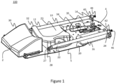
- FIG. 1 is drawing of an exemplary prone breast treatment table extension 100.
- the table extension includes a base 5 having a proximal end 2 and a distal end 4, a longitudinally adjustable hip/thigh support pad 30, a chest support 32 having an opening 23 for imaging or treatment of the patient's left breast.
- the table extension also includes an adjustable head support 34 and upper arm supports 35, 36.
- the table extension also includes two hand rails 10, 20.
- Each handrail 10, 20 has a proximal end 12, 22 and a distal end 14, 24.
- the handrails 10, 12 are shown in the locked position for patient use. In this position, distal ends 14, 24 of the handrails 10, 12 are shown locked into receiving supports 40, 42, respectively.
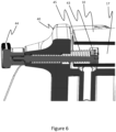
- the supports 40, 42 include spring-loaded retractable locking pins 43 (one of which is shown in Fig. 2 , in relation to receiving support 42), which may be retracted with knobs 44, 46, respectively, to remove the handrail distal ends 14, 24 from the locking supports 40, 42, respectively. Details of the locking pins are shown in cross section view FIG. 6 .
- Other means of retaining the distal ends of the handrails include, for example, spring-loaded clips, flexible straps, and spring-loaded collars that fit over the ends of the handrail.
- Handrail 20 is supported at its proximal end 22 by a hinge 27.
- the hinge 27 is mounted on a rotatable pedestal 28, which is attached to the patient table base 5.
- the attachment may be configured to allow quick removal and replacement of the handrail and hinge.
- a corresponding version (not shown) of the exemplary treatment table for examination or treatment of the patient's right breast is arranged as shown in FIG. 1 except that opening 23 is on the right-hand side of the table with respect to the prone patient.
- a similar hinge and rotatable pedestal attach the proximal end 12 of the left hand-rail 10 to the base 5 of the patient table extension.
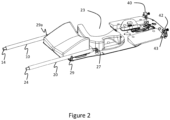
- FIG. 2 is a drawing of the exemplary patient table extension 100 of FIG. 1 with the handrails 10, 20 disengaged from the receiving supports 40, 42, respectively.
- the handrails may be rotated about the hinges (hinge 27 shown for handrail 20) to a position away from the patient's upper body such that the examination/treatment cavity 23 is fully accessible by medical equipment (not shown).
- a receiving cradle 29 accepts the right handrail 20, when in the unlatched position.
- a corresponding receiving cradle 29a accepts the left handrail 10.
- handrails 10, 20 may be rotated laterally and/or vertically about pedestals 28, which act as a pivot, in addition to vertically about hinge 27. This allows handrails 10, 20 to be repositioned without unnecessarily contacting a prone patient. The lateral rotation may also be useful to avoid any overhead equipment.
- the hinges may be replaced with springs.
- very stiff springs, matched to the patient's weight may be used to support the attached end of the handrails and may be used by the patient to lower herself onto the extension table.
- the handrail attachment mechanisms, whether rotatable pedestal or spring, at the proximal end may be releasably attached to the base 5 to allow the handrails 10, 20 to be fully removable.
- the attaching/releasing mechanism may be a cotter pin, a clip, spring-loaded pins fitting into mating slots or holes and the like.
- FIG. 3 shows the table extension 100 mounted on a treatment table base 200.
- the patient kneels on the treatment table base 200 on which the table extension 100 is mounted with her hands grabbing the handrails 10, 20 and "walks" her way slowly from the proximal end 2 of the table extension towards the distal end 4.
- Bars 10, 20 provide a reassuring and intuitive place to put the hands
- the left handrail 10 (right if using a device arranged for examination and/or treatment of the right breast) provides for sure and easy crossing of the large breast opening 23, and the handrails provide stability in all directions.
- the extension table may have only one moveable handrail on the side of the table extension having the opening and a fixed handrail on the other side. Having two handrails provides an advantage if the patient should start to fall to one side where she/he would be pulling up on one side and down the other to try and get back to a balanced position.
- FIG. 4 shows a partial view of a treatment table base 200 and a table extension 100.
- Four mounting rails 110 on the underside of the table extension 100 fit into corresponding slots 210 on the table base and secure the table extension 100 to the base 200.
- a latch (not shown) may be included on the table base to lock the mounting rails when fully inserted. Additionally, or alternatively, a latch (not shown) may be included on the table extension 100 to lock the extension to the base 200.
- FIG. 5 shows a patient treatment couch-top overlay 500, having handrails 510, 520 for use in computed tomography (CT) scanners.
- the overlay 500 in contrast to extension 100 described above in relation to Figs. 1-4 , is not an extension to a patient table as in FIGS 1-4 , but, rather, fits on top of a full body length treatment couch 505.
- the overlay 500 has an opening 523 for examination of the patient's left breast.
- Handrails 510 and 520 are releasable affixed to the overlay 500 in the same manner as described above for table extension 100.
- table extension 100 may be used in combination with an adaptor that has a top surface and bottom surfaces flush with that of the extension.
- FIG. 6 is a cross section view of an exemplary spring-loaded locking pin 43 as described above with respect to FIG. 1 .
- Locking pin 43 is part of an assembly that fits into cradle 40 for receiving the handrail 10. The pin 43 fits into a cavity 17 in the end of a handrail 10 when fully extended by the force of spring 45. Locking pin 43 can be retracted clear of the handrail cavity 17 by pulling on knob 44, thereby allowing the handrail 10 to be removed from the cradle 40.
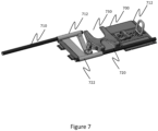
- FIG. 7 shows another embodiment of a treatment table extension 700.
- handrails 710, 720 are supported by tubes 712 and 722, respectively.
- the handrails 710, 720 can be slid away from the distal end 712 of the table extension 100 as shown with the top handrail 710, to allow for treatment or imaging equipment to access the open area 730.
- the handrails may be supported only by the tubes 712, 722 in a cantilevered fashion, as shown.
- the handrails 710, 720 may be supported at the distal end of the table 712 extension by a locking pin arrangement as shown, for example in FIG. 6 .
- the tube supports 712, 722 may also be used in a couch-top overlay such as is shown in FIG. 5 .
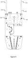
- FIGS. 8 and 9 show another embodiment of a treatment table extension 800.
- the handrails 820 and 822 are shorter than in FIGS. 1 and 2 .
- the hand rails 820, 822 extend from the same pivot positions 830, 832 relative to the table extension base 805 as do the handrails 10, 20 shown in FIGS. 1 and 2 .
- the distal ends 840, 842, of the hand handrails of FIGS 8 and 9 do not extend all the way to the distal end 804 of the treatment table extension as do the handrails 20, 22 in FIGS. 1 and 2 .
Landscapes
- Health & Medical Sciences (AREA)
- Life Sciences & Earth Sciences (AREA)
- Engineering & Computer Science (AREA)
- Medical Informatics (AREA)
- Biomedical Technology (AREA)
- Veterinary Medicine (AREA)
- Radiology & Medical Imaging (AREA)
- Animal Behavior & Ethology (AREA)
- General Health & Medical Sciences (AREA)
- Public Health (AREA)
- Nuclear Medicine, Radiotherapy & Molecular Imaging (AREA)
- Pathology (AREA)
- Biophysics (AREA)
- High Energy & Nuclear Physics (AREA)
- Physics & Mathematics (AREA)
- Optics & Photonics (AREA)
- Heart & Thoracic Surgery (AREA)
- Molecular Biology (AREA)
- Surgery (AREA)
- Apparatus For Radiation Diagnosis (AREA)
Claims (15)
- Patientenbehandlungstischverlängerung (100) zur Bildgebung und Behandlung der Brust eines Patienten in Bauchlage, Folgendes umfassend:eine ebene Basis (5) mit einer rechten und einer linken Seite, einem proximalen (2) und einem distalen (4) Ende und einer sich zwischen dem proximalen und distalen Ende befindlichen Öffnung (23) für entweder eine rechte oder linke Brust auf einer jeweiligen linken oder rechten Seite der Basis;eine Brustkorbstütze (32), die sich benachbart zu der Öffnung befindet; undmindestens einen Handlauf (10, 20), der sich auf der Seite befindet, die die Öffnungsseite aufweist und sich von dem distalen Ende zu dem proximalen Ende erstreckt,dadurch gekennzeichnet, dass jeder der mindestens einen Handläufe durch ein Scharnier (27) an der ebenen Basis (5) an dem proximalen Ende montiert ist und durch eine lösbare Halterung an dem distalen Ende zurückgehalten wird, wobei das Scharnier so konfiguriert ist, dass der Handlauf an dem distalen Ende angehoben und in Richtung des proximalen Endes gedreht werden kann.
- Patientenbehandlungstischverlängerung nach Anspruch 1, wobei der mindestens eine Handlauf ein erster Handlauf ist, der sich auf der linken Seite der ebenen Basis befindet, und sich ein zweiter Handlauf auf der rechten Seite der ebenen Basis befindet, wobei jedes jeweilige Scharnier an einem Drehpunkt montiert ist, der so konfiguriert ist, dass der erste oder zweite Handlauf von der Seite der ebenen Basis weggedreht werden kann.
- Patientenbehandlungstischverlängerung nach einem der Ansprüche 1 oder 2, wobei die lösbare Halterung einen federbelasteten Stift umfasst, der so konfiguriert ist, dass er in eine Öffnung an dem distalen Ende des Handlaufs passt.
- Patientenbehandlungstischverlängerung nach einem der Ansprüche 1-3, ferner Folgendes umfassend:
Aufnahmeablagen an dem proximalen Ende auf der linken und rechten Seite der ebenen Basis, wobei die Aufnahmeablagen so konfiguriert sind, dass sie den ersten und den zweiten Handlauf halten, wenn sie von der lösbaren Halterung weggedreht werden. - Patientenbehandlungstischverlängerung nach Anspruch 2, wobei der Drehpunkt lösbar an der ebenen Basis befestigt ist, um ein schnelles Entfernen und Ersetzen des Handlaufs zu ermöglichen.
- Patientenbehandlungstisch, Folgendes umfassend:eine Behandlungstischbasis undeine Behandlungstischverlängerung,wobei die Behandlungstischverlängerung abnehmbar an der Behandlungstischbasis befestigt ist, wobei die Behandlungstischverlängerung eine ebene Basis mit einer rechten und einer linken Seite, einem proximalen und einem distalen Ende und einer sich zwischen dem proximalen und distalen Ende befindlichen Öffnung für entweder eine rechte oder linke Brust auf einer jeweiligen linken oder rechten Seite der Basis aufweist;eine Brustkorbstütze, die sich benachbart zu der Öffnung befindet; undmindestens einen Handlauf, der sich auf der Seite befindet, die die Öffnungsseite aufweist und sich von dem distalen Ende zu dem proximalen Ende erstreckt,dadurch gekennzeichnet, dass jeder der mindestens einen Handläufe durch ein Scharnier an der ebenen Basis an dem proximalen Ende montiert ist und durch eine lösbare Halterung an dem distalen Ende zurückgehalten wird, wobei das Scharnier so konfiguriert ist, dass der Handlauf an dem distalen Ende angehoben und in Richtung des proximalen Endes gedreht werden kann.
- Patientenbehandlungstisch nach Anspruch 6, wobei der mindestens eine Handlauf ein erster Handlauf ist, der sich auf der linken Seite der ebenen Basis befindet, und sich ein zweiter Handlauf auf der rechten Seite der ebenen Basis befindet, wobei jedes jeweilige Scharnier an einem Drehpunkt montiert ist, der so konfiguriert ist, dass der erste oder zweite Handlauf von der Seite der ebenen Basis weggedreht werden kann.
- Patientenbehandlungstisch nach Anspruch 6 oder 7, wobei die lösbare Halterung einen federbelasteten Stift umfasst, der so konfiguriert ist, dass er in eine Öffnung an dem distalen Ende des Handlaufs passt.
- Patientenbehandlungstisch nach einem der Ansprüche 6-8, ferner Folgendes umfassend:
Aufnahmeablagen an dem proximalen Ende auf der linken und rechten Seite der ebenen Basis, wobei die Aufnahmeablagen so konfiguriert sind, dass sie den ersten und den zweiten Handlauf halten, wenn sie von der lösbaren Halterung weggedreht werden. - Patientenbehandlungstisch nach Anspruch 7, wobei der Drehpunkt lösbar an der ebenen Basis befestigt ist, um ein Entfernen und Ersetzen des Handlaufs zu ermöglichen.
- Patientenbehandlungstischauflage zur Bildgebung und Behandlung des Brust- oder Brustkorbbereichs eines Patienten in Bauchlage, Folgendes umfassend:eine ebene Basis mit einer rechten und einer linken Seite, einem proximalen und einem distalen Ende und einer sich zwischen dem proximalen und distalen Ende befindlichen Öffnung für entweder eine rechte oder linke Brust auf einer jeweiligen linken oder rechten Seite der Basis;eine Brustkorbstütze, die sich benachbart zu der Öffnung befindet; undmindestens einen Handlauf, der sich auf der Seite befindet, die die Öffnungsseite aufweist und sich von dem distalen Ende zu dem proximalen Ende erstreckt,dadurch gekennzeichnet, dass jeder der mindestens einen Handläufe durch ein Scharnier an der ebenen Basis an dem proximalen Ende montiert ist und durch eine lösbare Halterung an dem distalen Ende zurückgehalten wird, wobei das Scharnier so konfiguriert ist, dass der Handlauf an dem distalen Ende angehoben und in Richtung des proximalen Endes gedreht werden kann.
- Patientenbehandlungstischauflage nach Anspruch 11, wobei der mindestens eine Handlauf ein erster Handlauf ist, der sich auf der linken Seite der ebenen Basis befindet, und sich ein zweiter Handlauf auf der rechten Seite der ebenen Basis befindet, wobei jedes jeweilige Scharnier an einem Drehpunkt montiert ist, der so konfiguriert ist, dass der Handlauf von der Seite der ebenen Basis weggedreht werden kann.
- Patientenbehandlungstischauflage nach Anspruch 11 oder 12, wobei die lösbare Halterung einen federbelasteten Stift umfasst, der so konfiguriert ist, dass er in eine Öffnung an dem distalen Ende des Handlaufs passt.
- Patientenbehandlungstischauflage nach einem der Ansprüche 11-13, ferner Folgendes umfassend:
Aufnahmeablagen an dem proximalen Ende auf der linken und rechten Seite der ebenen Basis, wobei die Aufnahmeablagen so konfiguriert sind, dass sie den ersten und den zweiten Handlauf halten, wenn sie von der lösbaren Halterung weggedreht werden. - Patientenbehandlungstischauflage nach Anspruch 12, wobei der Drehpunkt lösbar an der ebenen Basis befestigt ist, um ein Entfernen und Ersetzen des Handlaufs zu ermöglichen.
Applications Claiming Priority (2)
| Application Number | Priority Date | Filing Date | Title |
|---|---|---|---|
| US201962949090P | 2019-12-17 | 2019-12-17 | |
| PCT/US2020/065563 WO2021127151A1 (en) | 2019-12-17 | 2020-12-17 | Patient imaging and treatment table extension with integrated handrails |
Publications (3)
| Publication Number | Publication Date |
|---|---|
| EP4076200A1 EP4076200A1 (de) | 2022-10-26 |
| EP4076200C0 EP4076200C0 (de) | 2025-05-21 |
| EP4076200B1 true EP4076200B1 (de) | 2025-05-21 |
Family
ID=74195105
Family Applications (1)
| Application Number | Title | Priority Date | Filing Date |
|---|---|---|---|
| EP20845255.7A Active EP4076200B1 (de) | 2019-12-17 | 2020-12-17 | Patientenbildgebungs- und behandlungstischverlängerung mit integrierten handläufen |
Country Status (3)
| Country | Link |
|---|---|
| US (1) | US12201462B2 (de) |
| EP (1) | EP4076200B1 (de) |
| WO (1) | WO2021127151A1 (de) |
Families Citing this family (2)
| Publication number | Priority date | Publication date | Assignee | Title |
|---|---|---|---|---|
| IT202300003399A1 (it) | 2023-02-27 | 2024-08-27 | Assing S P A | Tavolo telecomandato per il trattamento di esami radiologici |
| WO2026027917A1 (en) | 2024-07-29 | 2026-02-05 | Assing S.P.A. | Remote-controlled table for the treatment of radiological examinations |
Family Cites Families (19)
| Publication number | Priority date | Publication date | Assignee | Title |
|---|---|---|---|---|
| US5386447A (en) | 1992-09-23 | 1995-01-31 | Fischer Imaging Corporation | Mammographic screening and biopsy apparatus |
| US5778467A (en) | 1995-09-13 | 1998-07-14 | Standex International | Patient treatment apparatus |
| JP3601192B2 (ja) | 1996-06-28 | 2004-12-15 | 株式会社島津製作所 | 上肢固定具 |
| US5820552A (en) | 1996-07-12 | 1998-10-13 | United States Surgical Corporation | Sonography and biopsy apparatus |
| WO2004041089A2 (en) | 2002-11-08 | 2004-05-21 | Art Advanced Research Technologies Inc. | Method and apparatus for positioning a patient for a medical procedure on a breast |
| US6922859B2 (en) | 2002-11-29 | 2005-08-02 | Art Advanced Research Technologies Inc. | Table for positioning a patient for a medical procedure on a breast |
| US8406846B2 (en) | 2006-03-31 | 2013-03-26 | Shimadzu Corporation | Mammographic apparatus |
| WO2008062531A1 (en) | 2006-11-24 | 2008-05-29 | Shimadzu Corporation | Radiographic x-ray equipment |
| US9538991B2 (en) * | 2011-09-19 | 2017-01-10 | Koninklijke Philips N.V. | Integrated MR imaging and interventional coil device, method and system |
| US8914925B2 (en) * | 2012-02-08 | 2014-12-23 | Wayne County Employees' Retirement System | Mobile diagnostic assembly |
| CN104363958B (zh) | 2012-03-19 | 2017-08-08 | 列日大学 | 用于俯卧固定的患者支承装置 |
| US20140121499A1 (en) | 2012-10-26 | 2014-05-01 | Qfix Systems, Llc | Patient positioning device for prone breast simulation and radiation therapy |
| US9149205B2 (en) * | 2013-03-28 | 2015-10-06 | General Electric Company | Breast coil for use in magnetic resonance imaging |
| US9770175B2 (en) | 2014-03-13 | 2017-09-26 | First Sense Medical, Llc | Apparatus and method for detecting a presence of cancer |
| US10548542B2 (en) * | 2014-03-24 | 2020-02-04 | Universiteit Gent | Radiotherapy board and couch |
| ITBO20140080U1 (it) | 2014-09-30 | 2016-03-30 | Ims Giotto S P A | Dispositivo di supporto di un paziente per consentire l'esecuzione di un esame al seno. |
| JP2017012448A (ja) | 2015-06-30 | 2017-01-19 | キヤノン株式会社 | 乳房撮影装置 |
| WO2017142747A1 (en) | 2016-02-16 | 2017-08-24 | Zhang Jiaju | Prone breast board for high-dose-rate partial breast irradiation brachytherapy |
| WO2018006295A1 (zh) | 2016-07-06 | 2018-01-11 | 王楚 | 一种治疗床翻转机构 |
-
2020
- 2020-12-17 WO PCT/US2020/065563 patent/WO2021127151A1/en not_active Ceased
- 2020-12-17 US US17/784,777 patent/US12201462B2/en active Active
- 2020-12-17 EP EP20845255.7A patent/EP4076200B1/de active Active
Also Published As
| Publication number | Publication date |
|---|---|
| WO2021127151A1 (en) | 2021-06-24 |
| EP4076200A1 (de) | 2022-10-26 |
| US20220409151A1 (en) | 2022-12-29 |
| EP4076200C0 (de) | 2025-05-21 |
| US12201462B2 (en) | 2025-01-21 |
Similar Documents
| Publication | Publication Date | Title |
|---|---|---|
| US11684532B2 (en) | Method and apparatus for supporting and stabilizing a patient during hip distraction | |
| JP6317509B2 (ja) | 伸縮自在の開創器ホルダ | |
| EP4076200B1 (de) | Patientenbildgebungs- und behandlungstischverlängerung mit integrierten handläufen | |
| EP2722029B1 (de) | Kopfstützenvorrichtung für Wirbelsäulenoperationen | |
| US6629944B2 (en) | Limb-positioning and traction device | |
| US9433551B2 (en) | Protection device for surgery tables | |
| CN104080425B (zh) | 用于手术台的骶垫 | |
| US9572741B2 (en) | Surgical table arm support assembly and surgical table | |
| EP2932952B1 (de) | Chirurgisches unterstützungssystem | |
| US6471167B1 (en) | Surgical tray support system | |
| KR20140091670A (ko) | 수술대 및 부대용품 | |
| US7185656B2 (en) | System for restraining head and neck movement | |
| US20060253985A1 (en) | Head support apparatus for spinal surgery | |
| WO2009102757A2 (en) | Medical examination table and system for mounting accessories to the table | |
| US20160287461A1 (en) | Surgical table with combination footboard and patient transfer board | |
| US8365739B1 (en) | Device for positioning the sitting patient for epidural or spinal injection procedures | |
| BR112014005387B1 (pt) | kit e dispositivo para aplicação de tensão ao ombro de um paciente | |
| US6934980B2 (en) | Patient transfer system | |
| US20110120352A1 (en) | Table | |
| US20120180797A1 (en) | Modular pediatric platform | |
| US20250275877A1 (en) | Neonatal support system | |
| CN223715971U (zh) | 手术床护栏 | |
| RU2499577C2 (ru) | Ортопедическое устройство | |
| CN214968459U (zh) | 一种医用手托 | |
| WO2010099358A1 (en) | Table for application of a spica cast |
Legal Events
| Date | Code | Title | Description |
|---|---|---|---|
| STAA | Information on the status of an ep patent application or granted ep patent |
Free format text: STATUS: UNKNOWN |
|
| STAA | Information on the status of an ep patent application or granted ep patent |
Free format text: STATUS: THE INTERNATIONAL PUBLICATION HAS BEEN MADE |
|
| PUAI | Public reference made under article 153(3) epc to a published international application that has entered the european phase |
Free format text: ORIGINAL CODE: 0009012 |
|
| STAA | Information on the status of an ep patent application or granted ep patent |
Free format text: STATUS: REQUEST FOR EXAMINATION WAS MADE |
|
| 17P | Request for examination filed |
Effective date: 20220614 |
|
| AK | Designated contracting states |
Kind code of ref document: A1 Designated state(s): AL AT BE BG CH CY CZ DE DK EE ES FI FR GB GR HR HU IE IS IT LI LT LU LV MC MK MT NL NO PL PT RO RS SE SI SK SM TR |
|
| DAV | Request for validation of the european patent (deleted) | ||
| DAX | Request for extension of the european patent (deleted) | ||
| GRAP | Despatch of communication of intention to grant a patent |
Free format text: ORIGINAL CODE: EPIDOSNIGR1 |
|
| STAA | Information on the status of an ep patent application or granted ep patent |
Free format text: STATUS: GRANT OF PATENT IS INTENDED |
|
| INTG | Intention to grant announced |
Effective date: 20241211 |
|
| GRAS | Grant fee paid |
Free format text: ORIGINAL CODE: EPIDOSNIGR3 |
|
| GRAA | (expected) grant |
Free format text: ORIGINAL CODE: 0009210 |
|
| STAA | Information on the status of an ep patent application or granted ep patent |
Free format text: STATUS: THE PATENT HAS BEEN GRANTED |
|
| AK | Designated contracting states |
Kind code of ref document: B1 Designated state(s): AL AT BE BG CH CY CZ DE DK EE ES FI FR GB GR HR HU IE IS IT LI LT LU LV MC MK MT NL NO PL PT RO RS SE SI SK SM TR |
|
| REG | Reference to a national code |
Ref country code: GB Ref legal event code: FG4D |
|
| REG | Reference to a national code |
Ref country code: CH Ref legal event code: EP |
|
| REG | Reference to a national code |
Ref country code: DE Ref legal event code: R096 Ref document number: 602020051770 Country of ref document: DE |
|
| REG | Reference to a national code |
Ref country code: IE Ref legal event code: FG4D |
|
| U01 | Request for unitary effect filed |
Effective date: 20250613 |
|
| U07 | Unitary effect registered |
Designated state(s): AT BE BG DE DK EE FI FR IT LT LU LV MT NL PT RO SE SI Effective date: 20250625 |
|
| PG25 | Lapsed in a contracting state [announced via postgrant information from national office to epo] |
Ref country code: ES Free format text: LAPSE BECAUSE OF FAILURE TO SUBMIT A TRANSLATION OF THE DESCRIPTION OR TO PAY THE FEE WITHIN THE PRESCRIBED TIME-LIMIT Effective date: 20250521 |
|
| PG25 | Lapsed in a contracting state [announced via postgrant information from national office to epo] |
Ref country code: GR Free format text: LAPSE BECAUSE OF FAILURE TO SUBMIT A TRANSLATION OF THE DESCRIPTION OR TO PAY THE FEE WITHIN THE PRESCRIBED TIME-LIMIT Effective date: 20250822 Ref country code: NO Free format text: LAPSE BECAUSE OF FAILURE TO SUBMIT A TRANSLATION OF THE DESCRIPTION OR TO PAY THE FEE WITHIN THE PRESCRIBED TIME-LIMIT Effective date: 20250821 |
|
| PG25 | Lapsed in a contracting state [announced via postgrant information from national office to epo] |
Ref country code: PL Free format text: LAPSE BECAUSE OF FAILURE TO SUBMIT A TRANSLATION OF THE DESCRIPTION OR TO PAY THE FEE WITHIN THE PRESCRIBED TIME-LIMIT Effective date: 20250521 |
|
| PG25 | Lapsed in a contracting state [announced via postgrant information from national office to epo] |
Ref country code: HR Free format text: LAPSE BECAUSE OF FAILURE TO SUBMIT A TRANSLATION OF THE DESCRIPTION OR TO PAY THE FEE WITHIN THE PRESCRIBED TIME-LIMIT Effective date: 20250521 |
|
| PG25 | Lapsed in a contracting state [announced via postgrant information from national office to epo] |
Ref country code: RS Free format text: LAPSE BECAUSE OF FAILURE TO SUBMIT A TRANSLATION OF THE DESCRIPTION OR TO PAY THE FEE WITHIN THE PRESCRIBED TIME-LIMIT Effective date: 20250821 |
|
| PG25 | Lapsed in a contracting state [announced via postgrant information from national office to epo] |
Ref country code: IS Free format text: LAPSE BECAUSE OF FAILURE TO SUBMIT A TRANSLATION OF THE DESCRIPTION OR TO PAY THE FEE WITHIN THE PRESCRIBED TIME-LIMIT Effective date: 20250921 |
|
| PG25 | Lapsed in a contracting state [announced via postgrant information from national office to epo] |
Ref country code: SM Free format text: LAPSE BECAUSE OF FAILURE TO SUBMIT A TRANSLATION OF THE DESCRIPTION OR TO PAY THE FEE WITHIN THE PRESCRIBED TIME-LIMIT Effective date: 20250521 |
|
| PG25 | Lapsed in a contracting state [announced via postgrant information from national office to epo] |
Ref country code: CZ Free format text: LAPSE BECAUSE OF FAILURE TO SUBMIT A TRANSLATION OF THE DESCRIPTION OR TO PAY THE FEE WITHIN THE PRESCRIBED TIME-LIMIT Effective date: 20250521 |
|
| U20 | Renewal fee for the european patent with unitary effect paid |
Year of fee payment: 6 Effective date: 20251217 |
|
| PG25 | Lapsed in a contracting state [announced via postgrant information from national office to epo] |
Ref country code: SK Free format text: LAPSE BECAUSE OF FAILURE TO SUBMIT A TRANSLATION OF THE DESCRIPTION OR TO PAY THE FEE WITHIN THE PRESCRIBED TIME-LIMIT Effective date: 20250521 |
|
| PLBE | No opposition filed within time limit |
Free format text: ORIGINAL CODE: 0009261 |
|
| STAA | Information on the status of an ep patent application or granted ep patent |
Free format text: STATUS: NO OPPOSITION FILED WITHIN TIME LIMIT |