EP2931395B1 - Distributor in mass transfer column and method of use - Google Patents
Distributor in mass transfer column and method of use Download PDFInfo
- Publication number
- EP2931395B1 EP2931395B1 EP13863615.4A EP13863615A EP2931395B1 EP 2931395 B1 EP2931395 B1 EP 2931395B1 EP 13863615 A EP13863615 A EP 13863615A EP 2931395 B1 EP2931395 B1 EP 2931395B1
- Authority
- EP
- European Patent Office
- Prior art keywords
- troughs
- liquid
- primary
- trough
- side walls
- Prior art date
- Legal status (The legal status is an assumption and is not a legal conclusion. Google has not performed a legal analysis and makes no representation as to the accuracy of the status listed.)
- Active
Links
Images


Classifications
-
- F—MECHANICAL ENGINEERING; LIGHTING; HEATING; WEAPONS; BLASTING
- F28—HEAT EXCHANGE IN GENERAL
- F28F—DETAILS OF HEAT-EXCHANGE AND HEAT-TRANSFER APPARATUS, OF GENERAL APPLICATION
- F28F25/00—Component parts of trickle coolers
- F28F25/02—Component parts of trickle coolers for distributing, circulating, and accumulating liquid
- F28F25/04—Distributing or accumulator troughs
-
- B—PERFORMING OPERATIONS; TRANSPORTING
- B01—PHYSICAL OR CHEMICAL PROCESSES OR APPARATUS IN GENERAL
- B01D—SEPARATION
- B01D3/00—Distillation or related exchange processes in which liquids are contacted with gaseous media, e.g. stripping
- B01D3/008—Liquid distribution
-
- B—PERFORMING OPERATIONS; TRANSPORTING
- B01—PHYSICAL OR CHEMICAL PROCESSES OR APPARATUS IN GENERAL
- B01D—SEPARATION
- B01D3/00—Distillation or related exchange processes in which liquids are contacted with gaseous media, e.g. stripping
- B01D3/14—Fractional distillation or use of a fractionation or rectification column
- B01D3/16—Fractionating columns in which vapour bubbles through liquid
- B01D3/18—Fractionating columns in which vapour bubbles through liquid with horizontal bubble plates
- B01D3/20—Bubble caps; Risers for vapour; Discharge pipes for liquid
-
- B—PERFORMING OPERATIONS; TRANSPORTING
- B01—PHYSICAL OR CHEMICAL PROCESSES OR APPARATUS IN GENERAL
- B01F—MIXING, e.g. DISSOLVING, EMULSIFYING OR DISPERSING
- B01F23/00—Mixing according to the phases to be mixed, e.g. dispersing or emulsifying
- B01F23/20—Mixing gases with liquids
- B01F23/21—Mixing gases with liquids by introducing liquids into gaseous media
-
- B—PERFORMING OPERATIONS; TRANSPORTING
- B01—PHYSICAL OR CHEMICAL PROCESSES OR APPARATUS IN GENERAL
- B01D—SEPARATION
- B01D3/00—Distillation or related exchange processes in which liquids are contacted with gaseous media, e.g. stripping
- B01D3/14—Fractional distillation or use of a fractionation or rectification column
- B01D3/32—Other features of fractionating columns ; Constructional details of fractionating columns not provided for in groups B01D3/16 - B01D3/30
-
- B—PERFORMING OPERATIONS; TRANSPORTING
- B01—PHYSICAL OR CHEMICAL PROCESSES OR APPARATUS IN GENERAL
- B01D—SEPARATION
- B01D53/00—Separation of gases or vapours; Recovering vapours of volatile solvents from gases; Chemical or biological purification of waste gases, e.g. engine exhaust gases, smoke, fumes, flue gases, aerosols
- B01D53/14—Separation of gases or vapours; Recovering vapours of volatile solvents from gases; Chemical or biological purification of waste gases, e.g. engine exhaust gases, smoke, fumes, flue gases, aerosols by absorption
- B01D53/18—Absorbing units; Liquid distributors therefor
-
- Y—GENERAL TAGGING OF NEW TECHNOLOGICAL DEVELOPMENTS; GENERAL TAGGING OF CROSS-SECTIONAL TECHNOLOGIES SPANNING OVER SEVERAL SECTIONS OF THE IPC; TECHNICAL SUBJECTS COVERED BY FORMER USPC CROSS-REFERENCE ART COLLECTIONS [XRACs] AND DIGESTS
- Y10—TECHNICAL SUBJECTS COVERED BY FORMER USPC
- Y10T—TECHNICAL SUBJECTS COVERED BY FORMER US CLASSIFICATION
- Y10T137/00—Fluid handling
- Y10T137/0318—Processes
Definitions
- the present invention relates generally to columns in which mass transfer and heat exchange occur and, more particularly, to liquid distributors used in such columns and methods of liquid distribution using such liquid distributors.
- mass transfer column refers to a column in which mass transfer and/or heat exchanger occur.
- mass transfer columns include distillation, absorption, stripping, and extraction columns.
- one or more liquid and/or vapor streams are brought into contact with each other to effect mass transfer and/or heat exchange between the liquid and/or vapor streams.
- Beds of structured or random packing are normally used in such mass transfer columns to facilitate intimate contact between the liquid and/or vapor streams and thereby enhance the desired mass transfer and/or heat exchange between the streams.
- the liquid stream descends through the bed of packing and the vapor stream ascends through the packing bed.
- the denser phase descends through the bed and the less dense phase ascends through the bed.
- Uniform distribution of the descending liquid stream across the horizontal cross section of the bed of structured or random packing is important in order to maintain a uniform interaction between the liquid stream and the ascending vapor stream.
- Various types of liquid distributors are used in an attempt to provide a uniform distribution of the liquid stream as it enters the top of the bed of packing material.
- a feed box or parting box receives a liquid stream from an overlying collector or a feed line and distributes it to a number of elongated and parallel troughs that underlie or extend horizontally from the parting box. Spaced-apart holes are formed in the side walls of the troughs to allow liquid to exit the troughs in individual liquid streams.
- Splash baffles are spaced outwardly from and parallel to the side walls of the troughs so that the individual liquid streams exiting the troughs through the holes are directed onto the splash baffles. The individual liquid streams then descend along and spread across the splash baffles before dripping off the lower edge of the baffles into the bed of packing material. Examples of liquid distributors of this type are shown in U.S. Patent Nos. 6,722,639 and 7,125,004 . Documents DE 3409524 , DE 3013783 , US 2008/245416 describe liquid distributors.
- the number and size of the holes in the side walls of the trough is selected based on the anticipated volumetric flow rate of the liquid stream into the troughs.
- the total open area presented by the holes must be designed to permit a sufficient liquid head to develop within the troughs and thereby generate the necessary force to cause the individual liquid streams to exit the holes with enough momentum to reach the outwardly-spaced splash baffles.
- the designed liquid volumetric flow rate is low, the total flow capacity of the holes must be reduced to allow a sufficient liquid head to develop in the troughs. This reduction in flow capacity can be achieved by reducing the size of the holes and/or by increasing the spacing between adjacent holes to reduce the total number of holes. Both of these options create potential disadvantages.
- the present invention is directed to a liquid distributor for receiving and distributing a liquid stream, as described in claim 1.
- the invention is directed to a method of distributing liquid to a layer of mass transfer devices using a liquid distributor as described above.
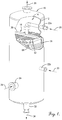
- a mass transfer column is represented broadly by the numeral 10 and includes an upright cylindrical shell 12 that defines an open interior region 14.
- a liquid distributor 16 of the present invention is positioned in the open interior region 14 and is used to distribute a descending liquid stream uniformly across the upper end of one or more layers 18 of mass transfer devices such as structured, grid or random packing material. The liquid stream then descends through the layer(s) 18 of mass transfer devices for mass and/or heat transfer with a vapor stream ascending through the layer(s) 18 of mass transfer devices.
- the mass transfer column 10 is of a type used to process liquid and vapor streams to obtain fractionation or other products.
- the shell 12 of the column 10 is shown in a cylindrical configuration, other shapes may be used.
- the shell 12 is of any suitable diameter and height and is constructed from rigid materials that are preferably inert to or are otherwise compatible with the fluids, temperatures, and pressures present within the column 10.
- Liquid streams 20 are directed to the column 10 through feed lines 22a and 22b positioned at appropriate locations along the height of the column 10.
- Feed line 22a normally carries only liquid and feed line 22b may carry liquid, vapor and a mixture of liquid and vapor.
- additional liquid feed lines may be utilized if desired.
- only one vapor feed line 24 carrying a vapor stream 26 is illustrated, but additional vapor feed lines can be included if necessary or desired for the vapor and liquid processing occurring within the column 10. It will also be appreciated that the vapor stream 26 can be generated within the column 10 rather than being introduced into the column 10 through the feed line 24.
- the column 10 further includes an overhead line 28 for removing a vapor product or byproduct 30 from the column 10.
- a bottom stream takeoff line 32 is provided for removing a liquid product or byproduct 34 from the column 10.
- Other column components such as reflux stream lines, reboilers, condensers, vapor horns, and the like may be present, but are not illustrated because they are convenient in nature and are not believed to be necessary for an understanding of the present invention.
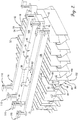
- one embodiment of the liquid distributor 16 of the present invention includes an elongated central parting box 36 that receives a descending liquid stream, such as the liquid stream 20 that has been delivered by the feed line 22a to the open internal region 14 within the shell 12 of the column 10.
- the parting box 36 need not receive the liquid stream 20 directly from the feed line 22a. Instead, the liquid stream 20 may first be subjected to one or more processing steps and then collected by a conventional liquid collector (not shown) for subsequent delivery to the parting box 36.
- the parting box 36 extends in a first direction along a central horizontal axis or diameter of the shell 12 of the column 10.
- the parting box 36 has a longitudinal length that is approximately the same as the diameter of the shell 12 or a substantial portion of the diameter.
- more than one parting box 36 may be used, in which event the parting boxes 36 extend in parallel and co-planar relationship along imaginary chords of the shell 12.
- the parting box 36 has a rectilinear cross section with parallel and spaced-apart side walls 38 and 40 that extend along the long dimension of the parting box 36 and parallel and spaced-apart side walls 42 and 44 that extend along the short dimension or ends of the parting box 36.
- a floor 46 is joined to the lower edges and an optional cover 48 is joined to the upper edges of the side walls 40, 42, 44, and 46.
- the optional cover 48 includes an opening 50 through which the liquid stream 20 is delivered to the interior of the parting box 36.
- the parting box 36 feeds liquid to a plurality of elongated primary troughs 52 that extend in spaced-apart, generally parallel and co-planar relationship to each other.
- the primary troughs 52 extend along their longitudinal length at an angle, such as an angle of 90°, to the longitudinal length of the parting box 36.
- the primary troughs 52 each have a longitudinal length sufficient to extend across all or a substantial portion of the cross section of the shell 12 at their locational placement.
- the number of and lateral spacing between adjacent primary troughs 52 is selected to provide the desired liquid drip-point density in the underlying layer 18 of mass transfer devices.
- each primary trough 52 is of generally rectilinear cross section and is constructed with parallel and spaced-apart side walls 54 and 56 that extend along the long dimension of the primary trough 52, parallel and spaced-apart side walls 58 and 60 that extend along the short dimension or ends of the primary troughs 52, and a floor 62 that is joined to the lower edges of the side walls 54, 56, 58, and 60.
- the parting box 36 is positioned on top of the primary troughs 52 and the liquid in the parting box 36 is delivered to the interior of the primary troughs 52 through openings 63 positioned in the floor 46 of the parting box 36. Openings (not shown) may be provided in the side walls 38 and 40 of the parting box 36 to provide an additional or alternative route for liquid to exit the parting box 36 and flow downwardly into the primary troughs 52.
- the parting box 36 and the primary troughs 52 may be positioned in generally co-planar relationship with the primary troughs 52 extending outwardly from the side walls 38 and 40 of the parting box 36.
- openings are provided in the side walls 38 and 40 of the parting box 36 to allow liquid to flow from the parting box 36 to the primary troughs 52.
- a plurality of liquid discharge holes 64 are provided at the same elevation above the floor 62 in one or both of the longer side walls 54 and 56 of each primary trough 52.
- the liquid discharge holes 64 can be of any desired shape, such as circular, triangular or vertically elongated. The size, number and spacing of the liquid discharge holes 64 are selected to accommodate the designed volumetric flow rate of liquid into the primary troughs 52 so that liquid does not overflow the top of the primary troughs 52 during normal operational conditions.
- Overflow holes 66 or slots may be provided in the side walls 54 and 56 at a level above the liquid discharge holes 64 to allow for the controlled discharge of excess liquid that accumulates within the primary troughs 52 when the liquid flow rate into the primary troughs 52 exceeds the flow capacity of the liquid discharge holes 64.
- Each primary trough 52 is paired with a secondary trough 68 that is positioned to receive liquid exiting the primary trough 52 through the liquid discharge holes 64 in the side wall 54 or side wall 56.
- secondary troughs 68 are positioned along both of the side walls 54 and 56 or a single secondary trough 68 is positioned to receive liquid from the liquid discharge holes 64 in both of the side walls 54 and 56.
- Each secondary trough 68 is generally rectilinear in cross section and has a longitudinal length that is the same or approximately the same as that of the paired primary trough 52.
- the secondary troughs 68 each have spaced-apart and parallel side walls 70 and 72 that extend along the long dimension of the secondary troughs 68, spaced-apart and parallel side walls 74 and 76 that extend along the short dimension or ends of the secondary troughs, and a floor 78 that is joined to a lower edge of the side walls 70, 72, 74, and 76.
- the side wall 70 of the secondary trough 68 that faces and is adjacent the side wall 54 or 56 of the primary trough 52 having the liquid discharge holes 64 is in contact with and joined to the side wall 54 or 56 of the primary trough 52.
- the side wall 70 of the secondary trough 68 is closely spaced from the side wall 54 or 56 of the primary trough 52 by a distance that still permits liquid exiting from the liquid discharge holes 64 to enter the paired secondary trough 68.
- the side wall 70 of the secondary trough has inlet holes 80 aligned with the liquid discharge holes 64 in the side wall 54 or 56 of the primary trough 52.
- the top edge of the side wall 70 is positioned below the level of the liquid discharge holes 64 in the side wall 54 or 56 of the primary trough 52 so that liquid exiting the primary trough 52 through the liquid discharge holes 64 enters the secondary trough 68 through is its open top.
- the side wall 72 of each secondary trough 52 that is opposite from the side wall 70 that is adjacent to the primary trough 52 has a plurality of liquid discharge holes 82.
- the liquid discharge holes 82 can be of any desired shape, such as circular, triangular or vertically elongated. The size, number and spacing of the liquid discharge holes 82 are selected to accommodate the designed volumetric flow rate of liquid into the secondary troughs 68 so that liquid does not overflow the top of the secondary troughs 68 during normal operational conditions.
- the liquid discharge holes 82 are each positioned at the desired and normally the same elevation in the side wall 72.
- the liquid discharge holes 82 are located in a lower portion 84 of the side wall 72 that is bent away from a vertical plane at a preselected angle toward the opposite side wall 70 and the primary trough 52.
- the floor 78 slopes downwardly from the opposite side wall 70 toward the lower portion 84 of the side wall 72 so that the floor 78 directs liquid toward the liquid discharge holes 82.
- Overflow holes 86 or slots may be provided in the side wall 72 at a level above the liquid discharge holes 82 to allow for the controlled discharge of excess liquid that accumulates within the secondary troughs 68 when the liquid flow rate into the secondary troughs 68 exceeds the flow capacity of the liquid discharge holes 82.
- a plurality of spaced-apart dimples 88 extend downwardly on an undersurface of the floor 78 and the lower portion 84 of the side wall 72.
- the dimples 88 are placed between adjacent liquid discharge holes 82 to create drip points that interrupt the longitudinal flow of liquid along the undersurface of the floor 78 and the lower portion 84 of the side wall 72.
- the liquid discharge holes 82 can also be formed by punching to create a slight burr surrounding the liquid discharge holes 82 to reduce the opportunity for liquid to track along the outer surface of the side wall 72.
- a splash baffle 90 is positioned adjacent each secondary trough 52 at a location to receive the liquid that exits the secondary trough 52 through the liquid discharge holes 82.
- the splash baffle 90 extends longitudinally along all or substantially all of the longitudinal length of the secondary trough 52.
- the splash baffle 90 has a planar upper segment 92 that extends vertically along the side wall 72, a planar intermediate segment 94 that is angled to underlie the secondary trough, and a planar lower segment 96 that extends vertically downward below the associated primary trough 52 and has a serrated bottom edge.
- Spacer dimples 98 that extend outwardly from the side wall 72 of the secondary trough 68 are in contact with the upper segment 92 of the splash baffle 90 to create a slight spacing between the upper segment 92 and the side wall 72.
- the upper segment 92 of the splash baffle 90 extends a preselected distance below the secondary trough 68 so that the intermediate portion 94 of the splash baffle 90 is spaced a preselected distance below the liquid discharge holes 82. This spacing between the intermediate portion 94 and the liquid discharge holes 82 creates an outlet clearance for liquid to exit the liquid discharge holes 82. In embodiments where the lower portion 84 of the side wall 72 is not bent away from the vertical, additional spacing must be provided between the liquid discharge holes 82 and the upper portion of the splash baffle 90 to provide the necessary outlet clearance.
- a planar vertical baffle 100 extends downwardly from the side wall 56 of each primary trough 52 a sufficient distance so that its lower region is spaced horizontally from the lower segment 96 of the splash baffle 90 to form an elongated liquid discharge outlet 102 that underlies the longitudinal length of the primary trough 52.
- the baffle 100 is not used and the liquid discharge outlet 102 is formed by the lower segments 96 of the two splash baffles 90 that are mirror images of each other.
- the secondary troughs 68 may be in the same plane as the primary troughs 52 or the secondary trough 68 may be displaced somewhat from the plane of the primary troughs 52 so that at least a portion of the secondary troughs 68 extends below the primary troughs 52.
- the internal volume of the secondary trough 68 in one embodiment is less than that of the primary troughs 52.
- the total liquid flow capacity of the liquid discharge holes 64 in the side walls 54 and/or 56 of the primary troughs 52 may be the same, greater than, or less than that of the liquid discharge holes 82 in the side walls 72 of the secondary troughs 68.
- the number of liquid discharge holes 82 in the side walls 72 of the secondary troughs 68 is greater than the number of liquid discharge holes 64 in the side walls 54 and/or 56 of the primary troughs 52 so that the secondary troughs 68 act as flow multipliers to increase the lateral spreading of the liquid on the splash baffles 90.
- two beams 108 are equally spaced on opposite sides of the parting box 36 and are welded or otherwise secured to the top edges of the primary troughs 52.
- the beams 108 support and align the primary troughs 52.
- Support clips 110 are positioned at the ends of the beams 108 and the parting box 36 and may be secured to a support ring (not shown) or other structure that is attached to the shell 12 of the column 10.
- Other methods of supporting the liquid distributor 16 such as grid supports placed on the underlying layer 18 of mass transfer devices, can be used in place of or in addition to the support clips 110.
- the beams 108 and support clips 110 are not shown in Fig. 1 to simplify that illustration of the liquid distributor 16.
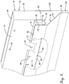
- liquid that has been delivered to one of the primary troughs 52 by the parting box 36 (not shown in Fig. 5 ), accumulates within the primary trough 52.
- the liquid is discharged into the secondary trough 68 through the liquid discharge holes 64 and through the inlet holes 80.
- the liquid is discharged as individual primary liquid streams designed by the arrow 104.
- the liquid from the individual primary liquid streams 104 accumulates within the secondary troughs 68 and is directed by the floor 78 to the liquid discharge openings 82 in the lower portion 84 of side wall 72.
- the liquid is then discharged from the secondary troughs 68 through the liquid discharge openings 82 as individual secondary liquid streams designed by the arrow 106. Any overflow from the secondary troughs 68 exits through the overflow holes or slots 86 and descends in the spacing between the side wall 72 and the upper segment 92 of the splash baffle 90.
- the individual secondary liquid streams 106 are directed against the splash baffle 90 and then descend and spread laterally along the surface of the splash baffle 90.
- the surface of the splash baffle 90 is treated with surface texturing to facilitate the lateral spread of the liquid.
- the surface texturing is provided on a thinner layer of material that is more easily worked and is then laminated onto the surface of the splash baffle 90.
- the use of the secondary troughs 68 allows larger liquid discharge holes 64 that are spaced further apart to be provided in the side walls 54 and/or 56 of the primary troughs 52 even in applications where the liquid distributor 16 is designed for low liquid flow conditions.
- the larger liquid discharge holes 64 are advantageous in that they are less prone to becoming plugged, such as by debris or scale.
- the secondary troughs 68 serve to cause greater lateral spreading of the liquid on the splash baffles 90 than would otherwise result from flowing the liquid directly from the primary baffles 52 onto the splash baffles 90.
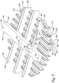
- Liquid distributor 216 has many of the same components as the liquid distributor 16 previously described and the same reference numerals with the prefix "2" are used to designate like components.
- Liquid distributor comprises a parting box 236 constructed in the same manner as the parting box 36 previously described and primary troughs 252 that are the same as primary troughs 52.
- the liquid distributor 216 further comprises secondary troughs 268 that are generally of the same constructions as secondary troughs 68 except they extend perpendicular to the primary troughs 252 and liquid does not feed into the secondary troughs 268 through inlet holes in a side wall 270 of the secondary troughs 268 as is the case with the secondary troughs 68 of the first embodiment.
- Liquid discharge holes 264 in the side walls 254 and 256 of the primary trough 252 allow the liquid to exit the primary troughs 252 as individual primary liquid streams and enter the associated secondary troughs 268.
- a cutout 269 is provided in the side walls 70 and 72 of each secondary trough 268 to receive the primary trough 252 so that liquid is additionally able to enter the secondary troughs 268 through holes (not shown) in a floor 262 of each primary trough 252.
- the liquid then exits the secondary troughs 268 and impacts and flows down splash baffles 290 in the same manner as previously described for delivery as a continuous curtain of liquid into an underlying layer (not shown) of mass transfer devices.
- Two splash baffles 290 are provided for each secondary trough 268 when liquid is discharged from both side walls 270 and 272.
- a single splash baffle 290 is used in combination with a planar baffle, such as the baffle 100 used in the liquid distributor 16 described above.
- the number of secondary troughs 268 can be selected independently of the number of primary troughs 252. In both embodiments of the liquid distributor 16 and 216, separate secondary troughs 68 and 268 may be associated with each of the liquid discharge holes 64 and 264 in the associated primary troughs 52 and 252.
Landscapes
- Chemical & Material Sciences (AREA)
- Chemical Kinetics & Catalysis (AREA)
- Engineering & Computer Science (AREA)
- Physics & Mathematics (AREA)
- Thermal Sciences (AREA)
- Mechanical Engineering (AREA)
- General Engineering & Computer Science (AREA)
- Vaporization, Distillation, Condensation, Sublimation, And Cold Traps (AREA)
- Feeding, Discharge, Calcimining, Fusing, And Gas-Generation Devices (AREA)
- Physical Or Chemical Processes And Apparatus (AREA)
- Gas Separation By Absorption (AREA)
- Extraction Or Liquid Replacement (AREA)
Applications Claiming Priority (3)
| Application Number | Priority Date | Filing Date | Title |
|---|---|---|---|
| US201261737517P | 2012-12-14 | 2012-12-14 | |
| US14/066,295 US9089787B2 (en) | 2012-12-14 | 2013-10-29 | Distributor in mass transfer column and method of use |
| PCT/US2013/067677 WO2014092875A1 (en) | 2012-12-14 | 2013-10-31 | Distributor in mass transfer column and method of use |
Publications (3)
| Publication Number | Publication Date |
|---|---|
| EP2931395A1 EP2931395A1 (en) | 2015-10-21 |
| EP2931395A4 EP2931395A4 (en) | 2016-07-27 |
| EP2931395B1 true EP2931395B1 (en) | 2017-09-27 |
Family
ID=50929543
Family Applications (1)
| Application Number | Title | Priority Date | Filing Date |
|---|---|---|---|
| EP13863615.4A Active EP2931395B1 (en) | 2012-12-14 | 2013-10-31 | Distributor in mass transfer column and method of use |
Country Status (11)
| Country | Link |
|---|---|
| US (2) | US9089787B2 (enExample) |
| EP (1) | EP2931395B1 (enExample) |
| JP (1) | JP6321030B2 (enExample) |
| KR (1) | KR102117267B1 (enExample) |
| BR (1) | BR112015013048B1 (enExample) |
| CA (1) | CA2889084C (enExample) |
| ES (1) | ES2650994T3 (enExample) |
| MX (1) | MX365854B (enExample) |
| RU (1) | RU2621766C2 (enExample) |
| TW (1) | TWI624296B (enExample) |
| WO (1) | WO2014092875A1 (enExample) |
Families Citing this family (15)
| Publication number | Priority date | Publication date | Assignee | Title |
|---|---|---|---|---|
| CA2689266A1 (en) * | 2009-12-23 | 2011-06-23 | Aker Solutions Canada Inc. | Improved distributor |
| US9089787B2 (en) * | 2012-12-14 | 2015-07-28 | Koch-Glitsch, Lp | Distributor in mass transfer column and method of use |
| FR3024948A1 (fr) * | 2014-08-20 | 2016-02-26 | Air Liquide | Dispositif de distribution comprenant un repartiteur a canaux polygonaux et ensemble de mise en contact comprenant un tel dispositif de distribution |
| CN105276852B (zh) * | 2015-11-24 | 2018-04-20 | 珠海格力电器股份有限公司 | 一种滴淋装置及溴化锂机组 |
| US10427113B2 (en) | 2017-07-18 | 2019-10-01 | Cnh Industrial Canada, Ltd. | Horizontal product distribution system using static baffles in a distributor |
| EP3437717A1 (en) * | 2017-08-01 | 2019-02-06 | Alfa Laval Corporate AB | A scrubber for cleaning of a gas |
| EP3447425A1 (de) * | 2017-08-22 | 2019-02-27 | Linde Aktiengesellschaft | Einbauten in einem gewickelten wärmeübertrager zur unterdrückung von gaswirbeln |
| DE202017105557U1 (de) * | 2017-09-14 | 2018-12-17 | HUGO PETERSEN GmbH | Berieselungssystem |
| FR3074055B1 (fr) | 2017-11-30 | 2022-06-03 | Ifp Energies Now | Plateau distributeur de gaz pour fond de colonne de contact gaz/liquide comprenant une zone de collecte de liquide partiellement recouverte par des cheminees de gaz |
| JP7015284B2 (ja) * | 2018-09-28 | 2022-02-02 | 株式会社デンソー | 水散布冷却装置 |
| FR3100320B1 (fr) * | 2019-09-02 | 2022-02-18 | Air Liquide | Dispositif de distribution destiné à une colonne de séparation gaz/liquide |
| EP3904280A1 (en) * | 2020-04-29 | 2021-11-03 | Yara International ASA | Absorption column comprising a feed box having a serrated weir and a structured packing and process for the production of nitric acid |
| EP3995195A1 (en) * | 2020-11-06 | 2022-05-11 | Sulzer Management AG | A multistage liquid distributor for a separation device comprising a dual-trough pre-distributor |
| WO2025219807A1 (en) * | 2024-04-18 | 2025-10-23 | Koch-Glitsch, Lp | Liquid distributor for use in a mass transfer column and method employing same |
| KR20250154010A (ko) * | 2024-04-19 | 2025-10-28 | 한화솔루션 주식회사 | 잔류 모노머 제거장치 |
Family Cites Families (26)
| Publication number | Priority date | Publication date | Assignee | Title |
|---|---|---|---|---|
| US3158171A (en) * | 1962-08-31 | 1964-11-24 | Us Stoneware Co | Distributor |
| US3360246A (en) * | 1966-02-25 | 1967-12-26 | Us Stoneware Inc | Distributor with bed-level limiter |
| US3491792A (en) * | 1968-02-02 | 1970-01-27 | Norton Co | Weir construction and liquids distributor embodying the same |
| JPS4933729B1 (enExample) * | 1968-09-27 | 1974-09-09 | ||
| US3937769A (en) * | 1973-12-27 | 1976-02-10 | Norton Company | Liquid distributor |
| JPS55159805A (en) * | 1979-06-01 | 1980-12-12 | Nagaoka Kinmo Kk | Attaching method of distributor |
| DE3013783A1 (de) * | 1979-11-08 | 1981-10-15 | Julius Montz Gmbh, 4010 Hilden | Fluessigkeitsverteiler fuer eine gegenstromkolonne |
| US4264538A (en) * | 1980-05-14 | 1981-04-28 | Norton Company | Liquid distributor |
| DE3409524C1 (de) | 1984-03-15 | 1985-09-05 | Julius Montz Gmbh, 4010 Hilden | Flüssigkeitsverteiler für eine Gegenstromkolonne |
| US4569364A (en) * | 1985-05-20 | 1986-02-11 | Fractionation Research, Inc. | Variable flow self-cleaning liquid distribution element and liquid distribution assembly employing a plurality of such elements |
| CH671165A5 (enExample) * | 1987-03-02 | 1989-08-15 | Sulzer Ag | |
| US4816191A (en) | 1988-01-19 | 1989-03-28 | Koch Engineering Company, Inc. | Distributor for liquid-gas contact column and method of preparation and use |
| US5051214A (en) * | 1989-01-13 | 1991-09-24 | Glitsch, Inc. | Double-deck distributor and method of liquid distribution |
| US5061407A (en) * | 1990-08-08 | 1991-10-29 | Nutter Dale E | Liquid distributor for gas-liquid contact apparatus |
| JPH086499Y2 (ja) * | 1990-09-25 | 1996-02-28 | 日鉄化工機株式会社 | 液分散器 |
| JPH08261690A (ja) * | 1994-04-05 | 1996-10-11 | Mitsubishi Corp | 物質及び/又は熱交換塔用の液体分配器 |
| US5906773A (en) | 1997-07-30 | 1999-05-25 | Norton Company | Liquid distributor |
| ATE291948T1 (de) * | 1998-11-30 | 2005-04-15 | Sulzer Chemtech Ag | Flüssigkeitsverteiler für packungskolonnen |
| ATE286771T1 (de) * | 1998-11-30 | 2005-01-15 | Sulzer Chemtech Ag | Gegenstromkolonne mit flüssigkeitsverteiler |
| US6722639B2 (en) * | 2001-04-10 | 2004-04-20 | Koch-Glitsch, Lp | Liquid distributor in mass transfer column and method of installation and use |
| EP1464370A1 (de) | 2003-03-17 | 2004-10-06 | Sulzer Chemtech AG | Feinverteiler für eine Flüssigkeit |
| US7125004B2 (en) * | 2003-12-15 | 2006-10-24 | Koch-Glitsch, Lp | Liquid distributor for use in mass transfer column |
| DE102005045745A1 (de) * | 2005-09-23 | 2007-04-12 | Degussa Ag | Vorrichtung und Verfahren zur Verteilung zweier nicht miteinander mischbarer Flüssigkeiten |
| EP1813347A1 (de) * | 2006-01-25 | 2007-08-01 | Sulzer Chemtech AG | Verteiler zur paarweisen Abgabe zweier Flüssigkeiten auf eine Vielzahl von Einspeisestellen in einem Reaktor oder einer Kolonne |
| US8201988B2 (en) * | 2009-03-18 | 2012-06-19 | Uop Llc | Adsorber grid distributor box design |
| US9089787B2 (en) * | 2012-12-14 | 2015-07-28 | Koch-Glitsch, Lp | Distributor in mass transfer column and method of use |
-
2013
- 2013-10-29 US US14/066,295 patent/US9089787B2/en active Active
- 2013-10-31 MX MX2015005715A patent/MX365854B/es active IP Right Grant
- 2013-10-31 ES ES13863615.4T patent/ES2650994T3/es active Active
- 2013-10-31 BR BR112015013048-8A patent/BR112015013048B1/pt active IP Right Grant
- 2013-10-31 EP EP13863615.4A patent/EP2931395B1/en active Active
- 2013-10-31 CA CA2889084A patent/CA2889084C/en active Active
- 2013-10-31 RU RU2015128290A patent/RU2621766C2/ru active
- 2013-10-31 JP JP2015547936A patent/JP6321030B2/ja active Active
- 2013-10-31 KR KR1020157018252A patent/KR102117267B1/ko active Active
- 2013-10-31 WO PCT/US2013/067677 patent/WO2014092875A1/en not_active Ceased
- 2013-11-26 TW TW102143066A patent/TWI624296B/zh active
-
2015
- 2015-07-28 US US14/811,700 patent/US9909824B2/en active Active
Non-Patent Citations (1)
| Title |
|---|
| None * |
Also Published As
| Publication number | Publication date |
|---|---|
| MX365854B (es) | 2019-06-17 |
| JP2016504190A (ja) | 2016-02-12 |
| US9909824B2 (en) | 2018-03-06 |
| MX2015005715A (es) | 2015-08-20 |
| KR20150096453A (ko) | 2015-08-24 |
| KR102117267B1 (ko) | 2020-06-02 |
| US20150330726A1 (en) | 2015-11-19 |
| BR112015013048B1 (pt) | 2021-09-21 |
| ES2650994T3 (es) | 2018-01-23 |
| CA2889084A1 (en) | 2014-06-19 |
| EP2931395A4 (en) | 2016-07-27 |
| EP2931395A1 (en) | 2015-10-21 |
| TW201427755A (zh) | 2014-07-16 |
| RU2621766C2 (ru) | 2017-06-07 |
| US20140166110A1 (en) | 2014-06-19 |
| CA2889084C (en) | 2020-06-02 |
| US9089787B2 (en) | 2015-07-28 |
| RU2015128290A (ru) | 2017-01-23 |
| JP6321030B2 (ja) | 2018-05-09 |
| TWI624296B (zh) | 2018-05-21 |
| BR112015013048A2 (pt) | 2017-07-11 |
| WO2014092875A1 (en) | 2014-06-19 |
Similar Documents
| Publication | Publication Date | Title |
|---|---|---|
| EP2931395B1 (en) | Distributor in mass transfer column and method of use | |
| US6722639B2 (en) | Liquid distributor in mass transfer column and method of installation and use | |
| CA2661785C (en) | Apparatus and process for distributing liquid | |
| US11123706B2 (en) | Two-stage liquid distribution device for mass transfer column | |
| EP2950902B1 (en) | Liquid distribution device utilizing packed distribution troughs and a mass transfer column and process involving same | |
| US7445198B2 (en) | Apparatus and process for distributing liquid | |
| US7445199B2 (en) | Apparatus and process for distributing liquid | |
| WO2025219807A1 (en) | Liquid distributor for use in a mass transfer column and method employing same | |
| WO1998051390A1 (en) | Vapor liquid contact tray with relief weir sumps |
Legal Events
| Date | Code | Title | Description |
|---|---|---|---|
| PUAI | Public reference made under article 153(3) epc to a published international application that has entered the european phase |
Free format text: ORIGINAL CODE: 0009012 |
|
| 17P | Request for examination filed |
Effective date: 20150423 |
|
| AK | Designated contracting states |
Kind code of ref document: A1 Designated state(s): AL AT BE BG CH CY CZ DE DK EE ES FI FR GB GR HR HU IE IS IT LI LT LU LV MC MK MT NL NO PL PT RO RS SE SI SK SM TR |
|
| AX | Request for extension of the european patent |
Extension state: BA ME |
|
| DAX | Request for extension of the european patent (deleted) | ||
| A4 | Supplementary search report drawn up and despatched |
Effective date: 20160624 |
|
| RIC1 | Information provided on ipc code assigned before grant |
Ipc: F28F 25/04 20060101ALI20160620BHEP Ipc: B01D 3/00 20060101ALI20160620BHEP Ipc: B01D 3/20 20060101ALI20160620BHEP Ipc: B01F 3/04 20060101ALI20160620BHEP Ipc: B01D 53/18 20060101ALI20160620BHEP Ipc: B01D 3/32 20060101AFI20160620BHEP |
|
| GRAP | Despatch of communication of intention to grant a patent |
Free format text: ORIGINAL CODE: EPIDOSNIGR1 |
|
| INTG | Intention to grant announced |
Effective date: 20170425 |
|
| GRAS | Grant fee paid |
Free format text: ORIGINAL CODE: EPIDOSNIGR3 |
|
| GRAA | (expected) grant |
Free format text: ORIGINAL CODE: 0009210 |
|
| AK | Designated contracting states |
Kind code of ref document: B1 Designated state(s): AL AT BE BG CH CY CZ DE DK EE ES FI FR GB GR HR HU IE IS IT LI LT LU LV MC MK MT NL NO PL PT RO RS SE SI SK SM TR |
|
| REG | Reference to a national code |
Ref country code: GB Ref legal event code: FG4D |
|
| REG | Reference to a national code |
Ref country code: CH Ref legal event code: EP |
|
| REG | Reference to a national code |
Ref country code: FR Ref legal event code: PLFP Year of fee payment: 5 |
|
| REG | Reference to a national code |
Ref country code: AT Ref legal event code: REF Ref document number: 931460 Country of ref document: AT Kind code of ref document: T Effective date: 20171015 |
|
| REG | Reference to a national code |
Ref country code: IE Ref legal event code: FG4D |
|
| REG | Reference to a national code |
Ref country code: DE Ref legal event code: R096 Ref document number: 602013027322 Country of ref document: DE |
|
| REG | Reference to a national code |
Ref country code: NL Ref legal event code: FP |
|
| REG | Reference to a national code |
Ref country code: ES Ref legal event code: FG2A Ref document number: 2650994 Country of ref document: ES Kind code of ref document: T3 Effective date: 20180123 |
|
| PG25 | Lapsed in a contracting state [announced via postgrant information from national office to epo] |
Ref country code: NO Free format text: LAPSE BECAUSE OF FAILURE TO SUBMIT A TRANSLATION OF THE DESCRIPTION OR TO PAY THE FEE WITHIN THE PRESCRIBED TIME-LIMIT Effective date: 20171227 Ref country code: HR Free format text: LAPSE BECAUSE OF FAILURE TO SUBMIT A TRANSLATION OF THE DESCRIPTION OR TO PAY THE FEE WITHIN THE PRESCRIBED TIME-LIMIT Effective date: 20170927 Ref country code: FI Free format text: LAPSE BECAUSE OF FAILURE TO SUBMIT A TRANSLATION OF THE DESCRIPTION OR TO PAY THE FEE WITHIN THE PRESCRIBED TIME-LIMIT Effective date: 20170927 Ref country code: LT Free format text: LAPSE BECAUSE OF FAILURE TO SUBMIT A TRANSLATION OF THE DESCRIPTION OR TO PAY THE FEE WITHIN THE PRESCRIBED TIME-LIMIT Effective date: 20170927 Ref country code: SE Free format text: LAPSE BECAUSE OF FAILURE TO SUBMIT A TRANSLATION OF THE DESCRIPTION OR TO PAY THE FEE WITHIN THE PRESCRIBED TIME-LIMIT Effective date: 20170927 |
|
| REG | Reference to a national code |
Ref country code: LT Ref legal event code: MG4D |
|
| REG | Reference to a national code |
Ref country code: AT Ref legal event code: MK05 Ref document number: 931460 Country of ref document: AT Kind code of ref document: T Effective date: 20170927 |
|
| PG25 | Lapsed in a contracting state [announced via postgrant information from national office to epo] |
Ref country code: BG Free format text: LAPSE BECAUSE OF FAILURE TO SUBMIT A TRANSLATION OF THE DESCRIPTION OR TO PAY THE FEE WITHIN THE PRESCRIBED TIME-LIMIT Effective date: 20171227 Ref country code: RS Free format text: LAPSE BECAUSE OF FAILURE TO SUBMIT A TRANSLATION OF THE DESCRIPTION OR TO PAY THE FEE WITHIN THE PRESCRIBED TIME-LIMIT Effective date: 20170927 Ref country code: GR Free format text: LAPSE BECAUSE OF FAILURE TO SUBMIT A TRANSLATION OF THE DESCRIPTION OR TO PAY THE FEE WITHIN THE PRESCRIBED TIME-LIMIT Effective date: 20171228 Ref country code: LV Free format text: LAPSE BECAUSE OF FAILURE TO SUBMIT A TRANSLATION OF THE DESCRIPTION OR TO PAY THE FEE WITHIN THE PRESCRIBED TIME-LIMIT Effective date: 20170927 |
|
| PG25 | Lapsed in a contracting state [announced via postgrant information from national office to epo] |
Ref country code: RO Free format text: LAPSE BECAUSE OF FAILURE TO SUBMIT A TRANSLATION OF THE DESCRIPTION OR TO PAY THE FEE WITHIN THE PRESCRIBED TIME-LIMIT Effective date: 20170927 Ref country code: CZ Free format text: LAPSE BECAUSE OF FAILURE TO SUBMIT A TRANSLATION OF THE DESCRIPTION OR TO PAY THE FEE WITHIN THE PRESCRIBED TIME-LIMIT Effective date: 20170927 |
|
| PG25 | Lapsed in a contracting state [announced via postgrant information from national office to epo] |
Ref country code: EE Free format text: LAPSE BECAUSE OF FAILURE TO SUBMIT A TRANSLATION OF THE DESCRIPTION OR TO PAY THE FEE WITHIN THE PRESCRIBED TIME-LIMIT Effective date: 20170927 Ref country code: SK Free format text: LAPSE BECAUSE OF FAILURE TO SUBMIT A TRANSLATION OF THE DESCRIPTION OR TO PAY THE FEE WITHIN THE PRESCRIBED TIME-LIMIT Effective date: 20170927 Ref country code: IS Free format text: LAPSE BECAUSE OF FAILURE TO SUBMIT A TRANSLATION OF THE DESCRIPTION OR TO PAY THE FEE WITHIN THE PRESCRIBED TIME-LIMIT Effective date: 20180127 Ref country code: SM Free format text: LAPSE BECAUSE OF FAILURE TO SUBMIT A TRANSLATION OF THE DESCRIPTION OR TO PAY THE FEE WITHIN THE PRESCRIBED TIME-LIMIT Effective date: 20170927 Ref country code: AT Free format text: LAPSE BECAUSE OF FAILURE TO SUBMIT A TRANSLATION OF THE DESCRIPTION OR TO PAY THE FEE WITHIN THE PRESCRIBED TIME-LIMIT Effective date: 20170927 |
|
| REG | Reference to a national code |
Ref country code: CH Ref legal event code: PL |
|
| REG | Reference to a national code |
Ref country code: DE Ref legal event code: R097 Ref document number: 602013027322 Country of ref document: DE |
|
| PG25 | Lapsed in a contracting state [announced via postgrant information from national office to epo] |
Ref country code: MC Free format text: LAPSE BECAUSE OF FAILURE TO SUBMIT A TRANSLATION OF THE DESCRIPTION OR TO PAY THE FEE WITHIN THE PRESCRIBED TIME-LIMIT Effective date: 20170927 |
|
| REG | Reference to a national code |
Ref country code: IE Ref legal event code: MM4A |
|
| PG25 | Lapsed in a contracting state [announced via postgrant information from national office to epo] |
Ref country code: CH Free format text: LAPSE BECAUSE OF NON-PAYMENT OF DUE FEES Effective date: 20171031 Ref country code: LI Free format text: LAPSE BECAUSE OF NON-PAYMENT OF DUE FEES Effective date: 20171031 Ref country code: LU Free format text: LAPSE BECAUSE OF NON-PAYMENT OF DUE FEES Effective date: 20171031 Ref country code: DK Free format text: LAPSE BECAUSE OF FAILURE TO SUBMIT A TRANSLATION OF THE DESCRIPTION OR TO PAY THE FEE WITHIN THE PRESCRIBED TIME-LIMIT Effective date: 20170927 |
|
| PLBE | No opposition filed within time limit |
Free format text: ORIGINAL CODE: 0009261 |
|
| STAA | Information on the status of an ep patent application or granted ep patent |
Free format text: STATUS: NO OPPOSITION FILED WITHIN TIME LIMIT |
|
| PG25 | Lapsed in a contracting state [announced via postgrant information from national office to epo] |
Ref country code: PL Free format text: LAPSE BECAUSE OF FAILURE TO SUBMIT A TRANSLATION OF THE DESCRIPTION OR TO PAY THE FEE WITHIN THE PRESCRIBED TIME-LIMIT Effective date: 20170927 |
|
| 26N | No opposition filed |
Effective date: 20180628 |
|
| REG | Reference to a national code |
Ref country code: FR Ref legal event code: PLFP Year of fee payment: 6 |
|
| PG25 | Lapsed in a contracting state [announced via postgrant information from national office to epo] |
Ref country code: MT Free format text: LAPSE BECAUSE OF NON-PAYMENT OF DUE FEES Effective date: 20171031 |
|
| PG25 | Lapsed in a contracting state [announced via postgrant information from national office to epo] |
Ref country code: IE Free format text: LAPSE BECAUSE OF NON-PAYMENT OF DUE FEES Effective date: 20171031 |
|
| PG25 | Lapsed in a contracting state [announced via postgrant information from national office to epo] |
Ref country code: SI Free format text: LAPSE BECAUSE OF FAILURE TO SUBMIT A TRANSLATION OF THE DESCRIPTION OR TO PAY THE FEE WITHIN THE PRESCRIBED TIME-LIMIT Effective date: 20170927 |
|
| PG25 | Lapsed in a contracting state [announced via postgrant information from national office to epo] |
Ref country code: HU Free format text: LAPSE BECAUSE OF FAILURE TO SUBMIT A TRANSLATION OF THE DESCRIPTION OR TO PAY THE FEE WITHIN THE PRESCRIBED TIME-LIMIT; INVALID AB INITIO Effective date: 20131031 |
|
| PG25 | Lapsed in a contracting state [announced via postgrant information from national office to epo] |
Ref country code: CY Free format text: LAPSE BECAUSE OF FAILURE TO SUBMIT A TRANSLATION OF THE DESCRIPTION OR TO PAY THE FEE WITHIN THE PRESCRIBED TIME-LIMIT Effective date: 20170927 |
|
| PG25 | Lapsed in a contracting state [announced via postgrant information from national office to epo] |
Ref country code: MK Free format text: LAPSE BECAUSE OF FAILURE TO SUBMIT A TRANSLATION OF THE DESCRIPTION OR TO PAY THE FEE WITHIN THE PRESCRIBED TIME-LIMIT Effective date: 20170927 |
|
| PG25 | Lapsed in a contracting state [announced via postgrant information from national office to epo] |
Ref country code: TR Free format text: LAPSE BECAUSE OF FAILURE TO SUBMIT A TRANSLATION OF THE DESCRIPTION OR TO PAY THE FEE WITHIN THE PRESCRIBED TIME-LIMIT Effective date: 20170927 |
|
| PG25 | Lapsed in a contracting state [announced via postgrant information from national office to epo] |
Ref country code: PT Free format text: LAPSE BECAUSE OF FAILURE TO SUBMIT A TRANSLATION OF THE DESCRIPTION OR TO PAY THE FEE WITHIN THE PRESCRIBED TIME-LIMIT Effective date: 20170927 |
|
| PG25 | Lapsed in a contracting state [announced via postgrant information from national office to epo] |
Ref country code: AL Free format text: LAPSE BECAUSE OF FAILURE TO SUBMIT A TRANSLATION OF THE DESCRIPTION OR TO PAY THE FEE WITHIN THE PRESCRIBED TIME-LIMIT Effective date: 20170927 |
|
| PGFP | Annual fee paid to national office [announced via postgrant information from national office to epo] |
Ref country code: BE Payment date: 20240917 Year of fee payment: 12 |
|
| PGFP | Annual fee paid to national office [announced via postgrant information from national office to epo] |
Ref country code: FR Payment date: 20240909 Year of fee payment: 12 |
|
| PGFP | Annual fee paid to national office [announced via postgrant information from national office to epo] |
Ref country code: NL Payment date: 20240917 Year of fee payment: 12 |
|
| PGFP | Annual fee paid to national office [announced via postgrant information from national office to epo] |
Ref country code: DE Payment date: 20240904 Year of fee payment: 12 |
|
| PGFP | Annual fee paid to national office [announced via postgrant information from national office to epo] |
Ref country code: ES Payment date: 20241106 Year of fee payment: 12 |
|
| PGFP | Annual fee paid to national office [announced via postgrant information from national office to epo] |
Ref country code: IT Payment date: 20250922 Year of fee payment: 13 |
|
| PGFP | Annual fee paid to national office [announced via postgrant information from national office to epo] |
Ref country code: GB Payment date: 20250911 Year of fee payment: 13 |