EP2930718A2 - Versiegeltes scheibenmediengehäuse - Google Patents
Versiegeltes scheibenmediengehäuse Download PDFInfo
- Publication number
- EP2930718A2 EP2930718A2 EP15162838.5A EP15162838A EP2930718A2 EP 2930718 A2 EP2930718 A2 EP 2930718A2 EP 15162838 A EP15162838 A EP 15162838A EP 2930718 A2 EP2930718 A2 EP 2930718A2
- Authority
- EP
- European Patent Office
- Prior art keywords
- chamber
- media
- disk media
- enclosure structure
- disk
- Prior art date
- Legal status (The legal status is an assumption and is not a legal conclusion. Google has not performed a legal analysis and makes no representation as to the accuracy of the status listed.)
- Withdrawn
Links
- 238000000576 coating method Methods 0.000 claims abstract description 55
- 239000011248 coating agent Substances 0.000 claims abstract description 53
- 239000000203 mixture Substances 0.000 claims abstract description 27
- OKTJSMMVPCPJKN-UHFFFAOYSA-N Carbon Chemical compound [C] OKTJSMMVPCPJKN-UHFFFAOYSA-N 0.000 claims abstract description 12
- 229910052799 carbon Inorganic materials 0.000 claims abstract description 11
- 239000011148 porous material Substances 0.000 claims abstract description 6
- 238000007789 sealing Methods 0.000 claims abstract description 5
- 239000007789 gas Substances 0.000 claims description 83
- 239000001307 helium Substances 0.000 claims description 8
- 229910052734 helium Inorganic materials 0.000 claims description 8
- SWQJXJOGLNCZEY-UHFFFAOYSA-N helium atom Chemical compound [He] SWQJXJOGLNCZEY-UHFFFAOYSA-N 0.000 claims description 8
- 238000000034 method Methods 0.000 claims description 7
- 229910052782 aluminium Inorganic materials 0.000 claims description 5
- XAGFODPZIPBFFR-UHFFFAOYSA-N aluminium Chemical compound [Al] XAGFODPZIPBFFR-UHFFFAOYSA-N 0.000 claims description 5
- 229910003481 amorphous carbon Inorganic materials 0.000 claims description 5
- 238000004519 manufacturing process Methods 0.000 claims 1
- 238000003860 storage Methods 0.000 description 35
- 125000006850 spacer group Chemical group 0.000 description 12
- 238000007254 oxidation reaction Methods 0.000 description 10
- QVGXLLKOCUKJST-UHFFFAOYSA-N atomic oxygen Chemical compound [O] QVGXLLKOCUKJST-UHFFFAOYSA-N 0.000 description 9
- 239000001301 oxygen Substances 0.000 description 9
- 229910052760 oxygen Inorganic materials 0.000 description 9
- 239000000463 material Substances 0.000 description 5
- XLYOFNOQVPJJNP-UHFFFAOYSA-N water Substances O XLYOFNOQVPJJNP-UHFFFAOYSA-N 0.000 description 4
- 229910000831 Steel Inorganic materials 0.000 description 3
- 230000000694 effects Effects 0.000 description 3
- 230000003287 optical effect Effects 0.000 description 3
- 230000000149 penetrating effect Effects 0.000 description 3
- 239000010959 steel Substances 0.000 description 3
- 238000003466 welding Methods 0.000 description 3
- 238000005493 welding type Methods 0.000 description 3
- 125000004432 carbon atom Chemical group C* 0.000 description 2
- 229910003460 diamond Inorganic materials 0.000 description 2
- 239000010432 diamond Substances 0.000 description 2
- 239000011261 inert gas Substances 0.000 description 2
- 229910052751 metal Inorganic materials 0.000 description 2
- 239000002184 metal Substances 0.000 description 2
- 239000002245 particle Substances 0.000 description 2
- 238000005240 physical vapour deposition Methods 0.000 description 2
- 229910000838 Al alloy Inorganic materials 0.000 description 1
- 239000000853 adhesive Substances 0.000 description 1
- 230000001070 adhesive effect Effects 0.000 description 1
- 229910045601 alloy Inorganic materials 0.000 description 1
- 239000000956 alloy Substances 0.000 description 1
- 239000003963 antioxidant agent Substances 0.000 description 1
- 230000003078 antioxidant effect Effects 0.000 description 1
- 235000006708 antioxidants Nutrition 0.000 description 1
- 230000015572 biosynthetic process Effects 0.000 description 1
- 239000007767 bonding agent Substances 0.000 description 1
- 239000003575 carbonaceous material Substances 0.000 description 1
- 239000000919 ceramic Substances 0.000 description 1
- 238000005229 chemical vapour deposition Methods 0.000 description 1
- 239000002131 composite material Substances 0.000 description 1
- 238000013500 data storage Methods 0.000 description 1
- 238000009792 diffusion process Methods 0.000 description 1
- 230000004907 flux Effects 0.000 description 1
- 239000010439 graphite Substances 0.000 description 1
- 229910002804 graphite Inorganic materials 0.000 description 1
- 238000007737 ion beam deposition Methods 0.000 description 1
- 150000002739 metals Chemical class 0.000 description 1
- 238000000623 plasma-assisted chemical vapour deposition Methods 0.000 description 1
- 239000004033 plastic Substances 0.000 description 1
- 150000003384 small molecules Chemical class 0.000 description 1
- 239000007787 solid Substances 0.000 description 1
- 229910001220 stainless steel Inorganic materials 0.000 description 1
- 239000010935 stainless steel Substances 0.000 description 1
- 229910001256 stainless steel alloy Inorganic materials 0.000 description 1
Images



Classifications
-
- G—PHYSICS
- G11—INFORMATION STORAGE
- G11B—INFORMATION STORAGE BASED ON RELATIVE MOVEMENT BETWEEN RECORD CARRIER AND TRANSDUCER
- G11B33/00—Constructional parts, details or accessories not provided for in the other groups of this subclass
- G11B33/14—Reducing influence of physical parameters, e.g. temperature change, moisture, dust
- G11B33/1486—Control/regulation of the pressure, e.g. the pressure inside the housing of a drive
-
- G—PHYSICS
- G11—INFORMATION STORAGE
- G11B—INFORMATION STORAGE BASED ON RELATIVE MOVEMENT BETWEEN RECORD CARRIER AND TRANSDUCER
- G11B25/00—Apparatus characterised by the shape of record carrier employed but not specific to the method of recording or reproducing, e.g. dictating apparatus; Combinations of such apparatus
- G11B25/04—Apparatus characterised by the shape of record carrier employed but not specific to the method of recording or reproducing, e.g. dictating apparatus; Combinations of such apparatus using flat record carriers, e.g. disc, card
- G11B25/043—Apparatus characterised by the shape of record carrier employed but not specific to the method of recording or reproducing, e.g. dictating apparatus; Combinations of such apparatus using flat record carriers, e.g. disc, card using rotating discs
-
- G—PHYSICS
- G11—INFORMATION STORAGE
- G11B—INFORMATION STORAGE BASED ON RELATIVE MOVEMENT BETWEEN RECORD CARRIER AND TRANSDUCER
- G11B33/00—Constructional parts, details or accessories not provided for in the other groups of this subclass
- G11B33/14—Reducing influence of physical parameters, e.g. temperature change, moisture, dust
- G11B33/1446—Reducing contamination, e.g. by dust, debris
- G11B33/1453—Reducing contamination, e.g. by dust, debris by moisture
-
- G—PHYSICS
- G11—INFORMATION STORAGE
- G11B—INFORMATION STORAGE BASED ON RELATIVE MOVEMENT BETWEEN RECORD CARRIER AND TRANSDUCER
- G11B33/00—Constructional parts, details or accessories not provided for in the other groups of this subclass
- G11B33/14—Reducing influence of physical parameters, e.g. temperature change, moisture, dust
- G11B33/1446—Reducing contamination, e.g. by dust, debris
- G11B33/1466—Reducing contamination, e.g. by dust, debris sealing gaskets
-
- G—PHYSICS
- G11—INFORMATION STORAGE
- G11B—INFORMATION STORAGE BASED ON RELATIVE MOVEMENT BETWEEN RECORD CARRIER AND TRANSDUCER
- G11B33/00—Constructional parts, details or accessories not provided for in the other groups of this subclass
- G11B33/14—Reducing influence of physical parameters, e.g. temperature change, moisture, dust
- G11B33/148—Reducing friction, adhesion, drag
-
- G—PHYSICS
- G11—INFORMATION STORAGE
- G11B—INFORMATION STORAGE BASED ON RELATIVE MOVEMENT BETWEEN RECORD CARRIER AND TRANSDUCER
- G11B5/00—Recording by magnetisation or demagnetisation of a record carrier; Reproducing by magnetic means; Record carriers therefor
- G11B5/84—Processes or apparatus specially adapted for manufacturing record carriers
-
- G—PHYSICS
- G11—INFORMATION STORAGE
- G11B—INFORMATION STORAGE BASED ON RELATIVE MOVEMENT BETWEEN RECORD CARRIER AND TRANSDUCER
- G11B7/00—Recording or reproducing by optical means, e.g. recording using a thermal beam of optical radiation by modifying optical properties or the physical structure, reproducing using an optical beam at lower power by sensing optical properties; Record carriers therefor
- G11B7/24—Record carriers characterised by shape, structure or physical properties, or by the selection of the material
- G11B7/26—Apparatus or processes specially adapted for the manufacture of record carriers
Definitions
- aspects of the disclosure are related to the field of data storage systems, and in particular, to a sealed disk media enclosure.
- Hard Disk Drives comprise electronic storage devices that store digital information.
- a HDD includes one or more disks.
- the disks typically comprise optical or magnetic media that can store large quantities of digital information.
- the disks are rotated in order to read or write digital information on the disk or disks.
- a problem that can occur in a HDD device is oxidization of the surface of a disk.
- a layer of oxidization can interfere with reads from or writes to a disk.
- the oxidization does not have to be significantly thick in order to interfere with read and write operations of a disk. Consequently, manufacturers of HDD devices take measures to remove oxygen and/or moisture within a HDD device and to prevent oxygen and moisture from penetrating into HDD devices.
- the sealed disk media enclosure in one example includes a media enclosure structure formed of a porous material and including a disk media chamber and a chamber aperture on one side of the media enclosure structure, one or more disk media located in the disk media chamber, a Diamond-Like Carbon (DLC) coating on at least a portion of the media enclosure structure, with the DLC coating preventing passage of gas molecules through the media enclosure structure, and a cover affixed to the media enclosure structure and substantially sealing the chamber aperture, wherein a predetermined gas or gas mixture is sealed within the disk media chamber.
- the predetermined gas or gas mixture minimizes the presence and effect of water and oxygen in the interior of the disk media storage system.
- FIG. 1 shows an exemplary disk media storage system 100.
- the disk media storage system 100 in some examples comprises a Hard Disk Drive (HDD) that includes one or more disk media 120.
- the disk media storage system 100 includes a media enclosure structure 110, a disk media chamber 113 formed in the media enclosure structure 110, a spindle base 116 formed in the disk media chamber 113 and including a shaft bore 117, one or more disk media 120 located in the disk media chamber 113 and coaxial with the shaft bore 117 of the spindle base 116, one or more corresponding spacers 121 positioned between the disks 120, a top spacer 123 located on a top disk of the one or more disk media 120, a read/write head 130 located in the disk media chamber 113 and positioned to interact with the one or more disk media 120, and a cover 140 sealingly affixed to the media enclosure structure 110.
- Other components can be included in the disk media storage system 100, but are omitted for clarity.
- a non-porous coating 114 is formed on at least a portion of the media enclosure structure 110 (see Figures 2-5 ).
- the non-porous coating 114 comprises Diamond-Like Carbon (DLC).
- the non-porous coating 114 comprises amorphous carbon. Amorphous carbon comprises a subset of DLC.
- DLC exists in many variations and forms of carbon materials that display some of the typical properties of diamond.
- the forms of DLC are usually applied as coatings on other materials, and all DLC forms contain significant amounts of sp 3 hybridized carbon atoms.
- DLC coatings can be formed that are amorphous, flexible, and yet purely sp 3 bonded, like diamond.
- the hardest, strongest, and slickest of the forms of DLC is a mixture known as tetrahedral amorphous carbon (ta-C).
- ta-C tetrahedral amorphous carbon
- the ta-C form of DLC is considered the pure form of DLC, consisting only of sp 3 bonded carbon atoms.
- the non-porous coating 114 can be formed on an internal surface or surfaces of the media enclosure structure 110. Alternatively, or in addition, the non-porous coating 114 can be formed on an external surface or surfaces of the media enclosure structure 110.
- the one or more disk media 120 can comprise multiple disks that are independently read and written.
- the disk media storage system 100 can comprise a Redundant Array of Inexpensive/Independent Disks (RAID) unit, where data is simultaneously read and written to each disk.
- RAID Redundant Array of Inexpensive/Independent Disks
- the one or more disk media 120 can comprise optical disks, where an optical beam is used to read and write data on the one or more disk media 120.
- the one or more disk media 120 can comprise magnetic disks, where magnetic flux is used to read and write data on the one or more disk media 120.
- the one or more disk media 120 can comprise any suitable disk media.
- the disk media chamber 113 in some examples is sealed and filled with a predetermined gas or gas mixture.
- the predetermined gas or gas mixture can comprise an inert gas, such as helium gas, for example. If the disk media chamber 113 is filled with substantially pure helium gas, the danger of oxidization within the disk media storage system 100 is minimized.
- the inert gas prevents or minimizes the oxidization of the disk media 120.
- the non-porous coating 114 can comprise an anti-oxidant coating that inhibits oxidization within the disk media chamber 113, for example.
- the predetermined gas or gas mixture within the disk media chamber 113 can be at less than atmospheric pressure.
- the reduced pressure minimizes gas leakage and loss, especially where the gas comprises gas molecules that are smaller than air. If the gas pressure inside the disk media storage system 100 was the same as or greater than atmospheric pressure, then the gas would be driven to diffuse at a higher rate through the media enclosure structure 110.
- the media enclosure structure 110 is formed of a porous material.
- the media enclosure structure 110 is formed of aluminum.
- the media enclosure structure 110 can be formed of cast aluminum or die-cast aluminum in some examples.
- the media enclosure structure 110 can be formed of other porous materials, including porous metals or alloys, carbon composite materials, graphite, plastic, ceramics, and the like.
- Aluminum is at least partially porous to gas molecules.
- the porosity is more pronounced where the gas within the disk media storage system 100 is at a lower than atmospheric pressure.
- the porosity is more pronounced where the gas comprises small molecules, such as helium gas molecules.
- Helium gas molecules are monatomic and the diffusion rate of helium through solids is three times that of air.
- the media enclosure structure 110 is made non-porous by applying the non-porous coating 114 to at least a portion of a surface or surfaces of the media enclosure structure 110 (see Figures 2-3 and the accompanying discussion).
- the non-porous coating 114 in combination with the cover 140, renders the disk media storage system 100 substantially non-porous to the gas sealed inside the disk media storage system 100.
- the non-porous coating 114 renders the media enclosure structure 110 substantially non-porous to a helium gas.
- the non-porous coating 114 in some examples comprises a DLC coating formed on a surface or surfaces of the media enclosure structure 110. In other examples, the non-porous coating 114 comprises an amorphous carbon coating.
- the non-porous coating 114 can be formed on the media enclosure structure 110 using any suitable method.
- the non-porous coating 114 can be formed on the media enclosure structure 110 by plasma assisted chemical vapor deposition (CVD), ion beam deposition, physical vapor deposition (PVD), or other types of coating formation.
- CVD plasma assisted chemical vapor deposition
- PVD physical vapor deposition
- the non-porous coating 114 is 1 nanometer (nm) to 10,000 nm thick in some examples. However, this thickness example is given for illustration and not limitation. The non-porous coating 114 can be formed at any suitable thickness.
- the cover 140 is substantially non-porous to gas in some examples.
- the cover 140 can comprise a metal cover.
- the cover 140 can comprise a stainless steel or steel use stainless (SUS) cover.
- the cover 140 can be formed of a stainless steel alloy.
- the cover 140 can be formed of an aluminum alloy.
- the cover 140 can include the non-porous coating 114 on one or both of an internal cover surface or an external cover surface (see Figure 3 ).
- the cover 140 is sealingly affixed to the media enclosure structure 110 in order to render the disk media storage system 200 substantially gas-tight.
- the cover 140 can be welded to the media enclosure structure 110 in some examples, including laser welding or any other suitable welding type.
- the cover 140 can be sealingly affixed to the media enclosure structure 110 in other ways, such as by adhesives or bonding agents, a gasket and fasteners, or using any other suitable affixation method or affixation devices.
- the cover 140 can be affixed to the media enclosure structure 110 before or after the non-porous coating 114 has been formed on the media enclosure structure 110.
- the cover 140 can be affixed to the media enclosure structure 110 before or after the non-porous coating 114 has been formed on the cover 140.
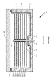
- FIG 2 shows a section view AA of the disk media storage system 100 of Figure 1 .
- the disk media storage system 100 in this example includes the media enclosure structure 110, the disk media chamber 113 formed in the media enclosure structure 110, and the spindle base 116 formed in the disk media chamber 113.
- the disk media chamber 113 in some examples is sealed and filled with a predetermined gas or gas mixture.
- the spindle base 116 includes the shaft bore 117, with the shaft bore 117 receiving the shaft 119 that rotates the one or more disk media 120.
- the one or more disk media 120 are located in the disk media chamber 113 and are coaxial with the shaft bore 117 of the spindle base 116.
- Spacers 121 are positioned between individual disk media 120.
- a top spacer 123 is located on a top disk of the one or more disk media 120, wherein the spacers 121 and the top spacer 123 hold the one or more disk media 120 in a predetermined spacing.
- the read/write head 130 is not shown for clarity.
- the cover 140 has been sealingly affixed to the media enclosure structure 110 in order to seal the media enclosure structure 110 and make the disk media storage system 100 substantially gas-tight.
- the non-porous coating 114 has been formed on an internal surface or surfaces of the disk media chamber 113. As before, the sealed disk media chamber 113 is filled with the predetermined gas or gas mixture.
- the non-porous coating 114 makes the media enclosure structure 110 substantially non-porous to gas molecules, even to small gas molecules such as helium gas molecules, for example. The predetermined gas or gas mixture therefore cannot diffuse through the media enclosure structure 110.
- the cover 140 can be welded to the media enclosure structure 110 in some examples, including laser welding or any other suitable welding type, as previously discussed.
- the size of the weld 170 is exaggerated in the figure for clarity.
- the weld 170 may be formed of material from the media enclosure structure 110 and/or the cover 140, and may not comprise externally supplied weld material.
- a seal 170 can be positioned between the media enclosure structure 110 and the cover 140.
- Figure 3 shows another section view AA of the disk media storage system 100 of Figure 1 .
- the disk media storage system 100 includes the non-porous coating 114 on an external surface or surfaces of the media enclosure structure 110.
- the disk media storage system 100 can optionally include the non-porous coating 114 on an external or internal surface or surfaces of the cover 140.
- the non-porous coating 114 performs the same function as in Figure 2 , preventing gas molecules from passing through and escaping from the media enclosure structure 110.
- the media enclosure structure 110 is also filled with a predetermined gas or gas mixture in order to minimize the effect of water and oxygen inside the disk media storage system 100.
- the media enclosure structure 110 can be sealed by the cover 140 affixed to the media enclosure structure 110.
- the cover 140 can be substantially non-porous to gas.
- the cover 140 can include the non-porous coating 114, as previously discussed.
- the non-porous coating 114 can be formed on the entire external surface or surfaces of the media enclosure structure 110.
- the non-porous coating 114 can be formed on external surfaces including the cover 140 and the weld or seal 170 (not shown).
- FIG. 4 shows another exemplary disk media storage system 400.
- the disk media storage system 400 in some examples comprises a Hard Disk Drive (HDD) that includes one or more disk media 420.
- the disk media storage system 400 includes a media enclosure structure 410, a disk media chamber 413 formed in a spindle base 416 formed in the media enclosure structure 410, a shaft bore 417 formed in the spindle base 416, one or more disk media 420 located in the disk media chamber 413 and coaxial with the shaft bore 417, one or more spacers 421 positioned between the disks 420, and a top spacer 423 located on a top disk of the one or more disk media 420.
- a read/write head 430 is located in the disk media chamber 413 and positioned to interact with the one or more disk media 420.
- Other components can be included in the disk media storage system 400, but are omitted for clarity.
- the disk media storage system 400 in this example additionally includes a first cover 440 and a second cover 450, instead of the single cover 140 of Figures 1-3 .
- the first cover 440 is sealingly affixed to the media enclosure structure 410.
- the second cover 450 likewise is sealingly affixed to the media enclosure structure 410 and is spaced-apart from the first cover 440.
- the first cover 440 forms a first chamber 443 within the disk media chamber 413.
- the first cover 440 and the second cover 450 together form a second chamber 453 within the disk media chamber 413.
- Figure 5 shows a section view BB of the disk media storage system 400 of Figure 4 .
- the disk media storage system 400 in this example includes a media enclosure structure 410, the first chamber 443 formed in the media enclosure structure 410, and the second chamber 453 formed in the media enclosure structure 410.
- Spacers 421 are positioned between individual disk media 420.
- a top spacer 423 is located on a top disk of the one or more disk media 420, wherein the spacers 421 and the top spacer 423 hold the one or more disk media 420 in a predetermined spacing.
- the read/write head 430 is not shown for clarity.
- the first cover 440 has been sealingly affixed to the media enclosure structure 410 in order to seal the media enclosure structure 410 and make the disk media storage system 400 substantially gas-tight.
- the first cover 440 can be affixed to a sidewall of the media enclosure structure 410, including to a shoulder 411 or projection in the sidewall.
- the non-porous coating 414 has been formed on an internal surface or surfaces of the first chamber 443 in this example.
- the sealed first chamber 443 is filled with a predetermined gas or gas mixture.
- the non-porous coating 414 makes the first chamber 443 substantially non-porous to gas, as previously discussed.
- the predetermined gas or gas mixture cannot diffuse through the media enclosure structure 410.
- the non-porous coating 414 can alternatively or additionally be formed on an external surface or surfaces of the media enclosure structure 410.
- the first cover 440 can be welded to the media enclosure structure 410 in some examples, including laser welding or any other suitable welding type, as previously discussed.
- the size of the weld 470 is exaggerated in the figure for clarity.
- the weld 470 may be formed of material from the media enclosure structure 410 and/or the first cover 440, and may not comprise externally supplied weld material in some examples.
- a seal (not shown) can be positioned between the media enclosure structure 410 and the first cover 440.
- non-porous coating 414 can optionally be formed on an internal surface or surfaces of the second chamber 453 in some examples. Consequently, the second chamber 453 can also be substantially non-porous to the predetermined gas or gas mixture.
- the second chamber 453 can be filled with a same gas or gas mixture as is sealed in the first chamber 443. Alternatively, the second chamber 453 can be filled with a different gas or gas mixture.
- the second chamber 453 can be filled with a gas or gas mixture that is at substantially the same pressure as the gas or gas mixture in the first chamber 443. Alternatively, the gas or gas mixture in the second chamber 453 can be at a different pressure than the gas or gas mixture in the first chamber 443.
- the second cover 450 has also been affixed to the media enclosure structure 410.
- the second cover 450 is sealingly affixed to the media enclosure structure 410, similar to the first cover 440.
- the second cover 450 is spaced-apart from the first cover 440 and forms the second chamber 453 between the first cover 440 and the second cover 450.
- the gas in the second chamber 453 can be at a same or different pressure from the gas in the first chamber 443 in order to reduce the possibility of air and/or moisture penetrating into the first chamber 443 and causing oxidization of the one or more disk media 420 (and/or other electronic components). Where the gas pressure in the second chamber 453 is greater than the gas pressure in the first chamber 443 (such as where the pressure in the first chamber 443 is less or much less than atmospheric pressure), there is less likelihood of gas in the second chamber 453 escaping to the outside.
- Figure 6 is a graph of a steel use stainless (SUS) cover plate, showing atomic content versus sputter time. The figure shows percent atomic content for both carbon (C) and oxygen (O). It can be seen in the graph that the oxygen level is significant.
- SUS steel use stainless
- Figure 7 is another graph of the SUS cover plate, wherein carbon content is much greater. Consequently, the oxygen level is greatly reduced in this scenario.
Landscapes
- Engineering & Computer Science (AREA)
- Manufacturing & Machinery (AREA)
- Chemical Vapour Deposition (AREA)
- Physical Vapour Deposition (AREA)
- Packaging For Recording Disks (AREA)
Applications Claiming Priority (1)
| Application Number | Priority Date | Filing Date | Title |
|---|---|---|---|
| US14/249,341 US20150294691A1 (en) | 2014-04-09 | 2014-04-09 | Sealed disk media enclosure |
Publications (2)
| Publication Number | Publication Date |
|---|---|
| EP2930718A2 true EP2930718A2 (de) | 2015-10-14 |
| EP2930718A3 EP2930718A3 (de) | 2016-03-23 |
Family
ID=53016457
Family Applications (1)
| Application Number | Title | Priority Date | Filing Date |
|---|---|---|---|
| EP15162838.5A Withdrawn EP2930718A3 (de) | 2014-04-09 | 2015-04-08 | Versiegeltes scheibenmediengehäuse |
Country Status (6)
| Country | Link |
|---|---|
| US (1) | US20150294691A1 (de) |
| EP (1) | EP2930718A3 (de) |
| JP (1) | JP2015201248A (de) |
| KR (1) | KR20150117229A (de) |
| CN (1) | CN105047217A (de) |
| SG (1) | SG10201502755RA (de) |
Families Citing this family (11)
| Publication number | Priority date | Publication date | Assignee | Title |
|---|---|---|---|---|
| CN105448308B (zh) | 2014-08-27 | 2019-04-09 | 祥和科技有限公司 | 用于形成具有延长高度的硬盘驱动器基板的方法和装置 |
| US10679680B2 (en) * | 2015-10-13 | 2020-06-09 | Seagate Technology Llc | Method and apparatus with multiple cavities |
| CN107799130B (zh) * | 2016-09-02 | 2019-09-06 | 株式会社东芝 | 盘装置及盘装置的制造方法 |
| JP2018160300A (ja) * | 2017-03-23 | 2018-10-11 | 株式会社東芝 | ディスク装置 |
| JP7135353B2 (ja) * | 2018-03-16 | 2022-09-13 | 日本電産株式会社 | ベースユニット、ディスク駆動装置、ベースユニットの製造方法、およびディスク駆動装置の製造方法 |
| US11020816B1 (en) * | 2018-09-05 | 2021-06-01 | Seagate Technology Llc | Methods of forming a friction stir weld between a steel piece and an aluminum piece, and related assemblies |
| US11783867B2 (en) | 2019-08-07 | 2023-10-10 | Seagate Technology Llc | Electronic device that includes a composition that can actively generate and release a gaseous oxidizing agent component into an interior space of the electronic device, and related subassemblies and methods |
| CN112337407A (zh) * | 2019-08-07 | 2021-02-09 | 希捷科技有限公司 | 包括生成气态氧化剂组分的组合物的电子设备以及方法 |
| US11763853B2 (en) | 2019-08-07 | 2023-09-19 | Seagate Technology Llc | Electronic device that includes a composition that can actively generate and release a gaseous oxidizing agent component into an interior space of the electronic device, and related subassemblies and methods |
| US11355161B2 (en) | 2019-08-07 | 2022-06-07 | Seagate Technology Llc | Electronic device that includes a composition that can release and optionally generate a gaseous oxidizing agent component into an interior space of the electronic device, and related subassemblies and methods |
| CN111402932B (zh) * | 2020-04-08 | 2021-08-10 | 杭州齐晨贸易有限公司 | 一种基于伯努利原理的磁盘检测设备 |
Family Cites Families (14)
| Publication number | Priority date | Publication date | Assignee | Title |
|---|---|---|---|---|
| JP2553316B2 (ja) * | 1993-03-02 | 1996-11-13 | インターナショナル・ビジネス・マシーンズ・コーポレイション | データ記憶ディスク・ドライブ装置 |
| US6410144B2 (en) * | 1995-03-08 | 2002-06-25 | Southwest Research Institute | Lubricious diamond-like carbon coatings |
| US6001481A (en) * | 1995-03-08 | 1999-12-14 | Southwest Research Institute | Porous anodized aluminum surfaces sealed with diamond-like carbon coatings |
| US7123440B2 (en) * | 2003-09-29 | 2006-10-17 | Hitachi Global Storage Technologies Netherlands B.V. | Hermetically sealed electronics arrangement and approach |
| US7538972B2 (en) * | 2004-05-25 | 2009-05-26 | 3M Innovative Properties Company | Internally replenished enclosure |
| JP4358700B2 (ja) * | 2004-07-28 | 2009-11-04 | ヒタチグローバルストレージテクノロジーズネザーランドビーブイ | ディスク装置及びその製造方法 |
| US8089721B1 (en) * | 2005-11-22 | 2012-01-03 | Seagate Technology Llc | Hermetic seal for discrete opening in disk drive housing |
| JP2008021743A (ja) * | 2006-07-11 | 2008-01-31 | Shin Etsu Polymer Co Ltd | 半導体ウェーハ収納容器 |
| JP5049017B2 (ja) * | 2007-01-05 | 2012-10-17 | エイチジーエスティーネザーランドビーブイ | 磁気ディスク装置及びその製造方法 |
| JP5043444B2 (ja) * | 2007-01-12 | 2012-10-10 | エイチジーエスティーネザーランドビーブイ | ディスク・ドライブ装置及びその製造方法 |
| JP5037438B2 (ja) * | 2008-06-19 | 2012-09-26 | エイチジーエスティーネザーランドビーブイ | ディスク・ドライブ及びディスク・ドライブの密閉筐体内に低密度ガスを再注入する方法 |
| JP2012000812A (ja) * | 2010-06-15 | 2012-01-05 | Daicel Corp | 積層フィルム及びその製造方法並びに電子デバイス |
| US8837080B2 (en) * | 2011-04-28 | 2014-09-16 | Entrotech, Inc. | Hard disk drives with composite housings and related methods |
| US8659849B2 (en) * | 2011-12-29 | 2014-02-25 | HGST Netherlands B.V. | Hermetically resealable hard-disk drive configured for recharging with a low-density gas |
-
2014
- 2014-04-09 US US14/249,341 patent/US20150294691A1/en not_active Abandoned
-
2015
- 2015-04-08 EP EP15162838.5A patent/EP2930718A3/de not_active Withdrawn
- 2015-04-08 SG SG10201502755RA patent/SG10201502755RA/en unknown
- 2015-04-09 CN CN201510271711.7A patent/CN105047217A/zh active Pending
- 2015-04-09 KR KR1020150050412A patent/KR20150117229A/ko not_active Ceased
- 2015-04-09 JP JP2015080136A patent/JP2015201248A/ja active Pending
Non-Patent Citations (1)
| Title |
|---|
| None |
Also Published As
| Publication number | Publication date |
|---|---|
| JP2015201248A (ja) | 2015-11-12 |
| US20150294691A1 (en) | 2015-10-15 |
| EP2930718A3 (de) | 2016-03-23 |
| SG10201502755RA (en) | 2015-11-27 |
| CN105047217A (zh) | 2015-11-11 |
| KR20150117229A (ko) | 2015-10-19 |
Similar Documents
| Publication | Publication Date | Title |
|---|---|---|
| US20150294691A1 (en) | Sealed disk media enclosure | |
| US6762909B2 (en) | Magnetic recording disk drive with self-limiting wearable contact pad air-bearing slider in hermetically sealed environment | |
| US8199425B1 (en) | Method to replace gas in a disk drive | |
| CN105632520B (zh) | 垂直磁记录介质及磁存储装置 | |
| JP2013033585A5 (de) | ||
| EP2469522A3 (de) | Optischer Kopf und Informationsaufzeichnungs-/Informationswiedergabevorrichtung | |
| JP2010106290A (ja) | 成膜装置および成膜方法、磁気記録媒体、磁気記録再生装置 | |
| JP2010092523A (ja) | インライン式成膜装置、磁気記録媒体の製造方法、及びゲートバルブ | |
| US9548075B2 (en) | Magnetic recording medium and magnetic recording/reproduction apparatus | |
| US20200279581A1 (en) | Magnetic recording medium and magnetic recording and reproducing device | |
| US9685184B1 (en) | NiFeX-based seed layer for magnetic recording media | |
| WO2000070106A1 (en) | Magnetic alloy and magnetic recording medium and method for preparation thereof, and target for forming magnetic film and magnetic recording device | |
| JP2010027102A (ja) | 磁気記録媒体およびその製造方法、磁気記録再生装置 | |
| JP2004280944A (ja) | 磁気記憶装置 | |
| Goodson | The adsorption of moisture on carbon films used as overcoats for rigid disk thin film magnetic recording media | |
| JP2004280941A (ja) | 磁気記憶装置 | |
| JPH0684169A (ja) | 磁気記録媒体およびその製造方法ならびに磁気ディスク装置 | |
| JP2004280946A (ja) | 磁気記憶装置 |
Legal Events
| Date | Code | Title | Description |
|---|---|---|---|
| PUAI | Public reference made under article 153(3) epc to a published international application that has entered the european phase |
Free format text: ORIGINAL CODE: 0009012 |
|
| AK | Designated contracting states |
Kind code of ref document: A2 Designated state(s): AL AT BE BG CH CY CZ DE DK EE ES FI FR GB GR HR HU IE IS IT LI LT LU LV MC MK MT NL NO PL PT RO RS SE SI SK SM TR |
|
| AX | Request for extension of the european patent |
Extension state: BA ME |
|
| PUAL | Search report despatched |
Free format text: ORIGINAL CODE: 0009013 |
|
| RIC1 | Information provided on ipc code assigned before grant |
Ipc: G11B 33/14 20060101AFI20160211BHEP Ipc: G11B 25/04 20060101ALI20160211BHEP Ipc: G11B 17/028 20060101ALI20160211BHEP |
|
| AK | Designated contracting states |
Kind code of ref document: A3 Designated state(s): AL AT BE BG CH CY CZ DE DK EE ES FI FR GB GR HR HU IE IS IT LI LT LU LV MC MK MT NL NO PL PT RO RS SE SI SK SM TR |
|
| AX | Request for extension of the european patent |
Extension state: BA ME |
|
| 17P | Request for examination filed |
Effective date: 20160923 |
|
| RBV | Designated contracting states (corrected) |
Designated state(s): AL AT BE BG CH CY CZ DE DK EE ES FI FR GB GR HR HU IE IS IT LI LT LU LV MC MK MT NL NO PL PT RO RS SE SI SK SM TR |
|
| STAA | Information on the status of an ep patent application or granted ep patent |
Free format text: STATUS: THE APPLICATION HAS BEEN WITHDRAWN |
|
| 18W | Application withdrawn |
Effective date: 20170210 |