EP2930372A1 - Trommelläufer-laufrad mit wuchttaschen - Google Patents
Trommelläufer-laufrad mit wuchttaschen Download PDFInfo
- Publication number
- EP2930372A1 EP2930372A1 EP15161266.0A EP15161266A EP2930372A1 EP 2930372 A1 EP2930372 A1 EP 2930372A1 EP 15161266 A EP15161266 A EP 15161266A EP 2930372 A1 EP2930372 A1 EP 2930372A1
- Authority
- EP
- European Patent Office
- Prior art keywords
- balancing
- bulge
- rotor wheel
- drum rotor
- Prior art date
- Legal status (The legal status is an assumption and is not a legal conclusion. Google has not performed a legal analysis and makes no representation as to the accuracy of the status listed.)
- Granted
Links
Images




Classifications
-
- F—MECHANICAL ENGINEERING; LIGHTING; HEATING; WEAPONS; BLASTING
- F01—MACHINES OR ENGINES IN GENERAL; ENGINE PLANTS IN GENERAL; STEAM ENGINES
- F01D—NON-POSITIVE DISPLACEMENT MACHINES OR ENGINES, e.g. STEAM TURBINES
- F01D5/00—Blades; Blade-carrying members; Heating, heat-insulating, cooling or antivibration means on the blades or the members
- F01D5/02—Blade-carrying members, e.g. rotors
- F01D5/027—Arrangements for balancing
-
- F—MECHANICAL ENGINEERING; LIGHTING; HEATING; WEAPONS; BLASTING
- F04—POSITIVE - DISPLACEMENT MACHINES FOR LIQUIDS; PUMPS FOR LIQUIDS OR ELASTIC FLUIDS
- F04D—NON-POSITIVE-DISPLACEMENT PUMPS
- F04D29/00—Details, component parts, or accessories
- F04D29/26—Rotors specially for elastic fluids
- F04D29/28—Rotors specially for elastic fluids for centrifugal or helico-centrifugal pumps for radial-flow or helico-centrifugal pumps
- F04D29/281—Rotors specially for elastic fluids for centrifugal or helico-centrifugal pumps for radial-flow or helico-centrifugal pumps for fans or blowers
- F04D29/282—Rotors specially for elastic fluids for centrifugal or helico-centrifugal pumps for radial-flow or helico-centrifugal pumps for fans or blowers the leading edge of each vane being substantially parallel to the rotation axis
-
- F—MECHANICAL ENGINEERING; LIGHTING; HEATING; WEAPONS; BLASTING
- F04—POSITIVE - DISPLACEMENT MACHINES FOR LIQUIDS; PUMPS FOR LIQUIDS OR ELASTIC FLUIDS
- F04D—NON-POSITIVE-DISPLACEMENT PUMPS
- F04D29/00—Details, component parts, or accessories
- F04D29/26—Rotors specially for elastic fluids
- F04D29/28—Rotors specially for elastic fluids for centrifugal or helico-centrifugal pumps for radial-flow or helico-centrifugal pumps
- F04D29/30—Vanes
-
- F—MECHANICAL ENGINEERING; LIGHTING; HEATING; WEAPONS; BLASTING
- F04—POSITIVE - DISPLACEMENT MACHINES FOR LIQUIDS; PUMPS FOR LIQUIDS OR ELASTIC FLUIDS
- F04D—NON-POSITIVE-DISPLACEMENT PUMPS
- F04D29/00—Details, component parts, or accessories
- F04D29/66—Combating cavitation, whirls, noise, vibration or the like; Balancing
- F04D29/661—Combating cavitation, whirls, noise, vibration or the like; Balancing especially adapted for elastic fluid pumps
- F04D29/662—Balancing of rotors
-
- F—MECHANICAL ENGINEERING; LIGHTING; HEATING; WEAPONS; BLASTING
- F04—POSITIVE - DISPLACEMENT MACHINES FOR LIQUIDS; PUMPS FOR LIQUIDS OR ELASTIC FLUIDS
- F04D—NON-POSITIVE-DISPLACEMENT PUMPS
- F04D29/00—Details, component parts, or accessories
- F04D29/66—Combating cavitation, whirls, noise, vibration or the like; Balancing
- F04D29/68—Combating cavitation, whirls, noise, vibration or the like; Balancing by influencing boundary layers
- F04D29/681—Combating cavitation, whirls, noise, vibration or the like; Balancing by influencing boundary layers especially adapted for elastic fluid pumps
-
- F—MECHANICAL ENGINEERING; LIGHTING; HEATING; WEAPONS; BLASTING
- F05—INDEXING SCHEMES RELATING TO ENGINES OR PUMPS IN VARIOUS SUBCLASSES OF CLASSES F01-F04
- F05D—INDEXING SCHEME FOR ASPECTS RELATING TO NON-POSITIVE-DISPLACEMENT MACHINES OR ENGINES, GAS-TURBINES OR JET-PROPULSION PLANTS
- F05D2240/00—Components
- F05D2240/20—Rotors
- F05D2240/30—Characteristics of rotor blades, i.e. of any element transforming dynamic fluid energy to or from rotational energy and being attached to a rotor
- F05D2240/306—Characteristics of rotor blades, i.e. of any element transforming dynamic fluid energy to or from rotational energy and being attached to a rotor related to the suction side of a rotor blade
Definitions
- the invention relates to a drum rotor wheel for a fan.
- Tumbler fans are radial flow machines with a rotor wheel having numerous short, forwardly curved blades. Due to the forward curved blading drum runners reach in terms of producible flow velocity and pressure increase in the flow medium desired operating points at significantly lower speeds than radial fan with backward curved blading, which is desired, for example, when used in air conditioning. The forward curvature causes a high energy transfer from the fan to the delivery fluid. Drum runners are used with a housing that converts the high kinetic energy into pressure energy. The flow enters axially into the fan, is accelerated and leaves the housing radially.
- the forward curvature of the blades is characterized by a strong flow deflection, wherein the flow can not follow the blade curvature in most cases and peels or flows back.
- the detachment bladder on the suction side of the blade thereby represents a loss area.
- the efficiency of such drum rotor fans is therefore relatively low. Nevertheless, the high power density and therefore the low installation space required has led to a widespread use in the field of heating, air conditioning and ventilation technology.
- Rotor impellers for blowers and fans usually need to be balanced for practical use to ensure smooth, low-vibration running.
- balancing weights are arranged above all on the outer periphery.
- a radial impeller arrangement with a backward curved radial impeller wheel with a circular bottom disk and circular cover disc with Einpressronde on at least one of the two discs in the disc edge area to attach at least one balance weight.
- the impeller can build larger by the balance weight.
- a two-piece balancing weight can be used, which has a spring clip and an additional weight, wherein the spring clip has a holding portion for attachment to the impeller and a receiving portion for holding the additional weight.
- Such balancing weights must be laboriously assembled. In particular, it is customary to mount balancing weights manually.
- the present invention is therefore based on the object to provide a Drummellellerrad that is easily balanced and automatically ausuchtbar is also manually balanced, the efficiency of the Trommelelerierrads should not be degraded.
- An inventive drum rotor wheel has numerous short, forwardly curved blades.
- the blades have a suction side and a pressure side.
- a cover plate and a bottom plate are provided at the Trommelrellerrad.
- At least one blade of the drum rotor wheel has a bulge on its suction side. The bulge minimizes the area of flow separation, thereby also minimizing the amount of flow separation. In other words, the efficiency of the Trommelelpitrrads is increased by the bulge.
- the bulge is connected to the bottom plate.
- the stability of the blade provided with the bulge is positively influenced by the enlarged connection via the bulge to the bottom plate and the efficiency of the Trommeleltechnikrrads not deteriorated.
- the bulge is completely provided in the field of flow separation. If the bulge lies only in the region of the flow separation, but substantially completely fills it, the vortex formation is almost completely prevented and the efficiency of the drum rotor wheel is optimized. On the other hand, the maximum cross section for the flow between the blades is available, whereby the flow resistance is minimized and the efficiency of the Trommeleltechnikrrads is further optimized.
- the balancing bag is designed in a hollow shape for receiving a balancing weight. Characterized in that the balancing pocket extends into the bottom plate and is guided through it, it has an opening in the bottom plate through which a balancing weight can be spent in the balancing bag. In particular, it is possible in an open design of the balancing pocket to automatically spend a balance weight in the balancing bag.
- the balancing bag can be designed so that a rectangular plug-in weight for balancing can be pressed into the balancing pocket in a form-fitting manner.
- Tumbler wheels are usually made of plastics, especially thermoplastics and mainly by injection molding.
- Tumbler wheels are usually made of plastics, especially thermoplastics and mainly by injection molding.
- the problem arises that sinking points and / or voids occur due to the shrinkage of the plastic during the cooling, which weaken the mechanical stability of the molding and can result in a contour change.
- the shape of the bulge may deviate from the intended shape, which again dead water areas can occur in the flow during operation, which can reduce the efficiency of the Trommelzustäuferrads.
- This risk is significantly reduced.
- material is saved.
- the bulge in the axial direction x is made shorter than the axial extent of the blade.
- the balancing pocket extends into the cover disk.
- the bulge extends over the entire height of the blade.
- a correspondingly increased balance weight can be spent, whereby the balancing effect can be increased.
- the balancing pocket is guided through the cover disk.
- an opening of the balancing pocket is achieved in the cover plate, whereby a balancing weight can be brought into the balancing pocket.
- this embodiment provides an additional feeding possibility for a balancing weight, which is advantageous in the case of an automated balancing of the feed through the bottom disk, since the flexibility of the supply of a balancing weight is increased. If, for example, due to geometric conditions on the balancing machine, no balancing weight can be supplied through the bottom disk, in this embodiment the balancing weight can alternatively be introduced through the cover disk.
- all blades have a bulge. This minimizes flow separation on all blades, further increasing the efficiency of the entire drum rotor wheel.
- the balancing quality can be increased since the location of a balancing weight required for optimal balancing can be more accurately determined.
- the cover disc has an additional ring on its outer side, wherein the inner contour of the additional ring has a radius-shaped region.
- the radius-shaped area on the inner contour of the ring allows a guided deflection of the flow and further minimizes the flow losses, whereby the efficiency of the Trommeleltechnikrrads is further increased.
- the additional ring has at least one second balancing pocket.
- a second level is still obtained for the balance, whereby the balancing quality is improved.
- Fig. 1 shows a flow pattern on a Trommelellibraryrrad 10 according to the prior art.
- the blades 20 are curved forward with great curvature.
- the flow can not follow the high curvature and dissolves on the suction side 21 of the blades 20, creating an area 25 of flow separation, which causes vortex formation in this area 25, causing losses due to dissipation.
- Fig. 2 shows a drum pulley 10 according to the invention in a three-dimensional view from the perspective of the cover plate 30.
- the drum rotor 10 has numerous short, forward curved blades 20.
- the blades 20 have a suction side 21 and a pressure side 22.
- the blades 20 of the Drummelêtrrads 10 have on their suction side 21 bulges 23.
- the area 25 in Fig. 1 minimizes flow separation on each blade 20, thereby also minimizing the amount of total flow separation.
- the bulges 23 are connected to the bottom plate 40 and made shorter in the axial direction x than the axial extent of the blade 20 itself.
- the cover plate 30 has an additional ring 31.
- This additional ring 31 has second balancing pockets 33.
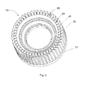
- Fig. 3 shows a drum rotor 10 according to the invention in a three-dimensional representation from the perspective of the bottom plate 40.
- the drum rotor 10 is made for example of a thermoplastic material by injection molding.
- the bulge 23 (in Fig. 3 not visible) on the blades 20 of the Drummel culminrrads 10 have balancing pockets 24 which extend into the bottom plate 40 into and are guided therethrough.
- the balancing pockets 24 are hollow shaped, so that they can take balancing weights. Characterized in that the balancing pockets 24 extend into the bottom plate 40 and are guided through them, they have openings 41 in the bottom plate 40, can be spent by the balancing weights in the balancing pockets 24.
- Fig. 4 shows the Drummell 10 in longitudinal section.
- the cover plate 30 has an additional ring 31.
- This additional ring 31 has a second balancing pocket 33.
- the second balancing pockets 33 in the additional ring 31 is still a second level for the balance obtained the balancing quality can be improved.
- the additional ring 31 has below the second balancing pocket 33 in the opposite x-direction an annular material cut with a radius-shaped region 32.
- Fig. 5 shows the section C - C through the bulges 23 of the blades 20 on the bottom plate 40 of a Trommeleltechnikrrads 10.
- the bulges 23 have substantially a contour, that of the area 25 of the flow separation from Fig. 1 equivalent.
- the balancing pockets 24 have, for example, a rectangular cross section, so that suitable rectangular balancing weights can be pressed into the balancing pockets 24 in a form-fitting manner. Other balancing pocket and balancing weights geometries are also possible.
- Fig. 6 shows a flow pattern on a drum rotor 10 according to the invention.
- the bulge 23 is completely provided in the region 25 of the flow separation. If the bulge 23 is only in the region 25 of the flow separation, but substantially completely fills it, the vortex formation is almost completely prevented, as can be seen from the vortex arrows, and the efficiency of the Trommeleltechnikrrads 10 is optimized.
Landscapes
- Engineering & Computer Science (AREA)
- Mechanical Engineering (AREA)
- General Engineering & Computer Science (AREA)
- Structures Of Non-Positive Displacement Pumps (AREA)
- Centrifugal Separators (AREA)
- Turbine Rotor Nozzle Sealing (AREA)
Abstract
Description
- Die Erfindung betrifft ein Trommelläuferrad für einen Lüfter.
- Trommelläufer-Lüfter sind radiale Strömungsmaschinen mit einem Läuferrad, das zahlreiche kurze, vorwärts gekrümmte Schaufeln aufweist. Durch die vorwärtsgekrümmte Beschaufelung erreichen Trommelläufer hinsichtlich erzeugbarer Strömungsgeschwindigkeit und Druckerhöhung im Strömungsmedium gewünschte Betriebspunkte bei deutlich niedrigeren Drehzahlen als Radiallüfter mit rückwärtsgekrümmter Beschaufelung, was beispielsweise bei der Verwendung in Klimaanlagen gewünscht ist. Die Vorwärtskrümmung bewirkt einen hohen Energietransfer vom Lüfter auf das Förderfluid. Trommelläufer werden mit einem Gehäuse verwendet, welches die hohe kinetische Energie in Druckenergie umwandelt. Die Strömung tritt axial in den Lüfter ein, wird beschleunigt und verlässt radial das Gehäuse. Die Vorwärtskrümmung der Schaufeln ist geprägt von einer starken Strömungsumlenkung, wobei die Strömung in den meisten Fällen der Schaufelkrümmung nicht folgen kann und ablöst beziehungsweise rückströmt. Die Ablöseblase auf der Saugseite der Schaufel stellt dabei ein Verlustgebiet dar. Der Wirkungsgrad solcher Trommelläufer-Lüfter ist daher relativ niedrig. Dennoch hat die hohe Leistungsdichte und der daher benötigte geringe Bauraum zu einer starken Verbreitung im Bereich der Heizungs-, Klima- und Lüftungstechnik geführt.
- Läuferräder für Gebläse und Lüfter müssen in aller Regel für den praktischen Einsatz ausgewuchtet werden, um einen ruhigen, schwingungsarmen Lauf zu gewährleisten. Dazu werden vor allem an der äußeren Peripherie Wuchtgewichte angeordnet.
- Beispielsweise ist es möglich, an einer Radial-Läuferrad-Anordnung mit einem rückwärts gekrümmten Radialläuferrad mit kreisförmiger Bodenscheibe und kreisförmiger Deckscheibe mit Einpressronde auf mindestens einer der beiden Scheiben im Scheibenrandbereich mindestens ein Ausgleichgewicht zu befestigen. Dabei kann das Läuferrad durch das Ausgleichsgewicht größer bauen. Beispielsweise kann ein zweiteiliges Wuchtgewicht verwendet werden, das eine Federklammer und ein Zusatzgewicht aufweist, wobei die Federklammer einen Halteabschnitt zum Befestigen an dem Laufrad und einen Aufnahmeabschnitt zur Halterung des Zusatzgewichtes aufweist. Solche Wuchtgewichte müssen aufwändig montiert werden. Insbesondere ist es üblich, Wuchtgewichte manuell zu montieren.
- Der vorliegenden Erfindung liegt daher die Aufgabe zu Grunde, ein Trommelläuferrad anzugeben, das auf einfache Weise automatisiert auswuchtbar ist als auch manuell auswuchtbar ist, wobei der Wirkungsgrad des Trommelläuferrads nicht verschlechtert werden soll.
- Erfindungsgemäß wird diese Aufgabe durch ein Trommelläuferrad mit den Merkmalen des unabhängigen Anspruches 1 gelöst. Vorteilhafte Weiterbildungen des Trommelläuferrads ergeben sich aus den Unteransprüchen 2 - 9.
- Ein erfindungsgemäßes Trommelläuferrad weist zahlreiche kurze, vorwärts gekrümmte Schaufeln auf. Die Schaufeln haben eine Saugseite und eine Druckseite. An dem Trommelläuferrad sind eine Deckscheibe und eine Bodenscheibe vorgesehen. Zumindest eine Schaufel des Trommelläuferrads weist auf ihrer Saugseite eine Auswölbung auf. Durch die Auswölbung wird das Gebiet der Strömungsablösung minimiert, wodurch das Ausmaß der Strömungsablösung ebenfalls minimiert wird. Mit anderen Worten wird durch die Auswölbung der Wirkungsgrad des Trommelläuferrads erhöht.
- Die Auswölbung ist mit der Bodenscheibe verbunden. Dadurch wird die Stabilität der mit der Auswölbung versehenen Schaufel durch die über die Auswölbung vergrößerte Anbindung an die Bodenscheibe positiv beeinflusst und der Wirkungsgrad des Trommelläuferrads nicht verschlechtert.
- Weiterhin ist die Auswölbung vollständig im Gebiet der Strömungsablösung vorgesehen. Wenn die Auswölbung nur im Bereich der Strömungsablösung liegt, diesen aber im Wesentlichen vollständig ausfüllt, ist die Wirbelbildung nahezu vollständig verhindert und der Wirkungsgrad des Trommelläuferrads optimiert. Andererseits steht der maximale Querschnitt für die Durchströmung zwischen den Schaufeln zu Verfügung, wodurch der Strömungswiderstand minimiert und der Wirkungsgrad des Trommelläuferrads weiter optimiert wird.
- In einer vorteilhaften Ausführungsform weist die Auswölbung an einer Schaufel des Trommelläuferrads wenigstens eine Wuchttasche auf, die bis in die Bodenscheibe hinein reicht und durch sie hindurch geführt ist. Die Wuchttasche ist hohlförmig zur Aufnahme eines Wuchtgewichts ausgestaltet. Dadurch, dass die Wuchttasche bis in die Bodenscheibe hinein reicht und durch sie hindurch geführt ist, weist sie eine Öffnung in der Bodenscheibe auf, durch die ein Wuchtgewicht in die Wuchttasche verbracht werden kann. Insbesondere ist es bei einer offenen Ausgestaltung der Wuchttasche möglich, ein Wuchtgewicht automatisiert in die Wuchttasche zu verbringen. Beispielsweise kann die Wuchttasche so gestaltet werden, dass ein rechteckiges Steckgewicht zur Auswuchtung formschlüssig in die Wuchttasche einpressbar ist. Eine solche Ausgestaltung eignet sich besonders gut für die automatisierte Auswuchtung von Trommelläuferrädern. Darüber hinaus wird durch die hohle Gestaltung der Auswölbung eine Materialanhäufung minimiert. Trommelläuferräder werden üblicherweise aus Kunststoffen, insbesondere thermoplastischen Kunststoffen und hauptsächlich im Spritzgußverfahren hergestellt. Bei Materialanhäufungen von im Spritzgußverfahren hergestellten Kunststoffteilen tritt das Problem auf, dass durch die Schwindung des Kunststoffs während der Erkaltung Einfallstellen und/oder Lunker auftreten, die die mechanische Stabilität des Formteils schwächen und eine Konturveränderung zur Folge haben können. Durch eine solche Konturveränderung kann die Form der Auswölbung von der vorgesehen Form abweichen, wodurch im Betrieb erneut Totwassergebiete in der Strömung auftreten können, die den Wirkungsgrad des Trommelläuferrads verringern können. Durch das Vorsehen einer Wuchttasche in der Auswölbung wird diese Gefahr deutlich verringert. Darüber hinaus wird Material eingespart.
- In einer weiteren Ausführungsform ist die Auswölbung in axialer Richtung x kürzer ausgeführt als die axiale Ausdehnung der Schaufel.
- In einer alternativen Ausführungsform reicht die Wuchttasche bis in die Deckscheibe hinein. Dabei erstreckt sich die Auswölbung über die gesamte Höhe der Schaufel. In eine derart vergrößerte Wuchttasche lässt sich ein entsprechend vergrößertes Wuchtgewicht verbringen, wodurch der Auswuchteffekt vergrößert werden kann.
- In einer vorteilhaften Ausführungsform ist die Wuchttasche durch die Deckscheibe hindurch geführt. Hierdurch wird eine Öffnung der Wuchttasche in der Deckscheibe erreicht, wodurch ein Wuchtgewicht in die Wuchttasche verbringbar ist. Insbesondere eröffnet diese Ausführungsform eine zu der Zuführung durch die Bodenscheibe zusätzliche Zuführungsmöglichkeit für ein Wuchtgewicht, was bei einer automatisierten Wuchtung vorteilhaft ist, da die Flexibilität der Zuführung eines Wuchtgewichts erhöht wird. Kann beispielsweise aus geometrischen Gegebenheiten an der Wuchtmaschine kein Wuchtgewicht durch die Bodenscheibe zugeführt werden, kann in dieser Ausführungsform das Wuchtgewicht alternativ durch die Deckscheibe eingebracht werden.
- In einer vorteilhaften Ausführungsform weisen alle Schaufeln eine Auswölbung auf. Dadurch wird eine Strömungsablösung an allen Schaufern minimiert, wodurch der Wirkungsgrad des gesamten Trommelläuferrads weiter steigt. Weisen darüber hinaus mehrere Auswölbungen Wuchttaschen auf, lässt sich die Wuchtqualität erhöhen, da der für eine optimale Auswuchtung erforderliche Anbringungsort eines Wuchtgewichts sich genauer treffen lässt.
- Es hat sich als besonders vorteilhaft erwiesen, wenn die Auswölbung vollständig im Gebiet der Strömungsablösung vorgesehen ist. Der Wirkungsgrad des Trommelläuferrads wird hierdurch weiter erhöht, wobei gleichzeitig ein maximierter Durchströmungsquerschnitt zur Verfügung gestellt wird.
- Eine noch weitere Erhöhung des Wirkungsgrads des Trommelläuferrads lässt sich erreichen, wenn die Auswölbung in radialer Richtung im Wesentlichen der Form des Gebiets der Strömungsablösung entspricht.
- In einer weiteren vorteilhaften Ausführungsform weist die Deckscheibe einen zusätzlichen Ring auf ihrer Außenseite auf, wobei die Innenkontur des zusätzlichen Rings einen radiusförmigen Bereich aufweist. Der radiusförmige Bereich an der Innenkontur des Rings ermöglicht eine geführte Umlenkung der Strömung und minimiert weiter die Strömungsverluste, wodurch der Wirkungsgrad des Trommelläuferrads weiter erhöht wird.
- Es hat sich weiterhin als vorteilhaft erwiesen, wenn der zusätzliche Ring mindestens eine zweite Wuchttasche aufweist. In den Fällen, in denen zu der Gestaltung der Wuchttasche auf der Bodenscheibenseite eine Wuchttaschengestaltung auf der Deckscheibe nicht möglich ist, wird dennoch eine zweite Ebene für die Wuchtung erhalten, wodurch die Wuchtqualität verbesserbar ist.
- In einer weiteren vorteilhaften Ausführungsform weist der zusätzliche Ring unterhalb der zweiten Wuchttasche einen ringförmigen Materialausschnitt auf, um durch die Materialreduzierung ein verbessertes Verzugsverhalten zu unterstützen.
- Weitere Vorteile, Besonderheiten und zweckmäßige Weiterbildungen der Erfindung ergeben sich aus den Unteransprüchen und der nachfolgenden Darstellung bevorzugter Ausführungsbeispiele anhand der Abbildungen.
- Von den Abbildungen zeigt:
- Fig. 1
- Strömungsbild an einem Trommelläuferrad nach dem Stand der Technik
- Fig. 2
- erfindungsgemäßes Trommelläuferrad in dreidimensionaler Darstellung aus Sicht der Deckscheibe
- Fig. 3
- erfindungsgemäßes Trommelläuferrad in dreidimensionaler Darstellung aus Sicht der Bodenscheibe
- Fig. 4
- Erfindungsgemäßes Trommelläuferrad im Längsschnitt
- Fig. 5
- Schnitt C-C durch die Auswölbungen der Schaufeln an der Bodenscheibe des erfindungsgemäßen Trommelläuferrads
- Fig. 6
- Wirbelbild an einem erfindungsgemäßen Trommelläuferrad
-
Fig. 1 zeigt ein Strömungsbild an einem Trommelläuferrad 10 nach dem Stand der Technik. Die Schaufeln 20 sind mit starker Krümmung vorwärts gekrümmt. Die Strömung kann der starken Krümmung nicht folgen und löst sich an der Saugseite 21 der Schaufeln 20 ab, so dass ein Gebiet 25 der Strömungsablösung entsteht, wobei es in diesem Gebiet 25 zu einer Wirbelbildung kommt, wodurch Verluste durch Dissipation verursacht werden. -
Fig. 2 zeigt ein erfindungsgemäßes Trommelläuferrad 10 in dreidimensionaler Darstellung aus Sicht der Deckscheibe 30. Das Trommelläuferrad 10 weist zahlreiche kurze, vorwärts gekrümmte Schaufeln 20 auf. Die Schaufeln 20 haben eine Saugseite 21 und eine Druckseite 22. An dem Trommelläuferrad 10 sind eine Deckscheibe 30 und eine Bodenscheibe 40 vorgesehen. Die Schaufeln 20 des Trommelläuferrads 10 weisen an ihrer Saugseite 21 Auswölbungen 23 auf. Durch die Auswölbung 23 wird das Gebiet 25 inFig. 1 der Strömungsablösung an jeder Schaufel 20 minimiert, wodurch das Ausmaß der gesamten Strömungsablösung ebenfalls minimiert wird. Die Auswölbungen 23 sind mit der Bodenscheibe 40 verbunden und in axialer Richtung x kürzer ausgeführt als die axiale Ausdehnung der Schaufel 20 selbst. - Die Deckscheibe 30 weist einen zusätzlichen Ring 31 auf. Dieser zusätzliche Ring 31 weist zweite Wuchttaschen 33 auf.
-
Fig. 3 zeigt ein erfindungsgemäßes Trommelläuferrad 10 in dreidimensionaler Darstellung aus Sicht der Bodenscheibe 40. Das Trommelläuferrad 10 ist beispielsweise aus einem thermoplastischen Kunststoff im Spritzgußverfahren hergestellt. Die Auswölbung 23 (inFig. 3 nicht sichtbar) an den Schaufeln 20 des Trommelläuferrads 10 weisen Wuchttaschen 24 auf, die bis in die Bodenscheibe 40 hinein reichen und durch sie hindurch geführt sind. Die Wuchttaschen 24 sind hohlförmig ausgestaltet, so dass sie Wuchtgewichte aufnehmen können. Dadurch, dass die Wuchttaschen 24 bis in die Bodenscheibe 40 hinein reichen und durch sie hindurch geführt sind, weisen sie Öffnungen 41 in der Bodenscheibe 40 auf, durch die Wuchtgewichte in die Wuchttaschen 24 verbracht werden können. -
Fig. 4 zeigt das Trommelläuferrad 10 im Längsschnitt. Die Deckscheibe 30 weist einen zusätzlichen Ring 31 auf. Dieser zusätzliche Ring 31 weist eine zweite Wuchttasche 33 auf. In den Fällen, in denen eine zu der Gestaltung der Wuchttasche 24 auf der Seite der Bodenscheibe 40 analoge Gestaltung auf der Deckscheibe 30 nicht möglich ist, wird mit den zweiten Wuchttaschen 33 in dem zusätzlichen Ring 31 dennoch eine zweite Ebene für die Wuchtung erhalten, wodurch die Wuchtqualität verbesserbar ist. Der zusätzliche Ring 31 weist unterhalb der zweiten Wuchttasche 33 in entgegengesetzter x-Richtung einen ringförmigen Materialschnitt mit einem radiusförmigen Bereich 32 auf. Hierdurch wird die Einlaufströmung so geführt, dass keine Strömungsverluste auftreten und der Wirkungsgrad des Trommelläuferrads weiter optimiert wird. -
Fig. 5 zeigt den Schnitt C - C durch die Auswölbungen 23 der Schaufeln 20 an der Bodenscheibe 40 eines Trommelläuferrads 10. Die Auswölbungen 23 weisen im Wesentlichen eine Kontur auf, die der des Gebiets 25 der Strömungsablösung ausFig. 1 entspricht. Die Wuchttaschen 24 weisen beispielsweise einen rechteckigen Querschnitt auf, so dass geeignete rechteckige Wuchtgewichte formschlüssig in die Wuchttaschen 24 einpressbar sind. Andere Wuchttaschen- und Wuchtgewichtgeometrien sind ebenfalls möglich. -
Fig. 6 zeigt ein Strömungsbild an einem erfindungsgemäßen Trommelläuferrad 10. Dabei ist die Auswölbung 23 vollständig im Gebiet 25 der Strömungsablösung vorgesehen. Wenn die Auswölbung 23 nur im Bereich 25 der Strömungsablösung liegt, diesen aber im Wesentlichen vollständig ausfüllt, ist die Wirbelbildung nahezu vollständig verhindert, wie anhand der Wirbelpfeile erkennbar, und der Wirkungsgrad des Trommelläuferrads 10 ist optimiert. - Der Einsatz unterschiedlicher Materialien für die Schaufeln 20 ist in den
Fig. 1 bis 6 nicht gezeigt. - Die hier gezeigten Ausführungsformen stellen nur Beispiele für die vorliegende Erfindung dar und dürfen daher nicht einschränkend verstanden werden. Alternative durch den Fachmann in Erwägung gezogene Ausführungsformen sind gleichermaßen vom Schutzbereich der vorliegenden Erfindung umfasst.
-
- 10
- Trommelläuferrad
- 20
- Schaufel
- 21
- Saugseite
- 22
- Druckseite
- 23
- Auswölbung
- 24
- Wuchttasche
- 25
- Gebiet der Strömungsablösung
- 30
- Deckscheibe
- 31
- Ring
- 32
- radiusförmiger Bereich
- 33
- zweite Wuchttasche
- 40
- Bodenscheibe
- 41
- Öffnung
- x
- axiale Richtung
Claims (9)
- Trommelläuferrad (10), aufweisend zahlreiche kurze, vorwärts gekrümmte Schaufeln (20), wobei die Schaufeln (20) eine Saugseite (21) und eine Druckseite (22) aufweisen, eine Deckscheibe (30) und eine Bodenscheibe (40),
dadurch gekennzeichnet,
dass das Trommelläuferrad (10) zumindest eine Schaufel (20) aufweist, die auf ihrer Saugseite (21) eine Auswölbung (23) aufweist, wobei die Auswölbung (23) mit der Bodenscheibe (40) verbunden ist und die Auswölbung (23) vollständig im Gebiet der Strömungsablösung (25) vorgesehen ist und die Auswölbung (23) weiterhin eine Wuchttasche (24) aufweist, die bis in die Bodenscheibe (40) hinein reicht und durch sie hindurch geführt ist - Trommelläuferrad (10) nach Anspruch 1,
dadurch gekennzeichnet,
dass die Auswölbung (23) in axialer Richtung x kürzer ausgeführt ist als die axiale Ausdehnung der Schaufel (20). - Trommelläuferrad (10) nach Anspruch 1,
dadurch gekennzeichnet,
dass die Wuchttasche (24) bis in die Deckscheibe (30) hinein reicht. - Trommelläuferrad (10) nach Anspruch 3,
dadurch gekennzeichnet,
dass die Wuchttasche (24) durch die Deckscheibe (30) hindurch geführt ist. - Trommelläuferrad (10) nach einem der vorherigen Ansprüche,
dadurch gekennzeichnet,
dass alle Schaufeln (20) eine Auswölbung (23) aufweisen. - Trommelläuferrad (10) nach einem der vorherigen Ansprüche,
dadurch gekennzeichnet,
dass die Auswölbung (23) in radialer Richtung im Wesentlichen der Form des Gebiets der Strömungsablösung (25) entspricht. - Trommelläuferrad (10) nach einem der vorherigen Ansprüche,
dadurch gekennzeichnet,
dass die Deckscheibe (30) einen zusätzlichen Ring (31) auf ihrer Außenseite aufweist, wobei die Innenkontur des zusätzlichen Rings (31) einen radiusförmigen Bereich (32) aufweist. - Trommelläuferrad (10) nach Anspruch 7,
dadurch gekennzeichnet,
dass der zusätzliche Ring (31) mindestens eine zweite Wuchttasche (33) aufweist. - Trommelläuferrad (10) nach Anspruch 8,
dadurch gekennzeichnet,
dass der zusätzliche Ring (31) unterhalb der zweiten Wuchttasche (33) in entgegengesetzter x-Richtung einen ringförmigen Materialschnitt aufweist.
Priority Applications (1)
| Application Number | Priority Date | Filing Date | Title |
|---|---|---|---|
| SI201530134T SI2930372T1 (en) | 2014-04-11 | 2015-03-27 | Wheel of drum rotor with center pockets |
Applications Claiming Priority (2)
| Application Number | Priority Date | Filing Date | Title |
|---|---|---|---|
| DE102014207059 | 2014-04-11 | ||
| DE102014208372.9A DE102014208372A1 (de) | 2014-04-11 | 2014-05-05 | Wuchttaschen |
Publications (2)
| Publication Number | Publication Date |
|---|---|
| EP2930372A1 true EP2930372A1 (de) | 2015-10-14 |
| EP2930372B1 EP2930372B1 (de) | 2017-09-27 |
Family
ID=53058897
Family Applications (1)
| Application Number | Title | Priority Date | Filing Date |
|---|---|---|---|
| EP15161266.0A Active EP2930372B1 (de) | 2014-04-11 | 2015-03-27 | Trommelläufer-laufrad mit wuchttaschen |
Country Status (7)
| Country | Link |
|---|---|
| US (1) | US9909423B2 (de) |
| EP (1) | EP2930372B1 (de) |
| CN (2) | CN204828033U (de) |
| DE (2) | DE102014208372A1 (de) |
| ES (1) | ES2653529T3 (de) |
| HU (1) | HUE037743T2 (de) |
| SI (1) | SI2930372T1 (de) |
Families Citing this family (3)
| Publication number | Priority date | Publication date | Assignee | Title |
|---|---|---|---|---|
| USD771235S1 (en) * | 2014-04-11 | 2016-11-08 | Ebm-Papst Mulfingen Gmbh & Co. Kg | Fan drum rotor |
| US11105203B2 (en) | 2018-01-29 | 2021-08-31 | Carrier Corporation | High efficiency centrifugal impeller with balancing weights |
| TWI681127B (zh) * | 2018-02-01 | 2020-01-01 | 大陸商佛山市建準電子有限公司 | 離心扇及其扇輪 |
Citations (3)
| Publication number | Priority date | Publication date | Assignee | Title |
|---|---|---|---|---|
| DE202009006872U1 (de) * | 2008-05-27 | 2009-10-29 | Ebm-Papst St. Georgen Gmbh & Co. Kg | Radiallüfter |
| DE102009032411A1 (de) * | 2008-07-25 | 2010-02-04 | Denso Corporation, Kariya-City | Zentrifugales Mehrfachblatt-Gebläse |
| DE102011000208A1 (de) * | 2011-01-19 | 2012-07-19 | Minebea Co., Ltd. | Laufrad für ein Gebläse |
Family Cites Families (9)
| Publication number | Priority date | Publication date | Assignee | Title |
|---|---|---|---|---|
| JPS5331206A (en) * | 1976-09-06 | 1978-03-24 | Hitachi Ltd | Fan with forward blades |
| DE4136293B4 (de) * | 1990-11-03 | 2004-08-26 | Papst Licensing Gmbh & Co. Kg | Laufrad für ein Gebläse, insbesondere Radialgebläse |
| US6042335A (en) * | 1998-05-04 | 2000-03-28 | Carrier Corporation | Centrifugal flow fan and fan/orifice assembly |
| JP2006077723A (ja) * | 2004-09-13 | 2006-03-23 | Matsushita Electric Ind Co Ltd | 多翼ファン |
| US8337157B2 (en) * | 2005-07-04 | 2012-12-25 | Behr Gmbh & Co. Kg | Blower wheel |
| US8167562B2 (en) * | 2007-06-29 | 2012-05-01 | Denso Corporation | Centrifugal fan and blower having the same |
| JP5634782B2 (ja) * | 2009-08-11 | 2014-12-03 | 山洋電気株式会社 | 遠心ファン |
| JP5287772B2 (ja) * | 2010-03-16 | 2013-09-11 | 株式会社デンソー | 遠心式多翼ファン |
| DE202012103554U1 (de) * | 2012-09-18 | 2013-12-20 | Ebm-Papst Mulfingen Gmbh & Co. Kg | Laufrad mit Wuchtausgleich |
-
2014
- 2014-05-05 DE DE102014208372.9A patent/DE102014208372A1/de not_active Withdrawn
-
2015
- 2015-03-09 US US14/642,215 patent/US9909423B2/en active Active
- 2015-03-26 CN CN201520176422.4U patent/CN204828033U/zh not_active Expired - Lifetime
- 2015-03-26 CN CN201510137716.0A patent/CN104976151A/zh active Pending
- 2015-03-27 HU HUE15161266A patent/HUE037743T2/hu unknown
- 2015-03-27 EP EP15161266.0A patent/EP2930372B1/de active Active
- 2015-03-27 SI SI201530134T patent/SI2930372T1/en unknown
- 2015-03-27 ES ES15161266.0T patent/ES2653529T3/es active Active
- 2015-03-27 DE DE202015101563.1U patent/DE202015101563U1/de not_active Expired - Lifetime
Patent Citations (3)
| Publication number | Priority date | Publication date | Assignee | Title |
|---|---|---|---|---|
| DE202009006872U1 (de) * | 2008-05-27 | 2009-10-29 | Ebm-Papst St. Georgen Gmbh & Co. Kg | Radiallüfter |
| DE102009032411A1 (de) * | 2008-07-25 | 2010-02-04 | Denso Corporation, Kariya-City | Zentrifugales Mehrfachblatt-Gebläse |
| DE102011000208A1 (de) * | 2011-01-19 | 2012-07-19 | Minebea Co., Ltd. | Laufrad für ein Gebläse |
Also Published As
| Publication number | Publication date |
|---|---|
| HUE037743T2 (hu) | 2018-09-28 |
| EP2930372B1 (de) | 2017-09-27 |
| US9909423B2 (en) | 2018-03-06 |
| DE202015101563U1 (de) | 2015-04-28 |
| ES2653529T3 (es) | 2018-02-07 |
| US20150292331A1 (en) | 2015-10-15 |
| DE102014208372A1 (de) | 2015-10-15 |
| CN204828033U (zh) | 2015-12-02 |
| CN104976151A (zh) | 2015-10-14 |
| SI2930372T1 (en) | 2018-01-31 |
Similar Documents
| Publication | Publication Date | Title |
|---|---|---|
| EP2211444B1 (de) | Elektromotor mit Kühlventilatorwirkung | |
| EP2737189B1 (de) | Kühlerlüftermodul | |
| EP3031132B1 (de) | Rotornabenanordnung, elektrischer lüfter | |
| DE102013101133B4 (de) | Gebläsebaugruppe | |
| DE2754897A1 (de) | Ventilatoranordnung mit motorantrieb | |
| DE102013111889A1 (de) | Lüfterrad für Radiallüfter und Radiallüfter | |
| EP2549116A1 (de) | Axiallüfter mit zusätzlichem Strömungskanal | |
| DE112017000980T5 (de) | Radiallüfter | |
| DE102011013040A1 (de) | Zentrifugaler Mehrfachschaufel-Lüfter | |
| EP2930372B1 (de) | Trommelläufer-laufrad mit wuchttaschen | |
| DE102015210647A1 (de) | Zentrifugalgebläse | |
| EP2771581B1 (de) | Axialventilatorrad | |
| EP3274589A1 (de) | Nachleitrad | |
| EP3176920B1 (de) | Abdeckvorrichtung für ein elektronikgehäuse eines elektromotors | |
| EP3367541B1 (de) | Rotor eines elektromotors | |
| DE102009028125A1 (de) | Eintrittsgeometrie für halbaxiale Lüfterräder | |
| DE102008053144B4 (de) | Gargerät mit Lüfteranordnung | |
| DE102005006192B4 (de) | Wärmeableitungsstruktur für einen Motor | |
| DE10109621B4 (de) | Serieller Lüfter | |
| DE202013012688U1 (de) | Außenläufermotor mit einem Radiallüfterrad | |
| DE102011000208A1 (de) | Laufrad für ein Gebläse | |
| DE102009055609A1 (de) | Lüfter für eine Brennkraftmaschine | |
| DE202007005784U1 (de) | Lüftungseinheit zur Fremdbelüftung eines Elektromotors | |
| EP2459883B1 (de) | Führungsgeometrie für halbaxiale lüfterräder | |
| WO2020048730A1 (de) | Laufrad für einen radialen turboverdichter |
Legal Events
| Date | Code | Title | Description |
|---|---|---|---|
| PUAI | Public reference made under article 153(3) epc to a published international application that has entered the european phase |
Free format text: ORIGINAL CODE: 0009012 |
|
| AK | Designated contracting states |
Kind code of ref document: A1 Designated state(s): AL AT BE BG CH CY CZ DE DK EE ES FI FR GB GR HR HU IE IS IT LI LT LU LV MC MK MT NL NO PL PT RO RS SE SI SK SM TR |
|
| AX | Request for extension of the european patent |
Extension state: BA ME |
|
| 17P | Request for examination filed |
Effective date: 20160414 |
|
| RBV | Designated contracting states (corrected) |
Designated state(s): AL AT BE BG CH CY CZ DE DK EE ES FI FR GB GR HR HU IE IS IT LI LT LU LV MC MK MT NL NO PL PT RO RS SE SI SK SM TR |
|
| GRAP | Despatch of communication of intention to grant a patent |
Free format text: ORIGINAL CODE: EPIDOSNIGR1 |
|
| STAA | Information on the status of an ep patent application or granted ep patent |
Free format text: STATUS: GRANT OF PATENT IS INTENDED |
|
| INTG | Intention to grant announced |
Effective date: 20170411 |
|
| GRAS | Grant fee paid |
Free format text: ORIGINAL CODE: EPIDOSNIGR3 |
|
| GRAA | (expected) grant |
Free format text: ORIGINAL CODE: 0009210 |
|
| STAA | Information on the status of an ep patent application or granted ep patent |
Free format text: STATUS: THE PATENT HAS BEEN GRANTED |
|
| AK | Designated contracting states |
Kind code of ref document: B1 Designated state(s): AL AT BE BG CH CY CZ DE DK EE ES FI FR GB GR HR HU IE IS IT LI LT LU LV MC MK MT NL NO PL PT RO RS SE SI SK SM TR |
|
| REG | Reference to a national code |
Ref country code: GB Ref legal event code: FG4D Free format text: NOT ENGLISH |
|
| REG | Reference to a national code |
Ref country code: CH Ref legal event code: EP |
|
| REG | Reference to a national code |
Ref country code: AT Ref legal event code: REF Ref document number: 932240 Country of ref document: AT Kind code of ref document: T Effective date: 20171015 |
|
| REG | Reference to a national code |
Ref country code: IE Ref legal event code: FG4D Free format text: LANGUAGE OF EP DOCUMENT: GERMAN |
|
| REG | Reference to a national code |
Ref country code: DE Ref legal event code: R096 Ref document number: 502015001965 Country of ref document: DE |
|
| REG | Reference to a national code |
Ref country code: NL Ref legal event code: FP |
|
| PG25 | Lapsed in a contracting state [announced via postgrant information from national office to epo] |
Ref country code: NO Free format text: LAPSE BECAUSE OF FAILURE TO SUBMIT A TRANSLATION OF THE DESCRIPTION OR TO PAY THE FEE WITHIN THE PRESCRIBED TIME-LIMIT Effective date: 20171227 Ref country code: SE Free format text: LAPSE BECAUSE OF FAILURE TO SUBMIT A TRANSLATION OF THE DESCRIPTION OR TO PAY THE FEE WITHIN THE PRESCRIBED TIME-LIMIT Effective date: 20170927 Ref country code: HR Free format text: LAPSE BECAUSE OF FAILURE TO SUBMIT A TRANSLATION OF THE DESCRIPTION OR TO PAY THE FEE WITHIN THE PRESCRIBED TIME-LIMIT Effective date: 20170927 Ref country code: FI Free format text: LAPSE BECAUSE OF FAILURE TO SUBMIT A TRANSLATION OF THE DESCRIPTION OR TO PAY THE FEE WITHIN THE PRESCRIBED TIME-LIMIT Effective date: 20170927 Ref country code: LT Free format text: LAPSE BECAUSE OF FAILURE TO SUBMIT A TRANSLATION OF THE DESCRIPTION OR TO PAY THE FEE WITHIN THE PRESCRIBED TIME-LIMIT Effective date: 20170927 |
|
| REG | Reference to a national code |
Ref country code: ES Ref legal event code: FG2A Ref document number: 2653529 Country of ref document: ES Kind code of ref document: T3 Effective date: 20180207 |
|
| REG | Reference to a national code |
Ref country code: LT Ref legal event code: MG4D |
|
| PG25 | Lapsed in a contracting state [announced via postgrant information from national office to epo] |
Ref country code: RS Free format text: LAPSE BECAUSE OF FAILURE TO SUBMIT A TRANSLATION OF THE DESCRIPTION OR TO PAY THE FEE WITHIN THE PRESCRIBED TIME-LIMIT Effective date: 20170927 Ref country code: LV Free format text: LAPSE BECAUSE OF FAILURE TO SUBMIT A TRANSLATION OF THE DESCRIPTION OR TO PAY THE FEE WITHIN THE PRESCRIBED TIME-LIMIT Effective date: 20170927 Ref country code: BG Free format text: LAPSE BECAUSE OF FAILURE TO SUBMIT A TRANSLATION OF THE DESCRIPTION OR TO PAY THE FEE WITHIN THE PRESCRIBED TIME-LIMIT Effective date: 20171227 Ref country code: GR Free format text: LAPSE BECAUSE OF FAILURE TO SUBMIT A TRANSLATION OF THE DESCRIPTION OR TO PAY THE FEE WITHIN THE PRESCRIBED TIME-LIMIT Effective date: 20171228 |
|
| PG25 | Lapsed in a contracting state [announced via postgrant information from national office to epo] |
Ref country code: RO Free format text: LAPSE BECAUSE OF FAILURE TO SUBMIT A TRANSLATION OF THE DESCRIPTION OR TO PAY THE FEE WITHIN THE PRESCRIBED TIME-LIMIT Effective date: 20170927 Ref country code: CZ Free format text: LAPSE BECAUSE OF FAILURE TO SUBMIT A TRANSLATION OF THE DESCRIPTION OR TO PAY THE FEE WITHIN THE PRESCRIBED TIME-LIMIT Effective date: 20170927 |
|
| PG25 | Lapsed in a contracting state [announced via postgrant information from national office to epo] |
Ref country code: SM Free format text: LAPSE BECAUSE OF FAILURE TO SUBMIT A TRANSLATION OF THE DESCRIPTION OR TO PAY THE FEE WITHIN THE PRESCRIBED TIME-LIMIT Effective date: 20170927 Ref country code: SK Free format text: LAPSE BECAUSE OF FAILURE TO SUBMIT A TRANSLATION OF THE DESCRIPTION OR TO PAY THE FEE WITHIN THE PRESCRIBED TIME-LIMIT Effective date: 20170927 Ref country code: IT Free format text: LAPSE BECAUSE OF FAILURE TO SUBMIT A TRANSLATION OF THE DESCRIPTION OR TO PAY THE FEE WITHIN THE PRESCRIBED TIME-LIMIT Effective date: 20170927 Ref country code: EE Free format text: LAPSE BECAUSE OF FAILURE TO SUBMIT A TRANSLATION OF THE DESCRIPTION OR TO PAY THE FEE WITHIN THE PRESCRIBED TIME-LIMIT Effective date: 20170927 Ref country code: IS Free format text: LAPSE BECAUSE OF FAILURE TO SUBMIT A TRANSLATION OF THE DESCRIPTION OR TO PAY THE FEE WITHIN THE PRESCRIBED TIME-LIMIT Effective date: 20180127 |
|
| REG | Reference to a national code |
Ref country code: DE Ref legal event code: R097 Ref document number: 502015001965 Country of ref document: DE |
|
| REG | Reference to a national code |
Ref country code: FR Ref legal event code: PLFP Year of fee payment: 4 |
|
| PG25 | Lapsed in a contracting state [announced via postgrant information from national office to epo] |
Ref country code: DK Free format text: LAPSE BECAUSE OF FAILURE TO SUBMIT A TRANSLATION OF THE DESCRIPTION OR TO PAY THE FEE WITHIN THE PRESCRIBED TIME-LIMIT Effective date: 20170927 |
|
| PLBE | No opposition filed within time limit |
Free format text: ORIGINAL CODE: 0009261 |
|
| STAA | Information on the status of an ep patent application or granted ep patent |
Free format text: STATUS: NO OPPOSITION FILED WITHIN TIME LIMIT |
|
| PG25 | Lapsed in a contracting state [announced via postgrant information from national office to epo] |
Ref country code: PL Free format text: LAPSE BECAUSE OF FAILURE TO SUBMIT A TRANSLATION OF THE DESCRIPTION OR TO PAY THE FEE WITHIN THE PRESCRIBED TIME-LIMIT Effective date: 20170927 |
|
| 26N | No opposition filed |
Effective date: 20180628 |
|
| PG25 | Lapsed in a contracting state [announced via postgrant information from national office to epo] |
Ref country code: MT Free format text: LAPSE BECAUSE OF FAILURE TO SUBMIT A TRANSLATION OF THE DESCRIPTION OR TO PAY THE FEE WITHIN THE PRESCRIBED TIME-LIMIT Effective date: 20170927 |
|
| REG | Reference to a national code |
Ref country code: HU Ref legal event code: AG4A Ref document number: E037743 Country of ref document: HU |
|
| REG | Reference to a national code |
Ref country code: CH Ref legal event code: PL |
|
| PG25 | Lapsed in a contracting state [announced via postgrant information from national office to epo] |
Ref country code: MC Free format text: LAPSE BECAUSE OF FAILURE TO SUBMIT A TRANSLATION OF THE DESCRIPTION OR TO PAY THE FEE WITHIN THE PRESCRIBED TIME-LIMIT Effective date: 20170927 |
|
| REG | Reference to a national code |
Ref country code: BE Ref legal event code: MM Effective date: 20180331 |
|
| REG | Reference to a national code |
Ref country code: IE Ref legal event code: MM4A |
|
| PG25 | Lapsed in a contracting state [announced via postgrant information from national office to epo] |
Ref country code: LU Free format text: LAPSE BECAUSE OF NON-PAYMENT OF DUE FEES Effective date: 20180327 |
|
| PG25 | Lapsed in a contracting state [announced via postgrant information from national office to epo] |
Ref country code: IE Free format text: LAPSE BECAUSE OF NON-PAYMENT OF DUE FEES Effective date: 20180327 |
|
| PG25 | Lapsed in a contracting state [announced via postgrant information from national office to epo] |
Ref country code: BE Free format text: LAPSE BECAUSE OF NON-PAYMENT OF DUE FEES Effective date: 20180331 Ref country code: LI Free format text: LAPSE BECAUSE OF NON-PAYMENT OF DUE FEES Effective date: 20180331 Ref country code: CH Free format text: LAPSE BECAUSE OF NON-PAYMENT OF DUE FEES Effective date: 20180331 |
|
| PG25 | Lapsed in a contracting state [announced via postgrant information from national office to epo] |
Ref country code: PT Free format text: LAPSE BECAUSE OF FAILURE TO SUBMIT A TRANSLATION OF THE DESCRIPTION OR TO PAY THE FEE WITHIN THE PRESCRIBED TIME-LIMIT Effective date: 20170927 |
|
| PG25 | Lapsed in a contracting state [announced via postgrant information from national office to epo] |
Ref country code: MK Free format text: LAPSE BECAUSE OF NON-PAYMENT OF DUE FEES Effective date: 20170927 Ref country code: CY Free format text: LAPSE BECAUSE OF FAILURE TO SUBMIT A TRANSLATION OF THE DESCRIPTION OR TO PAY THE FEE WITHIN THE PRESCRIBED TIME-LIMIT Effective date: 20170927 |
|
| PG25 | Lapsed in a contracting state [announced via postgrant information from national office to epo] |
Ref country code: AL Free format text: LAPSE BECAUSE OF FAILURE TO SUBMIT A TRANSLATION OF THE DESCRIPTION OR TO PAY THE FEE WITHIN THE PRESCRIBED TIME-LIMIT Effective date: 20170927 |
|
| P01 | Opt-out of the competence of the unified patent court (upc) registered |
Effective date: 20230516 |
|
| PGFP | Annual fee paid to national office [announced via postgrant information from national office to epo] |
Ref country code: HU Payment date: 20250320 Year of fee payment: 11 |
|
| PGFP | Annual fee paid to national office [announced via postgrant information from national office to epo] |
Ref country code: SI Payment date: 20250319 Year of fee payment: 11 Ref country code: AT Payment date: 20250319 Year of fee payment: 11 |
|
| PGFP | Annual fee paid to national office [announced via postgrant information from national office to epo] |
Ref country code: TR Payment date: 20250320 Year of fee payment: 11 |
|
| PGFP | Annual fee paid to national office [announced via postgrant information from national office to epo] |
Ref country code: ES Payment date: 20250416 Year of fee payment: 11 |
|
| PGFP | Annual fee paid to national office [announced via postgrant information from national office to epo] |
Ref country code: GB Payment date: 20260324 Year of fee payment: 12 |
|
| PGFP | Annual fee paid to national office [announced via postgrant information from national office to epo] |
Ref country code: DE Payment date: 20260320 Year of fee payment: 12 |
|
| PGFP | Annual fee paid to national office [announced via postgrant information from national office to epo] |
Ref country code: NL Payment date: 20260323 Year of fee payment: 12 |
|
| PGFP | Annual fee paid to national office [announced via postgrant information from national office to epo] |
Ref country code: FR Payment date: 20260324 Year of fee payment: 12 |