EP2737189B1 - Kühlerlüftermodul - Google Patents
Kühlerlüftermodul Download PDFInfo
- Publication number
- EP2737189B1 EP2737189B1 EP12727282.1A EP12727282A EP2737189B1 EP 2737189 B1 EP2737189 B1 EP 2737189B1 EP 12727282 A EP12727282 A EP 12727282A EP 2737189 B1 EP2737189 B1 EP 2737189B1
- Authority
- EP
- European Patent Office
- Prior art keywords
- fan
- outer ring
- radiator fan
- flow
- fan module
- Prior art date
- Legal status (The legal status is an assumption and is not a legal conclusion. Google has not performed a legal analysis and makes no representation as to the accuracy of the status listed.)
- Active
Links
- 238000001816 cooling Methods 0.000 title description 8
- 239000004033 plastic Substances 0.000 claims description 9
- 229920003023 plastic Polymers 0.000 claims description 9
- 229920001169 thermoplastic Polymers 0.000 claims description 4
- 239000004416 thermosoftening plastic Substances 0.000 claims description 4
- 229920001187 thermosetting polymer Polymers 0.000 claims description 3
- 230000007704 transition Effects 0.000 description 8
- 238000011161 development Methods 0.000 description 4
- 230000018109 developmental process Effects 0.000 description 4
- 238000010586 diagram Methods 0.000 description 2
- 238000002156 mixing Methods 0.000 description 2
- 238000007792 addition Methods 0.000 description 1
- 238000004026 adhesive bonding Methods 0.000 description 1
- 230000002411 adverse Effects 0.000 description 1
- 238000002485 combustion reaction Methods 0.000 description 1
- 238000010276 construction Methods 0.000 description 1
- 230000001419 dependent effect Effects 0.000 description 1
- 239000013013 elastic material Substances 0.000 description 1
- 239000000284 extract Substances 0.000 description 1
- 238000002347 injection Methods 0.000 description 1
- 239000007924 injection Substances 0.000 description 1
- 238000001746 injection moulding Methods 0.000 description 1
- 238000003780 insertion Methods 0.000 description 1
- 230000037431 insertion Effects 0.000 description 1
- 238000004519 manufacturing process Methods 0.000 description 1
- 239000000463 material Substances 0.000 description 1
- 239000007769 metal material Substances 0.000 description 1
- 238000003801 milling Methods 0.000 description 1
- 230000002093 peripheral effect Effects 0.000 description 1
- 238000011144 upstream manufacturing Methods 0.000 description 1
- 238000009423 ventilation Methods 0.000 description 1
- 238000003466 welding Methods 0.000 description 1
Images


Classifications
-
- F—MECHANICAL ENGINEERING; LIGHTING; HEATING; WEAPONS; BLASTING
- F04—POSITIVE - DISPLACEMENT MACHINES FOR LIQUIDS; PUMPS FOR LIQUIDS OR ELASTIC FLUIDS
- F04D—NON-POSITIVE-DISPLACEMENT PUMPS
- F04D29/00—Details, component parts, or accessories
- F04D29/40—Casings; Connections of working fluid
- F04D29/52—Casings; Connections of working fluid for axial pumps
- F04D29/522—Casings; Connections of working fluid for axial pumps especially adapted for elastic fluid pumps
- F04D29/526—Details of the casing section radially opposing blade tips
-
- F—MECHANICAL ENGINEERING; LIGHTING; HEATING; WEAPONS; BLASTING
- F04—POSITIVE - DISPLACEMENT MACHINES FOR LIQUIDS; PUMPS FOR LIQUIDS OR ELASTIC FLUIDS
- F04D—NON-POSITIVE-DISPLACEMENT PUMPS
- F04D29/00—Details, component parts, or accessories
- F04D29/26—Rotors specially for elastic fluids
- F04D29/28—Rotors specially for elastic fluids for centrifugal or helico-centrifugal pumps for radial-flow or helico-centrifugal pumps
- F04D29/30—Vanes
-
- F—MECHANICAL ENGINEERING; LIGHTING; HEATING; WEAPONS; BLASTING
- F01—MACHINES OR ENGINES IN GENERAL; ENGINE PLANTS IN GENERAL; STEAM ENGINES
- F01P—COOLING OF MACHINES OR ENGINES IN GENERAL; COOLING OF INTERNAL-COMBUSTION ENGINES
- F01P5/00—Pumping cooling-air or liquid coolants
- F01P5/02—Pumping cooling-air; Arrangements of cooling-air pumps, e.g. fans or blowers
- F01P5/06—Guiding or ducting air to, or from, ducted fans
-
- F—MECHANICAL ENGINEERING; LIGHTING; HEATING; WEAPONS; BLASTING
- F04—POSITIVE - DISPLACEMENT MACHINES FOR LIQUIDS; PUMPS FOR LIQUIDS OR ELASTIC FLUIDS
- F04D—NON-POSITIVE-DISPLACEMENT PUMPS
- F04D29/00—Details, component parts, or accessories
- F04D29/08—Sealings
- F04D29/16—Sealings between pressure and suction sides
- F04D29/161—Sealings between pressure and suction sides especially adapted for elastic fluid pumps
- F04D29/164—Sealings between pressure and suction sides especially adapted for elastic fluid pumps of an axial flow wheel
-
- F—MECHANICAL ENGINEERING; LIGHTING; HEATING; WEAPONS; BLASTING
- F04—POSITIVE - DISPLACEMENT MACHINES FOR LIQUIDS; PUMPS FOR LIQUIDS OR ELASTIC FLUIDS
- F04D—NON-POSITIVE-DISPLACEMENT PUMPS
- F04D29/00—Details, component parts, or accessories
- F04D29/26—Rotors specially for elastic fluids
- F04D29/32—Rotors specially for elastic fluids for axial flow pumps
- F04D29/325—Rotors specially for elastic fluids for axial flow pumps for axial flow fans
- F04D29/326—Rotors specially for elastic fluids for axial flow pumps for axial flow fans comprising a rotating shroud
-
- F—MECHANICAL ENGINEERING; LIGHTING; HEATING; WEAPONS; BLASTING
- F04—POSITIVE - DISPLACEMENT MACHINES FOR LIQUIDS; PUMPS FOR LIQUIDS OR ELASTIC FLUIDS
- F04D—NON-POSITIVE-DISPLACEMENT PUMPS
- F04D29/00—Details, component parts, or accessories
- F04D29/66—Combating cavitation, whirls, noise, vibration or the like; Balancing
- F04D29/661—Combating cavitation, whirls, noise, vibration or the like; Balancing especially adapted for elastic fluid pumps
- F04D29/663—Sound attenuation
- F04D29/665—Sound attenuation by means of resonance chambers or interference
-
- F—MECHANICAL ENGINEERING; LIGHTING; HEATING; WEAPONS; BLASTING
- F04—POSITIVE - DISPLACEMENT MACHINES FOR LIQUIDS; PUMPS FOR LIQUIDS OR ELASTIC FLUIDS
- F04D—NON-POSITIVE-DISPLACEMENT PUMPS
- F04D29/00—Details, component parts, or accessories
- F04D29/66—Combating cavitation, whirls, noise, vibration or the like; Balancing
- F04D29/661—Combating cavitation, whirls, noise, vibration or the like; Balancing especially adapted for elastic fluid pumps
- F04D29/666—Combating cavitation, whirls, noise, vibration or the like; Balancing especially adapted for elastic fluid pumps by means of rotor construction or layout, e.g. unequal distribution of blades or vanes
Definitions
- the present invention relates to a radiator fan module.
- Radiator fan modules are used to cool the engine in motor vehicles. Cooler fan modules generally seek to make the radiator fan module as cost effective as possible. Another aspect is the comfort of the vehicle occupants, in particular as regards the minimization of the noise of the radiator fan module.
- a radiator fan module typically consists of a fan wheel, in which a motor for driving the fan wheel is arranged, and a frame, which has mounting struts for mounting the fan wheel.
- the fan of a radiator fan module is designed to generate an airflow to dissipate the heat generated by the engine.
- Cooling fan modules used today have a so-called gap flow in addition to the main flow.
- the gap flow refers to the flow which forms between the fan and the frame due to the negative pressure and which is swirling due to the rotation of the fan.
- the swirling gap flow counteracts the main flow, whereby the flow behavior of the radiator fan module is adversely affected. This Friedanströmung sometimes leads to a very high noise, which reduces the comfort of passengers in the operation of the motor vehicle.
- the DE 10 2008 046 508 A1 describes a fan device for ventilation of an internal combustion engine for a motor vehicle with at least one fan with Lüfterradcharactern for air intake, which connect at least one Lüfterradmantel with a fan hub, with at least one fan shroud in which at least one fan is arranged, wherein between at least one Lüfterradmantelabsacrificing and a fan shroud section
- the first gap is formed such that it extends at least partially radially with respect to a main air flow direction and in the direction of the centrifugal force occurring during a rotational movement of the fan wheel to minimize at least one air flow.
- the DE 10 2007 036 304 A1 describes apparatus for cooling a motor, comprising a heat exchanger through which air can pass, a fan arranged in the region of the heat exchanger and a fan hood arranged on the heat exchanger, the fan hood surrounding a flow space between the fan and the heat exchanger and bounded by an outer space, wherein the fan cowl a gap through which air can flow is provided in the region of a radially outer circumference of the fan, through which a gap flow can flow from the flow space into the outer space, the gap flow flowing in a direction deviating radially from the fan axis into the outer space.
- the WO 2008/124656 A1 describes a ring fan with a fan and a frame.
- the frame has an annular remindstromleit tiller.
- the WO 98/37319 A1 describes a fan with a frame and a fan.
- the FR 2 816 360 A1 describes a fan having a frame and a fan.
- the frame has a structure through which an air flow outside of the fan wheel can pass.
- the EP 2 236 788 A1 describes a cooling device for a motor vehicle.
- the cooling device has an axial fan with a circumferential jacket ring.
- a stationary arranged guide ring is assigned.
- the WO 93/05275 A1 and the GB 2 358 677 A also describe radiator fan modules.
- the EP 1 830 072 A2 describes a fan cowl for a heat exchanger with a Zargenring for receiving an axial fan, wherein the axial fan seen in the air flow direction at least one flow guide is connected upstream.
- the idea on which the invention is based is to guide the spin-curled return flow in a preferred direction and to de-entrain it by means of a return flow guide device specially provided for this purpose.
- the remindstromleit directs the return flow equal, so that it is no longer swirling, and mixes this backflow with the Flow, which flows between the inner ring of the scaffoldstromleit Vietnamese and the impeller outer ring.
- the flow of the main flow remains so even after mixing the mixed with the return flow through the remindstromleit boots, twist-free, so that a twist-free flow on the fan blades hits. This reduces the noise emission of the radiator fan module. Furthermore, this results in a better flow behavior of the radiator fan module, which increases the efficiency of the radiator fan module.
- the vomstromleit Vietnamese is disposed between the frame and the fan.
- the Lspecterradaußenring is arranged according to the invention between the inner ring and the outer ring of the guide.
- the remindstromleit Vietnamese pyramid has a plurality of Lucasleitrippen, which are provided between the inner ring and the outer ring, and which z. B. extend in the radial direction from the inner ring to the outer ring.
- This Heilleitrippen the swirling backflow can be rectified even better, resulting in an even better flow behavior of the radiator fan module.
- the air guide ribs and / or the transition are designed to be elastic such that the fan wheel can be pushed through the guide device.
- the radiator valve module can be mounted in a very simple way.
- the entire inner ring is designed so elastically that the fan is hin micsteckbar by the guide.
- the frame is formed of a thermosetting plastic
- the guide with the elastic transition and / or the elastic shipsleitrippen is formed of a thermoplastic or elastomeric plastic.
- only the air guide ribs or only the transition can be formed from a thermoplastic or elastomeric plastic.
- the frame is designed as a plastic injection-molded part.
- the radiator fan module can be produced particularly inexpensively.
- plastics for the frame and the remindstromleit styles are for example thermoplastic, thermosetting and / or elastomeric plastics.
- the frame and the sudstromleit noise can also be made of other materials, such. As a metallic material, and by another manufacturing method, for. As milling, are produced.
- the motor may for example be designed as a brushless DC motor, which is arranged in the hub of the fan wheel.
- a brushless DC motor which is arranged in the hub of the fan wheel.
- other constructions of motors are also usable with the radiator fan module according to the invention.
- the radiator fan module is designed as preferably as an axial fan. He However, would also be conceivable and advantageous if the radiator fan module is designed as a diagonal fan or radial fan. In addition, other designs of radiator fan modules can be provided with a sudstromleit 180.
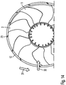
- FIG. 1 shows a front perspective view of an exemplary radiator fan module 1.
- the view in Fig. 1 represents the side of the radiator fan module 1, from which the radiator fan module 1 draws air.
- the exemplary radiator fan module 1 has a frame 3, which in this example has a substantially rectangular shape. Within the frame 3, a recess is provided, in which a fan 2 is arranged. The fan 2 (not shown) via mounting struts attached to the frame 3. Between the fan 2 and the frame 3, a remindstromleit Vietnamese 4 is arranged. The remindstromleit Vietnamese 4 directs a return flow, which arises due to the suction side negative pressure, again the same, so that conditionally the return flow is no longer swirling. The return flow is mixed as a rectified flow again with the main flow, which flows centrally through the impeller 2, and applies rectified to the fan blades 11 of the impeller 2.
- the frame 3 is formed for example of a plastic.
- the frame 3 and the remindstromleit driving 4 are formed as separate parts.
- Fig. 2 shows a rear perspective view of the exemplary radiator fan module 1 from Fig. 1 , This rear view represents the side of the radiator fan module 1 from which the cooling air flows out of the radiator fan module 1.
- the remindstromleit Vietnamese 4 is disposed between the fan 2 and the frame 3.
- the scaffoldstromleit Hughes 4 is formed as a return ring, which extends around the circumference of the fan wheel 2.
- the return flow ring has an inner ring 5 and an outer ring 6. Between the inner ring 5 and the outer ring 6, an air gap 7 is provided, through which flows the return flow of the radiator fan module.
- the inner ring 5 is connected to the outer ring 6 via Heilleitrippen 8.
- These air guide ribs 8 extend around the circumference of the return flow ring 4 and are aligned substantially in the radial direction.
- the Dunleitrippen 8 may be elastic, for example made of an elastic plastic.
- the remindstromleit noise 4 also has a profile 9, which redirects the return flow so that they again mixed well with the main flow.
- the profile 9 may be provided both on the inner ring 5 and on the outer ring 6.
- the fan 2 of the radiator fan module 1 has in this example a fan outer ring 12 and a fan hub 10, wherein the hub 10 with the fan outer ring 12 via the Lüfterradschaufeln 11 is connected. In the middle of the hub 10, a motor is arranged, which drives the fan 2.
- Other embodiments of fan wheels 2 are of course also possible.
- FIG. 3 shows an exemplary remindstromleit Nur 4 in various representations.
- the two illustrations on the left side of the FIG. 3 Man recognizes that the inner ring 5 of the remindstromleit Vietnamese 4 extends substantially in the axial direction and the outer ring 6 is substantially in the radial direction. Furthermore, it can be seen that the air guide ribs 8 are conical to the axis of the fan wheel 2. This arrangement of the Gutleitrippen 8 increases the area in which the return flow comes into contact with the Heilleitrippen 8.
- the two upper right representations of the remindstromleit immunity 4 in FIG. 3 show the grillstromleit prepared 4 in perspective views respectively from the front and from behind.
- the two lower illustrations on the right in FIG. 3 each show detailed views of the remindstromleit disturbed 4th
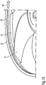
- FIG. 4 shows a flow pattern of the exemplary radiator fan module 1 from the rear.
- the flow pattern represents the air flow in the region of the return flow guide device 4.
- the arrows 13, 14 represent the direction of the air flow at the return flow guide device 4. It can be seen that through the air gap 7 of the return flow guide device 4 a flow from the rear side of the radiator fan module 1 to the front side the cooling fan module 1 is sucked. This return flow 13 is caused by the prevailing at the front of the radiator fan module 1 negative pressure. This return flow 13 is not twisty.
- the return flow 13 is rectified in the passage through the air gap 7 through the Heilleitrippen 8 and 9 through the profile, mixes with the highly swirling fan wheel gap flow and is now sucked swirl reduced with the main flow on the front of the radiator fan module 1 again.
- the main flow has less turbulence, which leads to an improved onflow behavior of the radiator fan module and to a concomitant reduced noise development of the radiator fan module 1.
- FIG. 5 shows a flow pattern of the exemplary radiator fan module 1 from the front. It can be seen that the return flow 13 is no longer twisty after a passage through the remindstromleit Anlagen 4 and mixes well with the fan wheel gap flow and the main flow 14 of the radiator fan module 1.
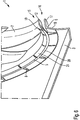
- Fig. 6 shows a perspective sectional view of an embodiment of a radiator fan module 1.
- the fan outer ring 12 between the inner ring 5 of the remindstromleit Vietnamese 4 and the outer ring 6 of the remindstromleit Vietnamese 4 is arranged.
- the outer ring 6 has an outer ring portion 17, which extends in the axial direction.
- the outer ring 6 of the remindstromleit Hughes 4 on an outer ring portion 18, which extends in a radial direction substantially.
- the inner ring 5 of the remindstromleit Vietnamese 4 also has a Inner ring portion 19 which extends in the axial direction of the radiator fan module 1 and an inner ring portion 20 which extends in a substantially radial direction. Between the inner ring portion 19 and the inner ring portion 20, a transition 21 may be formed in the shape of a bow.
- the Luftleitrippen 8 which are provided between the inner ring 5 and the outer ring 6 of the remindstromleit Road 4, extend in this embodiment of the radiator fan module 1 substantially in the radial direction.
- the outer air gap 16, in this embodiment the impeller gap, is configured to direct a return flow from the radiator fan module pressure side to the radiator fan module suction side in substantially a same direction.
- the radiator fan module 1 is thedeerlrangeermodultikseite on the right side and thedeervolermodulansaugseite on the left side.
- the inner air gap 15 is designed to generate a flow which has substantially the same direction as the main air flow of the fan wheel 2, ie in the in Fig. 6 shown example from left to right.
- the inner air gap 15 is configured such that it extracts swirl-free air from the radiator fan module on the intake side and supplies it to the impeller gap flow of the radiator fan module 1.
- the air flows radially into the remindstromleit Vietnamese 4, is guided by the Heilleitrippen 8, then mixes with the impeller gap current flowing in the outer air gap 16, and then flows in the direction of the impeller 2.
- the impeller gap flow (backflow), which occurs in the outer air gap 16 is withdrawn by the flow in the inner air gap 15 by the mixing swirl. In this way, the performance of the radiator fan module is increased. Furthermore, it comes in this way to a reduction in the noise of the radiator fan module 1. Furthermore, thereby the efficiency of the radiator fan module 1 can be further increased.
- the Heilleitrippen 8 can also extend obliquely or bent.
- the air guide ribs 8 and / or the transition 21 are formed elastically such that the inner ring 5 is movable relative to the outer ring 6 so that the fan 2 can be pushed through the remindstromleit Vietnamese 4.
- the entire inner ring 5 may be formed of an elastic material.
- the remindstromleit prepared 4 is formed as a separate component, and not integrally formed with the frame 3.
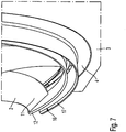
- Fig. 7 is a rear perspective view of a section of the radiator fan module 1 of Fig. 6 , In this view, it can be seen that the outer ring portion 17 extends substantially in the axial direction of the radiator fan module 1. In the outer air gap 16, a backflow flows from the back to the front of the radiator fan module 1. The main flow of the radiator fan module 1 extends in the radiator fan module 1 of Fig. 7 from right to left, whereas the return flow (impeller gap flow) 16 runs from left to right.
- FIG. 16 is a front perspective view of the radiator fan module 1 of FIG Fig. 6 ,
- the motor 10, which is arranged in the hub of the fan wheel 2 and drives the fan wheel 2, is connected to the frame 3 by means of fastening struts (not shown). If the air guide ribs 8 and / or the transition 21 are elastic, it is possible to mount the fan wheel 2 together with the motor 10 through the return flow guide device 4 to be mounted on the fastening struts. In the example shown, the fan wheel 2 would be inserted from left to right through the remindstromleit Nur 4, wherein the Heilleitrippen 8 and / or the transition 21 elastically deform during the passage of the fan wheel 2, and assume their original shape after insertion. In this way, the radiator fan module 1 can be manufactured and mounted in a particularly simple manner.
- Fig. 9 is another perspective rear view of the radiator fan module 1 of Fig. 6 .
- mounting brackets (not shown) are provided on the frame, which connect the fan 2 together with the motor 10 with the frame 3.
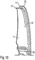
- Fig. 10 shows an exemplary fan 2.
- the fan 2 has a plurality of fan blades 11, which extend from a hub 25 to the outside, ie in the radial direction.
- the fan blades 11 are connected to each other by means of a fan outer ring 12.
- the fan outer ring 12 has a fan outer ring portion 111 which extends in the radial direction, whereas the fan outer ring 12 extends in the axial direction.
- a second fan outer ring 22 is provided, which is connected via a plurality ofthinkringluftleitrippen 23 with the fan outer ring portion 111.
- the outer ring air guide ribs 23 are formed to generate a flow of air in the radial direction between the fan outer ring portion 111 and the second fan outer ring 22 from outside to inside or from inside to outside.
- the intuitionringluftleitrippen 23 are arranged in a suitable angle.
- the fan-wheel air-guiding ribs 23 can be arranged at an angle such that an air flow in the radial direction results from the outside inwards or from the inside outwards. In this way, the efficiency of the radiator fan module 1 can be further increased, since in this way results in an optimized flow profile.
- the swirling fan gap flow is removed in this way from the fan gap and thereby no longer contributes to the swirling of the intake flow. In this way, the noise of the radiator fan module 1 is further reduced.
- This in Fig. 11 illustrated exemplary fan 2 may be formed, for example, as a one-piece injection molded part. Furthermore, it is also possible to form the second fan wheel outer ring 22 together with the outer ring air guide ribs 23 as a separate part, which can be connected to a conventional fan wheel 2. For example, the second fan wheel outer ring 22 can be connected to the fan wheel 2 by means of gluing and / or friction welding.
- Fig. 12 shows a further illustration of the exemplary fan wheel 2 in a perspective side view.
- Fig. 13 shows a top perspective view of the exemplary fan 2 of Fig. 10 ,
- the fan 2 which in Fig. 13 For example, as shown by arrow 30, it rotates clockwise as viewed to the right.
- the intuitionringluftleitrippen 23 are provided such that there is a flow between the fan outer ring 12 and the second fan outer ring 22, which flows from the inside to the outside.
- Fig. 14 is a sectional perspective view of the exemplary fan 2 of the Fig. 10 , The cut runs through the outer ring air guide ribs 23 and the Lüfterradschaufeln 11. The cut surfaces are shown dark. If the fan 2 rotates to the left, as indicated by the arrow 31, results in an air flow, which flows from outside to inside, as indicated by the arrow 32.
- the outer ring air guiding ribs 23 may also be provided in a curved shape.
Landscapes
- Engineering & Computer Science (AREA)
- Mechanical Engineering (AREA)
- General Engineering & Computer Science (AREA)
- Chemical & Material Sciences (AREA)
- Combustion & Propulsion (AREA)
- Structures Of Non-Positive Displacement Pumps (AREA)
Description
- Die vorliegende Erfindung betrifft ein Kühlerlüftermodul.
- Kühlerlüftermodule werden zum Kühlen des Motors in Kraftfahrzeugen eingesetzt. Bei Kühlerlüftermodulen ist man im Allgemeinen bestrebt, das Kühlerlüftermodul so kostengünstig wie möglich herzustellen. Ein weiterer Aspekt stellt der Komfort der Fahrzeuginsassen dar, insbesondere was die Minimierung der Geräuschentwicklung des Kühlerlüftermoduls angeht.
- Ein Kühlerlüftermodul besteht typischerweise aus einem Lüfterrad, in welchen ein Motor zum Antrieb des Lüfterrades angeordnet ist, und einer Zarge, welche Montagestreben zur Befestigung des Lüfterrades aufweist. Das Lüfterrad eines Kühlerlüftermoduls ist dazu ausgelegt, eine Luftströmung zu erzeugen, mit der vom Motor erzeugte Wärme abgetragen werden soll. Bei heute verwendeten Kühlerlüftermodulen existiert neben der Hauptströmung eine so genannte Spaltströmung. Die Spaltströmung bezeichnet die Strömung, welche sich zwischen dem Lüfterrad und der Zarge aufgrund des Unterdruckes ausbildet und welche wegen der Rotation des Lüfterrades drallbehaftet ist. Die drallbehaftete Spaltströmung wirkt der Hauptströmung entgegen, wodurch das Anströmverhalten des Kühlerlüftermoduls negativ beeinflusst wird. Diese Fehlanströmung führt mitunter zu einer sehr hohen Geräuschentwicklung, was den Komfort der Passagiere beim Betrieb des Kraftfahrzeuges mindert.
- Die
DE 10 2008 046 508 A1 beschreibt eine Lüftervorrichtung zur Belüftung eines Verbrennungsmotors für ein Kraftfahrzeug mit zumindest einem Lüfterrad mit Lüfterradblättern zur Luftansaugung, die zumindest einen Lüfterradmantel mit einer Lüfterradnabe verbinden, mit zumindest einer Lüfterzarge, in der zumindest ein Lüfterrad angeordnet ist, wobei zwischen zumindest einem Lüfterradmantelabschnitt und einem Lüfterzargenabschnitt ein erster Spalt derart ausgebildet ist, dass er zumindest abschnittsweise radial bezüglich einer Hauptluftstromrichtung und in Richtung der bei einer Drehbewegung des Lüfterrades auftretenden Zentrifugalkraft verläuft zur Minimierung zumindest eines Luftstroms. - Die
DE 10 2007 036 304 A1 beschreibt Vorrichtung zur Kühlung eines Motors, umfassend einen luftdurchströmbaren Wärmetauscher, einen im Bereich des Wärmetauschers angeordneten Lüfter mit einer Lüfterachse und eine an dem Wärmetauscher angeordnete Lüfterhaube, wobei die Lüfterhaube einen Strömungsraum zwischen dem Lüfter und dem Wärmetauscher umgibt und von einem Außenraum begrenzt, wobei mittels der Lüfterhaube ein luftdurchströmbarer Spalt im Bereich eines radial äußeren Umfangs des Lüfters vorgesehen ist, durch den eine Spaltströmung von dem Strömungsraum in den Außenraum strömen kann, wobei die Spaltströmung in einer von der Lüfterachse radial abweichenden Richtung in den Außenraum strömt. - Die
WO 2008/124656 A1 beschreibt einen Ringlüfter mit einem Lüfterrad und einer Zarge. Die Zarge weist eine ringförmige Rückstromleiteinrichtung auf. - Die
WO 98/37319 A1 - Die
FR 2 816 360 A1 - Die
EP 2 236 788 A1 beschreibt eine Kühlvorrichtung für ein Kraftfahrzeug. Die Kühlvorrichtung weist einen Axiallüfter mit einem umlaufenden Mantelring auf. Im Mantelring ist ein ortsfest angeordneter Leitring zugeordnet. - Die
WO 93/05275 A1 GB 2 358 677 A - Die
EP 1 830 072 A2 beschreibt eine Lüfterzarge für einen Wärmeübertrager mit einem Zargenring zur Aufnahme eines Axiallüfters, wobei dem Axiallüfter in Luftströmungsrichtung gesehen mindestens ein Strömungsleitelement vorgeschaltet ist. - Vor diesem Hintergrund ist es eine Aufgabe der vorliegenden Erfindung, ein verbessertes Kühlerlüftermodul für ein Kraftfahrzeug bereit zu stellen.
- Erfindungsgemäß wird diese Aufgabe durch ein Kühlerlüftermodul mit den Merkmalen des Patentanspruchs 1 gelöst.
- Die der Erfindung zugrunde liegende Idee besteht darin, mittels einer eigens dazu vorgesehenen Rückstromleiteinrichtung die drallbehafte Rückströmung in eine Vorzugsrichtung zu leiten und zu entdrallen. Die Rückstromleiteinrichtung richtet die Rückströmung wieder gleich, so dass diese nicht mehr drallbehaftet ist, und mischt diese Rückströmung mit der Strömung, welche zwischen dem Innenring der Rückstromleiteinrichtung und dem Lüfterrad-Außenring strömt. Die Strömung der Hauptströmung bleibt damit, auch nach der Vermischung der mit der Rückströmung vermischten Strömung durch die Rückstromleiteinrichtung, drallfrei, sodass eine drallfreie Strömung auf die Lüfterschaufeln trifft. Dadurch wird die Geräuschabstrahlung des Kühlerlüftermoduls reduziert. Ferner ergibt sich dadurch ein besseres Anströmverhalten des Kühlerlüftermoduls, was die Effektivität des Kühlerlüftermoduls steigert.
- In einer typischen Ausgestaltung ist die Rückstromleiteinrichtung zwischen der Zarge und dem Lüfterrad angeordnet. Der Lüfterradaußenring ist erfindungsgemäß zwischen dem Innenring und dem Außenring der Leiteinrichtung angeordnet.
- Vorteilhafte Ausgestaltungen und Weiterbildungen ergeben sich aus den weiteren Unteransprüchen sowie aus der Beschreibung unter Bezugnahme auf die Figuren der Zeichnung.
- Die Rückstromleiteinrichtung weist eine Vielzahl von Luftleitrippen auf, welche zwischen dem Innenring und dem Außenring vorgesehen sind, und welche sich z. B. in Radialrichtung vom Innenring zum Außenring erstrecken. Durch diese Luftleitrippen kann die drallbehaftete Rückströmung noch besser gleichgerichtet werden, was zu einem noch besseren Anströmverhalten des Kühlerlüftermoduls führt.
- In einer weiteren bevorzugten Ausführungsform sind die Luftleitrippen und/oder der Übergang derart elastisch ausgebildet, dass das Lüfterrad durch die Leiteinrichtung hindurchsteckbar ist. Auf diese Weise kann das Kühlerlüfermodul auf sehr einfache Art montiert werden.
- In einer weiteren bevorzugten Ausführungsform ist der gesamte Innenring derart elastisch ausgebildet, dass das Lüfterrad durch die Leiteinrichtung hindurchsteckbar ist.
- In einer weiteren bevorzugten Ausführungsform ist die Zarge aus einem duroplastischen Kunststoff ausgebildet, und die Leiteinrichtung mit dem elastischen Übergang und/oder den elastischen Luftleitrippen ist aus einem thermoplastischen oder elastomeren Kunststoff ausgebildet. In einer weiteren bevorzugten Ausführungsform können nur die Luftleitrippen oder nur der Übergang aus einem thermoplastischen oder elastomeren Kunststoff ausgebildet sein.
- In einer weiteren bevorzugten Ausführungsform ist die Zarge als ein Kunststoffspritzgussteil ausgebildet. Auf diese Weise kann das Kühlerlüftermodul besonders kostengünstig hergestellt werden. Als Kunststoffe für die Zarge und die Rückstromleiteinrichtung eignen sich beispielsweise thermoplastische, duroplastische und/oder elastomere Kunststoffe. Jedoch können die Zarge und die Rückstromleiteinrichtung auch aus anderen Materialien, wie z. B. einem metallischen Werkstoff, und durch einen anderes Fertigungsverfahren, z. B. Fräsen, hergestellt werden.
- Es ist ein Motor vorgesehen, welcher das Lüfterrad antreibt. Der Motor kann beispielsweise als ein bürstenloser Gleichstrommotor ausgebildet sein, welcher in der Nabe des Lüfterrades angeordnet ist. Jedoch sind auch andere Bauweisen von Motoren bei dem erfindungsgemäßen Kühlerlüftermodul verwendbar.
- In einer weiteren bevorzugten Ausführungsform ist das Kühlerlüftermodul als vorzugsweise als Axial-Lüfter ausgebildet. Er wäre allerdings auch denkbar und vorteilhaft, wenn das Kühlerlüftermodul als Diagonal-Lüfter oder Radial-Lüfter ausgebildet ist. Zudem können auch andere Bauweisen von Kühlerlüftermodulen mit einer Rückstromleiteinrichtung versehen werden.
- Die obigen Ausgestaltungen und Weiterbildungen lassen sich, sofern sinnvoll, beliebig miteinander kombinieren. Weitere mögliche Ausgestaltungen, Weiterbildungen und Implementierungen der Erfindung umfassen auch nicht explizit genannte Kombinationen von zuvor oder im Folgenden bezüglich der Ausführungsbeispiele beschriebenen Merkmale der Erfindung. Insbesondere wird dabei der Fachmann auch Einzelaspekte als Verbesserungen oder Ergänzungen zu der jeweiligen Grundform der vorliegenden Erfindung hinzufügen.
- Die vorliegende Erfindung wird nachfolgend anhand der in den schematischen Figuren der Zeichnungen angegebenen Ausführungsbeispiele näher erläutert. Es zeigen dabei:
- Fig. 1
- eine perspektivische Vorderansicht eines beispielhaften Kühlerlüftermoduls;
- Fig. 2
- eine perspektivische Rückansicht des beispielhaften Kühlerlüftermoduls aus
Fig. 1 ; - Fig. 3
- verschiedene Ansichten einer beispielhaften Rückstromleiteinrichtung;
- Fig. 4
- ein Strömungsbild des beispielhaften Kühlerlüftermoduls von hinten;
- Fig. 5
- ein Strömungsbild des beispielhaften Kühlerlüftermoduls von vorne.
- Fig. 6
- eine perspektivische Schnittansicht einer Ausführungsform eines Kühlerlüftermoduls;
- Fig. 7
- eine perspektivische Rückansicht eines Ausschnitts des Kühlerlüftermoduls der
Fig. 6 ; - Fig. 8
- eine perspektivische Vorderansicht des Kühlerlüftermoduls der
Fig. 6 ; - Fig. 9
- eine perspektivische Rückansicht des Kühlerlüftermoduls der
Fig. 6 ; - Fig. 10
- eine Schnittansicht eines beispielhaften Lüfterrades;
- Fig. 11
- eine perspektivische Vorderansicht des beispielhaften Lüfterrades gemäß
Fig. 10 ; - Fig. 12
- eine perspektivische Seitenansicht des beispielhaften Lüfterrades der
Fig. 10 ; - Fig. 13
- eine perspektivische Draufsicht des beispielhaften Lüfterrades der
Fig. 10 ; und - Fig. 14
- eine perspektivische Schnittansicht des beispielhaften Lüfterrades der
Fig. 10 . - Die beiliegenden Zeichnungen sollen ein weiteres Verständnis der Ausführungsformen der Erfindung vermitteln. Sie veranschaulichen Ausführungsformen und dienen im Zusammenhang mit der Beschreibung der Erklärung von Prinzipien und Konzepten der Erfindung. Andere Ausführungsformen und viele der genannten Vorteile ergeben sich im Hinblick auf die Zeichnungen. Die Elemente der Zeichnungen sind nicht notwendigerweise maßstabsgetreu zueinander gezeigt.
- In den Figuren der Zeichnung sind gleiche, funktionsgleiche und gleich wirkende Elemente, Merkmale und Komponenten - sofern nichts Anderes ausführt ist - jeweils mit desselben Bezugszeichen versehen.
-
Figur 1 zeigt eine perspektivische Vorderansicht eines beispielhaften Kühlerlüftermoduls 1. Die Ansicht inFig. 1 stellt die Seite des Kühlerlüftermoduls 1 dar, von welcher aus das Kühlerlüftermodul 1 Luft ansaugt. - Das beispielhafte Kühlerlüftermodul 1 weist eine Zarge 3 auf, welche in diesem Beispiel eine im Wesentlichen rechteckige Form aufweist. Innerhalb der Zarge 3 ist eine Aussparung vorgesehen, in welcher ein Lüfterrad 2 angeordnet ist. Das Lüfterrad 2 ist über Montagestreben (nicht dargestellt) an der Zarge 3 befestigt. Zwischen dem Lüfterrad 2 und der Zarge 3 ist eine Rückstromleiteinrichtung 4 angeordnet. Die Rückstromleiteinrichtung 4 richtet eine Rückströmung, welche aufgrund des ansaugseitigen Unterdrucks entsteht, wieder gleich, so dass dadurch bedingt die Rückströmung nicht mehr drallbehaftet ist. Die Rückströmung wird als gleichgerichtete Strömung wieder mit der Hauptströmung, welche zentral durch das Lüfterrad 2 strömt, vermischt und trifft gleichgerichtet auf die Lüfterradschaufeln 11 des Lüfterrades 2 auf.
- Die Zarge 3 ist beispielsweise aus einem Kunststoff ausgebildet. Die Zarge 3 und die Rückstromleiteinrichtung 4 sind als separate Teile ausgebildet.
-
Fig. 2 zeigt eine perspektivische Rückansicht des beispielhaften Kühlerlüftermoduls 1 ausFig. 1 . Diese Rückansicht stellt die Seite des Kühlerlüftermoduls 1 dar, von welcher die Kühlluft aus dem Kühlerlüftermodul 1 herausströmt. - Die Rückstromleiteinrichtung 4 ist zwischen dem Lüfterrad 2 und der Zarge 3 angeordnet. In diesem Beispiel ist die Rückstromleiteinrichtung 4 als ein Rückstromring ausgebildet, welcher sich um den Umfang des Lüfterrades 2 erstreckt. Der Rückstromring weist einen Innenring 5 und einen Außenring 6 auf. Zwischen dem Innenring 5 und dem Außenring 6 ist ein Luftspalt 7 vorgesehen, durch welchen die Rückströmung des Kühlerlüftermoduls strömt. Der Innenring 5 ist mit dem Außenring 6 über Luftleitrippen 8 verbunden. Diese Luftleitrippen 8 erstrecken sich um den Umfang des Rückstromringes 4 und sind im Wesentlichen in Radial-Richtung ausgerichtet. Jedoch wäre auch eine andere Anordnung der Luftleitrippen 8, z. B. eine schräge Ausrichtung, möglich. Die Luftleitrippen 8 können elastisch ausgebildet sein, beispielsweise aus einem elastischen Kunststoff. Die Rückstromleiteinrichtung 4 weist ferner ein Profil 9 auf, welches die Rückströmung derart umleitet, sodass sich diese wieder gut mit der Hauptströmung vermischt. Das Profil 9 kann sowohl am Innring 5 als auch am Außenring 6 vorgesehen sein.
- Das Lüfterrad 2 des Kühlerlüftermoduls 1 weist in diesem Beispiel einen Lüfterrad-Außenring 12 und eine Lüfterrad-Nabe 10 auf, wobei die Nabe 10 mit dem Lüfterrad-Außenring 12 über die Lüfterradschaufeln 11 verbunden ist. In der Mitte der Nabe 10 ist ein Motor angeordnet, welcher das Lüfterrad 2 antreibt. Andere Ausgestaltungen von Lüfterrädern 2 sind natürlich auch möglich.
-
Figur 3 zeigt eine beispielhafte Rückstromleiteinrichtung 4 in verschiedenen Darstellungen. Die zwei Darstellungen auf der linken Seite derFigur 3 stellen die Rückstromleiteinrichtung 4 in einer Vorderansicht und in einer Draufsicht dar. Mann erkennt, dass der Innenring 5 der Rückstromleiteinrichtung 4 sich in Wesentlichen in Axialrichtung und der Außenring 6 sich im Wesentlichen in Radial-Richtung erstreckt. Ferner ist zu erkennen, dass die Luftleitrippen 8 konisch zur Achse des Lüfterrades 2 fluchtend sind. Diese Anordnung der Luftleitrippen 8 vergrößert den Bereich, in welchen die Rückströmung mit den Luftleitrippen 8 in Kontakt kommt. Die zwei oberen rechten Darstellungen der Rückstromleiteinrichtung 4 inFigur 3 zeigen die Rückstromleiteinrichtung 4 in perspektivischen Ansichten jeweils von Vorne und von Hinten. Die zwei unteren Darstellungen auf der rechten Seite inFigur 3 zeigen jeweils Detailansichten der Rückstromleiteinrichtung 4. -
Figur 4 zeigt ein Strömungsbild des beispielhaften Kühlerlüftermoduls 1 von hinten. Das Strömungsbild stellt die Luftströmung im Bereich der Rückstromleiteinrichtung 4 dar. Die Pfeile 13, 14 stellen die Richtung der Luftströmung an der Rückstromleiteinrichtung 4 dar. Man erkennt, dass durch den Luftspalt 7 der Rückstromleiteinrichtung 4 eine Strömung von der Rückseite des Kühlerlüftermoduls 1 zu der Vorderseite des Kühlerlüftermoduls 1 gesaugt wird. Diese Rückströmung 13 wird durch den an der Vorderseite des Kühlerlüftermoduls 1 herrschenden Unterdruck verursacht. Diese Rückströmung 13 ist nicht drallbehaftet. Die Rückströmung 13 wird bei dem Durchgang durch den Luftspalt 7 durch die Luftleitrippen 8 und durch das Profil 9 gleichgerichtet, mischt sich mit der stark drallbehafteten Lüfterrad-Spaltströmung und wird nun drallreduziert mit der Hauptströmung auf der Vorderseite des Kühlerlüftermoduls 1 wieder angesaugt. Dadurch weist die Hauptströmung weniger Turbulenzen auf, was zu einem verbesserten Anströmverhalten des Kühlerlüftermoduls und zu einer damit einhergehenden verminderten Geräuschentwicklung des Kühlerlüftermoduls 1 führt. -
Figur 5 zeigt ein Strömungsbild des beispielhaften Kühlerlüftermoduls 1 von vorne. Man erkennt, dass die Rückströmung 13 nach einem Durchgang durch die Rückstromleiteinrichtung 4 nicht mehr drallbehaftet ist und sich gut mit der Lüfterrad-Spaltströmung und der Hauptströmung 14 des Kühlerlüftermoduls 1 vermischt. -
Fig. 6 zeigt eine perspektivische Schnittansicht einer Ausführungsform eines Kühlerlüftermoduls 1. In dieser Ausführungsform des Kühlerlüftermoduls 1 ist der Lüfterrad-Außenring 12 zwischen dem Innenring 5 der Rückstromleiteinrichtung 4 und dem Außenring 6 der Rückstromleiteinrichtung 4 angeordnet. Dadurch ergibt sich ein äußerer Luftspalt 16 zwischen dem Lüfterrad-Außenring 12 und dem Außenring 6 der Rückstromleiteinrichtung 4 und ein innerer Luftspalt 15 zwischen dem Lüfterrad-Außenring 12 und dem Innenring 5 der Rückstromleiteinrichtung 4. Der Außenring 6 weist einen Außenringabschnitt 17 auf, welcher sich in axialer Richtung erstreckt. Ferner weist der Außenring 6 der Rückstromleiteinrichtung 4 einen Außenringabschnitt 18 auf, welcher sich im Wesentlichen in eine radiale Richtung erstreckt. Der Innenring 5 der Rückstromleiteinrichtung 4 weist ebenfalls einen Innenringabschnitt 19 auf, welcher sich in axialer Richtung des Kühlerlüftermoduls 1 erstreckt und einen Innenringabschnitt 20 auf, welcher sich im Wesentlichen in einer radialen Richtung erstreckt. Zwischen dem Innenringabschnitt 19 und dem Innenringabschnitt 20 kann ein Übergang 21 in der Form eines Bogens ausgebildet sein. - Auch zwischen dem Außenringabschnitt 17 und dem Außenringabschnitt 18 kann ein Übergang in der Form einer Rundung vorgesehen sein. Die Luftleitrippen 8, welche zwischen dem Innenring 5 und dem Außenring 6 der Rückstromleiteinrichtung 4 vorgesehen sind, erstrecken sich in dieser Ausführungsform des Kühlerlüftermoduls 1 im Wesentlichen in radialer Richtung.
- Der äußere Luftspalt 16, in dieser Ausführungsform der Laufradspalt, ist ausgebildet, um eine Rückströmung von der Kühlerlüftermoduldruckseite auf die Kühlerlüftermodulsaugseite im Wesentlichen in eine gleiche Richtung zu leiten. In dem in
Fig. 6 dargestellten Ausführungsbeispiel des Kühlerlüftermoduls 1 ist die Kühlerlüftermoduldruckseite auf der rechten Seite und die Kühlerlüftermodulansaugseite auf der linken Seite. - Der innere Luftspalt 15 ist ausgebildet, um eine Strömung zu erzeugen, welche im Wesentlichen die gleiche Richtung wie die Hauptluftströmung des Lüfterrades 2 aufweist, also in dem in
Fig. 6 gezeigten Beispiel von links nach rechts. Der innere Luftspalt 15 ist mit anderen Worten derart ausgestaltet, dass er Kühlerlüftermodul-saugseitig drallfreie Luft entnimmt und dem Laufradspaltstrom des Kühlerlüftermoduls 1 zuführt. Die Luft strömt radial in die Rückstromleiteinrichtung 4 ein, wird durch die Luftleitrippen 8 geführt, vermischt sich dann mit dem Laufradspaltstrom, welcher in dem äußeren Luftspalt 16 strömt, und strömt dann in Richtung des Lüfterrades 2. Dem Laufradspaltstrom (Rückströmung), welcher in dem äußeren Luftspalt 16 auftritt, wird durch die Strömung im inneren Luftspalt 15 durch die Vermischung Drall entzogen. Auf diese Weise wird die Leistung des Kühlerlüftermoduls gesteigert. Ferner kommt es auf diese Weise zu einer Verminderung der Geräuschentwicklung des Kühlerlüftermoduls 1. Ferner kann dadurch der Wirkungsgrad des Kühlerlüftermoduls 1 weiter gesteigert werden. Die Luftleitrippen 8 können auch sich schräg oder gebogen erstrecken. - Gemäß einer vorteilhaften Ausgestaltung sind die Luftleitrippen 8 und/oder der Übergang 21 derart elastisch ausgebildet, dass der Innenring 5 bezüglich des Außenrings 6 derart bewegbar ist, dass das Lüfterrad 2 durch die Rückstromleiteinrichtung 4 hindurchsteckbar ist. Ferner kann auch der gesamte Innenring 5 aus einem elastischen Material ausgebildet sein. Eine derartig ausgebildete Rückstromleiteinrichtung 4 kann beispielsweise in einem Zweikomponentenspritzguß hergestellt werden.
- Die Rückstromleiteinrichtung 4 ist als separates Bauteil ausgebildet, und nicht einstückig mit der Zarge 3 ausgebildet.
-
Fig. 7 ist eine perspektivische Rückansicht eines Ausschnitts des Kühlerlüftermoduls 1 derFig. 6 . In dieser Ansicht erkennt man, dass der Außenringabschnitt 17 sich im Wesentlichen in axialer Richtung des Kühlerlüftermoduls 1 erstreckt. In dem äußeren Luftspalt 16 strömt eine Rückströmung von der Rückseite zu der Vorderseite des Kühlerlüftermoduls 1. Die Hauptströmung des Kühlerlüftermoduls 1 verläuft bei dem Kühlerlüftermodul 1 derFig. 7 von rechts nach links, wohingegen die Rückströmung (Laufradspaltströmung) 16 von links nach rechts verläuft. -
Fig. 8 ist eine perspektivische Vorderansicht des Kühlerlüftermoduls 1 derFig. 6 . Der Motor 10, welcher in der Nabe des Lüfterrades 2 angeordnet ist und das Lüfterrad 2 antreibt, ist mittels Befestigungsstreben (nicht dargestellt) mit der Zarge 3 verbunden. Falls die Luftleitrippen 8 und/oder der Übergang 21 elastisch ausgebildet sind, ist es möglich, das Lüfterrad 2 samt Motor 10 durch die Rückstromleiteinrichtung 4 hindurchzustecken an den Befestigungsstreben zu montieren. In dem dargestellten Beispiel würde das Lüfterrad 2 von links nach rechts durch die Rückstromleiteinrichtung 4 hindurchgesteckt, wobei sich die Luftleitrippen 8 und/oder der Übergang 21 beim Durchgang des Lüfterrades 2 elastisch verformen, und nach dem Durchstecken ihre ursprüngliche Form wieder annehmen. Auf diese Weise kann das Kühlerlüftermodul 1 auf besonders einfache Weise hergestellt und montiert werden. -
Fig. 9 ist eine weitere perspektivische Rückansicht des Kühlerlüftermoduls 1 derFig. 6 . Auf der Rückseite des Kühlerlüftermoduls 1 sind an der Zarge 3 Befestigungsstreben (nicht dargestellt) vorgesehen, welche das Lüfterrad 2 samt Motor 10 mit der Zarge 3 verbinden. -
Fig. 10 zeigt ein beispielhaftes Lüfterrad 2. Das Lüfterrad 2 weist eine Vielzahl von Lüfterradschaufeln 11 auf, welche sich von einer Nabe 25 nach außen, also in radialer Richtung, erstrecken. An der äußeren Umfangslinie des Lüfterrades 2 sind die Lüfterradschaufeln 11 mittels eines Lüfterrad-Außenrings 12 miteinander verbunden. Der Lüfterrad-Außenring 12 weist einen Lüfterrad-Außenringabschnitt 111 auf, welcher sich in radialer Richtung erstreckt, wohingegen der Lüfterrad-Außenring 12 sich in axialer Richtung erstreckt. Parallel zu dem Lüfterrad-Außenringabschnitt 111 ist ein zweiter Lüfterrad-Außenring 22 vorgesehen, welcher über eine Vielzahl von Außenringluftleitrippen 23 mit dem Lüfterrad-Außenringabschnitt 111 verbunden ist. Die Außenringluftleitrippen 23 sind ausgebildet, um eine Luftströmung in radialer Richtung zwischen dem Lüfterrad-Außenringabschnitt 111 und dem zweiten Lüfterrad-Außenring 22 von außen nach innen oder von innen nach außen zu erzeugen. Hierfür sind die Außenringluftleitrippen 23 in einem hierfür geeigneten Winkel angeordnet. - Je nach Bedarf und Anwendungsumgebung können die Lüfterradluftleitrippen 23 derart in einem Winkel angeordnet sein, dass sich eine Luftströmung in radialer Richtung von außen nach innen oder von innen nach außen ergibt. Auf diese Weise kann der Wirkungsgrad des Kühlerlüftermoduls 1 weiter erhöht werden, da sich auf diese Weise ein optimiertes Strömungsprofil ergibt. Die drallbehaftete Lüfterspaltströmung wird auf diese Weise aus dem Lüfterspalt entzogen und trägt dabei nicht mehr zur Verwirbelung der Ansaugströmung bei. Auf diese Art wird die Geräuschentwicklung des Kühlerlüftermoduls 1 weiter reduziert.
- Das in
Fig. 11 dargestellte beispielhafte Lüfterrad 2 kann beispielsweise als ein einstückiges Spritzgussteil ausgebildet sein. Ferner ist es auch möglich, den zweiten Lüfterrad-Außenring 22 samt den Außenringluftleitrippen 23 als separates Teil auszubilden, welches mit einem herkömmlichen Lüfterrad 2 verbunden werden kann. Beispielsweise kann der zweite Lüfterrad-Außenring 22 mittels Kleben und/oder Reibschweißen mit dem Lüfterrad 2 verbunden werden. -
Fig. 12 zeigt eine weitere Darstellung des beispielhaften Lüfterrades 2 in einer perspektivischen Seitenansicht. -
Fig. 13 zeigt eine perspektivische Draufsicht des beispielhaften Lüfterrades 2 derFig. 10 . Das Lüfterrad 2, welches inFig. 13 dargestellt ist, dreht sich beispielsweise rechts herum, wie durch den Pfeil 30 veranschaulicht. Die Außenringluftleitrippen 23 sind dabei derart vorgesehen, dass sich eine Strömung zwischen dem Lüfterrad-Außenring 12 und dem zweiten Lüfterrad-Außenring 22 ergibt, welche von innen nach außen strömt. - Falls die Drehrichtung des Lüfterrades 2 entgegengesetzt ist, also entgegen der Richtung, welche durch den Pfeil 30 veranschaulicht wird, würde sich eine Strömung zwischen dem Lüfterrad-Außenring 12 und dem zweiten Lüfterrad-Außenring 22 ergeben, welche von außen nach innen strömt.
-
Fig. 14 ist eine perspektivische Schnittansicht des beispielhaften Lüfterrades 2 derFig. 10 . Der Schnitt verläuft dabei durch die Außenringluftleitrippen 23 und den Lüfterradschaufeln 11. Die geschnittenen Flächen sind dunkel dargestellt. Falls sich das Lüfterrad 2 links herum dreht, wie durch den Pfeil 31 angedeutet, ergibt sich eine Luftströmung, welche von außen nach innen strömt, wie durch den Pfeil 32 angedeutet. Die Außenringluftleitrippen 23 können auch in einer gebogenen Form zur Verfügung gestellt sein. - Obwohl die vorliegende Erfindung anhand bevorzugter Ausführungsbeispiele vorstehend vollständig beschrieben wurde, ist sie darauf nicht beschränkt, sondern auf vielfältige Art und Weise modifizierbar.
-
- 1
- Kühlerlüftermodul
- 2
- Lüfterrad
- 3
- Zarge
- 4
- Rückstromleiteinrichtung 5 Innenring
- 6
- Außenring
- 7
- Luftspalt
- 8
- Luftleitrippen
- 9
- Profil
- 10
- Nabe mit Motor
- 11
- Lüfterradschaufeln
- 12
- (erster) Lüfterradaußenring
- 13
- Rückströmung
- 14
- Hauptströmung
- 15
- Innerer Luftspalt
- 16
- Äußerer Luftspalt
- 17
- Außenringabschnitt
- 18
- Außenringabschnitt
- 19
- Innenringabschnitt
- 20
- Innenringabschnitt
- 21
- Übergang
- 22
- (weiterer, zweiter) Lüfterradaußenring
- 23
- Außenringluftleitrippen
- 25
- Nabe
- 30
- Drehrichtung
- 31
- Drehrichtung
- 111
- Lüfterradaußenringabschnitt
Claims (4)
- Kühlerlüftermodul (1) für ein Kraftfahrzeug,
mit einem Lüfterrad (2), das eine Vielzahl von Lüfterradschaufeln (11) aufweist, welche über einen Lüfterradaußenring (12) miteinander verbunden sind,
mit einer Zarge (3), an welcher das Lüfterrad (2) montiert ist,
wobei eine separat ausgebildete ringförmige Rückstromleiteinrichtung (4) vorgesehen ist, welche einen Innenring (5) und einen Außenring (6) aufweist,
wobei die Rückstromleiteinrichtung (4) eine Vielzahl von Luftleitrippen aufweist, welche zwischen dem Innenring (5) und dem Außenring (6) vorgesehen sind, und welche dazu ausgebildet ist, eine Rückströmung zwischen dem Innenring (5) und dem Außenring (6) zu entdrallen und mit der Spaltströmung zwischen Innenring (5) und Lüfterradaußenring (12) zu vermischen,
wobei der Lüfterradaußenring (12) zwischen dem Innenring (5) und dem Außenring (6) der Rückstromleiteinrichtung (4) angeordnet ist,
wobei auf einer Rückseite des Kühlerlüftermoduls (1) an der Zarge (3) Befestigungsstreben vorgesehen sind, welche das Lüfterrad (2) samt Motor (10) mit der Zarge (3) verbinden. - Kühlerlüftermodul nach einem der vorhergehenden Ansprüche,
dadurch gekennzeichnet,
dass die Luftleitrippen (8) derart elastisch ausgebildet sind, dass das Lüfterrad (2) durch die Rückstromleiteinrichtung (4) hindurchsteckbar ausgebildet ist. - Kühlerlüftermodul nach einem der vorhergehenden Ansprüche,
dadurch gekennzeichnet,
dass die Zarge (3) aus einem duroplastischen Kunststoff ausgebildet ist und die Luftleitrippen (8) aus einem thermoplastischen oder elastomeren Kunststoff ausgebildet sind. - Kühlerlüftermodul nach einem der vorhergehenden Ansprüche,
dadurch gekennzeichnet,
dass die Zarge (3) als ein Kunststoffspritzgussteil ausgebildet ist.
Applications Claiming Priority (3)
| Application Number | Priority Date | Filing Date | Title |
|---|---|---|---|
| DE102011075801 | 2011-05-13 | ||
| DE102012207552A DE102012207552A1 (de) | 2011-05-13 | 2012-05-07 | Kühlerlüftermodul |
| PCT/EP2012/002004 WO2012156045A2 (de) | 2011-05-13 | 2012-05-10 | Kühlerlüftermodul |
Publications (2)
| Publication Number | Publication Date |
|---|---|
| EP2737189A2 EP2737189A2 (de) | 2014-06-04 |
| EP2737189B1 true EP2737189B1 (de) | 2017-07-12 |
Family
ID=47070713
Family Applications (1)
| Application Number | Title | Priority Date | Filing Date |
|---|---|---|---|
| EP12727282.1A Active EP2737189B1 (de) | 2011-05-13 | 2012-05-10 | Kühlerlüftermodul |
Country Status (8)
| Country | Link |
|---|---|
| US (1) | US9714666B2 (de) |
| EP (1) | EP2737189B1 (de) |
| KR (1) | KR101598678B1 (de) |
| CN (1) | CN103649487B (de) |
| BR (1) | BR112013029164A2 (de) |
| DE (1) | DE102012207552A1 (de) |
| ES (1) | ES2638590T3 (de) |
| WO (1) | WO2012156045A2 (de) |
Families Citing this family (18)
| Publication number | Priority date | Publication date | Assignee | Title |
|---|---|---|---|---|
| US9157362B2 (en) | 2012-05-23 | 2015-10-13 | Denso International America, Inc. | Pressure release slot for fan noise improvement |
| DE102013015835A1 (de) * | 2013-09-24 | 2015-04-16 | Brose Fahrzeugteile GmbH & Co. Kommanditgesellschaft, Würzburg | Lüfter |
| ITTO20130806A1 (it) * | 2013-10-04 | 2015-04-05 | Johnson Electric Asti S R L | Gruppo di ventilazione, particolarmente per uno scambiatore di calore di un autoveicolo |
| DE102013227025A1 (de) | 2013-12-20 | 2015-06-25 | MAHLE Behr GmbH & Co. KG | Axiallüfter |
| JP2015155681A (ja) * | 2014-02-21 | 2015-08-27 | 株式会社デンソー | 送風装置 |
| CN105799496B (zh) * | 2015-01-21 | 2019-10-18 | 翰昂汽车零部件有限公司 | 车辆用风扇护罩 |
| DE102015207399A1 (de) | 2015-04-23 | 2016-10-27 | Brose Fahrzeugteile GmbH & Co. Kommanditgesellschaft, Würzburg | Kühlerlüftermodul und Fahrzeug mit einem Kühlerlüftermodul |
| US9982586B2 (en) * | 2015-06-09 | 2018-05-29 | Ford Global Technologies Llc | Integrated cooling air shroud assembly |
| DE102015214356A1 (de) * | 2015-07-29 | 2017-02-02 | Brose Fahrzeugteile GmbH & Co. Kommanditgesellschaft, Würzburg | Lüfterrad und Kühlerlüftermodul |
| CN105786142B (zh) * | 2016-03-28 | 2019-11-26 | 联想(北京)有限公司 | 一种风扇和电子设备 |
| JP2018096312A (ja) * | 2016-12-15 | 2018-06-21 | ダイキン工業株式会社 | 送風機、及び送風機を有する冷凍装置 |
| CN107676299A (zh) * | 2017-10-31 | 2018-02-09 | 华南理工大学 | 一种带叶片式空气分离器的双导流环形风扇 |
| CN107940593A (zh) * | 2017-11-17 | 2018-04-20 | 航电中和山东医疗技术有限公司 | 一种空气净化器 |
| FR3075324B1 (fr) | 2017-12-20 | 2020-05-15 | Valeo Systemes Thermiques | Masque acoustique et support pour dispositif de ventilation correspondant |
| CN110836140A (zh) * | 2019-12-25 | 2020-02-25 | 东风马勒热系统有限公司 | 商用车用环形风扇 |
| CN111561482B (zh) * | 2020-05-15 | 2021-05-28 | 三一重机有限公司 | 风扇端隙调整机构、导风罩及发动机冷却系统 |
| IT202100020606A1 (it) * | 2021-07-30 | 2023-01-30 | Johnson Electric Asti S R L | Modulo ventilatore di raffreddamento per un veicolo |
| DE102022001701A1 (de) | 2022-05-16 | 2023-11-16 | Mercedes-Benz Group AG | Kühlmodul für ein Kraftfahrzeug, insbesondere für einen Kraftwagen |
Citations (1)
| Publication number | Priority date | Publication date | Assignee | Title |
|---|---|---|---|---|
| EP1830072A2 (de) * | 2006-03-01 | 2007-09-05 | Behr GmbH & Co. KG | Lüfterzarge für einen Wärmeübertrager und Anordnung eines Axiallüfters in einer Lüfterzarge |
Family Cites Families (27)
| Publication number | Priority date | Publication date | Assignee | Title |
|---|---|---|---|---|
| AT25540B (de) | 1905-10-06 | 1906-08-25 | Waggon Und Maschinenfabrik A G | Einachsiges Drehgestell für Schienenfahrzeuge. |
| US2640646A (en) * | 1949-04-07 | 1953-06-02 | Cory Corp | Electric circulating floor fan |
| GB2104967B (en) * | 1981-09-03 | 1985-07-17 | Rolls Royce | Exhaust mixer for turbofan aeroengine |
| ATE25540T1 (de) * | 1983-07-28 | 1987-03-15 | Nordisk Ventilator | Axialventilator. |
| DE4014496C1 (en) * | 1990-05-07 | 1991-07-18 | Audi Ag, 8070 Ingolstadt, De | Cooling system between radiator and engine of motor vehicle - includes plastic section fixed to radiator and guide collar made of soft elastic elastomer which surrounds fan blades |
| US5489186A (en) * | 1991-08-30 | 1996-02-06 | Airflow Research And Manufacturing Corp. | Housing with recirculation control for use with banded axial-flow fans |
| DE69228189T2 (de) * | 1991-08-30 | 1999-06-17 | Airflow Research & Mfg. Corp., Watertown, Mass. | Ventilator mit vorwärtsgekrümmten schaufeln und angepasster schaufelkrümmung und -anstellung |
| US5423660A (en) * | 1993-06-17 | 1995-06-13 | Airflow Research And Manufacturing Corporation | Fan inlet with curved lip and cylindrical member forming labyrinth seal |
| IT1269656B (it) * | 1994-09-21 | 1997-04-08 | Lombardini Fab It Motori Spa | Sistema di convogliamento aria per radiatori di motori a c.i. |
| SE511657C2 (sv) * | 1997-02-21 | 1999-11-01 | Scania Cv Ab | Fläktringstätning |
| US6082969A (en) * | 1997-12-15 | 2000-07-04 | Caterpillar Inc. | Quiet compact radiator cooling fan |
| AU2404000A (en) * | 1999-01-04 | 2000-07-24 | Allison Advanced Development Company | Exhaust mixer and apparatus using same |
| US6276127B1 (en) * | 1999-06-22 | 2001-08-21 | John R. Alberti | Noise suppressing mixer for jet engines |
| IT1319637B1 (it) * | 2000-01-20 | 2003-10-20 | Gate Spa | Ventilatore,particolarmente per un convogliatore d'aria associato adun radiatore di un autoveicolo. |
| FR2816360B1 (fr) * | 2000-11-08 | 2003-03-14 | Faurecia Ind | Element de canalisation d'un flux d'air, bloc avant et vehicule automobile correspondants |
| ATE325939T1 (de) * | 2002-08-23 | 2006-06-15 | Mtu Aero Engines Gmbh | Rezirkulationsstruktur für turboverdichter |
| KR100912526B1 (ko) * | 2002-12-26 | 2009-08-17 | 한라공조주식회사 | 팬과 쉬라우드의 조립체 |
| KR101155809B1 (ko) * | 2005-03-26 | 2012-06-12 | 한라공조주식회사 | 팬 및 쉬라우드 조립체 |
| US8303244B2 (en) * | 2005-06-10 | 2012-11-06 | GM Global Technology Operations LLC | Engine-mounted fan shroud and seal |
| US7478993B2 (en) * | 2006-03-27 | 2009-01-20 | Valeo, Inc. | Cooling fan using Coanda effect to reduce recirculation |
| US8413932B2 (en) * | 2010-04-10 | 2013-04-09 | Aerofex, Inc. | Peripheral control ejector |
| US8475111B2 (en) * | 2007-04-05 | 2013-07-02 | Borgwarner Inc. | Ring fan and shroud air guide system |
| DE102007036304A1 (de) | 2007-07-31 | 2009-02-05 | Behr Gmbh & Co. Kg | Vorrichtung zur Kühlung eines Motors |
| DE102008046508A1 (de) | 2008-09-09 | 2010-03-11 | Behr Gmbh & Co. Kg | Lüftervorrichtung zur Belüftung eines Verbrennungsmotors, Kühlsystem mit zumindest einer Lüftervorrichtung |
| DE102009012025A1 (de) * | 2009-03-10 | 2010-09-16 | Behr Gmbh & Co. Kg | Kühlvorrichtung für ein Kraftfahrzeug |
| IT1399992B1 (it) * | 2010-05-11 | 2013-05-09 | Denso Thermal Systems Spa | Gruppo ventilatore per veicoli |
| DE102011087831A1 (de) * | 2011-12-06 | 2013-06-06 | Robert Bosch Gmbh | Gebläseanordnung |
-
2012
- 2012-05-07 DE DE102012207552A patent/DE102012207552A1/de not_active Withdrawn
- 2012-05-10 CN CN201280034577.3A patent/CN103649487B/zh active Active
- 2012-05-10 BR BR112013029164A patent/BR112013029164A2/pt not_active Application Discontinuation
- 2012-05-10 EP EP12727282.1A patent/EP2737189B1/de active Active
- 2012-05-10 WO PCT/EP2012/002004 patent/WO2012156045A2/de active Application Filing
- 2012-05-10 KR KR1020137032752A patent/KR101598678B1/ko active IP Right Grant
- 2012-05-10 ES ES12727282.1T patent/ES2638590T3/es active Active
- 2012-05-10 US US14/117,484 patent/US9714666B2/en active Active
Patent Citations (1)
| Publication number | Priority date | Publication date | Assignee | Title |
|---|---|---|---|---|
| EP1830072A2 (de) * | 2006-03-01 | 2007-09-05 | Behr GmbH & Co. KG | Lüfterzarge für einen Wärmeübertrager und Anordnung eines Axiallüfters in einer Lüfterzarge |
Also Published As
| Publication number | Publication date |
|---|---|
| CN103649487A (zh) | 2014-03-19 |
| US9714666B2 (en) | 2017-07-25 |
| ES2638590T3 (es) | 2017-10-23 |
| WO2012156045A8 (de) | 2013-03-21 |
| WO2012156045A2 (de) | 2012-11-22 |
| EP2737189A2 (de) | 2014-06-04 |
| CN103649487B (zh) | 2016-11-23 |
| KR20140020329A (ko) | 2014-02-18 |
| DE102012207552A1 (de) | 2012-11-15 |
| BR112013029164A2 (pt) | 2017-01-31 |
| WO2012156045A3 (de) | 2014-05-01 |
| KR101598678B1 (ko) | 2016-02-29 |
| US20140186172A1 (en) | 2014-07-03 |
Similar Documents
| Publication | Publication Date | Title |
|---|---|---|
| EP2737189B1 (de) | Kühlerlüftermodul | |
| DE60117177T2 (de) | Hocheffizienter, zustromangepasster axiallüfter | |
| DE19929978B4 (de) | Lüfter mit Axialschaufeln | |
| EP2802780B1 (de) | Axial- oder diagonallüfter mit stolperkante auf der laufschaufel-saugseite | |
| DE2855909C2 (de) | Axial oder halbaxialdurchströmtes Lauf- oder Vorleitrad mit in Strömungsrichtung zunehmendem Nabendurchmesser, insbesondere zur Kühlung von Brennkraftmaschinen in Fahrzeugen | |
| EP3824190B1 (de) | Ventilator und leiteinrichtung für einen ventilator | |
| DE69213399T2 (de) | Lüfterzarge und Anwendung in einem Kraftfahrzeugmotorkühler | |
| WO2011038884A1 (de) | Diagonalventilator | |
| DE102015214356A1 (de) | Lüfterrad und Kühlerlüftermodul | |
| EP2549116A1 (de) | Axiallüfter mit zusätzlichem Strömungskanal | |
| EP2771581B1 (de) | Axialventilatorrad | |
| DE19710608B4 (de) | Axiallüfter für den Kühler eines Verbrennungsmotors | |
| DE102011087831A1 (de) | Gebläseanordnung | |
| DE102011013841A1 (de) | Radialventilatorrad und Radialventilator | |
| DE102010039219A1 (de) | Lüfter, insbesondere für ein Motorkühlungsgebläse in einem Kraftfahrzeug | |
| EP1890018A1 (de) | Kühlvorrichtung für ein Kraftfahrzeug | |
| DE102009028125A1 (de) | Eintrittsgeometrie für halbaxiale Lüfterräder | |
| EP1887195B1 (de) | Kühlvorrichtung für ein Kraftfahrzeug | |
| EP1914402A1 (de) | Axialgebläse und Verfahren zur Verhinderung einer Rezirkulationsströmung | |
| EP1830072B1 (de) | Lüfterzarge für einen Wärmeübertrager und Anordnung eines Axiallüfters in einer Lüfterzarge | |
| EP3617529B1 (de) | Lüfterzarge eines kraftfahrzeugs | |
| EP2333346B1 (de) | Lüfter für eine Brennkraftmaschine | |
| EP2314882B1 (de) | Luftleitelement für einen Axialventilator | |
| EP3114354B1 (de) | Lüfterrad eines axiallüfters | |
| DE202018106512U1 (de) | Diagonalventilator mit optimiertem Gehäuse |
Legal Events
| Date | Code | Title | Description |
|---|---|---|---|
| PUAI | Public reference made under article 153(3) epc to a published international application that has entered the european phase |
Free format text: ORIGINAL CODE: 0009012 |
|
| 17P | Request for examination filed |
Effective date: 20131112 |
|
| AK | Designated contracting states |
Kind code of ref document: A2 Designated state(s): AL AT BE BG CH CY CZ DE DK EE ES FI FR GB GR HR HU IE IS IT LI LT LU LV MC MK MT NL NO PL PT RO RS SE SI SK SM TR |
|
| DAX | Request for extension of the european patent (deleted) | ||
| TPAC | Observations filed by third parties |
Free format text: ORIGINAL CODE: EPIDOSNTIPA |
|
| 17Q | First examination report despatched |
Effective date: 20151104 |
|
| GRAP | Despatch of communication of intention to grant a patent |
Free format text: ORIGINAL CODE: EPIDOSNIGR1 |
|
| STAA | Information on the status of an ep patent application or granted ep patent |
Free format text: STATUS: GRANT OF PATENT IS INTENDED |
|
| INTG | Intention to grant announced |
Effective date: 20170216 |
|
| GRAS | Grant fee paid |
Free format text: ORIGINAL CODE: EPIDOSNIGR3 |
|
| GRAA | (expected) grant |
Free format text: ORIGINAL CODE: 0009210 |
|
| STAA | Information on the status of an ep patent application or granted ep patent |
Free format text: STATUS: THE PATENT HAS BEEN GRANTED |
|
| AK | Designated contracting states |
Kind code of ref document: B1 Designated state(s): AL AT BE BG CH CY CZ DE DK EE ES FI FR GB GR HR HU IE IS IT LI LT LU LV MC MK MT NL NO PL PT RO RS SE SI SK SM TR |
|
| REG | Reference to a national code |
Ref country code: GB Ref legal event code: FG4D Free format text: NOT ENGLISH |
|
| REG | Reference to a national code |
Ref country code: CH Ref legal event code: EP |
|
| REG | Reference to a national code |
Ref country code: AT Ref legal event code: REF Ref document number: 908562 Country of ref document: AT Kind code of ref document: T Effective date: 20170715 |
|
| REG | Reference to a national code |
Ref country code: IE Ref legal event code: FG4D Free format text: LANGUAGE OF EP DOCUMENT: GERMAN |
|
| REG | Reference to a national code |
Ref country code: DE Ref legal event code: R096 Ref document number: 502012010756 Country of ref document: DE |
|
| REG | Reference to a national code |
Ref country code: SE Ref legal event code: TRGR |
|
| REG | Reference to a national code |
Ref country code: ES Ref legal event code: FG2A Ref document number: 2638590 Country of ref document: ES Kind code of ref document: T3 Effective date: 20171023 |
|
| REG | Reference to a national code |
Ref country code: NL Ref legal event code: MP Effective date: 20170712 |
|
| REG | Reference to a national code |
Ref country code: LT Ref legal event code: MG4D |
|
| PG25 | Lapsed in a contracting state [announced via postgrant information from national office to epo] |
Ref country code: HR Free format text: LAPSE BECAUSE OF FAILURE TO SUBMIT A TRANSLATION OF THE DESCRIPTION OR TO PAY THE FEE WITHIN THE PRESCRIBED TIME-LIMIT Effective date: 20170712 Ref country code: NL Free format text: LAPSE BECAUSE OF FAILURE TO SUBMIT A TRANSLATION OF THE DESCRIPTION OR TO PAY THE FEE WITHIN THE PRESCRIBED TIME-LIMIT Effective date: 20170712 Ref country code: FI Free format text: LAPSE BECAUSE OF FAILURE TO SUBMIT A TRANSLATION OF THE DESCRIPTION OR TO PAY THE FEE WITHIN THE PRESCRIBED TIME-LIMIT Effective date: 20170712 Ref country code: NO Free format text: LAPSE BECAUSE OF FAILURE TO SUBMIT A TRANSLATION OF THE DESCRIPTION OR TO PAY THE FEE WITHIN THE PRESCRIBED TIME-LIMIT Effective date: 20171012 Ref country code: LT Free format text: LAPSE BECAUSE OF FAILURE TO SUBMIT A TRANSLATION OF THE DESCRIPTION OR TO PAY THE FEE WITHIN THE PRESCRIBED TIME-LIMIT Effective date: 20170712 |
|
| PG25 | Lapsed in a contracting state [announced via postgrant information from national office to epo] |
Ref country code: BG Free format text: LAPSE BECAUSE OF FAILURE TO SUBMIT A TRANSLATION OF THE DESCRIPTION OR TO PAY THE FEE WITHIN THE PRESCRIBED TIME-LIMIT Effective date: 20171012 Ref country code: RS Free format text: LAPSE BECAUSE OF FAILURE TO SUBMIT A TRANSLATION OF THE DESCRIPTION OR TO PAY THE FEE WITHIN THE PRESCRIBED TIME-LIMIT Effective date: 20170712 Ref country code: PL Free format text: LAPSE BECAUSE OF FAILURE TO SUBMIT A TRANSLATION OF THE DESCRIPTION OR TO PAY THE FEE WITHIN THE PRESCRIBED TIME-LIMIT Effective date: 20170712 Ref country code: LV Free format text: LAPSE BECAUSE OF FAILURE TO SUBMIT A TRANSLATION OF THE DESCRIPTION OR TO PAY THE FEE WITHIN THE PRESCRIBED TIME-LIMIT Effective date: 20170712 Ref country code: GR Free format text: LAPSE BECAUSE OF FAILURE TO SUBMIT A TRANSLATION OF THE DESCRIPTION OR TO PAY THE FEE WITHIN THE PRESCRIBED TIME-LIMIT Effective date: 20171013 Ref country code: IS Free format text: LAPSE BECAUSE OF FAILURE TO SUBMIT A TRANSLATION OF THE DESCRIPTION OR TO PAY THE FEE WITHIN THE PRESCRIBED TIME-LIMIT Effective date: 20171112 |
|
| REG | Reference to a national code |
Ref country code: FR Ref legal event code: PLFP Year of fee payment: 7 |
|
| REG | Reference to a national code |
Ref country code: DE Ref legal event code: R097 Ref document number: 502012010756 Country of ref document: DE |
|
| PG25 | Lapsed in a contracting state [announced via postgrant information from national office to epo] |
Ref country code: DK Free format text: LAPSE BECAUSE OF FAILURE TO SUBMIT A TRANSLATION OF THE DESCRIPTION OR TO PAY THE FEE WITHIN THE PRESCRIBED TIME-LIMIT Effective date: 20170712 Ref country code: RO Free format text: LAPSE BECAUSE OF FAILURE TO SUBMIT A TRANSLATION OF THE DESCRIPTION OR TO PAY THE FEE WITHIN THE PRESCRIBED TIME-LIMIT Effective date: 20170712 Ref country code: CZ Free format text: LAPSE BECAUSE OF FAILURE TO SUBMIT A TRANSLATION OF THE DESCRIPTION OR TO PAY THE FEE WITHIN THE PRESCRIBED TIME-LIMIT Effective date: 20170712 |
|
| PLBE | No opposition filed within time limit |
Free format text: ORIGINAL CODE: 0009261 |
|
| STAA | Information on the status of an ep patent application or granted ep patent |
Free format text: STATUS: NO OPPOSITION FILED WITHIN TIME LIMIT |
|
| PG25 | Lapsed in a contracting state [announced via postgrant information from national office to epo] |
Ref country code: SM Free format text: LAPSE BECAUSE OF FAILURE TO SUBMIT A TRANSLATION OF THE DESCRIPTION OR TO PAY THE FEE WITHIN THE PRESCRIBED TIME-LIMIT Effective date: 20170712 Ref country code: SK Free format text: LAPSE BECAUSE OF FAILURE TO SUBMIT A TRANSLATION OF THE DESCRIPTION OR TO PAY THE FEE WITHIN THE PRESCRIBED TIME-LIMIT Effective date: 20170712 Ref country code: EE Free format text: LAPSE BECAUSE OF FAILURE TO SUBMIT A TRANSLATION OF THE DESCRIPTION OR TO PAY THE FEE WITHIN THE PRESCRIBED TIME-LIMIT Effective date: 20170712 |
|
| 26N | No opposition filed |
Effective date: 20180413 |
|
| PG25 | Lapsed in a contracting state [announced via postgrant information from national office to epo] |
Ref country code: SI Free format text: LAPSE BECAUSE OF FAILURE TO SUBMIT A TRANSLATION OF THE DESCRIPTION OR TO PAY THE FEE WITHIN THE PRESCRIBED TIME-LIMIT Effective date: 20170712 |
|
| PG25 | Lapsed in a contracting state [announced via postgrant information from national office to epo] |
Ref country code: MT Free format text: LAPSE BECAUSE OF FAILURE TO SUBMIT A TRANSLATION OF THE DESCRIPTION OR TO PAY THE FEE WITHIN THE PRESCRIBED TIME-LIMIT Effective date: 20170712 |
|
| REG | Reference to a national code |
Ref country code: CH Ref legal event code: PL |
|
| REG | Reference to a national code |
Ref country code: BE Ref legal event code: MM Effective date: 20180531 |
|
| PG25 | Lapsed in a contracting state [announced via postgrant information from national office to epo] |
Ref country code: MC Free format text: LAPSE BECAUSE OF FAILURE TO SUBMIT A TRANSLATION OF THE DESCRIPTION OR TO PAY THE FEE WITHIN THE PRESCRIBED TIME-LIMIT Effective date: 20170712 |
|
| REG | Reference to a national code |
Ref country code: IE Ref legal event code: MM4A |
|
| PG25 | Lapsed in a contracting state [announced via postgrant information from national office to epo] |
Ref country code: LI Free format text: LAPSE BECAUSE OF NON-PAYMENT OF DUE FEES Effective date: 20180531 Ref country code: CH Free format text: LAPSE BECAUSE OF NON-PAYMENT OF DUE FEES Effective date: 20180531 |
|
| PG25 | Lapsed in a contracting state [announced via postgrant information from national office to epo] |
Ref country code: LU Free format text: LAPSE BECAUSE OF NON-PAYMENT OF DUE FEES Effective date: 20180510 |
|
| PG25 | Lapsed in a contracting state [announced via postgrant information from national office to epo] |
Ref country code: IE Free format text: LAPSE BECAUSE OF NON-PAYMENT OF DUE FEES Effective date: 20180510 |
|
| PG25 | Lapsed in a contracting state [announced via postgrant information from national office to epo] |
Ref country code: BE Free format text: LAPSE BECAUSE OF NON-PAYMENT OF DUE FEES Effective date: 20180531 |
|
| REG | Reference to a national code |
Ref country code: AT Ref legal event code: MM01 Ref document number: 908562 Country of ref document: AT Kind code of ref document: T Effective date: 20180510 |
|
| PG25 | Lapsed in a contracting state [announced via postgrant information from national office to epo] |
Ref country code: AT Free format text: LAPSE BECAUSE OF NON-PAYMENT OF DUE FEES Effective date: 20180510 |
|
| REG | Reference to a national code |
Ref country code: DE Ref legal event code: R081 Ref document number: 502012010756 Country of ref document: DE Owner name: BROSE FAHRZEUGTEILE SE & CO. KOMMANDITGESELLSC, DE Free format text: FORMER OWNER: BROSE FAHRZEUGTEILE GMBH & CO. KOMMANDITGESELLSCHAFT, WUERZBURG, 97076 WUERZBURG, DE |
|
| PG25 | Lapsed in a contracting state [announced via postgrant information from national office to epo] |
Ref country code: TR Free format text: LAPSE BECAUSE OF FAILURE TO SUBMIT A TRANSLATION OF THE DESCRIPTION OR TO PAY THE FEE WITHIN THE PRESCRIBED TIME-LIMIT Effective date: 20170712 |
|
| PG25 | Lapsed in a contracting state [announced via postgrant information from national office to epo] |
Ref country code: PT Free format text: LAPSE BECAUSE OF FAILURE TO SUBMIT A TRANSLATION OF THE DESCRIPTION OR TO PAY THE FEE WITHIN THE PRESCRIBED TIME-LIMIT Effective date: 20170712 Ref country code: HU Free format text: LAPSE BECAUSE OF FAILURE TO SUBMIT A TRANSLATION OF THE DESCRIPTION OR TO PAY THE FEE WITHIN THE PRESCRIBED TIME-LIMIT; INVALID AB INITIO Effective date: 20120510 |
|
| PG25 | Lapsed in a contracting state [announced via postgrant information from national office to epo] |
Ref country code: MK Free format text: LAPSE BECAUSE OF NON-PAYMENT OF DUE FEES Effective date: 20170712 Ref country code: CY Free format text: LAPSE BECAUSE OF FAILURE TO SUBMIT A TRANSLATION OF THE DESCRIPTION OR TO PAY THE FEE WITHIN THE PRESCRIBED TIME-LIMIT Effective date: 20170712 |
|
| PG25 | Lapsed in a contracting state [announced via postgrant information from national office to epo] |
Ref country code: AL Free format text: LAPSE BECAUSE OF FAILURE TO SUBMIT A TRANSLATION OF THE DESCRIPTION OR TO PAY THE FEE WITHIN THE PRESCRIBED TIME-LIMIT Effective date: 20170712 |
|
| PGFP | Annual fee paid to national office [announced via postgrant information from national office to epo] |
Ref country code: IT Payment date: 20210412 Year of fee payment: 10 Ref country code: FR Payment date: 20210412 Year of fee payment: 10 |
|
| PGFP | Annual fee paid to national office [announced via postgrant information from national office to epo] |
Ref country code: SE Payment date: 20210511 Year of fee payment: 10 Ref country code: ES Payment date: 20210609 Year of fee payment: 10 Ref country code: GB Payment date: 20210414 Year of fee payment: 10 |
|
| REG | Reference to a national code |
Ref country code: SE Ref legal event code: EUG |
|
| GBPC | Gb: european patent ceased through non-payment of renewal fee |
Effective date: 20220510 |
|
| PG25 | Lapsed in a contracting state [announced via postgrant information from national office to epo] |
Ref country code: SE Free format text: LAPSE BECAUSE OF NON-PAYMENT OF DUE FEES Effective date: 20220511 |
|
| PG25 | Lapsed in a contracting state [announced via postgrant information from national office to epo] |
Ref country code: FR Free format text: LAPSE BECAUSE OF NON-PAYMENT OF DUE FEES Effective date: 20220531 |
|
| PG25 | Lapsed in a contracting state [announced via postgrant information from national office to epo] |
Ref country code: GB Free format text: LAPSE BECAUSE OF NON-PAYMENT OF DUE FEES Effective date: 20220510 |
|
| REG | Reference to a national code |
Ref country code: ES Ref legal event code: FD2A Effective date: 20230706 |
|
| PG25 | Lapsed in a contracting state [announced via postgrant information from national office to epo] |
Ref country code: IT Free format text: LAPSE BECAUSE OF NON-PAYMENT OF DUE FEES Effective date: 20220510 Ref country code: ES Free format text: LAPSE BECAUSE OF NON-PAYMENT OF DUE FEES Effective date: 20220511 |
|
| P01 | Opt-out of the competence of the unified patent court (upc) registered |
Effective date: 20230803 |
|
| PGFP | Annual fee paid to national office [announced via postgrant information from national office to epo] |
Ref country code: DE Payment date: 20240531 Year of fee payment: 13 |