EP2929321B1 - Procede et dispositif embarque d'analyse de fluide dans un moteur thermique - Google Patents
Procede et dispositif embarque d'analyse de fluide dans un moteur thermique Download PDFInfo
- Publication number
- EP2929321B1 EP2929321B1 EP13815047.9A EP13815047A EP2929321B1 EP 2929321 B1 EP2929321 B1 EP 2929321B1 EP 13815047 A EP13815047 A EP 13815047A EP 2929321 B1 EP2929321 B1 EP 2929321B1
- Authority
- EP
- European Patent Office
- Prior art keywords
- light
- light source
- sensor
- temperature
- measurements
- Prior art date
- Legal status (The legal status is an assumption and is not a legal conclusion. Google has not performed a legal analysis and makes no representation as to the accuracy of the status listed.)
- Active
Links
Images


Classifications
-
- G—PHYSICS
- G01—MEASURING; TESTING
- G01N—INVESTIGATING OR ANALYSING MATERIALS BY DETERMINING THEIR CHEMICAL OR PHYSICAL PROPERTIES
- G01N21/00—Investigating or analysing materials by the use of optical means, i.e. using sub-millimetre waves, infrared, visible or ultraviolet light
- G01N21/17—Systems in which incident light is modified in accordance with the properties of the material investigated
- G01N21/25—Colour; Spectral properties, i.e. comparison of effect of material on the light at two or more different wavelengths or wavelength bands
- G01N21/31—Investigating relative effect of material at wavelengths characteristic of specific elements or molecules, e.g. atomic absorption spectrometry
- G01N21/35—Investigating relative effect of material at wavelengths characteristic of specific elements or molecules, e.g. atomic absorption spectrometry using infrared light
- G01N21/3577—Investigating relative effect of material at wavelengths characteristic of specific elements or molecules, e.g. atomic absorption spectrometry using infrared light for analysing liquids, e.g. polluted water
-
- G—PHYSICS
- G01—MEASURING; TESTING
- G01N—INVESTIGATING OR ANALYSING MATERIALS BY DETERMINING THEIR CHEMICAL OR PHYSICAL PROPERTIES
- G01N21/00—Investigating or analysing materials by the use of optical means, i.e. using sub-millimetre waves, infrared, visible or ultraviolet light
- G01N21/17—Systems in which incident light is modified in accordance with the properties of the material investigated
- G01N21/25—Colour; Spectral properties, i.e. comparison of effect of material on the light at two or more different wavelengths or wavelength bands
- G01N21/27—Colour; Spectral properties, i.e. comparison of effect of material on the light at two or more different wavelengths or wavelength bands using photo-electric detection ; circuits for computing concentration
- G01N21/274—Calibration, base line adjustment, drift correction
-
- G—PHYSICS
- G01—MEASURING; TESTING
- G01N—INVESTIGATING OR ANALYSING MATERIALS BY DETERMINING THEIR CHEMICAL OR PHYSICAL PROPERTIES
- G01N21/00—Investigating or analysing materials by the use of optical means, i.e. using sub-millimetre waves, infrared, visible or ultraviolet light
- G01N21/17—Systems in which incident light is modified in accordance with the properties of the material investigated
- G01N21/25—Colour; Spectral properties, i.e. comparison of effect of material on the light at two or more different wavelengths or wavelength bands
- G01N21/31—Investigating relative effect of material at wavelengths characteristic of specific elements or molecules, e.g. atomic absorption spectrometry
- G01N21/35—Investigating relative effect of material at wavelengths characteristic of specific elements or molecules, e.g. atomic absorption spectrometry using infrared light
- G01N21/3504—Investigating relative effect of material at wavelengths characteristic of specific elements or molecules, e.g. atomic absorption spectrometry using infrared light for analysing gases, e.g. multi-gas analysis
-
- G—PHYSICS
- G01—MEASURING; TESTING
- G01J—MEASUREMENT OF INTENSITY, VELOCITY, SPECTRAL CONTENT, POLARISATION, PHASE OR PULSE CHARACTERISTICS OF INFRARED, VISIBLE OR ULTRAVIOLET LIGHT; COLORIMETRY; RADIATION PYROMETRY
- G01J3/00—Spectrometry; Spectrophotometry; Monochromators; Measuring colours
- G01J3/02—Details
- G01J3/10—Arrangements of light sources specially adapted for spectrometry or colorimetry
-
- G—PHYSICS
- G01—MEASURING; TESTING
- G01N—INVESTIGATING OR ANALYSING MATERIALS BY DETERMINING THEIR CHEMICAL OR PHYSICAL PROPERTIES
- G01N21/00—Investigating or analysing materials by the use of optical means, i.e. using sub-millimetre waves, infrared, visible or ultraviolet light
- G01N21/17—Systems in which incident light is modified in accordance with the properties of the material investigated
- G01N21/25—Colour; Spectral properties, i.e. comparison of effect of material on the light at two or more different wavelengths or wavelength bands
- G01N21/31—Investigating relative effect of material at wavelengths characteristic of specific elements or molecules, e.g. atomic absorption spectrometry
- G01N21/314—Investigating relative effect of material at wavelengths characteristic of specific elements or molecules, e.g. atomic absorption spectrometry with comparison of measurements at specific and non-specific wavelengths
- G01N2021/3181—Investigating relative effect of material at wavelengths characteristic of specific elements or molecules, e.g. atomic absorption spectrometry with comparison of measurements at specific and non-specific wavelengths using LEDs
-
- G—PHYSICS
- G01—MEASURING; TESTING
- G01N—INVESTIGATING OR ANALYSING MATERIALS BY DETERMINING THEIR CHEMICAL OR PHYSICAL PROPERTIES
- G01N21/00—Investigating or analysing materials by the use of optical means, i.e. using sub-millimetre waves, infrared, visible or ultraviolet light
- G01N21/17—Systems in which incident light is modified in accordance with the properties of the material investigated
- G01N21/25—Colour; Spectral properties, i.e. comparison of effect of material on the light at two or more different wavelengths or wavelength bands
- G01N21/27—Colour; Spectral properties, i.e. comparison of effect of material on the light at two or more different wavelengths or wavelength bands using photo-electric detection ; circuits for computing concentration
-
- G—PHYSICS
- G01—MEASURING; TESTING
- G01N—INVESTIGATING OR ANALYSING MATERIALS BY DETERMINING THEIR CHEMICAL OR PHYSICAL PROPERTIES
- G01N2201/00—Features of devices classified in G01N21/00
- G01N2201/06—Illumination; Optics
- G01N2201/062—LED's
-
- G—PHYSICS
- G01—MEASURING; TESTING
- G01N—INVESTIGATING OR ANALYSING MATERIALS BY DETERMINING THEIR CHEMICAL OR PHYSICAL PROPERTIES
- G01N2201/00—Features of devices classified in G01N21/00
- G01N2201/06—Illumination; Optics
- G01N2201/062—LED's
- G01N2201/0624—Compensating variation in output of LED source
-
- G—PHYSICS
- G01—MEASURING; TESTING
- G01N—INVESTIGATING OR ANALYSING MATERIALS BY DETERMINING THEIR CHEMICAL OR PHYSICAL PROPERTIES
- G01N2201/00—Features of devices classified in G01N21/00
- G01N2201/12—Circuits of general importance; Signal processing
- G01N2201/121—Correction signals
-
- G—PHYSICS
- G01—MEASURING; TESTING
- G01N—INVESTIGATING OR ANALYSING MATERIALS BY DETERMINING THEIR CHEMICAL OR PHYSICAL PROPERTIES
- G01N2201/00—Features of devices classified in G01N21/00
- G01N2201/12—Circuits of general importance; Signal processing
- G01N2201/121—Correction signals
- G01N2201/1211—Correction signals for temperature
-
- G—PHYSICS
- G01—MEASURING; TESTING
- G01N—INVESTIGATING OR ANALYSING MATERIALS BY DETERMINING THEIR CHEMICAL OR PHYSICAL PROPERTIES
- G01N2201/00—Features of devices classified in G01N21/00
- G01N2201/12—Circuits of general importance; Signal processing
- G01N2201/124—Sensitivity
-
- G—PHYSICS
- G01—MEASURING; TESTING
- G01N—INVESTIGATING OR ANALYSING MATERIALS BY DETERMINING THEIR CHEMICAL OR PHYSICAL PROPERTIES
- G01N2201/00—Features of devices classified in G01N21/00
- G01N2201/12—Circuits of general importance; Signal processing
- G01N2201/124—Sensitivity
- G01N2201/1242—Validating, e.g. range invalidation, suspending operation
-
- G—PHYSICS
- G01—MEASURING; TESTING
- G01N—INVESTIGATING OR ANALYSING MATERIALS BY DETERMINING THEIR CHEMICAL OR PHYSICAL PROPERTIES
- G01N2201/00—Features of devices classified in G01N21/00
- G01N2201/12—Circuits of general importance; Signal processing
- G01N2201/124—Sensitivity
- G01N2201/1247—Thresholding
-
- G—PHYSICS
- G01—MEASURING; TESTING
- G01N—INVESTIGATING OR ANALYSING MATERIALS BY DETERMINING THEIR CHEMICAL OR PHYSICAL PROPERTIES
- G01N2201/00—Features of devices classified in G01N21/00
- G01N2201/12—Circuits of general importance; Signal processing
- G01N2201/127—Calibration; base line adjustment; drift compensation
- G01N2201/12723—Self check capacity; automatic, periodic step of checking
Definitions
- the present invention relates to the analysis of fluids by spectrometry.
- the present invention applies in particular but not exclusively to the analysis of fluids in a heat engine, and in particular to the analysis of hydrocarbons used as fuel for such an engine.
- This analysis concerns all thermal engines, whether used in land, sea and air transport, military engines or stationary engines.
- near infrared spectrometry 700 to 2500 nm is suitable for the analysis of hydrocarbons or hydrocarbon mixtures.
- a sensor based on the principle of spectrometry generally comprises a spectrometer and a data processing computer for transforming the gross output signals (gross spectrum) of the spectrometer into qualitative information on the product to be measured.
- the spectrometer comprises a light source which covers at least one wavelength band in which the analysis is to be performed, a measuring cell in which the light produced by the light source and the product to be analyzed interact, and a sensor that provides a spectrum of light output from the measuring cell.
- the spectrometer can measure the spectrum of the product to be analyzed in transmission, reflection or absorbance of a beam of light emitted by the light source.
- a spectrometer is mainly characterized by its range of spectral analysis (width and position of the generated spectrum), its analytical fineness or the number of measurement points constituting the generated spectrum, and its measurement precision.
- LEDs light-emitting diodes
- the measured spectrum which is characteristic of the quality and / or the composition of the product to be analyzed, is affected by external factors, such as temperature, as well as by the characteristics of the spectrum of the light beam. interacting with the product to be analyzed.
- LED diodes are aging, so that their emission spectrum varies over time as stated in the article of the LED Journal "LED Lighting Life Prediction” by Jianzhong Jiao, Ph.D., Director of Regulatory & Emerging Technologies, Osram Opto Semiconductors, Inc., Oct. 2009 .
- near-infrared spectrometry in general is sensitive to temperature (as disclosed for example in the publication " On-line monitoring of batch cooling crystallization of organic compounds using ATR-FTIR spectroscopy coupled with an advanced calibration method "- Chemometrics and Intelligent Laboratory Systems 96 (2009) 49-58, Zeng-ping Chen, Julian Morris, Antonia Borissova, Shahid Khan , Tariq Mahmud, Rado Penchev, Kevin J. Roberts ). Near-infrared spectrometry using an LED-based light source is therefore particularly sensitive to temperature.
- the document US 5,029,245 discloses a spectrum measuring device comprising electroluminescent diodes and a detector for determining an absorption spectrum of a liquid to be analyzed.
- the diodes have different emission spectra and are lit successively.
- This device also comprises a sensor which measures the light intensity emitted by each diode upstream of the liquid to be analyzed, and a control device which regulates the supply current of the diode according to a difference in the intensity measurement. bright with a set value.
- a sensor associated with a heat engine, embedded in particular in a vehicle must be able to operate in a very wide temperature range (depending on the application, current standards require a temperature range from -40 ° C to + 105 ° C, or up to + 150 ° C).
- embedded sensors are expected to guarantee a long life (depending on the application, current standards require a few thousand hours to several tens of thousands of hours). It is therefore crucial to ensure the proper functioning of the spectrometer to be able to manage in real time the influence of the temperature and the aging of the light source to ensure a qualitative determination of the product to be analyzed which is precise and robust.
- Embodiments relate to a method of controlling a product analysis spectrometer, comprising steps of emitting a light beam by a light source of the spectrometer, transmitting the light beam to an analyte product with which it interacts, and acquisition of light intensity measurements for forming a spectrum, by means of a sensor of the spectrometer, arranged on a path of the light beam after interacting with the product to be analyzed.
- the acquisition of light intensity measurements comprises the steps of: acquiring, in the presence of the product to be analyzed, measurements representative of the operation of the light source of the spectrometer and independent of the product to be analyzed; function of the operating measurements including a temperature measurement of the light source, a supply current value of the light source, and if the supply current value is within an operating range delimited by values of minimum and maximum threshold, supplying to the light source a supply current corresponding to the determined value of the supply current, and determining, as a function of the operating measurements, a value of integration duration of photosensitive cells of the sensor, and if the integration time value is between threshold values, adjust the cell integration time photosensitive to the determined value of integration time.
- the method comprises the steps of: if an integration duration value applied to photosensitive cells of the sensor is determined, comparing it to the threshold values, and if the integration duration value n is not included between the threshold values, adjusting a new supply current value of the light source so that the integration time value is between the threshold values, and if the supply current value is in the ideal operating range, provide a supply current corresponding to the determined value of the power supply current at the light source.
- the measurements representative of the operation of the light source comprise a measurement of luminous intensity produced directly by the light source, and / or a measurement of the current intensity and / or the supply voltage of the light source. the source of light.
- the method comprises self-diagnostic test steps comprising at least one of the following comparisons: comparisons to determine if the measurements representative of the operation of the light source are coherent with each other, and comparisons of supply current values supplied to the light source at minimum and maximum values, and if one of the comparisons reveals a fault, the spectrometer has entered a degraded or fault mode of operation.
- the method comprises a step of correcting light intensity measurements taking into account a difference in the temperature of the product to be analyzed and / or the temperature of the sensor with a reference temperature, so as to obtain corrected light intensity measurements resulting from measurements made at the reference temperature, the corrected measurements forming a corrected spectrum.
- the light source comprises a plurality of light-emitting diodes having distinct spectrums covering an analysis wavelength band, the method comprising successive stages of lighting each of the light-emitting diodes, for obtaining a light-emitting diode. corrected spectrum for each diode, and summation of the corrected spectra obtained by applying weighting coefficients, to obtain a resulting spectrum.
- the method comprises a step of averaging several resulting spectra, the number of averaged spectra being increased when a mode of operation of the spectrometer changes from a normal state to degraded.
- the method comprises a calibration of the spectrometer, comprising: steps of determining minimum and maximum values of correspondence of light intensity measurements produced directly by the light source with reference values of the supply current of the light source and / or with the temperature of the light source, and / or steps for determining minimum and maximum values of the supply current setpoint of the light source, and / or steps for determining minimum and maximum values of integration time of the photosensitive cells of the sensor, and / or steps performed in the presence of one or more reference products, for determining a function providing an optimal integration time of a photosensitive cell of the sensor as a function of a light intensity produced by the light source, and / or steps carried out in the presence of one or more reference products, during which a variation is made independently the temperature of the light source and / or the temperature of the sensor and / or the temperature of the reference product, light intensity measurements provided by the sensor, the light source supply current setpoint values, the sensor integration times, and temperature measurements are collected, and a function is determined. providing a corrected light intensity measurement
- Embodiments may also relate to a spectrometer comprising a light source emitting a light beam, a sensor comprising photosensitive cells arranged along a path of the light beam after interacting with an analyte, and a control device controlling a light current. supplying the light source, and a duration of integration of the photosensitive cells, and a temperature sensor providing measurements of the temperature of the light source, the control device being configured to implement the method as previously defined.
- the light source comprises a plurality of light-emitting diodes having different emission spectra to cover a band of analysis wavelength, and a photodiode for measuring the light intensity of the light beam emitted by the light-emitting diodes. before the light beam interacts with the product to be analyzed.
- the light source is configured to supply the control device with voltages and / or supply currents of the light-emitting diodes.
- the light-emitting diodes are integrated in the same electronic component, possibly with the photodiode and / or a temperature sensor.
- the spectrometer comprises a temperature sensor providing measurements of the temperature of the sensor, and / or a temperature sensor providing measurements of the temperature of the product to be analyzed.
- the spectrometer comprises a measuring cell in which an analyte interacts with the light beam, an optical collimation element for shaping the beam at the output of the light source and transmitting it to the measuring cell, a wavelength filter configured to spatially spread the different wavelengths of the light beam at the output of the measuring cell and transmit them to different photosensitive cells of the sensor, the light source, the optical element, the measuring cell, the filter and the sensor being assembled so as to form no air zone capable of passing through the light beam between the light source and the sensor.
- the light source LS covers at least one wavelength band called "analysis" in which the spectrum measurements must be performed.
- the optical element CLS transforms the geometry of the beam LB and introduces it into the measuring cell FLC.
- the optical element CLS may for example comprise a collimating lens which makes the beam LB parallel to the beam.
- the FLC cell includes an OPW output window transmitting to the OPS sensor the light that interacted with the product to be analyzed.
- the OPS sensor includes several photosensitive cells (n cells) and receives the light transmitted by the OPW window through the WFL filter.
- the WFL filter distributes the wavelengths composing the light transmitted by the FLC measuring cell onto the photosensitive cells of the OPS sensor, so that each cell of the OPS sensor receives only a reduced wavelength range belonging to the OPS sensor.
- the WFL filter may for example be of the Fabry-Perot type, or of variable linear type and generate a spatial dispersion of the wavelengths of the order of 20 to 50 nm / mm.
- the OPS sensor may be of the CCD or CMOS type, and comprise a strip of 20 to 200 photosensitive cells.
- the light source LS comprises one or more LEDs (p LED diodes), which can be integrated in a single electronic component associated with a single LLD lens concentrating the light rays emitted by the diodes into a weak solid angle beam.
- the supply current, or the direct voltage of each of the LEDs, can be measured electronically by conventional means known to those skilled in the art.
- the light source LS may be fixed to the optical element CLS via an optical block OB through which the light beam LB emitted by the source LS is passed, so as not to trap air in the zone traversed by the beam.
- OB optical block is transparent to the wavelengths to be analyzed and can be full or hollow and filled with an inert fluid.
- the lateral faces of the OB block, not crossed by the light beam from the source SL, may be covered with an opaque coating to prevent light leakage through these faces.
- the filter WFL is fixed on the window OPW, so as not to trap air, directly or via an optical block having the same characteristics as those of the OB optical block mentioned above.
- the filter WFL is fixed on an input window of the OPS sensor so as not to trap air, directly or via an optical unit that can present the same characteristics as those of the optical block OB mentioned above.
- the spectrometer can be monoblock, which makes it easy to store and manipulate industrially.
- the alignment of the various optical elements composing the spectrometer can thus be adjusted once and for all during the manufacture of the spectrometer.
- the absence of air in the zone crossed by the light beam LB between the source LS and the OPS sensor also makes it possible to overcome any risk of condensation of water vapor in this zone, the presence of water droplets. in the path of the beam LB can indeed disrupt the analysis of the product in the measuring cell FLC.
- the spectrometer is controlled by a RPRC control and regulation device which regulates the LCx supply current (x being an integer between 1 and p) of each LED of the light source LS, integrating ITy (where y is an integer between 1 and n) of each photosensitive cell y of the OPS sensor, according to various parameters including the temperature TPL of the source LS and possibly at least one of the following parameters: LFL light intensity emitted by the LS light source, and measured by a PHD photodiode that can be integrated into the LS source, the TPP temperature of the product to be analyzed, and the TPS temperature of the OPS sensor.
- the ITy integration time of a photosensitive cell corresponds to the time during which a potential well of the photosensitive cell is left under charge under the effect of a luminous flux.
- the RPRC regulator performs loop mode regulation of both the LCx supply current of the LEDs of the source LS and the integration time ITy of the photosensitive cells of the OPS sensor.
- the integration time ITy has reached a limit value, without a satisfactory signal (between two limit values) being obtained at the output of the OPS sensor, the intensity or the voltage of the supply current LCx of the light source is adjusted.
- This regulation aims to stabilize the signal received by each of the photosensitive cells of the sensor, and thus to minimize the impact of factors external to the product to be analyzed itself, such as variations in ambient temperature or the aging of the source LEDs.
- LS This regulation aims to allow the spectrometer to operate in a very wide range of temperatures, while maintaining a signal / noise relatively constant in time and homogeneous depending on the wavelength, and therefore a substantially constant measurement sensitivity.
- the integration time ITy of the OPS sensor can be adjusted individually for each photosensitive cell of the OPS sensor, or globally for all the photosensitive cells, for example by choosing as the overall integration time, the minimum value of the integration times ITy determined for each of the cells y of the sensor.
- the RPCR control device receives a measurement of light intensity MSy for each cell y of the OPS sensor, and can provide corrected MSCy measurements according to various parameters such as the TPP temperature of the product to be analyzed and / or the TPS temperature of the OPS sensor. .
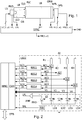
- the figure 2 represents an LSCC control electronic circuit of the light source LS, according to one embodiment.
- the LSCC circuit and connected to the LS source and is connected to the RPRC control device via a CVM conversion module comprising several analog / digital converters and several digital / analog converters.
- the light source LS comprises several LEDs LD1, LD2, LD3, LD4, and a photodiode PHD.
- the LSCC circuit comprises current regulation circuits REG1, REG2, REG3, REG4, adjustable gain amplifiers A1, A2, A3, A4, an amplifier AMP and resistors R1, R2, R3, R4.
- the photodiode PHD is connected via the amplifier AMP to an analog / digital converter of the conversion module CVM, which supplies the device RPRC with digital values of light intensity measurements LFL.
- the cathode of each diode LD1 to LD4 is connected to ground.
- the anode of each diode LD1 to LD4 is connected to the output of one of the amplifiers A1 to A4.
- Each amplifier A1 to A4 is connected to a supply voltage source AV via one of the resistors R1 to R4.
- Each amplifier A1 to A4 receives on a gain control input a current control signal AC1 to AC4 emitted by one of the regulators REG1 to REG4.
- Each regulator REG1 to REG4 performs a measurement of the supply current I1 to I4 of the diode LD1 to LD4 to which it is connected.
- Each regulator REG1 to REG4 receives a target current value LC1 to LC4 supplied in digital form by the regulator RPRC and converted by a digital-to-analog converter. CVM module.
- Each regulator REG1 to REG4 regulates one of the current control signals AC1 to AC4 as a function of the value of the reference current LC1 to LC4 that it receives and as a function of the intensity of the current I1 to I4 that it measures. at the output of the amplifier A1 to A4 whose gain it controls, so that the current I1 to I4 measured corresponds to the value of the target current LC1 to LC4.
- the LSCC circuit or the LS light source may comprise a TSS temperature sensor for measuring the temperature of the LS source.
- the temperature sensor TSS is then connected to an analog digital converter of the CVM module, which supplies the device RPRC with digital values of temperature measurements TPL of the source LS.
- Each regulator REG1 to REG4 can transmit the current measurement I1 to I4 to an analog / digital converter of the CVM module, which in turn transmits a corresponding digital value to the RPRC device.
- the anode of each diode LD1 to LD4 may also be connected to an analog digital converter of the CVM module, which supplies the RPRC device with a digital value representative of the voltage V1 to V4 at the anode of the diode.
- the diodes LD1 to LD4 and possibly the PHD photodiode may be formed on the same semiconductor substrate and integrated in the same component.
- the RPRC device may comprise a connector for connecting by means of a serial or parallel DTB bus to a computer and for transmitting measurement spectra MR (1..n) and an operating state OMD, and possibly other signals for example relating to the measurements made on the spectrometer.
- the LS light source comprises four LEDs. Each LED can emit light having a spectrum of the shape of an asymmetrical Gauss curve.
- the figure 3A represents emission spectra of the diodes LD1 to LD4, in the form of curves C1 to C4 of variation of luminous intensity emitted as a function of the wavelength. Curves C1 to C4 of the figure 3A , were obtained at constant and identical supply current for all the diodes LD1 to LD4.
- the luminous intensity values indicated on the ordinate axis are normalized values.
- the curve C1 of the spectrum of the diode LD1 has a maximum intensity of 1 at a wavelength of about 850 nm.
- Curve C2 of the spectrum of the LD2 diode has a maximum intensity at about 0.92 at a length wave equal to about 890 nm.
- Curve C3 of the spectrum of the LD3 diode has a maximum intensity at about 0.41 at a wavelength of about 940 nm.
- Curve C4 of the spectrum of the LD4 diode has a maximum intensity at about 0.22 at a wavelength of about 970 nm. It can be noted on the figure 3A that the higher the wavelength of the maximum light intensity emitted by the diode LD1 to LD4, the lower this intensity is.
- the figure 3B represents in the form of curves C1 'to C4' of variation of luminous intensity emitted as a function of the wavelength, the emission spectra of the diodes LD1 to LD4 after adjustment of the supply current LC1 to LC4 of each diode LD1 to LD4 by the RPRC controller.
- curves C1 'to C4' all have a maximum normalized intensity value of 1.
- the figure 3B also represents in the form of a CR curve, the combined emission spectrum emitted when the diodes LD1 to LD4 are lit at the same time, with their LC1 to LC4 power supply adjusted. It should be noted that the numerical values appearing in the Figures 3A and 3B are given by way of example and may vary in particular according to the manufacturing conditions of the diodes.
- the figure 4 represents a sequence of steps that can be executed by the RPRC controller.
- the sequence of steps comprises steps S1 to S18.
- the device RPRC adjusts to a set value LCx the supply current (intensity or voltage) of a diode LDx of the light source LS (x varying from 1 to 4 in the example of FIG. Figure 2 ).
- the value LCx is that of a predefined initial value or a value previously applied to the LDx diode.
- the RPRC device receives a light intensity measurement LFL from the photodiode PHD and optionally a temperature measurement TPL from the sensor TSS.
- the RPRC determines by comparison whether the received LFL light intensity and TPL temperature measurements are coherent with each other and with the current LCx supplied to the LDx diode.
- These steps can be performed from charts of variation of the light intensity emitted by a diode LDx as a function of its supply current and its temperature.
- the comparisons made in steps S4 and S5 make it possible to perform a self-diagnosis of the spectrometer in step S6. Thus, if the comparisons made in steps S4 and S5 reveal a malfunction and that the spectrometer is in a normal OMD operating mode, the spectrometer goes into a degraded OMD operating mode DG.
- step S7 the RPRC device determines an optimum integration time ITy of each photosensitive cell y of the OPS sensor by means of a function f1 applied to the light intensity LFL measured in step S2.
- the function f1 can be determined by graphs giving the optimum integration time of each cell y of the OPS sensor, as a function of intensity measurements of the emitted light LFL.
- step S8 the device RPRC compares for each cell y, the integration time ITy obtained at minimum values ITmy and maximum ITMy determined for the cell y. If the integration time ITy is between the minimum and maximum values ITmy, ITMy for each cell y, the device RPRC executes the steps S15 to S17 and then returns to the step S1 to execute a new regulation phase, otherwise it executes step S9.
- step S9 the RPRC device compares the optimum integration time ITy with the minimum integration time ITmy for each cell y for which the test at step S8 has not been verified. If the integration time ITy is less than the integration time ITmy for all or part of the cells y of the OPS sensor, the module RPRC executes the step S10, then the step S12, otherwise (case where the integration time ITy is greater than the maximum integration time ITMy for all or some of the cells y) it executes the steps S11 and S12.
- step S10 the RPRC device decreases by one step STP the LCx supply current of the LED diode LDx. In step S11, the RPRC device increments the LCx feed current of the LDx diode STP step.
- step S12 the RPRC device determines whether the new LCx supply current obtained in step S10 or S11 is between minimum values LCmx and maximum LCMx determined for the LDx diode. If this is the case, the RPRC device returns to step S1 to execute a new regulation phase. In the opposite case, the device RPRC executes step S13 where it tests the operating mode OMD of the spectrometer. If the OMD mode is normal NL, the RPRC device performs step S14 where the OMD operating mode switches to DG degraded mode. If in step S13, the OMD mode is degraded DG, the RPRC device performs step S18, where the OMD mode fails DF.
- steps S10 and S11 if the optimal integration time ITy determined for at least one photosensitive cell is outside the minimum and maximum thresholds ITmy and ITMy, the LCx supplying current of the LED LDx is added to the supply current LCx, a step STP of a certain amplitude, positive or negative (positive if the optimal integration time ITy is greater than the maximum threshold ITMy, and negative if this integration time is lower than the minimum threshold ITmy).
- a new optimal integration time ITy is then again determined in steps S1 to S7 as a function of the new current LCx.
- the execution of the steps S1 to S12 is repeated as long as the optimal integration time ITy is outside the thresholds ITmy and ITMy and as long as the current LCx is between the thresholds LCmx and LCMx.
- step S15 the RPRC device sets the integration time of each cell y of the OPS sensor to its optimum integration time ITy determined in step S7.
- step S16 the RPRC device acquires an MSxy measurement supplied by each cell y with the diode LDx on, as well as optionally, a measurement of the temperature TP of the product to be analyzed in the cell. FLC (TPP) and / or OPS sensor temperature measurement (TPS) and / or LS (TPL) source temperature measurement.
- step S17 the RPRC applies a correction to the measure MSxy using a function f2 and provides a corrected measure MSCxy for each cell y. Function f2 is applied to the measured temperature TP (or measured temperatures) in step S16.
- the sequence of steps S1 to S18 thus makes it possible to obtain a corrected spectrum MSCx (1..n) for each LDx diode.
- the sequence of steps S1 to S15 is thus executed for each LDx diode of the source LS in order to obtain at least one MSCx spectrum (1..n) for each LDx diode.
- the weighting coefficients Pxy can be adjusted to give more importance to the useful signal in the resulting spectrum.
- the signals of the cells therein measuring the highest raw signals, and therefore providing the most reliable information (high signal-to-noise ratio) are associated with a higher weighting coefficient Pxy.
- the weighting coefficients Pxy are determined during the calibration phase and depend on the temperature TPL of the source LS.
- the resultant spectrum MR (1..n) obtained can furthermore be averaged with several other successive spectra obtained, in order to obtain a spectrum that can be exploited by a device for regulating the operating parameters of a device. thermal motor.
- the number of MR spectra (1..n) used for this averaging can be increased as the transition from the normal OMD operating mode NL to the degraded DG mode.
- the number of spectra obtained to average in normal mode can be of the order of 5 to 20, and in degraded mode, of the order of 100.
- step S15 the integration time ITy of all the photosensitive cells y of the OPS sensor can be set globally to the smallest integration time determined in step S7 for each cell y.
- the RPRC device performs a self-diagnosis of the spectrometer by distinguishing three modes of OMD operation of the spectrometer: the normal operating mode NL in which the spectrometer produces actionable measurements , DG degraded operating mode in which the spectrometer always produces actionable measurements, but in abnormal conditions, and a fault mode DF in which the spectrometer is considered faulty and can no longer provide a usable measurement.
- the normal operating mode NL in which the spectrometer produces actionable measurements
- DG degraded operating mode in which the spectrometer always produces actionable measurements, but in abnormal conditions
- a fault mode DF in which the spectrometer is considered faulty and can no longer provide a usable measurement.
- the time to provide a measurement is greatly increased or the degree of confidence in the measurements provided decreases (may be at the discretion of the user).
- the fault mode DF is detected, for example, when the luminous intensity LFL measured by the photodiode PHD does not correspond to the current LCx supplied to one of the LEDs of the source LS or to the temperature TPS of the source LS.
- the RPRC device may output a self-diagnostic signal indicating the OMD operating mode of the spectrometer. This signal can be transmitted for example to an on-board computer of the vehicle in which the spectrometer is embedded.
- the figure 5 represents a graph of the LCx setpoint current supplied to an LED LDx of the LS source (ordinate axis) as a function of light intensity LFL or temperature TPL, measured in the source LS (abscissa axis).
- This graph presents four lines D1, D2, D3, D4 passing through the origin O of the graph.
- the lines D1 and D2 delimit between them an operating zone 1 corresponding to the normal operating mode NL in which the LCx current supplied to an LED LDx of the source LS, the temperature TPL of the source and / or the luminous intensity LFL measured values have normal values (neither too low nor too high).
- the ordinate axis and the line D3 delimit between them an area 3a.
- Zones 3a and 3b correspond to fault mode DF in which the LCx current supplied to an LDx diode of the light source is strong and the light intensity supplied by the source is abnormally low, or in which the current supplied to the diode LDx is low and the temperature of the TPL source is abnormally high. Between zone 1 and zones 3a and 3b are zones 2a and 2b corresponding to the degraded operating mode DG.
- the minimum values LCmx and maximum LCMx of the supply current of each LDx diode result from tests carried out during a calibration phase to determine the ideal operating range of each of the light emitting diodes of the source LS.
- the maximum value LCMx is determined so as not to accelerate the aging of the diode.
- the minimum value LCmx may be chosen so as to ensure repeatability and stability of the luminous flux emitted by the diode.
- the minimum values ITmy and maximum ITMy of each cell y of the OPS sensor are also determined during the calibration phase by tests making it possible to determine an ideal operating range of the photosensitive cells y of the OPS sensor, considered independently or as a whole.
- the maximum value ITMy is determined in order to avoid saturation of the photosensitive cell y.
- the minimum value ITmy is determined so as to obtain a stable and repeatable signal, while respecting a minimum target value of signal / noise ratio, previously defined.
- the functions f1 and f2 used in steps S7 and S17 can be determined during the calibration phase.
- the function f1 giving the optimal integration time ITy of each cell y of the sensor OPS as a function of the light intensity LFL measured by the photodiode PHD can be determined using one or more reference products, fluids or solids, with which a series of tests is performed. For each of the reference products, the luminous intensity LFL measured by the photodiode PHD is varied by varying the LCx supply current of the LED diode LDx.
- the optimal integration time ITy of each cell y is sought, that is to say an integration time making it possible to obtain a luminous flux measured by the cell y, which is stable and constant, that is to say substantially independent of the luminous flux emitted by the source LS. Measurement torques are thus obtained (luminous intensity LFL measured by the photodiode PHD - optimal integration time ITy).
- the temperature of the source TPL if it is available, is also collected, as well as the product temperature TPP and the corresponding LCx current setpoint.
- the variations of the luminous intensity LFL measured by the photodiode PHD are such that for a part of the measurements made, the optimal integration time ITy is outside the predefined threshold values ITmy, ITMy. From the measurement pairs, one establishes either correspondence tables, abacuses or predictive models, making it possible to determine the optimal integration time ITy of each cell y as a function of the light intensity LFL measured by the photodiode PHD. From the data thus collected, minimum and maximum values of correspondence between the luminous intensity LFL measured by the photodiode PHD and the temperature TPL of the source LS (if this is available), and between the luminous intensity, are determined. LFL and LCx power supply value of LED LDx. These minimum and maximum match values are used in steps S4 and S5 to self-diagnose the spectrometer.
- the function f2 making it possible to correct the measurement of the luminous intensity MSxy supplied by the cell y as a function of the temperature TP can be determined by a series of tests during which the temperature TPL of the source LS is varied independently.
- TPS temperature of the OPS sensor and the TPP temperature of the product to be analyzed range from -40 to + 105 ° C, or ideally from -50 to + 150 ° C with at least one fluid or solid reference product.
- the MSxy intensity measurement values, LCx setpoint current and temperature are collected.
- the abacuses obtained make it possible to determine a corrected measure of luminous intensity MSCxy at the reference temperature as a function of the measurement of luminous intensity MSxy measured at ambient temperature by each photosensitive cell y, as a function of the temperatures TPL, TPP, TPS of the source LS, of the product in the measuring cell FLC and the OPS sensor, and as a function of the integration time ITy and the supply current LCx of the LED diode LDx.
- the spectrometer which has just been described can thus function in a very wide range of temperatures, including with very large temperature differences between the product to be analyzed and the LS light source. It should be noted that this arrangement is obtained without using a complex reference channel requiring a second sensor which directly receives the light emitted by the source, as proposed in the patent application. FR 2 940 447 , but only with a measurement of the luminous intensity LFL emitted by the source LS, therefore at a lower cost and without increasing the bulk of the spectrometer.
- the regulation carried out by the sequence of steps S1 to S18 can be carried out on the basis of the temperature of the source TPL and / or the product to be analyzed TPP. , or on the basis of voltages Vx or currents Ix (x being between 1 and 4 in the example of the figure 2 ) measured in the circuit of the figure 2 .
- the temperature TPL and / or the voltages Vx and / or the currents Ix can be used to check the correct operation of the photodiode PHD and the temperature sensor TSS.
- control method is not limited to the use of light-emitting diodes as a light source.
- control method described above can be applied to any light source, whose emitted light intensity can be adjusted by the power supply of the light source.
- control method can be applied to other spectrometers than the one described with reference to FIG. figure 1 . It is simply important that the integration time of the spectrometer sensor can be adjusted, and that the spectrometer can provide representative measurements of the operation of the light source.
- the correction step of the spectral measurements obtained to take into account the temperature of the various components of the spectrometer is also not necessary. It may indeed be considered to place the spectrometer in an enclosure whose temperature is kept constant, or to make a spectrum measurement only when the temperature of the spectrometer has reached a set temperature.
Landscapes
- Physics & Mathematics (AREA)
- Spectroscopy & Molecular Physics (AREA)
- General Physics & Mathematics (AREA)
- Immunology (AREA)
- Chemical & Material Sciences (AREA)
- Analytical Chemistry (AREA)
- Biochemistry (AREA)
- General Health & Medical Sciences (AREA)
- Health & Medical Sciences (AREA)
- Life Sciences & Earth Sciences (AREA)
- Pathology (AREA)
- Engineering & Computer Science (AREA)
- Mathematical Physics (AREA)
- Theoretical Computer Science (AREA)
- Investigating Or Analysing Materials By Optical Means (AREA)
- Spectrometry And Color Measurement (AREA)
- Investigating, Analyzing Materials By Fluorescence Or Luminescence (AREA)
- Optical Measuring Cells (AREA)
Applications Claiming Priority (3)
| Application Number | Priority Date | Filing Date | Title |
|---|---|---|---|
| FR1261757A FR2999333A1 (fr) | 2012-12-07 | 2012-12-07 | Procede et dispositif embarque d’analyse de fluide dans un moteur thermique |
| FR1261758A FR2999334B1 (fr) | 2012-12-07 | 2012-12-07 | Procede et dispositif embarque d’analyse de fluide dans un moteur thermique |
| PCT/FR2013/052940 WO2014087102A1 (fr) | 2012-12-07 | 2013-12-04 | Procede et dispositif embarque d'analyse de fluide dans un moteur thermique |
Publications (2)
| Publication Number | Publication Date |
|---|---|
| EP2929321A1 EP2929321A1 (fr) | 2015-10-14 |
| EP2929321B1 true EP2929321B1 (fr) | 2019-06-05 |
Family
ID=49886962
Family Applications (2)
| Application Number | Title | Priority Date | Filing Date |
|---|---|---|---|
| EP13815047.9A Active EP2929321B1 (fr) | 2012-12-07 | 2013-12-04 | Procede et dispositif embarque d'analyse de fluide dans un moteur thermique |
| EP13815048.7A Active EP2929322B1 (fr) | 2012-12-07 | 2013-12-04 | Procédé et dispositif embarque d'analyse de fluide dans un moteur thermique |
Family Applications After (1)
| Application Number | Title | Priority Date | Filing Date |
|---|---|---|---|
| EP13815048.7A Active EP2929322B1 (fr) | 2012-12-07 | 2013-12-04 | Procédé et dispositif embarque d'analyse de fluide dans un moteur thermique |
Country Status (10)
Families Citing this family (2)
| Publication number | Priority date | Publication date | Assignee | Title |
|---|---|---|---|---|
| DE102014111093A1 (de) * | 2014-08-05 | 2016-02-11 | Valeo Schalter Und Sensoren Gmbh | Sensorvorrichtung zum Bestimmen einer Konzentration eines Fluids, Fahrerassistenzsystem, Kraftfahrzeug sowie Verfahren |
| TWI750706B (zh) * | 2020-06-20 | 2021-12-21 | 丁逸聖 | 發光裝置、發光方法、光檢測裝置、光譜檢測方法及發光修正方法 |
Family Cites Families (29)
| Publication number | Priority date | Publication date | Assignee | Title |
|---|---|---|---|---|
| JPS54125089A (en) * | 1978-03-22 | 1979-09-28 | Matsushita Electric Ind Co Ltd | Smoke detector |
| GB2191574B (en) * | 1986-06-16 | 1989-12-20 | Philips Electronic Associated | Method of and apparatus for spectroscopically analysing samples |
| FI77736C (fi) | 1987-06-25 | 1989-04-10 | Valtion Teknillinen | Foerfarande foer reglering av straolkaella och reglerbar straolkaella. |
| US5477853A (en) | 1992-12-01 | 1995-12-26 | Somanetics Corporation | Temperature compensation method and apparatus for spectroscopic devices |
| JP3235249B2 (ja) * | 1992-12-18 | 2001-12-04 | 株式会社デンソー | 光学的情報読取り装置 |
| FI103074B (fi) * | 1996-07-17 | 1999-04-15 | Valtion Teknillinen | Spektrometri |
| US6356774B1 (en) * | 1998-09-29 | 2002-03-12 | Mallinckrodt, Inc. | Oximeter sensor with encoded temperature characteristic |
| US7423750B2 (en) * | 2001-11-29 | 2008-09-09 | Applera Corporation | Configurations, systems, and methods for optical scanning with at least one first relative angular motion and at least one second angular motion or at least one linear motion |
| JP2001268324A (ja) * | 2000-01-12 | 2001-09-28 | Fuji Photo Film Co Ltd | 光源装置、原稿読取装置及び方法 |
| JP2001223861A (ja) * | 2000-02-14 | 2001-08-17 | Fuji Photo Film Co Ltd | 画像読取装置および画像読取方法 |
| US6617560B2 (en) * | 2001-05-30 | 2003-09-09 | Watt Stopper, Inc. | Lighting control circuit including LED for detecting exposure to radiation |
| US7116354B2 (en) * | 2001-06-20 | 2006-10-03 | Xenogen Corporation | Absolute intensity determination for a light source in low level light imaging systems |
| CA2460205C (en) * | 2001-12-31 | 2005-05-03 | R J Doran & Co Ltd. | Led inspection lamp and led spot light |
| JP3620798B2 (ja) * | 2003-06-27 | 2005-02-16 | 株式会社アステム | 非破壊分光測定器 |
| US9075008B2 (en) * | 2003-11-07 | 2015-07-07 | Kyle H. Holland | Plant treatment based on a water invariant chlorophyll index |
| US7329887B2 (en) * | 2003-12-02 | 2008-02-12 | 3M Innovative Properties Company | Solid state light device |
| FR2866956B1 (fr) * | 2004-02-26 | 2006-05-19 | Cit Alcatel | Detection d'especes gazeuses minoritaires par spectroscopie d'emission optique |
| DE102004025448B4 (de) * | 2004-05-19 | 2007-03-29 | Bruker Optik Gmbh | Verfahren zum Messen eines Spektrums einer Messprobe mittels eines Infrarot-Spektrometers und derartiges Infrarot-Spektrometer |
| US20060072319A1 (en) | 2004-10-05 | 2006-04-06 | Dziekan Michael E | Method of using light emitting diodes for illumination sensing and using ultra-violet light sources for white light illumination |
| US7938643B2 (en) * | 2006-01-07 | 2011-05-10 | Medical College Of Georgia Research Institute, Inc. | Use of integrating sphere technology to provide uniform, high-intensity light, and wavelength mixing from light emitting diodes |
| US8296088B2 (en) * | 2006-06-02 | 2012-10-23 | Luminex Corporation | Systems and methods for performing measurements of one or more materials |
| WO2008129453A1 (en) | 2007-04-20 | 2008-10-30 | Koninklijke Philips Electronics N.V. | Lighting device with a led used for sensing |
| US7601950B2 (en) * | 2007-09-25 | 2009-10-13 | Baker Hughes Incorporated | System and method for downhole optical analysis |
| CA2732996A1 (en) | 2008-08-07 | 2010-05-14 | University Of Massachusetts | Spectroscopic sensors |
| FR2940447B1 (fr) * | 2008-12-23 | 2011-10-21 | Continental Automotive France | Spectrometre miniature embarque dans un vehicule automobile a detecteur de mesure et detecteur de reference unique |
| US9173600B2 (en) * | 2009-03-09 | 2015-11-03 | S.E.A. Medical Systems, Inc. | Systems and methods for the identification of compounds in medical fluids using admittance spectroscopy |
| US9052276B2 (en) * | 2009-06-08 | 2015-06-09 | S.E.A. Medical Systems, Inc. | Systems and methods for the identification of compounds using admittance spectroscopy |
| RU2427822C1 (ru) * | 2009-12-03 | 2011-08-27 | Учреждение Российской академии наук Центр фотохимии РАН | Способ анализа содержания летучих органических соединений в газовой среде и матричный анализатор для его осуществления |
| US20130031644A1 (en) * | 2011-05-23 | 2013-01-31 | University Of Tennessee Research Foundation | Autonomous lux reporter system and methods of use |
-
2013
- 2013-12-04 BR BR112015013222A patent/BR112015013222A2/pt not_active IP Right Cessation
- 2013-12-04 BR BR112015013313A patent/BR112015013313A2/pt not_active IP Right Cessation
- 2013-12-04 US US14/648,874 patent/US9562851B2/en not_active Expired - Fee Related
- 2013-12-04 CN CN201380072189.9A patent/CN104969058B/zh active Active
- 2013-12-04 KR KR1020157017680A patent/KR20150114465A/ko not_active Withdrawn
- 2013-12-04 RU RU2015127029A patent/RU2637388C2/ru active
- 2013-12-04 EP EP13815047.9A patent/EP2929321B1/fr active Active
- 2013-12-04 US US14/648,855 patent/US9562850B2/en not_active Expired - Fee Related
- 2013-12-04 WO PCT/FR2013/052940 patent/WO2014087102A1/fr active Application Filing
- 2013-12-04 CN CN201380072190.1A patent/CN104969059A/zh active Pending
- 2013-12-04 EP EP13815048.7A patent/EP2929322B1/fr active Active
- 2013-12-04 MX MX2015007174A patent/MX342198B/es active IP Right Grant
- 2013-12-04 CA CA2892849A patent/CA2892849A1/fr not_active Abandoned
- 2013-12-04 JP JP2015546080A patent/JP2016501372A/ja active Pending
- 2013-12-04 WO PCT/FR2013/052941 patent/WO2014087103A1/fr active Application Filing
- 2013-12-04 RU RU2015127030A patent/RU2015127030A/ru not_active Application Discontinuation
Non-Patent Citations (1)
| Title |
|---|
| None * |
Also Published As
| Publication number | Publication date |
|---|---|
| BR112015013313A2 (pt) | 2017-07-11 |
| RU2015127030A (ru) | 2017-01-13 |
| US9562850B2 (en) | 2017-02-07 |
| MX342198B (es) | 2016-09-20 |
| CN104969058B (zh) | 2017-08-08 |
| US20150346085A1 (en) | 2015-12-03 |
| JP2016501372A (ja) | 2016-01-18 |
| KR20150114465A (ko) | 2015-10-12 |
| BR112015013222A2 (pt) | 2017-07-11 |
| RU2015127029A (ru) | 2017-01-12 |
| WO2014087102A1 (fr) | 2014-06-12 |
| RU2637388C2 (ru) | 2017-12-04 |
| EP2929322A1 (fr) | 2015-10-14 |
| WO2014087103A1 (fr) | 2014-06-12 |
| US9562851B2 (en) | 2017-02-07 |
| CN104969059A (zh) | 2015-10-07 |
| EP2929321A1 (fr) | 2015-10-14 |
| CN104969058A (zh) | 2015-10-07 |
| US20150300951A1 (en) | 2015-10-22 |
| MX2015007174A (es) | 2015-10-20 |
| EP2929322B1 (fr) | 2016-10-12 |
| CA2892849A1 (fr) | 2014-06-12 |
Similar Documents
| Publication | Publication Date | Title |
|---|---|---|
| JP5605687B2 (ja) | 分光特性測定方法、分光特性測定装置及びこれを備えた画像形成装置 | |
| FR2776771A1 (fr) | Procede d'etalonnage en longueur d'onde d'un dispositif de filtrage d'un rayonnement electromagnetique | |
| EP2929321B1 (fr) | Procede et dispositif embarque d'analyse de fluide dans un moteur thermique | |
| EP4010685B1 (fr) | Procédé d'analyse d'un gaz par un capteur optique | |
| EP1272863B1 (fr) | Dispositif et procede de mesure de champ(s) magnetique(s) a calibration superposee a la mesure, et applications correspondantes | |
| US20040263844A1 (en) | Method and apparatus for measuring bandwidth of an optical spectrum output of a very small wavelength very narrow bandwidth high power laser | |
| WO2009150325A1 (fr) | Mesureur d'absorption, tel que notamment colorimètre, dans la gamme spectrale visible, infrarouge ou encore ultraviolet, pour l'analyse d'un fluide en transmission | |
| FR2999333A1 (fr) | Procede et dispositif embarque d’analyse de fluide dans un moteur thermique | |
| CN114062286A (zh) | 气体分析系统及气体分析方法 | |
| FR2999334A1 (fr) | Procede et dispositif embarque d’analyse de fluide dans un moteur thermique | |
| WO2008152286A2 (fr) | Procede de teledetection optique de composes dans un milieu | |
| RU2334216C1 (ru) | Устройство для измерения количества химических веществ, содержащихся в газовой среде | |
| Wiesent et al. | Linear variable filter based oil condition monitoring systems for offshore windturbines | |
| EP3485248B1 (fr) | Procédé et dispositif de caractérisation d'une source optique | |
| US12372405B2 (en) | Reference material for and method of calibrating Raman spectrometers | |
| EP3749948A1 (fr) | Procédé d'analyse d'un gaz par une double illumination | |
| US20250052668A1 (en) | Calibration material and method for calibrating spectral responsivity of raman spectrometers | |
| WO2025036782A1 (fr) | Systeme de controle de depot de couches minces comportant une source de lumiere continue et une cavite optique | |
| EP4281756A1 (fr) | Procede de calibration d'un capteur de gaz et procede de mesure d'un gaz mettant en oeuvre la calibration | |
| WO2025036783A1 (fr) | Systeme de controle de depot de couches minces comportant une source de lumiere continue et un spectrometre | |
| HEAPS et al. | Precision measurement of atmospheric trace constituents using a compact fabry-perot radiometer | |
| EP2189750B1 (fr) | Procédé de calibration des gains interpixels d'un interféromètre | |
| Giovanelli et al. | Performance of a diode-array spectrometer in DOAS applications | |
| FR3070559A1 (fr) | Procede et dispositif de caracterisation d'un module photovoltaique |
Legal Events
| Date | Code | Title | Description |
|---|---|---|---|
| PUAI | Public reference made under article 153(3) epc to a published international application that has entered the european phase |
Free format text: ORIGINAL CODE: 0009012 |
|
| 17P | Request for examination filed |
Effective date: 20150603 |
|
| AK | Designated contracting states |
Kind code of ref document: A1 Designated state(s): AL AT BE BG CH CY CZ DE DK EE ES FI FR GB GR HR HU IE IS IT LI LT LU LV MC MK MT NL NO PL PT RO RS SE SI SK SM TR |
|
| AX | Request for extension of the european patent |
Extension state: BA ME |
|
| DAX | Request for extension of the european patent (deleted) | ||
| 17Q | First examination report despatched |
Effective date: 20160713 |
|
| STAA | Information on the status of an ep patent application or granted ep patent |
Free format text: STATUS: EXAMINATION IS IN PROGRESS |
|
| REG | Reference to a national code |
Ref country code: DE Ref legal event code: R079 Ref document number: 602013056283 Country of ref document: DE Free format text: PREVIOUS MAIN CLASS: G01N0021350000 Ipc: G01N0021357700 |
|
| RIC1 | Information provided on ipc code assigned before grant |
Ipc: G01N 21/3577 20140101AFI20181108BHEP Ipc: G01N 21/31 20060101ALN20181108BHEP Ipc: G01N 21/3504 20140101ALI20181108BHEP Ipc: G01N 21/27 20060101ALI20181108BHEP |
|
| GRAP | Despatch of communication of intention to grant a patent |
Free format text: ORIGINAL CODE: EPIDOSNIGR1 |
|
| STAA | Information on the status of an ep patent application or granted ep patent |
Free format text: STATUS: GRANT OF PATENT IS INTENDED |
|
| RIC1 | Information provided on ipc code assigned before grant |
Ipc: G01N 21/27 20060101ALI20181113BHEP Ipc: G01N 21/3504 20140101ALI20181113BHEP Ipc: G01N 21/3577 20140101AFI20181113BHEP Ipc: G01N 21/31 20060101ALN20181113BHEP |
|
| RIC1 | Information provided on ipc code assigned before grant |
Ipc: G01N 21/3577 20140101AFI20181203BHEP Ipc: G01N 21/31 20060101ALN20181203BHEP Ipc: G01N 21/3504 20140101ALI20181203BHEP Ipc: G01N 21/27 20060101ALI20181203BHEP |
|
| INTG | Intention to grant announced |
Effective date: 20181219 |
|
| RIC1 | Information provided on ipc code assigned before grant |
Ipc: G01N 21/27 20060101ALI20181207BHEP Ipc: G01N 21/3504 20140101ALI20181207BHEP Ipc: G01N 21/31 20060101ALN20181207BHEP Ipc: G01N 21/3577 20140101AFI20181207BHEP |
|
| GRAS | Grant fee paid |
Free format text: ORIGINAL CODE: EPIDOSNIGR3 |
|
| GRAA | (expected) grant |
Free format text: ORIGINAL CODE: 0009210 |
|
| STAA | Information on the status of an ep patent application or granted ep patent |
Free format text: STATUS: THE PATENT HAS BEEN GRANTED |
|
| AK | Designated contracting states |
Kind code of ref document: B1 Designated state(s): AL AT BE BG CH CY CZ DE DK EE ES FI FR GB GR HR HU IE IS IT LI LT LU LV MC MK MT NL NO PL PT RO RS SE SI SK SM TR |
|
| REG | Reference to a national code |
Ref country code: GB Ref legal event code: FG4D Free format text: NOT ENGLISH |
|
| REG | Reference to a national code |
Ref country code: CH Ref legal event code: EP |
|
| REG | Reference to a national code |
Ref country code: AT Ref legal event code: REF Ref document number: 1140513 Country of ref document: AT Kind code of ref document: T Effective date: 20190615 |
|
| REG | Reference to a national code |
Ref country code: DE Ref legal event code: R096 Ref document number: 602013056283 Country of ref document: DE |
|
| REG | Reference to a national code |
Ref country code: IE Ref legal event code: FG4D Free format text: LANGUAGE OF EP DOCUMENT: FRENCH |
|
| REG | Reference to a national code |
Ref country code: NL Ref legal event code: MP Effective date: 20190605 |
|
| REG | Reference to a national code |
Ref country code: LT Ref legal event code: MG4D |
|
| PG25 | Lapsed in a contracting state [announced via postgrant information from national office to epo] |
Ref country code: SE Free format text: LAPSE BECAUSE OF FAILURE TO SUBMIT A TRANSLATION OF THE DESCRIPTION OR TO PAY THE FEE WITHIN THE PRESCRIBED TIME-LIMIT Effective date: 20190605 Ref country code: AL Free format text: LAPSE BECAUSE OF FAILURE TO SUBMIT A TRANSLATION OF THE DESCRIPTION OR TO PAY THE FEE WITHIN THE PRESCRIBED TIME-LIMIT Effective date: 20190605 Ref country code: LT Free format text: LAPSE BECAUSE OF FAILURE TO SUBMIT A TRANSLATION OF THE DESCRIPTION OR TO PAY THE FEE WITHIN THE PRESCRIBED TIME-LIMIT Effective date: 20190605 Ref country code: ES Free format text: LAPSE BECAUSE OF FAILURE TO SUBMIT A TRANSLATION OF THE DESCRIPTION OR TO PAY THE FEE WITHIN THE PRESCRIBED TIME-LIMIT Effective date: 20190605 Ref country code: HR Free format text: LAPSE BECAUSE OF FAILURE TO SUBMIT A TRANSLATION OF THE DESCRIPTION OR TO PAY THE FEE WITHIN THE PRESCRIBED TIME-LIMIT Effective date: 20190605 Ref country code: NO Free format text: LAPSE BECAUSE OF FAILURE TO SUBMIT A TRANSLATION OF THE DESCRIPTION OR TO PAY THE FEE WITHIN THE PRESCRIBED TIME-LIMIT Effective date: 20190905 Ref country code: FI Free format text: LAPSE BECAUSE OF FAILURE TO SUBMIT A TRANSLATION OF THE DESCRIPTION OR TO PAY THE FEE WITHIN THE PRESCRIBED TIME-LIMIT Effective date: 20190605 |
|
| PG25 | Lapsed in a contracting state [announced via postgrant information from national office to epo] |
Ref country code: GR Free format text: LAPSE BECAUSE OF FAILURE TO SUBMIT A TRANSLATION OF THE DESCRIPTION OR TO PAY THE FEE WITHIN THE PRESCRIBED TIME-LIMIT Effective date: 20190906 Ref country code: BG Free format text: LAPSE BECAUSE OF FAILURE TO SUBMIT A TRANSLATION OF THE DESCRIPTION OR TO PAY THE FEE WITHIN THE PRESCRIBED TIME-LIMIT Effective date: 20190905 Ref country code: RS Free format text: LAPSE BECAUSE OF FAILURE TO SUBMIT A TRANSLATION OF THE DESCRIPTION OR TO PAY THE FEE WITHIN THE PRESCRIBED TIME-LIMIT Effective date: 20190605 Ref country code: LV Free format text: LAPSE BECAUSE OF FAILURE TO SUBMIT A TRANSLATION OF THE DESCRIPTION OR TO PAY THE FEE WITHIN THE PRESCRIBED TIME-LIMIT Effective date: 20190605 |
|
| REG | Reference to a national code |
Ref country code: AT Ref legal event code: MK05 Ref document number: 1140513 Country of ref document: AT Kind code of ref document: T Effective date: 20190605 |
|
| PG25 | Lapsed in a contracting state [announced via postgrant information from national office to epo] |
Ref country code: AT Free format text: LAPSE BECAUSE OF FAILURE TO SUBMIT A TRANSLATION OF THE DESCRIPTION OR TO PAY THE FEE WITHIN THE PRESCRIBED TIME-LIMIT Effective date: 20190605 Ref country code: NL Free format text: LAPSE BECAUSE OF FAILURE TO SUBMIT A TRANSLATION OF THE DESCRIPTION OR TO PAY THE FEE WITHIN THE PRESCRIBED TIME-LIMIT Effective date: 20190605 Ref country code: EE Free format text: LAPSE BECAUSE OF FAILURE TO SUBMIT A TRANSLATION OF THE DESCRIPTION OR TO PAY THE FEE WITHIN THE PRESCRIBED TIME-LIMIT Effective date: 20190605 Ref country code: PT Free format text: LAPSE BECAUSE OF FAILURE TO SUBMIT A TRANSLATION OF THE DESCRIPTION OR TO PAY THE FEE WITHIN THE PRESCRIBED TIME-LIMIT Effective date: 20191007 Ref country code: SK Free format text: LAPSE BECAUSE OF FAILURE TO SUBMIT A TRANSLATION OF THE DESCRIPTION OR TO PAY THE FEE WITHIN THE PRESCRIBED TIME-LIMIT Effective date: 20190605 Ref country code: CZ Free format text: LAPSE BECAUSE OF FAILURE TO SUBMIT A TRANSLATION OF THE DESCRIPTION OR TO PAY THE FEE WITHIN THE PRESCRIBED TIME-LIMIT Effective date: 20190605 Ref country code: RO Free format text: LAPSE BECAUSE OF FAILURE TO SUBMIT A TRANSLATION OF THE DESCRIPTION OR TO PAY THE FEE WITHIN THE PRESCRIBED TIME-LIMIT Effective date: 20190605 |
|
| PG25 | Lapsed in a contracting state [announced via postgrant information from national office to epo] |
Ref country code: IT Free format text: LAPSE BECAUSE OF FAILURE TO SUBMIT A TRANSLATION OF THE DESCRIPTION OR TO PAY THE FEE WITHIN THE PRESCRIBED TIME-LIMIT Effective date: 20190605 Ref country code: SM Free format text: LAPSE BECAUSE OF FAILURE TO SUBMIT A TRANSLATION OF THE DESCRIPTION OR TO PAY THE FEE WITHIN THE PRESCRIBED TIME-LIMIT Effective date: 20190605 Ref country code: IS Free format text: LAPSE BECAUSE OF FAILURE TO SUBMIT A TRANSLATION OF THE DESCRIPTION OR TO PAY THE FEE WITHIN THE PRESCRIBED TIME-LIMIT Effective date: 20191005 |
|
| REG | Reference to a national code |
Ref country code: DE Ref legal event code: R097 Ref document number: 602013056283 Country of ref document: DE |
|
| PG25 | Lapsed in a contracting state [announced via postgrant information from national office to epo] |
Ref country code: TR Free format text: LAPSE BECAUSE OF FAILURE TO SUBMIT A TRANSLATION OF THE DESCRIPTION OR TO PAY THE FEE WITHIN THE PRESCRIBED TIME-LIMIT Effective date: 20190605 |
|
| PLBE | No opposition filed within time limit |
Free format text: ORIGINAL CODE: 0009261 |
|
| STAA | Information on the status of an ep patent application or granted ep patent |
Free format text: STATUS: NO OPPOSITION FILED WITHIN TIME LIMIT |
|
| PG25 | Lapsed in a contracting state [announced via postgrant information from national office to epo] |
Ref country code: PL Free format text: LAPSE BECAUSE OF FAILURE TO SUBMIT A TRANSLATION OF THE DESCRIPTION OR TO PAY THE FEE WITHIN THE PRESCRIBED TIME-LIMIT Effective date: 20190605 Ref country code: DK Free format text: LAPSE BECAUSE OF FAILURE TO SUBMIT A TRANSLATION OF THE DESCRIPTION OR TO PAY THE FEE WITHIN THE PRESCRIBED TIME-LIMIT Effective date: 20190605 |
|
| 26N | No opposition filed |
Effective date: 20200306 |
|
| PG25 | Lapsed in a contracting state [announced via postgrant information from national office to epo] |
Ref country code: SI Free format text: LAPSE BECAUSE OF FAILURE TO SUBMIT A TRANSLATION OF THE DESCRIPTION OR TO PAY THE FEE WITHIN THE PRESCRIBED TIME-LIMIT Effective date: 20190605 |
|
| REG | Reference to a national code |
Ref country code: CH Ref legal event code: PL |
|
| REG | Reference to a national code |
Ref country code: BE Ref legal event code: MM Effective date: 20191231 |
|
| PG25 | Lapsed in a contracting state [announced via postgrant information from national office to epo] |
Ref country code: MC Free format text: LAPSE BECAUSE OF FAILURE TO SUBMIT A TRANSLATION OF THE DESCRIPTION OR TO PAY THE FEE WITHIN THE PRESCRIBED TIME-LIMIT Effective date: 20190605 |
|
| PG25 | Lapsed in a contracting state [announced via postgrant information from national office to epo] |
Ref country code: LU Free format text: LAPSE BECAUSE OF NON-PAYMENT OF DUE FEES Effective date: 20191204 Ref country code: IE Free format text: LAPSE BECAUSE OF NON-PAYMENT OF DUE FEES Effective date: 20191204 |
|
| PG25 | Lapsed in a contracting state [announced via postgrant information from national office to epo] |
Ref country code: LI Free format text: LAPSE BECAUSE OF NON-PAYMENT OF DUE FEES Effective date: 20191231 Ref country code: BE Free format text: LAPSE BECAUSE OF NON-PAYMENT OF DUE FEES Effective date: 20191231 Ref country code: CH Free format text: LAPSE BECAUSE OF NON-PAYMENT OF DUE FEES Effective date: 20191231 |
|
| PG25 | Lapsed in a contracting state [announced via postgrant information from national office to epo] |
Ref country code: CY Free format text: LAPSE BECAUSE OF FAILURE TO SUBMIT A TRANSLATION OF THE DESCRIPTION OR TO PAY THE FEE WITHIN THE PRESCRIBED TIME-LIMIT Effective date: 20190605 |
|
| PG25 | Lapsed in a contracting state [announced via postgrant information from national office to epo] |
Ref country code: MT Free format text: LAPSE BECAUSE OF FAILURE TO SUBMIT A TRANSLATION OF THE DESCRIPTION OR TO PAY THE FEE WITHIN THE PRESCRIBED TIME-LIMIT Effective date: 20190605 Ref country code: HU Free format text: LAPSE BECAUSE OF FAILURE TO SUBMIT A TRANSLATION OF THE DESCRIPTION OR TO PAY THE FEE WITHIN THE PRESCRIBED TIME-LIMIT; INVALID AB INITIO Effective date: 20131204 |
|
| PG25 | Lapsed in a contracting state [announced via postgrant information from national office to epo] |
Ref country code: MK Free format text: LAPSE BECAUSE OF FAILURE TO SUBMIT A TRANSLATION OF THE DESCRIPTION OR TO PAY THE FEE WITHIN THE PRESCRIBED TIME-LIMIT Effective date: 20190605 |
|
| PGFP | Annual fee paid to national office [announced via postgrant information from national office to epo] |
Ref country code: GB Payment date: 20231121 Year of fee payment: 11 |
|
| PGFP | Annual fee paid to national office [announced via postgrant information from national office to epo] |
Ref country code: FR Payment date: 20231219 Year of fee payment: 11 Ref country code: DE Payment date: 20231121 Year of fee payment: 11 |
|
| REG | Reference to a national code |
Ref country code: DE Ref legal event code: R119 Ref document number: 602013056283 Country of ref document: DE |
|
| GBPC | Gb: european patent ceased through non-payment of renewal fee |
Effective date: 20241204 |