EP2929305B1 - Method of vibration measurement and interferometer - Google Patents
Method of vibration measurement and interferometer Download PDFInfo
- Publication number
- EP2929305B1 EP2929305B1 EP13860879.9A EP13860879A EP2929305B1 EP 2929305 B1 EP2929305 B1 EP 2929305B1 EP 13860879 A EP13860879 A EP 13860879A EP 2929305 B1 EP2929305 B1 EP 2929305B1
- Authority
- EP
- European Patent Office
- Prior art keywords
- plane
- illumination light
- light beams
- directions
- interferometer
- Prior art date
- Legal status (The legal status is an assumption and is not a legal conclusion. Google has not performed a legal analysis and makes no representation as to the accuracy of the status listed.)
- Active
Links
Images


Classifications
-
- G—PHYSICS
- G01—MEASURING; TESTING
- G01H—MEASUREMENT OF MECHANICAL VIBRATIONS OR ULTRASONIC, SONIC OR INFRASONIC WAVES
- G01H9/00—Measuring mechanical vibrations or ultrasonic, sonic or infrasonic waves by using radiation-sensitive means, e.g. optical means
-
- G—PHYSICS
- G01—MEASURING; TESTING
- G01J—MEASUREMENT OF INTENSITY, VELOCITY, SPECTRAL CONTENT, POLARISATION, PHASE OR PULSE CHARACTERISTICS OF INFRARED, VISIBLE OR ULTRAVIOLET LIGHT; COLORIMETRY; RADIATION PYROMETRY
- G01J9/00—Measuring optical phase difference; Determining degree of coherence; Measuring optical wavelength
- G01J9/02—Measuring optical phase difference; Determining degree of coherence; Measuring optical wavelength by interferometric methods
Definitions
- the present invention relates to a method of vibration measurement according to the claims 1 and 2.
- the present invention also relates to an interferometer according to the claims 17 and 18.
- this invention is related to a method measuring vibrations in two or three directions, and describes an interferometer for this application.
- optic interferometry techniques and instruments for measuring geometric sizes, such as distance, surface form, dimensions, movement and vibration.
- a main problem with three-dimensional measurements is to measure and find the vibration phase relation between different directions. If the object vibrates with a steady state vibration with constant frequency and amplitude, it is possible to measure vibrations in one direction at a time, for instance in the X-direction first, then in the Y-direction and finally in the Z-direction. But to find the phase relation between the different directions and different measurements may be difficult.
- measurements can be done in one in-plane direction.
- the normal procedure will then be to illuminate the object by two other light sources from other directions, to achieve sensitivity in the other in-plane direction.
- the two first light sources can also be moved to new positions for this second recording.
- a disadvantage with this way to perform in-plane measurements in two directions is the need for space for illumination sources in different directions around the object under investigation.
- the main object of the present invention is to provide a method and an interferometer which solves the above mentioned problems with prior art.
- An object of the present invention is to provide a method and interferometer which are arranged for providing measuring of vibrations in two or three directions in objects.
- Another object of the present invention is to provide a method and interferometer which provides vibration phase relation between the two in-plane directions.
- a further object of the present invention is to provide a method and interferometer which also provides vibration phase relation between the two in-plane directions and a third out-of-plane direction.
- An object of the present invention is to provide a method and an interferometer for measuring an object with two or more sensitivity directions, one at a time, where the object is illuminated by one or more coherent illumination light beams at a time.
- An object of the present invention is to provide a method and an interferometer which are capable of performing both in-plane measurements and out-of-plane measurements.
- An object of the invention is to provide a method and an interferometer which are arranged for using two illumination light beams for measurement in an out-of-plane direction, and where one of the two illumination light beams is used as a reference beam.
- An object of the present invention is to provide a method and an interferometer which are arranged for translation and/or rotation of diffusors in illumination light beam paths to provide changes in speckle patterns.
- phase modulation and time average recordings to be able to measure at high frequencies in all directions (in-plane and out-of-plane).
- the present invention provides a method and an interferometer for measuring vibration in two or three directions for an object under investigation.
- Especially the present invention provides a method and an interferometer which involves the use of an imaging system in an interferometric configuration, where an object is illuminated from different directions in turn, to obtain measurements with sensitivity in three directions, preferably X-, Y- and Z-directions in a coordinate system.
- the object can be imaged onto a detector array, which e.g. can be a ccd array.
- the object is vibrating at one frequency at a time, and the object vibration excitation is arranged to be controllable by a control unit arranged to the interferometer.
- the object is vibrating over a certain period of time with constant frequency and constant amplitude.
- the measurement takes place over this period of time, which can last from less than a second and up to several minutes.
- the present invention is arranged for the use of so-called time average recording, where a detector array exposes over one or many vibration periods, but the present invention can also be used with recording principles involving short exposure time compared to the vibration period.
- the object is measured with two or more sensitivity directions, one at a time, where the object is illuminated by one or more coherent illumination light beams at a time.
- measurements are preferably performed in the X- and Y- and Z-direction, in turn. If the XY-plane represents the in-plane directions for the object, and the Z-direction represents the out-of-plane direction, then the Z-measurement is performed by illuminating the object with a single illumination light beam and also by the use of a reference beam in addition, which is expanded to illuminate the detector array directly.
- two illumination light beams are used for the X-direction, and two illumination light beams are used for the Y-direction, where one illumination light beam is common for the two directions.
- the interferometer preferably includes a modulator and a control unit.
- the control unit controls the excitation of the object and also controls a reference modulator at the same time.
- the modulator works like a temporal reference for signals applied for object excitation and measurement in all directions X, Y and Z.
- the present invention describes a method and interferometer which can be used for both two-dimensional recordings and full three-dimensional recordings of vibrations in small and microscopic objects.
- the invention can also be used on larger structures.
- a method of measuring vibrations in two or three dimensions in objects according to the invention accordingly includes using three illumination light beams for measurement of in-plane vibrations in two directions, where one of the three illumination light beams is common for the two in-plane measurements, and where the three illumination light beams are configured to provide free space at illumination side of the object for easier access to the object for the user.
- the method can further include using two illumination light beams for measuring vibrations in the object in a third direction, which third direction is out-of-plane direction, where one illumination light beam is illuminating the object through an imaging objective and one illumination light beam is used as reference beam.
- the method can further include using an algorithm where the object is excited with one frequency at a time, and where one or more phase modulators are used to provide a dynamic phase modulation of one of the in-plane illumination light beams or out-of-plane illumination light beams being used for each recording in each direction.
- the method can further include using the same phase modulator for the two in-plane measurements as one of the illumination light beams are phase modulated and this illumination light beam is common for the two in-plane measurements.
- the method can further include using the same, or a different phase modulator for the measurement in the third out-of-plane direction, where the phase modulator also phase modulates one of the two illumination light beams used for out-of-plane measurements.
- the method can further include using optical diffusors in the illumination light beams for in-plane measurements, and moving the diffusors by translations and/or rotations to obtain changes in speckle patterns in the illumination light beams.
- the method can further include using an optical diffusor in the object illumination path for the out-of-plane measurement, and moving the diffusor by translations and/or rotations to obtain changes in speckle pattern in the illumination light beam.
- the method can further include using a polarizing beam splitter and a retarder plate or quarter plate in the illumination path for the out-of-plane measurement for avoiding that reflections from the objective lens reach the detector array.
- the method can further include using a full field detector array for detection of signals in the interferometer.
- the method can further include performing multiple recordings, where each recording is performed with different levels of intensity in illumination light beams and in detector array images.
- the method can further include using an algorithm where signals used for different points or areas of an imaged area are selected from different recordings with different levels of intensity, as described above, for obtaining good or acceptable signals from all points, or most of the points, on the object surface.
- the method can further include performing measurement of vibrations in three, alternatively two, separate directions using the same phase modulator signal as temporal reference for the three- or two-dimensional measurements.
- the method can further include using a steady state object excitation with constant amplitude and frequency for the object during the recording in three or two directions.
- the method can further include combining the three or two dimensional measurements to achieve a full three or two dimensional displacement vector for all points on the imaged surface for object frequency and amplitude used in the three or two dimensional measurements.
- the method can further include plotting a full three- or two-dimensional animation of the object surface displacement.
- the interferometer includes at least one illumination source (not shown), such as a coherent light source in the form of a laser, for illuminating an object 12 with two illumination light beams 11A and 11C, respectively, at the same time, from each side of the object 12 to be investigated.
- a coherent light source in the form of a laser
- An interferometer With such an interferometer one usually illuminates the object 12 by two different sets of illumination sources from different directions to achieve sensitivity in both in-plane directions, possibly by moving the two first illumination sources to another position.
- An interferometer further includes an imaging objective lens 16, which can typically be a microscope objective, a detector array 15, which typically can be a ccd array, and possibly a second lens 19 for focusing light reflected from the object 12 to the detector array 15.
- the lens 16 can also be arranged to focus the object image directly on the detector array 15 without the second lens 19.
- the interferometer includes the same components as described above under Figure 1 , but further includes diffusor plates 14 being movable with a translational and/or rotational movement, to change the speckle pattern in the illumination light beams 11A and 11C.
- the interferometer may also further include at least one control unit which usually is arranged to control phase modulation and/or phase steps of the illumination light beams 11A and 11C, controlling an excitation unit for excitation of the object 12, and controlling collection and digitalization of measuring data from the detector array 15. It should be noted that in the present invention one do not use illumination light beams 11A and 11C at the same time, as in the prior art solution described in Figure 1 .
- FIG. 3 is a principle drawing Z of in-line measurements according to the present invention, where two illumination light beams 11B and 11C are used for measurement of the object 12 in X-direction, and two illumination light beams 11A and 11B are used for measurement of the object in Y-direction, where illumination light beam 11B is a common illumination light beam for the two directions. All illumination light beams 11A-C must be wide enough to illuminate the whole part of the object which is going to be measured.
- Figure 4 shows in-line measurements as in Figure 3 , but with the projection seen from above.
- illumination light beams 11B and 11C are on, while illumination light beam 11A is turned off.
- illumination light beams 11A and 11B are on, while illumination light beam 11C is turned off.
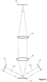
- FIG. 5 shows an example of a practical design of an optical objective head for an interferometer according to the present invention.
- the figure shows a microscope objective 16 looking down on the object 12, and the three illumination light beams 11A, 11B and 11C for in-plane measurements are coming down onto the object 12.
- Illumination light beam 11B which is common for X- and Y-measurements, is now the one which comes from behind.
- Illumination light beam 11C is to the left, and illumination light beam 11A is to the right in Figure 5 .
- the illumination light beams 11A-C can have different angles of incidence toward the object 12, but most convenient is that illumination light beams 11A and 11C are opposite to each other, as seen from the above projection ( Figure 4 ), while illumination light beam 11B is perpendicular to illumination light beams 11A and 11C in the projection seen from the above (seen with the Z-axis as observation direction as shown in Figure 4 ).
- the angle of incidence between the different illumination light beams 11A-C and the XY-plane may be selected to any value from close to zero degrees and up to close to ninety degrees. It will be most convenient to select the same angle between the three illumination light beams 11A-C and the XY-plane, for instance forty-five degrees or thirty degrees.
- the illumination light beams 11A, 11B and 11C can be collimated, or they can also be focussed to an imaginary point below or above the object surface, or the illumination light beams 11A-C can also be converging from (an imaginary) point in, or above, the illumination source.
- the illumination light beams 11A-C can go through diffusor plates 14, as shown for two of the illumination light beams 11A and 11C in Figure 2 . If a diffusor plate 14 is used in the illumination as shown in Figure 2 , this diffusor plate 14 can be movable with a translational and/or rotational movement, to change the speckle pattern in the light wave obtained when the light wave has passed the diffusor plate 14.
- speckle averaging To obtain so called speckle averaging, several exposures on a detector array 15 can be averaged, where the speckle pattern is changed between the exposures.
- the object 12 is illuminated by a single beam, preferably in the Z-direction.
- the illumination is done, by means of an illumination light beam 30A, through an imaging objective lens 16, which can typically be a microscope objective.
- the illumination light is reflected from a cube or plate beam splitter 17, which can preferably be a polarizing beam splitter.
- the light is reflected towards the objective lens 16 and goes through a retarder plate or quarter plate 18 and through the lens 16 and onto the object surface.
- Light reflected from the object surface goes back through the objective lens 16 and through the retarder plate or quarter plate 18 and through the (polarizing) beam splitter 17 and this light is focused on the detector array 15 by a second lens 19.
- the lens 16 can be arranged to focus the object image directly only the detector array 15, so that the second lens 19 can be omitted.
- the beam splitter 17 is a polarizing beam splitter
- a linear polarizer 20 should preferably be used before the illumination light comes to the polarizing beam splitter 17, as shown in Figure 6 .
- the illumination light 30A can also go through a diffusor plate 14 before it comes to the beam splitter 17, as shown in Figure 6 . If a diffusor plate 14 is used in the illumination, as shown in Figure 6 , this diffusor plate 14 can be moved by a translational and/or rotational movement, to change the speckle pattern in the illumination light wave obtained when the illumination light wave has passed the diffusor plate 14. To obtain so-called speckle averaging, several exposures on the detector array 15 can be averaged, where the speckle pattern is changed between exposures.
- the interferometric setup can be as shown in Figure 7 , where the optical configuration for both in-plane measurements and out-of-plane measurements are combined in the same interferometer. Only two of the three in-plane beams are shown in Figure 7 .
- the excitation of the object 12 is preferably controlled by a control unit, preferably by use of a signal generator.
- the control unit can also be arranged to change phase in the illumination light waves in at least two of five illumination light waves used for a full three-dimensional recording. This phase change can be dynamic, with a frequency equal to, or close to, the excitation frequency for the object 12.
- the phase change can also be performed in steps, to be used with so-called phase stepping algorithms.
- the control unit should be able to supply dynamic and stepwise phase shifts simultaneously.
- two illumination light beams 11A-C, 30A-B are used for each measurements.
- the dynamic and stepwise phase shifts can be applied to one and the same illumination light beam 11A-C, 30A-B being used for each measurement, or the dynamic phase shift can be applied to one of the in-plane illumination light beams 11A-C or out-of-plane illumination light beams 30A-B while the stepwise phase shift can be applied to the other in-plane illumination light beam 11A-C or out-of-plane illumination light beam 30A-B.
- illumination light beam 11B in Figures 3-5 which is common for X- and Y-measurements, is preferably used for dynamic phase shift.
- any of the two light beams 30A-B involved can be used for dynamic and/or stepwise phase shift.
- the control unit controls the excitation of the object 12 and the phase shifts in the beams 11A-C, 30A-B.
- the present invention makes use of an algorithm where several detector array exposures (images) are acquired while the control unit controls and changes parameters like:
- the data acquired by the control unit is then being used to calculate the amplitude and phase of the object vibrations.
- the measuring principle can be based on the use of multiple recordings with different intensities in the detector image of the object 12, and where the control unit uses a spatial selection algorithm to select signals from different recordings for different points or areas. This means that some points or areas on the imaged surface are using results from one recording or exposure, while other points or areas are using results from other recordings or exposures.
- control unit can combine the three results to find the full three-dimensional vibration mode or vibration map for the object at the measured frequency.
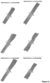
- the control unit can display this as animated plots like indicated in Figure 8 .
- figure 8 six plots of the full three-dimensional object movement are shown, for different vibration phases.
- the control unit can create many plots like this, for instance thirty plots differentiated by twelve degrees with respect to a full 360 degrees vibration period, to show an animated display of the three-dimensional object vibration.
- the invention can also be used the same way, but for vibration recordings in two dimensions, for instance in-plane vibrations in the X- and Y- directions.
- control unit is provided with means and/or software for one or more of the following:
Landscapes
- Physics & Mathematics (AREA)
- General Physics & Mathematics (AREA)
- Spectroscopy & Molecular Physics (AREA)
- Length Measuring Devices By Optical Means (AREA)
- Instruments For Measurement Of Length By Optical Means (AREA)
- Measurement Of Mechanical Vibrations Or Ultrasonic Waves (AREA)
- Investigating Or Analyzing Materials By The Use Of Ultrasonic Waves (AREA)
Applications Claiming Priority (2)
| Application Number | Priority Date | Filing Date | Title |
|---|---|---|---|
| NO20121458A NO334730B1 (no) | 2012-12-05 | 2012-12-05 | Fremgangsmåte for vibrasjonsmåling og interferometer |
| PCT/NO2013/050214 WO2014088424A1 (en) | 2012-12-05 | 2013-12-04 | Method of vibration measurement and interferometer |
Publications (4)
| Publication Number | Publication Date |
|---|---|
| EP2929305A1 EP2929305A1 (en) | 2015-10-14 |
| EP2929305A4 EP2929305A4 (en) | 2016-07-20 |
| EP2929305C0 EP2929305C0 (en) | 2024-01-31 |
| EP2929305B1 true EP2929305B1 (en) | 2024-01-31 |
Family
ID=50883743
Family Applications (1)
| Application Number | Title | Priority Date | Filing Date |
|---|---|---|---|
| EP13860879.9A Active EP2929305B1 (en) | 2012-12-05 | 2013-12-04 | Method of vibration measurement and interferometer |
Country Status (6)
| Country | Link |
|---|---|
| US (1) | US9964432B2 (enExample) |
| EP (1) | EP2929305B1 (enExample) |
| JP (1) | JP6307517B2 (enExample) |
| CN (1) | CN104823029B (enExample) |
| NO (1) | NO334730B1 (enExample) |
| WO (1) | WO2014088424A1 (enExample) |
Families Citing this family (5)
| Publication number | Priority date | Publication date | Assignee | Title |
|---|---|---|---|---|
| GB2544727A (en) * | 2015-11-16 | 2017-05-31 | Optonor As | Optical interferometry |
| GB2570742B (en) | 2018-06-01 | 2020-10-28 | Optonor As | Optical-interference analysis |
| EP3757445A1 (en) | 2019-06-24 | 2020-12-30 | Hexagon Ragasco AS | System and method for testing composite pressure vessels |
| NO20200190A1 (en) | 2020-02-14 | 2021-08-16 | Optonor As | System and method for analysing an object |
| JPWO2023120170A1 (enExample) * | 2021-12-22 | 2023-06-29 |
Family Cites Families (11)
| Publication number | Priority date | Publication date | Assignee | Title |
|---|---|---|---|---|
| US5229832A (en) * | 1991-07-08 | 1993-07-20 | Industrial Quality, Inc. | Optical ultrasonic material characterization apparatus and method |
| AU6036599A (en) * | 1998-09-09 | 2000-03-27 | Lockheed Martin Idaho Technologies Company | Method and apparatus for assessing material properties of sheet-like materials |
| NO314323B1 (no) | 2000-03-24 | 2003-03-03 | Optonor As | Framgangsmåte og interferometer for måling av mikroskopisk vibrasjon |
| JP3955899B2 (ja) * | 2002-09-20 | 2007-08-08 | 国立大学法人埼玉大学 | 電子的スペックル干渉法を用いた変形計測方法および装置 |
| WO2005062941A2 (en) * | 2003-12-22 | 2005-07-14 | Bossa Nova Technologies, Llc | Multi-channel laser interferometric method and apparatus for detection of ultrasonic motion from a surface |
| GB2411001B (en) * | 2004-02-10 | 2007-03-28 | Statoil Asa | Seismic exploration |
| GB2416835C (en) * | 2004-08-04 | 2013-11-06 | Statoil Asa | Method and apparatus for studying surfaces |
| CN100362316C (zh) * | 2006-03-08 | 2008-01-16 | 中国船舶重工集团公司第七一一研究所 | 一种三维电子散斑干涉仪 |
| DE102007023826A1 (de) * | 2007-05-21 | 2008-11-27 | Polytec Gmbh | Verfahren und Vorrichtung zur berührungslosen Schwingungsmessung |
| NL1036179A1 (nl) * | 2007-11-20 | 2009-05-25 | Asml Netherlands Bv | Lithographic apparatus and method. |
| GB0803701D0 (en) * | 2008-02-28 | 2008-04-09 | Statoilhydro Asa | Improved interferometric methods and apparatus for seismic exploration |
-
2012
- 2012-12-05 NO NO20121458A patent/NO334730B1/no unknown
-
2013
- 2013-12-04 EP EP13860879.9A patent/EP2929305B1/en active Active
- 2013-12-04 JP JP2015546414A patent/JP6307517B2/ja active Active
- 2013-12-04 WO PCT/NO2013/050214 patent/WO2014088424A1/en not_active Ceased
- 2013-12-04 CN CN201380063341.7A patent/CN104823029B/zh active Active
- 2013-12-04 US US14/648,378 patent/US9964432B2/en active Active
Also Published As
| Publication number | Publication date |
|---|---|
| EP2929305C0 (en) | 2024-01-31 |
| NO20121458A1 (no) | 2014-05-19 |
| US9964432B2 (en) | 2018-05-08 |
| JP6307517B2 (ja) | 2018-04-04 |
| CN104823029A (zh) | 2015-08-05 |
| CN104823029B (zh) | 2018-09-04 |
| EP2929305A1 (en) | 2015-10-14 |
| NO334730B1 (no) | 2014-05-19 |
| JP2016501373A (ja) | 2016-01-18 |
| US20150308887A1 (en) | 2015-10-29 |
| EP2929305A4 (en) | 2016-07-20 |
| WO2014088424A1 (en) | 2014-06-12 |
Similar Documents
| Publication | Publication Date | Title |
|---|---|---|
| EP2929305B1 (en) | Method of vibration measurement and interferometer | |
| CN108106556B (zh) | 基于数字散斑干涉的曲面物体离面形变测量方法及装置 | |
| CN114502912A (zh) | 混合式3d检验系统 | |
| JP2007512541A (ja) | 三次元分光的符号化撮像のための方法と装置 | |
| KR20050114611A (ko) | 간섭계에서 대상에 의해 반사/산란되고 투과되는 빔의 공액직교 필드의 공동 측정 장치 및 방법 | |
| CN108562241B (zh) | 基于光纤束的数字全息柔性测量的装置与方法 | |
| CN110095085A (zh) | 一种实时相移共光路干涉显微装置和方法 | |
| EP3635328A1 (en) | Methods and systems of holographic interferometry | |
| JP5354675B2 (ja) | 変位分布計測方法、装置及びプログラム | |
| US6433876B1 (en) | Multiple wavelength or multiple shear distance quantitative differential interference contrast microscopy | |
| JP2003529063A (ja) | 振動測定方法及び干渉計 | |
| EP2535679A1 (en) | Improvements in or relating to interferometry | |
| Abdelsalam et al. | Interferometry and its applications in surface metrology | |
| JP2003222508A (ja) | 表面形状測定装置及び表面形状測定方法 | |
| Harizanova et al. | Three-dimensional profilometry by symmetrical fringes projection technique | |
| CN107167071A (zh) | 基于消偏振分光棱镜的同步相移干涉测量装置 | |
| Chen et al. | Microscopic fringe projection system and measuring method | |
| JP2014010019A (ja) | 干渉計測装置 | |
| Sivakumar et al. | Measurement of surface profile in vibrating environment with instantaneous phase shifting interferometry | |
| GB2433317A (en) | Phase shifting imaging module for handheld interferometer | |
| Doval et al. | Measuring amplitude and phase of vibration with double-exposure stroboscopic TV Holography | |
| Wu et al. | Simultaneous three-dimensional deformation measuring based on a simple phase-shift device combination with tri-wavelength and three-CCD camera | |
| Stašík et al. | Advanced measurement procedure for interferometric microscope for three-dimensional imaging of complex surfaces using two-wavelength interferometry and reference arm attenuation | |
| Ellingsrud et al. | Torsional dynamics of the Birnboim-Schrag multiple lump resonator studied using TV-holography | |
| Jackson et al. | Demonstration of Interference Pattern Structured Illumination Imaging |
Legal Events
| Date | Code | Title | Description |
|---|---|---|---|
| PUAI | Public reference made under article 153(3) epc to a published international application that has entered the european phase |
Free format text: ORIGINAL CODE: 0009012 |
|
| 17P | Request for examination filed |
Effective date: 20150616 |
|
| AK | Designated contracting states |
Kind code of ref document: A1 Designated state(s): AL AT BE BG CH CY CZ DE DK EE ES FI FR GB GR HR HU IE IS IT LI LT LU LV MC MK MT NL NO PL PT RO RS SE SI SK SM TR |
|
| AX | Request for extension of the european patent |
Extension state: BA ME |
|
| DAX | Request for extension of the european patent (deleted) | ||
| RA4 | Supplementary search report drawn up and despatched (corrected) |
Effective date: 20160620 |
|
| RIC1 | Information provided on ipc code assigned before grant |
Ipc: G01H 1/00 20060101ALI20160614BHEP Ipc: G01H 9/00 20060101AFI20160614BHEP Ipc: G01B 9/02 20060101ALI20160614BHEP |
|
| STAA | Information on the status of an ep patent application or granted ep patent |
Free format text: STATUS: EXAMINATION IS IN PROGRESS |
|
| 17Q | First examination report despatched |
Effective date: 20210419 |
|
| GRAP | Despatch of communication of intention to grant a patent |
Free format text: ORIGINAL CODE: EPIDOSNIGR1 |
|
| STAA | Information on the status of an ep patent application or granted ep patent |
Free format text: STATUS: GRANT OF PATENT IS INTENDED |
|
| RIC1 | Information provided on ipc code assigned before grant |
Ipc: G01H 9/00 20060101AFI20230522BHEP |
|
| P01 | Opt-out of the competence of the unified patent court (upc) registered |
Effective date: 20230526 |
|
| INTG | Intention to grant announced |
Effective date: 20230622 |
|
| GRAS | Grant fee paid |
Free format text: ORIGINAL CODE: EPIDOSNIGR3 |
|
| RAP3 | Party data changed (applicant data changed or rights of an application transferred) |
Owner name: OPTONOR AS |
|
| GRAA | (expected) grant |
Free format text: ORIGINAL CODE: 0009210 |
|
| STAA | Information on the status of an ep patent application or granted ep patent |
Free format text: STATUS: THE PATENT HAS BEEN GRANTED |
|
| AK | Designated contracting states |
Kind code of ref document: B1 Designated state(s): AL AT BE BG CH CY CZ DE DK EE ES FI FR GB GR HR HU IE IS IT LI LT LU LV MC MK MT NL NO PL PT RO RS SE SI SK SM TR |
|
| REG | Reference to a national code |
Ref country code: GB Ref legal event code: FG4D Ref country code: CH Ref legal event code: EP |
|
| REG | Reference to a national code |
Ref country code: DE Ref legal event code: R096 Ref document number: 602013085251 Country of ref document: DE |
|
| REG | Reference to a national code |
Ref country code: IE Ref legal event code: FG4D |
|
| U01 | Request for unitary effect filed |
Effective date: 20240226 |
|
| U07 | Unitary effect registered |
Designated state(s): AT BE BG DE DK EE FI FR IT LT LU LV MT NL PT SE SI Effective date: 20240304 |
|
| P04 | Withdrawal of opt-out of the competence of the unified patent court (upc) registered |
Effective date: 20240412 |
|
| REG | Reference to a national code |
Ref country code: LT Ref legal event code: MG9D |
|
| PG25 | Lapsed in a contracting state [announced via postgrant information from national office to epo] |
Ref country code: IS Free format text: LAPSE BECAUSE OF FAILURE TO SUBMIT A TRANSLATION OF THE DESCRIPTION OR TO PAY THE FEE WITHIN THE PRESCRIBED TIME-LIMIT Effective date: 20240531 |
|
| PG25 | Lapsed in a contracting state [announced via postgrant information from national office to epo] |
Ref country code: GR Free format text: LAPSE BECAUSE OF FAILURE TO SUBMIT A TRANSLATION OF THE DESCRIPTION OR TO PAY THE FEE WITHIN THE PRESCRIBED TIME-LIMIT Effective date: 20240501 |
|
| PG25 | Lapsed in a contracting state [announced via postgrant information from national office to epo] |
Ref country code: RS Free format text: LAPSE BECAUSE OF FAILURE TO SUBMIT A TRANSLATION OF THE DESCRIPTION OR TO PAY THE FEE WITHIN THE PRESCRIBED TIME-LIMIT Effective date: 20240430 Ref country code: HR Free format text: LAPSE BECAUSE OF FAILURE TO SUBMIT A TRANSLATION OF THE DESCRIPTION OR TO PAY THE FEE WITHIN THE PRESCRIBED TIME-LIMIT Effective date: 20240131 |
|
| PG25 | Lapsed in a contracting state [announced via postgrant information from national office to epo] |
Ref country code: ES Free format text: LAPSE BECAUSE OF FAILURE TO SUBMIT A TRANSLATION OF THE DESCRIPTION OR TO PAY THE FEE WITHIN THE PRESCRIBED TIME-LIMIT Effective date: 20240131 |
|
| PG25 | Lapsed in a contracting state [announced via postgrant information from national office to epo] |
Ref country code: RS Free format text: LAPSE BECAUSE OF FAILURE TO SUBMIT A TRANSLATION OF THE DESCRIPTION OR TO PAY THE FEE WITHIN THE PRESCRIBED TIME-LIMIT Effective date: 20240430 Ref country code: NO Free format text: LAPSE BECAUSE OF FAILURE TO SUBMIT A TRANSLATION OF THE DESCRIPTION OR TO PAY THE FEE WITHIN THE PRESCRIBED TIME-LIMIT Effective date: 20240430 Ref country code: IS Free format text: LAPSE BECAUSE OF FAILURE TO SUBMIT A TRANSLATION OF THE DESCRIPTION OR TO PAY THE FEE WITHIN THE PRESCRIBED TIME-LIMIT Effective date: 20240531 Ref country code: HR Free format text: LAPSE BECAUSE OF FAILURE TO SUBMIT A TRANSLATION OF THE DESCRIPTION OR TO PAY THE FEE WITHIN THE PRESCRIBED TIME-LIMIT Effective date: 20240131 Ref country code: GR Free format text: LAPSE BECAUSE OF FAILURE TO SUBMIT A TRANSLATION OF THE DESCRIPTION OR TO PAY THE FEE WITHIN THE PRESCRIBED TIME-LIMIT Effective date: 20240501 Ref country code: ES Free format text: LAPSE BECAUSE OF FAILURE TO SUBMIT A TRANSLATION OF THE DESCRIPTION OR TO PAY THE FEE WITHIN THE PRESCRIBED TIME-LIMIT Effective date: 20240131 |
|
| PG25 | Lapsed in a contracting state [announced via postgrant information from national office to epo] |
Ref country code: PL Free format text: LAPSE BECAUSE OF FAILURE TO SUBMIT A TRANSLATION OF THE DESCRIPTION OR TO PAY THE FEE WITHIN THE PRESCRIBED TIME-LIMIT Effective date: 20240131 |
|
| PG25 | Lapsed in a contracting state [announced via postgrant information from national office to epo] |
Ref country code: PL Free format text: LAPSE BECAUSE OF FAILURE TO SUBMIT A TRANSLATION OF THE DESCRIPTION OR TO PAY THE FEE WITHIN THE PRESCRIBED TIME-LIMIT Effective date: 20240131 |
|
| PG25 | Lapsed in a contracting state [announced via postgrant information from national office to epo] |
Ref country code: SM Free format text: LAPSE BECAUSE OF FAILURE TO SUBMIT A TRANSLATION OF THE DESCRIPTION OR TO PAY THE FEE WITHIN THE PRESCRIBED TIME-LIMIT Effective date: 20240131 |
|
| PG25 | Lapsed in a contracting state [announced via postgrant information from national office to epo] |
Ref country code: CZ Free format text: LAPSE BECAUSE OF FAILURE TO SUBMIT A TRANSLATION OF THE DESCRIPTION OR TO PAY THE FEE WITHIN THE PRESCRIBED TIME-LIMIT Effective date: 20240131 |
|
| PG25 | Lapsed in a contracting state [announced via postgrant information from national office to epo] |
Ref country code: SK Free format text: LAPSE BECAUSE OF FAILURE TO SUBMIT A TRANSLATION OF THE DESCRIPTION OR TO PAY THE FEE WITHIN THE PRESCRIBED TIME-LIMIT Effective date: 20240131 |
|
| PG25 | Lapsed in a contracting state [announced via postgrant information from national office to epo] |
Ref country code: SM Free format text: LAPSE BECAUSE OF FAILURE TO SUBMIT A TRANSLATION OF THE DESCRIPTION OR TO PAY THE FEE WITHIN THE PRESCRIBED TIME-LIMIT Effective date: 20240131 Ref country code: SK Free format text: LAPSE BECAUSE OF FAILURE TO SUBMIT A TRANSLATION OF THE DESCRIPTION OR TO PAY THE FEE WITHIN THE PRESCRIBED TIME-LIMIT Effective date: 20240131 Ref country code: RO Free format text: LAPSE BECAUSE OF FAILURE TO SUBMIT A TRANSLATION OF THE DESCRIPTION OR TO PAY THE FEE WITHIN THE PRESCRIBED TIME-LIMIT Effective date: 20240131 Ref country code: CZ Free format text: LAPSE BECAUSE OF FAILURE TO SUBMIT A TRANSLATION OF THE DESCRIPTION OR TO PAY THE FEE WITHIN THE PRESCRIBED TIME-LIMIT Effective date: 20240131 |
|
| REG | Reference to a national code |
Ref country code: DE Ref legal event code: R097 Ref document number: 602013085251 Country of ref document: DE |
|
| PLBE | No opposition filed within time limit |
Free format text: ORIGINAL CODE: 0009261 |
|
| STAA | Information on the status of an ep patent application or granted ep patent |
Free format text: STATUS: NO OPPOSITION FILED WITHIN TIME LIMIT |
|
| U20 | Renewal fee for the european patent with unitary effect paid |
Year of fee payment: 12 Effective date: 20241107 |
|
| 26N | No opposition filed |
Effective date: 20241101 |
|
| PG25 | Lapsed in a contracting state [announced via postgrant information from national office to epo] |
Ref country code: MC Free format text: LAPSE BECAUSE OF FAILURE TO SUBMIT A TRANSLATION OF THE DESCRIPTION OR TO PAY THE FEE WITHIN THE PRESCRIBED TIME-LIMIT Effective date: 20240131 |
|
| REG | Reference to a national code |
Ref country code: CH Ref legal event code: PL |
|
| GBPC | Gb: european patent ceased through non-payment of renewal fee |
Effective date: 20241204 |
|
| PG25 | Lapsed in a contracting state [announced via postgrant information from national office to epo] |
Ref country code: GB Free format text: LAPSE BECAUSE OF NON-PAYMENT OF DUE FEES Effective date: 20241204 |
|
| PG25 | Lapsed in a contracting state [announced via postgrant information from national office to epo] |
Ref country code: CH Free format text: LAPSE BECAUSE OF NON-PAYMENT OF DUE FEES Effective date: 20241231 |
|
| PG25 | Lapsed in a contracting state [announced via postgrant information from national office to epo] |
Ref country code: IE Free format text: LAPSE BECAUSE OF NON-PAYMENT OF DUE FEES Effective date: 20241204 |