EP2929167B1 - Verfahren zur bestimmung einer zylinderdruck-kurbelwellenpositions-zuordnung für eine brennkraftmaschine - Google Patents
Verfahren zur bestimmung einer zylinderdruck-kurbelwellenpositions-zuordnung für eine brennkraftmaschine Download PDFInfo
- Publication number
- EP2929167B1 EP2929167B1 EP13810912.9A EP13810912A EP2929167B1 EP 2929167 B1 EP2929167 B1 EP 2929167B1 EP 13810912 A EP13810912 A EP 13810912A EP 2929167 B1 EP2929167 B1 EP 2929167B1
- Authority
- EP
- European Patent Office
- Prior art keywords
- cylinder
- determining
- cylinder pressure
- curve
- internal combustion
- Prior art date
- Legal status (The legal status is an assumption and is not a legal conclusion. Google has not performed a legal analysis and makes no representation as to the accuracy of the status listed.)
- Not-in-force
Links
Images

Classifications
-
- F—MECHANICAL ENGINEERING; LIGHTING; HEATING; WEAPONS; BLASTING
- F02—COMBUSTION ENGINES; HOT-GAS OR COMBUSTION-PRODUCT ENGINE PLANTS
- F02D—CONTROLLING COMBUSTION ENGINES
- F02D41/00—Electrical control of supply of combustible mixture or its constituents
- F02D41/009—Electrical control of supply of combustible mixture or its constituents using means for generating position or synchronisation signals
-
- F—MECHANICAL ENGINEERING; LIGHTING; HEATING; WEAPONS; BLASTING
- F02—COMBUSTION ENGINES; HOT-GAS OR COMBUSTION-PRODUCT ENGINE PLANTS
- F02D—CONTROLLING COMBUSTION ENGINES
- F02D35/00—Controlling engines, dependent on conditions exterior or interior to engines, not otherwise provided for
- F02D35/02—Controlling engines, dependent on conditions exterior or interior to engines, not otherwise provided for on interior conditions
- F02D35/023—Controlling engines, dependent on conditions exterior or interior to engines, not otherwise provided for on interior conditions by determining the cylinder pressure
-
- F—MECHANICAL ENGINEERING; LIGHTING; HEATING; WEAPONS; BLASTING
- F02—COMBUSTION ENGINES; HOT-GAS OR COMBUSTION-PRODUCT ENGINE PLANTS
- F02D—CONTROLLING COMBUSTION ENGINES
- F02D41/00—Electrical control of supply of combustible mixture or its constituents
- F02D41/24—Electrical control of supply of combustible mixture or its constituents characterised by the use of digital means
- F02D41/2406—Electrical control of supply of combustible mixture or its constituents characterised by the use of digital means using essentially read only memories
- F02D41/2409—Addressing techniques specially adapted therefor
- F02D41/2419—Non-linear variation along at least one coordinate
-
- F—MECHANICAL ENGINEERING; LIGHTING; HEATING; WEAPONS; BLASTING
- F02—COMBUSTION ENGINES; HOT-GAS OR COMBUSTION-PRODUCT ENGINE PLANTS
- F02D—CONTROLLING COMBUSTION ENGINES
- F02D41/00—Electrical control of supply of combustible mixture or its constituents
- F02D41/24—Electrical control of supply of combustible mixture or its constituents characterised by the use of digital means
- F02D41/26—Electrical control of supply of combustible mixture or its constituents characterised by the use of digital means using computer, e.g. microprocessor
- F02D41/28—Interface circuits
-
- G—PHYSICS
- G01—MEASURING; TESTING
- G01B—MEASURING LENGTH, THICKNESS OR SIMILAR LINEAR DIMENSIONS; MEASURING ANGLES; MEASURING AREAS; MEASURING IRREGULARITIES OF SURFACES OR CONTOURS
- G01B21/00—Measuring arrangements or details thereof, where the measuring technique is not covered by the other groups of this subclass, unspecified or not relevant
- G01B21/16—Measuring arrangements or details thereof, where the measuring technique is not covered by the other groups of this subclass, unspecified or not relevant for measuring distance of clearance between spaced objects
-
- G—PHYSICS
- G01—MEASURING; TESTING
- G01M—TESTING STATIC OR DYNAMIC BALANCE OF MACHINES OR STRUCTURES; TESTING OF STRUCTURES OR APPARATUS, NOT OTHERWISE PROVIDED FOR
- G01M15/00—Testing of engines
- G01M15/04—Testing internal-combustion engines
- G01M15/05—Testing internal-combustion engines by combined monitoring of two or more different engine parameters
-
- F—MECHANICAL ENGINEERING; LIGHTING; HEATING; WEAPONS; BLASTING
- F02—COMBUSTION ENGINES; HOT-GAS OR COMBUSTION-PRODUCT ENGINE PLANTS
- F02D—CONTROLLING COMBUSTION ENGINES
- F02D41/00—Electrical control of supply of combustible mixture or its constituents
- F02D41/24—Electrical control of supply of combustible mixture or its constituents characterised by the use of digital means
- F02D41/26—Electrical control of supply of combustible mixture or its constituents characterised by the use of digital means using computer, e.g. microprocessor
- F02D41/28—Interface circuits
- F02D2041/286—Interface circuits comprising means for signal processing
Definitions
- the invention relates to a method for determining a cylinder pressure crankshaft position assignment for an internal combustion engine.
- the invention is based on the object to provide a novel method for determining a cylinder pressure crankshaft position assignment for an internal combustion engine.
- This object is achieved by a method for determining a cylinder pressure crankshaft position assignment for an internal combustion engine according to claim 1.
- the method comprises: metrologically detecting the crankshaft angle; metrological detection of the cylinder pressure; Calculating a cylinder volume dependent on the crankshaft angle; Determining a curve for the logarithmic cylinder pressure over the logarithmic cylinder volume as a function of the crankshaft angle; Analyzing the curve and determining an offset value for the crankshaft angle to determine a time-accurate cylinder pressure crankshaft position mapping.
- the inventive method allows automatic determination of the cylinder pressure crankshaft position assignment for cylinders of an internal combustion engine with simple means and high accuracy.
- the method according to the invention can be carried out automatically in internal combustion engines, both in fired operation and in non-fired, towed operation of an internal combustion engine.
- the crankshaft angle and the cylinder pressure are detected metrologically.
- the cylinder volume is calculated from the crankshaft angle, wherein a curve for the logarithmic cylinder pressure over the logarithmic cylinder volume as a function of the crankshaft angle is determined from the calculated cylinder volume, the measured crankshaft angle and the measured cylinder pressure. This curve is analyzed and, depending on the analysis, an offset value for the crankshaft angle is determined for determining the chronologically accurate cylinder pressure crankshaft position allocation.
- the curve is analyzed in the area of a cylinder reversal point to determine the offset value.
- the curve can be analyzed in the region of a lower cylinder inversion point or in the region of an upper cylinder inversion point for determining the offset value.
- the analysis of the curve in the area of the cylinder inversion point is particularly advantageous.
- the present invention relates to a method for automatically determining a cylinder pressure crankshaft position assignment for the cylinders of an internal combustion engine.
- the inventive method is automatically carried out both in the fired operation of an internal combustion engine as well as non-fired, towed operation of an internal combustion engine.
- a crankshaft angle is continuously measured by means of a rotary encoder, for example. Furthermore, the cylinder pressure is automatically detected with the aid of a pressure sensor, in particular depending on the crankshaft angle. From the metrologically detected crankshaft angle, the cylinder volume of the respective cylinder of the internal combustion engine is determined.
- a curve is determined for the logarithmic cylinder pressure over the logarithmic cylinder volume as a function of the crankshaft angle.
- This curve is analyzed, wherein an offsetting value for the crankshaft angle for determining the chronologically exact cylinder pressure crankshaft position assignment is determined from the curve profile.
- the analysis of the curve preferably takes place in the region of a cylinder inversion point, namely either in the area of the lower cylinder inversion point or bottom dead center or in the region of the upper cylinder inversion point or top dead center of a cylinder piston movement the respective cylinder of the internal combustion engine.
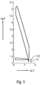
- FIG. 1 shows a highly schematic of a curve determined in the automatic execution of the method for the logarithmic cylinder pressure log p over the logarithmic cylinder volume log V as a function of the crankshaft angle, wherein FIG. 1 the logarithmic cylinder pressure log p is plotted against the logarithmic cylinder volume log V for two full revolutions of the crankshaft, ie over 720 ° of the crankshaft angle.
- the diagram of FIG. 1 Accordingly, the combustion process and a charge change in the respective cylinder of the internal combustion engine.
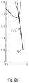
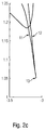
- FIGS. 2a . 2 B and 2c show different, alternative details of the diagram FIG. 1 in the region of the lower reversal point or bottom dead center of the cylinder piston movement of the respective cylinder.
- the course of the curve in the region of this reversing point 13 is analyzed, namely in such a way that, when in the area of the cylinder reversal point 13, an intersecting curve of the curve segments 11 and 12 is determined (see FIG Fig. 2b ) is closed to a delayed cylinder pressure signal in relation to the crankshaft angle signal, however, when in the area of the cylinder inversion point 13, a non-intersecting curve of the curve segments 11 and 12 is determined (see Figure 2c ), is closed to a postponed cylinder pressure signal in relation to the crankshaft angle signal.
- an area between the curve segments 11 and 12 of the curve in the area of the reversal point 13 is determined, wherein, depending on the area, the offset value for compensating the determined time shift between the cylinder pressure signal and the crankshaft angle signal is determined.
- the offset value is determined iteratively such that the area between the curve segments 11 and 12 of the curve in the region of the cylinder inversion point is minimal. This is for example in the diagram of FIG. 2a the case.
- the entire process can be performed continuously and automatically during the fired or towed operation of an internal combustion engine. In this way, an exact time assignment of the cylinder pressure to the crankshaft angle can be determined fully automatically during operation in order to control or regulate the operation of the internal combustion engine depending on this.
Landscapes
- Engineering & Computer Science (AREA)
- Combustion & Propulsion (AREA)
- Chemical & Material Sciences (AREA)
- Mechanical Engineering (AREA)
- General Engineering & Computer Science (AREA)
- Physics & Mathematics (AREA)
- General Physics & Mathematics (AREA)
- Microelectronics & Electronic Packaging (AREA)
- Nonlinear Science (AREA)
- Computer Hardware Design (AREA)
- Combined Controls Of Internal Combustion Engines (AREA)
- Electrical Control Of Air Or Fuel Supplied To Internal-Combustion Engine (AREA)
- Testing Of Engines (AREA)
Description
- Die Erfindung betrifft ein Verfahren zur Bestimmung einer Zylinderdruck-Kurbelwellenpositions-Zuordnung für eine Brennkraftmaschine.
- Zur Steuerung des Betriebs einer Brennkraftmaschine ist es von Vorteil, eine exakte zeitliche Zuordnung des Zylinderdrucks zur Kurbelwellenposition bzw. zum Kurbelwellenwinkel zu kennen. Bislang bereitet es Schwierigkeiten, eine solche Zylinderdruck-Kurbelwellenpositions-Zuordnung zu bestimmen.
- Der nächstliegende Stand der Technik wird in Dokument
US 2002/087256 A1 beschrieben. - Hievon ausgehend liegt der Erfindung die Aufgabe zu Grunde, ein neuartiges Verfahren zur Bestimmung einer Zylinderdruck-Kurbelwellenpositions-Zuordnung für eine Brennkraftmaschine zu schaffen.
- Diese Aufgabe wird durch ein Verfahren zur Bestimmung einer Zylinderdruck-Kurbelwellenpositions-Zuordnung für eine Brennkraftmaschine gemäß Anspruch 1 gelöst.
- Das Verfahren umfasst: messtechnisches Erfassen des Kurbelwellenwinkels; messtechnisches Erfassen des Zylinderdrucks; Berechnen eines Zylindervolumens abhängig vom Kurbelwellenwinkel; Ermittlung eines Kurvenverlaufs für den logarithmischen Zylinderdruck über dem logarithmischen Zylindervolumen in Abhängigkeit vom Kurbelwellenwinkel; Analysieren des Kurvenverlaufs und Ermittlung eines Offsetwerts für den Kurbelwellenwinkel zur Bestimmung einer zeitlich exakten Zylinderdruck-Kurbelwellenpositions-Zuordnung.
- Das erfindungsgemäße Verfahren erlaubt eine automatische Bestimmung der Zylinderdruck-Kurbelwellenpositions-Zuordnung für Zylinder einer Brennkraftmaschine mit einfachen Mitteln und hoher Genauigkeit. Das erfindungsgemäße Verfahren ist automatisch bei Brennkraftmaschinen durchführbar, und zwar sowohl bei im befeuerten Betrieb als auch bei im nicht befeuerten, geschleppten Betrieb einer Brennkraftmaschine. Erfindungsgemäß werden der Kurbelwellenwinkel und der Zylinderdruck messtechnisch erfasst. Aus dem Kurbelwellenwinkel wird das Zylindervolumen berechnet, wobei aus dem errechneten Zylindervolumen, dem gemessenen Kurbelwellenwinkel und dem gemessenen Zylinderdruck ein Kurvenverlauf für den logarithmischen Zylinderdruck über dem logarithmischen Zylindervolumen in Abhängigkeit vom Kurbelwellenwinkel ermittelt wird. Dieser Kurvenverlauf wird analysiert und abhängig von der Analyse ein Offsetwert für den Kurbelwellenwinkel zur Bestimmung der zeitlich exakten Zylinderdruck-Kurbelwellenpositions-Zuordnung ermittelt.
- Der Kurvenverlauf wird im Bereich eines Zylinderumkehrpunkts zur Ermittlung des Offsetwerts analysiert. Dabei kann der Kurvenverlauf im Bereich eines unteren Zylinderumkehrpunkts oder im Bereich eines oberen Zylinderumkehrpunkts zur Ermittlung des Offsetwerts analysiert werden. Die Analyse des Kurvenverlaufs im Bereich des Zylinderumkehrpunkts ist besonders vorteilhaft.
- Dann, wenn im Bereich des Zylinderumkehrpunkts ein sich schneidender Verlauf von Kurvensegmenten des Kurvenverlaufs ermittelt wird, wird auf ein nach spät verschobenes Zylinderdrucksignal im Verhältnis zum Kurbelwellenwinkelsignal geschlossen und ein Offsetwert zur Kompensation dieser Verschiebung abhängig von der Fläche zwischen den Kurvensegmenten des Kurvenverlaufs im Bereich des Zylinderumkehrpunkts ermittelt. Vorzugsweise kann hingegen dann, wenn im Bereich des Zylinderumkehrpunkts ein sich nicht schneidender Verlauf von Kurvensegmenten des Kurvenverlaufs ermittelt wird, auf ein nach früh verschobenes Zyljnderdrucksignal im Verhältnis zum Kurbelwellenwinkelsignal geschlossen werden und ein Offsetwert zur Kompensation dieser Verschiebung abhängig von der Fläche zwischen den Kurvensegmenten im Bereich des Zylinderumkehrpunkts ermittelt werden.
- Bevorzugte Weiterbildungen der Erfindung ergeben sich aus den Unteransprüchen und der nachfolgenden Beschreibung. Ausführungsbeispiele der Erfindung werden, ohne hierauf beschränkt zu sein, an Hand der Zeichnung näher erläutert. Dabei zeigt:
- Fig. 1:
- einen Kurvenverlauf zur Ermittlung eines Offsetwerts für den Kurbelwellenwinkel zur Bestimmung einer zeitlich exakten Zylinderdruck-Kurbelwellenpositions-Zuordnung, und
- Fig. 2a bis 2c:
- alternative Details des Kurvenverlaufs der
Fig. 1 . - Die vorliegende Erfindung betrifft ein Verfahren zur automatischen Bestimmung einer Zylinderdruck-Kurbelwellenpositions-Zuordnung für die Zylinder einer Brennkraftmaschine. Das erfindungsgemäße Verfahren ist sowohl im befeuerten Betrieb einer Brennkraftmaschine als auch nicht befeuerten, geschleppten Betrieb einer Brennkraftmaschine automatisch durchführbar.
- Zur automatischen Durchführung des erfindungsgemäßen Verfahrens wird beispielsweise mit Hilfe eines Drehgebers ein Kurbelwellenwinkel fortlaufend messtechnisch erfasst. Ferner wird mit Hilfe eines Drucksensors der Zylinderdruck automatisch erfasst, insbesondere abhängig vom Kurbelwellenwinkel. Aus dem messtechnisch erfassten Kurbelwellenwinkel wird das Zylindervolumen des jeweiligen Zylinders der Brennkraftmaschine bestimmt.
- Aus dem messtechnisch erfassten Zylinderdruck und aus dem aus dem messtechnisch erfassten Kurbelwellenwinkel berechneten Zylindervolumen wird ein Kurvenverlauf für den logarithmischen Zylinderdruck über dem logarithmischen Zylindervolumen in Abhängigkeit vom Kurbelwellenwinkel ermittelt.
- Dieser Kurvenverlauf wird analysiert, wobei aus dem Kurvenverlauf ein Offsetwert für den Kurbelwellenwinkel zur Bestimmung der zeitlich exakten Zylinderdruck-Kurbelwellenpositions-Zuordnung ermittelt wird.
- Die obigen Schritte des erfindungsgemäßen Verfahrens laufen vollautomatisch ab, wobei die Messwerte des Kurbelwellenwinkels und des Zylinderdrucks von den entsprechenden Sensoren einer Motorsteuerungseinrichtung bereitgestellt werden, die dann das Zylindervolumen berechnet und den Kurvenverlauf bestimmt und den Kurvenverlauf zur Ermittlung des Offsetwerts automatisch analysiert.
- Die Analyse des Kurvenverlaufs, nämlich des Kurvenverlaufs des logarithmischen Zylinderdrucks über dem logarithmischen Zylindervolumen in Abhängigkeit vom Kurbelwellenwinkel, erfolgt vorzugsweise im Bereich eines Zylinderumkehrpunkts, nämlich entweder im Bereich des unteren Zylinderumkehrpunkts bzw. unteren Totpunkts oder im Bereich des oberen Zylinderumkehrpunkts bzw. oberen Totpunkts einer Zylinderkolbenbewegung des jeweiligen Zylinders der Brennkraftmaschine.
-
Figur 1 zeigt stark schematisiert einen bei der automatischen Durchführung des Verfahrens ermittelten Kurvenverlauf für den logarithmischen Zylinderdruck log p über dem logarithmischen Zylindervolumen log V in Abhängigkeit vom Kurbelwellenwinkel, wobei inFigur 1 der logarithmische Zylinderdruck log p über dem logarithmischen Zylindervolumen log V für zwei volle Umdrehungen der Kurbelwelle aufgetragen ist, also über 720° des Kurbelwellenwinkels. Das Diagramm derFigur 1 umfasst demnach den Verbrennungsvorgang und einen Ladungswechsel im jeweiligen Zylinder der Brennkraftmaschine.Figuren 2a ,2b und2c zeigen unterschiedliche, alternative Details des Diagramms derFigur 1 im Bereich des unteren Umkehrpunkts bzw. unteren Totpunkts der Zylinderkolbenbewegung des jeweiligen Zylinders. - Im Bereich des unteren Umkehrpunkts bzw. unteren Totpunkts der Zylinderkolbenbewegung des jeweiligen Zylinder ist der Kurvenverlauf der
Figur 1 bzw. derFiguren 2a ,2b bzw. 2c durch spitz zusammenlaufende Kurvensegmente 11 und 12 gekennzeichnet, die an einem Punkt 13 spitz zusammenlaufen, der einen Wendepunkt im entsprechenden Kurvenverlauf darstellt. - Erfindungsgemäß wird nun der Kurvenverlauf im Bereich dieses Umkehrpunkts 13 analysiert, nämlich derart, dass dann, wenn im Bereich des Zylinderumkehrpunkts 13 ein sich schneidender Kurvenverlauf der Kurvensegmente 11 und 12 ermittelt wird (siehe
Fig. 2b ) auf ein nach spät verschobenes Zylinderdrucksignal im Verhältnis zum Kurbelwellenwinkelsignal geschlossen wird, hingegen dann, wenn im Bereich des Zylinderumkehrpunkts 13 ein sich nicht schneidender Kurvenverlauf der Kurvensegmente 11 und 12 ermittelt wird (sieheFigur 2c ), auf ein nach früh verschobenes Zylinderdrucksignal im Verhältnis zum Kurbelwellenwinkelsignal geschlossen wird. - Ferner wird eine Fläche zwischen den Kurvensegmenten 11 und 12 des Kurvenverlaufs im Bereich des Umkehrpunkts 13 ermittelt, wobei abhängig von der Fläche der Offsetwert zur Kompensation der festgestellten zeitlichen Verschiebung zwischen dem Zylinderdrucksignal und dem Kurbelwellenwinkelsignal ermittelt wird. Je größer diese Fläche ist, desto größer fällt der Offsetwert aus. Vorzugsweise wird der Offsetwert derart iterativ ermittelt, dass die Fläche zwischen den Kurvensegmenten 11 und 12 des Kurvenverlaufs im Bereich des Zylinderumkehrpunkts minimal ist. Dies ist zum Beispiel im Diagramm der
Figur 2a der Fall. - Das gesamte Verfahren kann kontinuierlich und automatisch während des befeuerten oder geschleppten Betriebs einer Brennkraftmaschine durchgeführt werden. So kann vollautomatisch im Betrieb eine exakte zeitliche Zuordnung des Zylinderdrucks zum Kurbelwellenwinkel ermittelt werden, um abhängig hiervon den Betrieb der Brennkraftmaschine zu steuern oder zu regeln.
Claims (6)
- Verfahren zur Bestimmung einer Zylinderdruck-Kurbelwellenpositions-Zuordnung für eine Brennkraftmaschine, mit folgenden Schritten:messtechnisches Erfassen des Kurbelwellenwinkels;messtechnisches Erfassen des Zylinderdrucks;Berechnen eines Zylindervolumens abhängig vom Kurbelwellenwinkel;Ermittlung eines Kurvenverlaufs für den logarithmischen Zylinderdruck über dem logarithmischen Zylindervolumen in Abhängigkeit vom Kurbelwellenwinkel;Analysieren des Kurvenverlaufs und Ermittlung eines Offsetwerts für den Kurbelwellenwinkel zur Bestimmung einer zeitlich exakten Zylinderdruck-Kurbelwellenpositions-Zuordnung,wobei der Kurvenverlauf im Bereich eines Zylinderumkehrpunkts zur Ermittlung des Offsetwerts analysiert wird,dadurch gekennzeichnet, dass dann, wenn im Bereich des Zylinderumkehrpunkts ein sich schneidender Verlauf von Kurvensegmenten des Kurvenverlaufs ermittelt wird, auf ein nach spät verschobenes Zylinderdrucksignal im Verhältnis zum Kurbelwellenwinkelsignal geschlossen und ein Offsetwert zur Kompensation dieser Verschiebung abhängig von der Fläche zwischen den Kurvensegmenten im Bereich des Zylinderumkehrpunkts ermittelt wird.
- Verfahren nach Anspruch 1, dadurch gekennzeichnet, dass die Bestimmung der Zylinderdruck-Kurbelwellenpositions-Zuordnung für die Brennkraftmaschine im befeuerten Betrieb der Brennkraftmaschine automatisch erfolgt.
- Verfahren nach Anspruch 1, dadurch gekennzeichnet, dass die Bestimmung der Zylinderdruck-Kurbelwellenpositions-Zuordnung für die Brennkraftmaschine im geschleppten Betrieb der Brennkraftmaschine automatisch erfolgt.
- Verfahren nach Anspruch 1, dadurch gekennzeichnet, dass der Kurvenverlauf im Bereich eines unteren Zylinderumkehrpunkts zur Ermittlung des Offsetwerts analysiert wird.
- Verfahren nach Anspruch 1, dadurch gekennzeichnet, dass der Kurvenverlauf im Bereich eines oberen Zylinderumkehrpunkts zur Ermittlung des Offsetwerts analysiert wird.
- Verfahren nach einem der Ansprüche 1 bis 5, dadurch gekennzeichnet, dass dann, wenn im Bereich des Zylinderumkehrpunkts ein sich nicht schneidender Verlauf von Kurvensegmenten des Kurvenverlaufs ermittelt wird, auf ein nach früh verschobenes Zylinderdrucksignal im Verhältnis zum Kurbelwellenwinkelsignal geschlossen und ein Offsetwert zur Kompensation dieser Verschiebung abhängig von der Fläche zwischen den Kurvensegmenten im Bereich des Zylinderumkehrpunkts ermittelt wird.
Applications Claiming Priority (2)
| Application Number | Priority Date | Filing Date | Title |
|---|---|---|---|
| DE102012023834.7A DE102012023834A1 (de) | 2012-12-06 | 2012-12-06 | Verfahren zur Bestimmung einer Zylinderdruck-Kurbelwellenpositions-Zuordnung für eine Brennkraftmaschine |
| PCT/EP2013/075811 WO2014086980A2 (de) | 2012-12-06 | 2013-12-06 | Verfahren zur bestimmung einer zylinderdruck-kurbelwellenpositions-zuordnung für eine brennkraftmaschine |
Publications (2)
| Publication Number | Publication Date |
|---|---|
| EP2929167A2 EP2929167A2 (de) | 2015-10-14 |
| EP2929167B1 true EP2929167B1 (de) | 2016-10-26 |
Family
ID=49816907
Family Applications (1)
| Application Number | Title | Priority Date | Filing Date |
|---|---|---|---|
| EP13810912.9A Not-in-force EP2929167B1 (de) | 2012-12-06 | 2013-12-06 | Verfahren zur bestimmung einer zylinderdruck-kurbelwellenpositions-zuordnung für eine brennkraftmaschine |
Country Status (7)
| Country | Link |
|---|---|
| US (1) | US20150308360A1 (de) |
| EP (1) | EP2929167B1 (de) |
| JP (1) | JP6030775B2 (de) |
| KR (1) | KR101738284B1 (de) |
| CN (1) | CN104822923B (de) |
| DE (1) | DE102012023834A1 (de) |
| WO (1) | WO2014086980A2 (de) |
Cited By (1)
| Publication number | Priority date | Publication date | Assignee | Title |
|---|---|---|---|---|
| US11280227B2 (en) | 2019-08-15 | 2022-03-22 | Volkswagen Aktiengesellschaft | Method for adaptation of a detected camshaft position, control unit for carrying out the method, internal combustion engine, and vehicle |
Families Citing this family (6)
| Publication number | Priority date | Publication date | Assignee | Title |
|---|---|---|---|---|
| DE202014004327U1 (de) * | 2014-05-24 | 2015-08-26 | GM Global Technology Operations LLC (n. d. Ges. d. Staates Delaware) | Mittel zum Ermitteln einer Zuordnung zwischen einer Kurbelwellenwinkelgröße und einer Kolbenstellungsgröße |
| US9689321B2 (en) * | 2015-06-10 | 2017-06-27 | GM Global Technology Operations LLC | Engine torque control with combustion phasing |
| WO2017042423A1 (en) * | 2015-09-11 | 2017-03-16 | Wärtsilä Finland Oy | A method of and a control system for determining an offset relating to crank angle measurement |
| JP6420915B2 (ja) * | 2015-10-27 | 2018-11-07 | 日立オートモティブシステムズ株式会社 | 内燃機関制御装置 |
| JP6281579B2 (ja) * | 2016-01-27 | 2018-02-21 | トヨタ自動車株式会社 | 内燃機関の制御装置 |
| GB2576025A (en) * | 2018-08-01 | 2020-02-05 | Comb Order Ltd | Synchronous real time dynamometer |
Family Cites Families (12)
| Publication number | Priority date | Publication date | Assignee | Title |
|---|---|---|---|---|
| CN1085630A (zh) * | 1992-10-13 | 1994-04-20 | 张弘 | 跟踪式点火控制系统 |
| DE4318504C2 (de) * | 1993-06-03 | 2001-03-29 | Siemens Ag | Verfahren zur Erzeugung eines Regelsignals für den Zündzeitpunkt einer Brennkraftmaschine |
| JPH0726966A (ja) * | 1993-07-07 | 1995-01-27 | Toyota Motor Corp | 吸気制御弁 |
| US6484694B2 (en) * | 2000-12-05 | 2002-11-26 | Detroit Diesel Corporation | Method of controlling an internal combustion engine |
| US6553305B2 (en) * | 2000-12-29 | 2003-04-22 | Visteon Global Technologies, Inc. | Real time adaptive engine position estimation |
| JP4281063B2 (ja) * | 2004-06-09 | 2009-06-17 | トヨタ自動車株式会社 | クランク角センサの補正装置および補正方法 |
| JP4367248B2 (ja) * | 2004-06-10 | 2009-11-18 | 株式会社デンソー | 内燃機関の制御装置 |
| US7454286B2 (en) * | 2006-12-20 | 2008-11-18 | Delphi Technologies, Inc. | Combustion control in an internal combustion engine |
| US7568467B2 (en) * | 2007-03-23 | 2009-08-04 | Gm Global Technology Operations, Inc. | Crank position correction using cylinder pressure |
| US7469576B2 (en) * | 2007-04-05 | 2008-12-30 | Delphi Technologies, Inc. | Method and apparatus for determining TDC for each cylinder of a multi-cylinder internal combustion engine |
| EP2481907B1 (de) * | 2009-09-24 | 2015-01-21 | Toyota Jidosha Kabushiki Kaisha | Steuerungsvorrichtung für einen verbrennungsmotor |
| JP5302173B2 (ja) * | 2009-12-07 | 2013-10-02 | 日立オートモティブシステムズ株式会社 | 内燃機関の可変動弁装置 |
-
2012
- 2012-12-06 DE DE102012023834.7A patent/DE102012023834A1/de not_active Withdrawn
-
2013
- 2013-12-06 EP EP13810912.9A patent/EP2929167B1/de not_active Not-in-force
- 2013-12-06 WO PCT/EP2013/075811 patent/WO2014086980A2/de not_active Ceased
- 2013-12-06 CN CN201380063855.2A patent/CN104822923B/zh not_active Expired - Fee Related
- 2013-12-06 JP JP2015546032A patent/JP6030775B2/ja not_active Expired - Fee Related
- 2013-12-06 US US14/649,499 patent/US20150308360A1/en not_active Abandoned
- 2013-12-06 KR KR1020157017510A patent/KR101738284B1/ko not_active Expired - Fee Related
Cited By (1)
| Publication number | Priority date | Publication date | Assignee | Title |
|---|---|---|---|---|
| US11280227B2 (en) | 2019-08-15 | 2022-03-22 | Volkswagen Aktiengesellschaft | Method for adaptation of a detected camshaft position, control unit for carrying out the method, internal combustion engine, and vehicle |
Also Published As
| Publication number | Publication date |
|---|---|
| KR101738284B1 (ko) | 2017-05-19 |
| EP2929167A2 (de) | 2015-10-14 |
| DE102012023834A1 (de) | 2014-06-12 |
| JP6030775B2 (ja) | 2016-11-24 |
| WO2014086980A3 (de) | 2014-10-16 |
| WO2014086980A2 (de) | 2014-06-12 |
| JP2015536417A (ja) | 2015-12-21 |
| KR20150088894A (ko) | 2015-08-03 |
| US20150308360A1 (en) | 2015-10-29 |
| CN104822923B (zh) | 2017-08-08 |
| CN104822923A (zh) | 2015-08-05 |
Similar Documents
| Publication | Publication Date | Title |
|---|---|---|
| WO2014086980A2 (de) | Verfahren zur bestimmung einer zylinderdruck-kurbelwellenpositions-zuordnung für eine brennkraftmaschine | |
| EP0474652B1 (de) | Verfahren zum messen von laufunruhe bei einer brennkraftmaschine und anwendung der verfahren | |
| DE102008053132B4 (de) | Steuerapparat für einen Verbrennungsmotor | |
| EP0474711B1 (de) | Verfahren zum bestimmen der verbrennungsluftmasse in den zylindern einer brennkraftmaschine | |
| EP3786436B1 (de) | Verfahren zur diagnostik von verbrennungsaussetzern einer verbrennungskraftmaschine | |
| WO1997011345A1 (de) | Verfahren zur verbrennungsaussetzererkennung durch auswertung von drehzahlschwankungen | |
| EP0076265B1 (de) | Verfahren und vorrichtung zum erkennen irregulärer verbrennungsvorgänge in einer brennkraftmaschine | |
| DE4215581B4 (de) | System zur Steuerung einer magnetventilgesteuerten Kraftstoffzumeßeinrichtung | |
| DE102013207173A1 (de) | Verfahren zur Bestimmung von Segmentzeiten eines Geberrads eines Verbrennungsmotors | |
| DE102008001307A1 (de) | Verfahren zur Ermittlung der Zündwilligkeit eines Kraftstoffs | |
| DE102006033062A1 (de) | Verfahren und Vorrichtung zur Ermittlung eines momentanen Verdichtungsverhältnisses einer Hubkolbenmaschine im Betrieb | |
| DE102009035700B3 (de) | Verfahren und Vorrichtung zur zylinderselektiven Erkennung von Zündaussetzern | |
| DE3917905A1 (de) | Verfahren zum optimieren des betriebs einer fremdgezuendeten kolbenbrennkraftmaschine, insbesondere eines otto-motors | |
| DE102005029137B3 (de) | Verfahren und Steuergerät zur Diagnose eines Gaswechsel-Ventilhub-Verstellsystems eines Verbrennungsmotors | |
| DE10113194A1 (de) | Verfahren und Vorrichtung zum Erkennen des Arbeitstaktes eines Zylinders eines Verbrennungsmotors | |
| WO2013131682A1 (de) | Drehzahlbasierte schätzung der frischluftfüllung des zylinders in einem einzylinderverbrennungsmotor | |
| DE10028885B4 (de) | Verfahren und Vorrichtung zum Erfassen des in einem Brennraum einer Brennkraftmaschine auftretenden Brennraumdrucks | |
| AT520079B1 (de) | Hubkolbenmaschine sowie Verfahren und Vorrichtung zur Diagnose und/oder Steuerung einer Hubkolbenmaschine | |
| DE102008044305B4 (de) | Verfahren, Steuergerät und Computerprogrammprodukt zur Erfassung der Laufunruhe eines mehrzylindrigen Verbrennungsmotors | |
| DE102004051908A1 (de) | Verfahren zur Ermittlung eines Brennraumdrucks | |
| AT518694B1 (de) | Hubkolbenmaschine sowie Verfahren und Vorrichtung zur Diagnose und/oder Steuerung einer Hubkolbenmaschine | |
| EP3470653A1 (de) | Verfahren zum erkennen von kompressionsverlusten von zylindern einer mehrzylindrigen brennkraftmaschine | |
| DE102012203559B4 (de) | Verfahren und Vorrichtung zum Betreiben einer Brennkraftmaschine | |
| DE102004023589B4 (de) | Verfahren zur Erkennung einer Veränderung von Steuerzeiten von Gaswechselventilen von Zylindern eines Verbrennungsmotors | |
| DE102011005289B3 (de) | Verfahren zur Auswertung eines Messsignals |
Legal Events
| Date | Code | Title | Description |
|---|---|---|---|
| PUAI | Public reference made under article 153(3) epc to a published international application that has entered the european phase |
Free format text: ORIGINAL CODE: 0009012 |
|
| 17P | Request for examination filed |
Effective date: 20150702 |
|
| AK | Designated contracting states |
Kind code of ref document: A2 Designated state(s): AL AT BE BG CH CY CZ DE DK EE ES FI FR GB GR HR HU IE IS IT LI LT LU LV MC MK MT NL NO PL PT RO RS SE SI SK SM TR |
|
| AX | Request for extension of the european patent |
Extension state: BA ME |
|
| DAX | Request for extension of the european patent (deleted) | ||
| GRAP | Despatch of communication of intention to grant a patent |
Free format text: ORIGINAL CODE: EPIDOSNIGR1 |
|
| RIC1 | Information provided on ipc code assigned before grant |
Ipc: F02D 41/24 20060101ALI20160616BHEP Ipc: F02D 35/02 20060101AFI20160616BHEP Ipc: F02D 41/28 20060101ALI20160616BHEP Ipc: F02D 41/00 20060101ALI20160616BHEP |
|
| INTG | Intention to grant announced |
Effective date: 20160719 |
|
| GRAS | Grant fee paid |
Free format text: ORIGINAL CODE: EPIDOSNIGR3 |
|
| GRAA | (expected) grant |
Free format text: ORIGINAL CODE: 0009210 |
|
| AK | Designated contracting states |
Kind code of ref document: B1 Designated state(s): AL AT BE BG CH CY CZ DE DK EE ES FI FR GB GR HR HU IE IS IT LI LT LU LV MC MK MT NL NO PL PT RO RS SE SI SK SM TR |
|
| REG | Reference to a national code |
Ref country code: GB Ref legal event code: FG4D Free format text: NOT ENGLISH |
|
| REG | Reference to a national code |
Ref country code: CH Ref legal event code: EP Ref country code: CH Ref legal event code: NV Representative=s name: E. BLUM AND CO. AG PATENT- UND MARKENANWAELTE , CH |
|
| REG | Reference to a national code |
Ref country code: AT Ref legal event code: REF Ref document number: 840208 Country of ref document: AT Kind code of ref document: T Effective date: 20161115 |
|
| REG | Reference to a national code |
Ref country code: IE Ref legal event code: FG4D Free format text: LANGUAGE OF EP DOCUMENT: GERMAN |
|
| REG | Reference to a national code |
Ref country code: DE Ref legal event code: R096 Ref document number: 502013005129 Country of ref document: DE |
|
| REG | Reference to a national code |
Ref country code: LT Ref legal event code: MG4D |
|
| PG25 | Lapsed in a contracting state [announced via postgrant information from national office to epo] |
Ref country code: LV Free format text: LAPSE BECAUSE OF FAILURE TO SUBMIT A TRANSLATION OF THE DESCRIPTION OR TO PAY THE FEE WITHIN THE PRESCRIBED TIME-LIMIT Effective date: 20161026 |
|
| REG | Reference to a national code |
Ref country code: NL Ref legal event code: MP Effective date: 20161026 |
|
| REG | Reference to a national code |
Ref country code: NO Ref legal event code: T2 Effective date: 20161026 |
|
| PG25 | Lapsed in a contracting state [announced via postgrant information from national office to epo] |
Ref country code: LT Free format text: LAPSE BECAUSE OF FAILURE TO SUBMIT A TRANSLATION OF THE DESCRIPTION OR TO PAY THE FEE WITHIN THE PRESCRIBED TIME-LIMIT Effective date: 20161026 Ref country code: SE Free format text: LAPSE BECAUSE OF FAILURE TO SUBMIT A TRANSLATION OF THE DESCRIPTION OR TO PAY THE FEE WITHIN THE PRESCRIBED TIME-LIMIT Effective date: 20161026 Ref country code: GR Free format text: LAPSE BECAUSE OF FAILURE TO SUBMIT A TRANSLATION OF THE DESCRIPTION OR TO PAY THE FEE WITHIN THE PRESCRIBED TIME-LIMIT Effective date: 20170127 |
|
| PG25 | Lapsed in a contracting state [announced via postgrant information from national office to epo] |
Ref country code: IS Free format text: LAPSE BECAUSE OF FAILURE TO SUBMIT A TRANSLATION OF THE DESCRIPTION OR TO PAY THE FEE WITHIN THE PRESCRIBED TIME-LIMIT Effective date: 20170226 Ref country code: NL Free format text: LAPSE BECAUSE OF FAILURE TO SUBMIT A TRANSLATION OF THE DESCRIPTION OR TO PAY THE FEE WITHIN THE PRESCRIBED TIME-LIMIT Effective date: 20161026 Ref country code: BE Free format text: LAPSE BECAUSE OF NON-PAYMENT OF DUE FEES Effective date: 20161231 Ref country code: PL Free format text: LAPSE BECAUSE OF FAILURE TO SUBMIT A TRANSLATION OF THE DESCRIPTION OR TO PAY THE FEE WITHIN THE PRESCRIBED TIME-LIMIT Effective date: 20161026 Ref country code: ES Free format text: LAPSE BECAUSE OF FAILURE TO SUBMIT A TRANSLATION OF THE DESCRIPTION OR TO PAY THE FEE WITHIN THE PRESCRIBED TIME-LIMIT Effective date: 20161026 Ref country code: PT Free format text: LAPSE BECAUSE OF FAILURE TO SUBMIT A TRANSLATION OF THE DESCRIPTION OR TO PAY THE FEE WITHIN THE PRESCRIBED TIME-LIMIT Effective date: 20170227 Ref country code: HR Free format text: LAPSE BECAUSE OF FAILURE TO SUBMIT A TRANSLATION OF THE DESCRIPTION OR TO PAY THE FEE WITHIN THE PRESCRIBED TIME-LIMIT Effective date: 20161026 Ref country code: RS Free format text: LAPSE BECAUSE OF FAILURE TO SUBMIT A TRANSLATION OF THE DESCRIPTION OR TO PAY THE FEE WITHIN THE PRESCRIBED TIME-LIMIT Effective date: 20161026 |
|
| REG | Reference to a national code |
Ref country code: DE Ref legal event code: R097 Ref document number: 502013005129 Country of ref document: DE |
|
| PG25 | Lapsed in a contracting state [announced via postgrant information from national office to epo] |
Ref country code: EE Free format text: LAPSE BECAUSE OF FAILURE TO SUBMIT A TRANSLATION OF THE DESCRIPTION OR TO PAY THE FEE WITHIN THE PRESCRIBED TIME-LIMIT Effective date: 20161026 Ref country code: DK Free format text: LAPSE BECAUSE OF FAILURE TO SUBMIT A TRANSLATION OF THE DESCRIPTION OR TO PAY THE FEE WITHIN THE PRESCRIBED TIME-LIMIT Effective date: 20161026 Ref country code: CZ Free format text: LAPSE BECAUSE OF FAILURE TO SUBMIT A TRANSLATION OF THE DESCRIPTION OR TO PAY THE FEE WITHIN THE PRESCRIBED TIME-LIMIT Effective date: 20161026 Ref country code: RO Free format text: LAPSE BECAUSE OF FAILURE TO SUBMIT A TRANSLATION OF THE DESCRIPTION OR TO PAY THE FEE WITHIN THE PRESCRIBED TIME-LIMIT Effective date: 20161026 Ref country code: SK Free format text: LAPSE BECAUSE OF FAILURE TO SUBMIT A TRANSLATION OF THE DESCRIPTION OR TO PAY THE FEE WITHIN THE PRESCRIBED TIME-LIMIT Effective date: 20161026 |
|
| PG25 | Lapsed in a contracting state [announced via postgrant information from national office to epo] |
Ref country code: BG Free format text: LAPSE BECAUSE OF FAILURE TO SUBMIT A TRANSLATION OF THE DESCRIPTION OR TO PAY THE FEE WITHIN THE PRESCRIBED TIME-LIMIT Effective date: 20170126 Ref country code: SM Free format text: LAPSE BECAUSE OF FAILURE TO SUBMIT A TRANSLATION OF THE DESCRIPTION OR TO PAY THE FEE WITHIN THE PRESCRIBED TIME-LIMIT Effective date: 20161026 |
|
| PLBE | No opposition filed within time limit |
Free format text: ORIGINAL CODE: 0009261 |
|
| STAA | Information on the status of an ep patent application or granted ep patent |
Free format text: STATUS: NO OPPOSITION FILED WITHIN TIME LIMIT |
|
| PG25 | Lapsed in a contracting state [announced via postgrant information from national office to epo] |
Ref country code: MC Free format text: LAPSE BECAUSE OF FAILURE TO SUBMIT A TRANSLATION OF THE DESCRIPTION OR TO PAY THE FEE WITHIN THE PRESCRIBED TIME-LIMIT Effective date: 20161026 |
|
| REG | Reference to a national code |
Ref country code: FR Ref legal event code: ST Effective date: 20170831 |
|
| 26N | No opposition filed |
Effective date: 20170727 |
|
| REG | Reference to a national code |
Ref country code: IE Ref legal event code: MM4A |
|
| PG25 | Lapsed in a contracting state [announced via postgrant information from national office to epo] |
Ref country code: FR Free format text: LAPSE BECAUSE OF NON-PAYMENT OF DUE FEES Effective date: 20170102 Ref country code: LU Free format text: LAPSE BECAUSE OF NON-PAYMENT OF DUE FEES Effective date: 20161206 |
|
| PG25 | Lapsed in a contracting state [announced via postgrant information from national office to epo] |
Ref country code: IE Free format text: LAPSE BECAUSE OF NON-PAYMENT OF DUE FEES Effective date: 20161206 Ref country code: SI Free format text: LAPSE BECAUSE OF FAILURE TO SUBMIT A TRANSLATION OF THE DESCRIPTION OR TO PAY THE FEE WITHIN THE PRESCRIBED TIME-LIMIT Effective date: 20161026 |
|
| REG | Reference to a national code |
Ref country code: BE Ref legal event code: MM Effective date: 20161231 |
|
| PG25 | Lapsed in a contracting state [announced via postgrant information from national office to epo] |
Ref country code: HU Free format text: LAPSE BECAUSE OF FAILURE TO SUBMIT A TRANSLATION OF THE DESCRIPTION OR TO PAY THE FEE WITHIN THE PRESCRIBED TIME-LIMIT; INVALID AB INITIO Effective date: 20131206 |
|
| PG25 | Lapsed in a contracting state [announced via postgrant information from national office to epo] |
Ref country code: MK Free format text: LAPSE BECAUSE OF FAILURE TO SUBMIT A TRANSLATION OF THE DESCRIPTION OR TO PAY THE FEE WITHIN THE PRESCRIBED TIME-LIMIT Effective date: 20161026 Ref country code: CY Free format text: LAPSE BECAUSE OF FAILURE TO SUBMIT A TRANSLATION OF THE DESCRIPTION OR TO PAY THE FEE WITHIN THE PRESCRIBED TIME-LIMIT Effective date: 20161026 |
|
| REG | Reference to a national code |
Ref country code: CH Ref legal event code: PFA Owner name: MAN ENERGY SOLUTIONS SE, DE Free format text: FORMER OWNER: MAN DIESEL AND TURBO SE, DE |
|
| GBPC | Gb: european patent ceased through non-payment of renewal fee |
Effective date: 20171206 |
|
| PG25 | Lapsed in a contracting state [announced via postgrant information from national office to epo] |
Ref country code: MT Free format text: LAPSE BECAUSE OF FAILURE TO SUBMIT A TRANSLATION OF THE DESCRIPTION OR TO PAY THE FEE WITHIN THE PRESCRIBED TIME-LIMIT Effective date: 20161026 |
|
| PG25 | Lapsed in a contracting state [announced via postgrant information from national office to epo] |
Ref country code: TR Free format text: LAPSE BECAUSE OF FAILURE TO SUBMIT A TRANSLATION OF THE DESCRIPTION OR TO PAY THE FEE WITHIN THE PRESCRIBED TIME-LIMIT Effective date: 20161026 |
|
| PG25 | Lapsed in a contracting state [announced via postgrant information from national office to epo] |
Ref country code: GB Free format text: LAPSE BECAUSE OF NON-PAYMENT OF DUE FEES Effective date: 20171206 |
|
| REG | Reference to a national code |
Ref country code: NO Ref legal event code: CHAD Owner name: MAN ENERGY SOLUTIONS SE, DE |
|
| REG | Reference to a national code |
Ref country code: DE Ref legal event code: R081 Ref document number: 502013005129 Country of ref document: DE Owner name: MAN ENERGY SOLUTIONS SE, DE Free format text: FORMER OWNER: MAN DIESEL & TURBO SE, 86153 AUGSBURG, DE |
|
| PGFP | Annual fee paid to national office [announced via postgrant information from national office to epo] |
Ref country code: DE Payment date: 20191210 Year of fee payment: 7 Ref country code: FI Payment date: 20191220 Year of fee payment: 7 |
|
| REG | Reference to a national code |
Ref country code: AT Ref legal event code: MM01 Ref document number: 840208 Country of ref document: AT Kind code of ref document: T Effective date: 20181206 |
|
| PGFP | Annual fee paid to national office [announced via postgrant information from national office to epo] |
Ref country code: IT Payment date: 20191230 Year of fee payment: 7 |
|
| PGFP | Annual fee paid to national office [announced via postgrant information from national office to epo] |
Ref country code: CH Payment date: 20191219 Year of fee payment: 7 |
|
| PG25 | Lapsed in a contracting state [announced via postgrant information from national office to epo] |
Ref country code: AT Free format text: LAPSE BECAUSE OF NON-PAYMENT OF DUE FEES Effective date: 20181206 |
|
| PGFP | Annual fee paid to national office [announced via postgrant information from national office to epo] |
Ref country code: NO Payment date: 20191223 Year of fee payment: 7 |
|
| PG25 | Lapsed in a contracting state [announced via postgrant information from national office to epo] |
Ref country code: AL Free format text: LAPSE BECAUSE OF FAILURE TO SUBMIT A TRANSLATION OF THE DESCRIPTION OR TO PAY THE FEE WITHIN THE PRESCRIBED TIME-LIMIT Effective date: 20161026 |
|
| REG | Reference to a national code |
Ref country code: DE Ref legal event code: R119 Ref document number: 502013005129 Country of ref document: DE |
|
| REG | Reference to a national code |
Ref country code: FI Ref legal event code: MAE |
|
| REG | Reference to a national code |
Ref country code: NO Ref legal event code: MMEP |
|
| PG25 | Lapsed in a contracting state [announced via postgrant information from national office to epo] |
Ref country code: FI Free format text: LAPSE BECAUSE OF NON-PAYMENT OF DUE FEES Effective date: 20201206 |
|
| REG | Reference to a national code |
Ref country code: CH Ref legal event code: PL |
|
| PG25 | Lapsed in a contracting state [announced via postgrant information from national office to epo] |
Ref country code: IT Free format text: LAPSE BECAUSE OF NON-PAYMENT OF DUE FEES Effective date: 20201206 |
|
| PG25 | Lapsed in a contracting state [announced via postgrant information from national office to epo] |
Ref country code: LI Free format text: LAPSE BECAUSE OF NON-PAYMENT OF DUE FEES Effective date: 20201231 Ref country code: NO Free format text: LAPSE BECAUSE OF NON-PAYMENT OF DUE FEES Effective date: 20201231 Ref country code: DE Free format text: LAPSE BECAUSE OF NON-PAYMENT OF DUE FEES Effective date: 20210701 Ref country code: CH Free format text: LAPSE BECAUSE OF NON-PAYMENT OF DUE FEES Effective date: 20201231 |