EP2929092B1 - Modified stone column drill - Google Patents
Modified stone column drill Download PDFInfo
- Publication number
- EP2929092B1 EP2929092B1 EP13863194.0A EP13863194A EP2929092B1 EP 2929092 B1 EP2929092 B1 EP 2929092B1 EP 13863194 A EP13863194 A EP 13863194A EP 2929092 B1 EP2929092 B1 EP 2929092B1
- Authority
- EP
- European Patent Office
- Prior art keywords
- drill
- stone column
- guide channel
- section
- granular stone
- Prior art date
- Legal status (The legal status is an assumption and is not a legal conclusion. Google has not performed a legal analysis and makes no representation as to the accuracy of the status listed.)
- Active
Links
- 239000004575 stone Substances 0.000 title claims description 40
- 238000006073 displacement reaction Methods 0.000 claims description 65
- 230000033001 locomotion Effects 0.000 claims description 23
- 230000015572 biosynthetic process Effects 0.000 claims description 7
- 238000003780 insertion Methods 0.000 claims description 5
- 230000037431 insertion Effects 0.000 claims description 5
- 238000000034 method Methods 0.000 claims description 5
- 239000000463 material Substances 0.000 description 8
- 229910000906 Bronze Inorganic materials 0.000 description 5
- 239000010974 bronze Substances 0.000 description 5
- 239000000919 ceramic Substances 0.000 description 5
- KUNSUQLRTQLHQQ-UHFFFAOYSA-N copper tin Chemical compound [Cu].[Sn] KUNSUQLRTQLHQQ-UHFFFAOYSA-N 0.000 description 5
- 230000014759 maintenance of location Effects 0.000 description 5
- 229920000642 polymer Polymers 0.000 description 5
- 238000005056 compaction Methods 0.000 description 3
- 230000000295 complement effect Effects 0.000 description 3
- 230000010006 flight Effects 0.000 description 3
- 239000002184 metal Substances 0.000 description 3
- 238000005553 drilling Methods 0.000 description 2
- 238000000605 extraction Methods 0.000 description 2
- 239000002783 friction material Substances 0.000 description 2
- 239000000314 lubricant Substances 0.000 description 2
- 238000010276 construction Methods 0.000 description 1
- 230000007812 deficiency Effects 0.000 description 1
- 239000008187 granular material Substances 0.000 description 1
- 230000001050 lubricating effect Effects 0.000 description 1
- 238000012986 modification Methods 0.000 description 1
- 230000004048 modification Effects 0.000 description 1
- -1 polytetrafluoroethylene Polymers 0.000 description 1
- 229920001343 polytetrafluoroethylene Polymers 0.000 description 1
- 239000004810 polytetrafluoroethylene Substances 0.000 description 1
- 239000011435 rock Substances 0.000 description 1
- 239000004576 sand Substances 0.000 description 1
- 239000002893 slag Substances 0.000 description 1
- 239000007787 solid Substances 0.000 description 1
- 239000011343 solid material Substances 0.000 description 1
- 230000003068 static effect Effects 0.000 description 1
- 239000011800 void material Substances 0.000 description 1
Images


Classifications
-
- E—FIXED CONSTRUCTIONS
- E02—HYDRAULIC ENGINEERING; FOUNDATIONS; SOIL SHIFTING
- E02D—FOUNDATIONS; EXCAVATIONS; EMBANKMENTS; UNDERGROUND OR UNDERWATER STRUCTURES
- E02D3/00—Improving or preserving soil or rock, e.g. preserving permafrost soil
- E02D3/02—Improving by compacting
- E02D3/08—Improving by compacting by inserting stones or lost bodies, e.g. compaction piles
-
- E—FIXED CONSTRUCTIONS
- E02—HYDRAULIC ENGINEERING; FOUNDATIONS; SOIL SHIFTING
- E02D—FOUNDATIONS; EXCAVATIONS; EMBANKMENTS; UNDERGROUND OR UNDERWATER STRUCTURES
- E02D27/00—Foundations as substructures
- E02D27/10—Deep foundations
- E02D27/12—Pile foundations
-
- E—FIXED CONSTRUCTIONS
- E02—HYDRAULIC ENGINEERING; FOUNDATIONS; SOIL SHIFTING
- E02D—FOUNDATIONS; EXCAVATIONS; EMBANKMENTS; UNDERGROUND OR UNDERWATER STRUCTURES
- E02D3/00—Improving or preserving soil or rock, e.g. preserving permafrost soil
- E02D3/12—Consolidating by placing solidifying or pore-filling substances in the soil
-
- E—FIXED CONSTRUCTIONS
- E02—HYDRAULIC ENGINEERING; FOUNDATIONS; SOIL SHIFTING
- E02D—FOUNDATIONS; EXCAVATIONS; EMBANKMENTS; UNDERGROUND OR UNDERWATER STRUCTURES
- E02D5/00—Bulkheads, piles, or other structural elements specially adapted to foundation engineering
- E02D5/22—Piles
- E02D5/56—Screw piles
-
- E—FIXED CONSTRUCTIONS
- E02—HYDRAULIC ENGINEERING; FOUNDATIONS; SOIL SHIFTING
- E02D—FOUNDATIONS; EXCAVATIONS; EMBANKMENTS; UNDERGROUND OR UNDERWATER STRUCTURES
- E02D3/00—Improving or preserving soil or rock, e.g. preserving permafrost soil
- E02D3/12—Consolidating by placing solidifying or pore-filling substances in the soil
- E02D3/126—Consolidating by placing solidifying or pore-filling substances in the soil and mixing by rotating blades
Definitions
- the present invention relates to modifications to a drill used to form in ground piles for supporting buildings or other structures.
- in ground granular stone columns can be accomplished by a number of means, one means uses a drill which includes an auger within a hollow tube. When the drill is at the desired depth the aggregate is fed into the centre of the hollow tube and the auger rotated to form the granular stone column. As the aggregate is a granular material it can bridge and partially or completely block the flow of aggregate into the stone column. To overcome this bridging it is possible to manually clear this bridging but this can be time consuming and can affect the quality of the granular stone column formed.
- Such granular stone column drill is generally known from JP 561 465 12 A .
- the auger can be driven in the opposite direction to the hollow tube.
- One method proposed for this uses an epicyclic gear, with the auger permanently attached to the sun gear and the annulus (annular gear) driven.
- the sun gear is disengaged from the planetary gears. If the sun gear is disengaged during the initial drilling it needs to be properly aligned then engaged with the planetary gears before the granular column can be formed, this can be time consuming and if misaligned with power applied it could damage or break the teeth or gears. It should be noted that the reverse direction of the auger and the hollow tube still bridges, this bridging then needs to be cleared before continuing.
- the drill can 'stick' during extraction which can increase the time taken to form each granular stone column, or in some cases require additional machinery to clear.
- the present invention provides a granular stone column drill which includes a first drill, a second drill and a displacement device, where
- the guide channel follows a smooth wave like path.
- the guide channel is approximately sinusoidal.
- the guide channel is a sinusoidal waveform with between 1 and 100 wavelengths.
- the number of wavelengths is between 1 and 10.
- the guide channel is made up of a plurality of partial waves or a superposition of waveforms.
- the guide channel is made up of one or more of the following:- different wavelengths, different waveforms, waves with different peak to trough dimensions, non-sinusoidal wave forms, sinusoidal waveforms, discontinuities and whole wavelengths.
- the guide channel is a superposition of two or more separate subsidiary waveforms, each subsidiary waveform having a different frequency and/or peak to trough distance.
- the guide channel has a peak to trough distance of between 1 mm and 400mm.
- the peak to trough distance is 25mm to 100mm.
- the peak to trough distance is 50mm.
- the granular stone column drill includes a gearbox which is attached to or adapted to be driven by the first drill, such that the second drill includes a drive section and the gearbox includes an engagement section, where the drive section and engagement section are adapted to co-operate to transfer rotational motion in the first drill to the second drill, or from a rotary head to the first and/or second drill.
- the drive section includes a pair of parallel opposing first sides and the second drill includes a shaft
- the engagement section includes at least one pair of first contact means, such that the distance between said first sides is the same as the diameter said shaft, and the distance between said first contact means is also the same as the diameter of said shaft.
- the engagement section includes a parallel pair of second contact means and the drive section includes a pair of parallel opposing second sides.
- the second sides and second contact means are dimensioned similarly to the first sides and first contact means respectively.
- the contact means are selected from a surface, an extended rotatable member a combination of these.
- each contact means is a cylindrical roller or wheel.
- the contact means are surfaces or strips of one or more materials selected from bronze, a low friction metal, a low friction polymer and a low friction ceramic; noting that the low friction properties may come from a lubricant or be an inherent property of the material used.
- the cross section of the engagement section is a polygon with the contact means forming the sides of the polygon.
- the drive section is essentially rectangular, or preferably essentially square in cross section and includes at least one drive unit extending from each face of the drive section,
- the engagement section includes a first aperture which has a cross section that is the combination of a cross with all arms equal in length and a circle, where the cross and the circle are concentric.
- the arms of the cross form four drive channels dimensioned to accept at least one drive unit.
- each drive unit can rotate freely about a centreline that is approximately perpendicular to the face from which it extends.
- each drive unit is selected from a surface, an extended rotatable member a combination of these.
- each drive unit is a cylindrical roller or wheel.
- one or more drive unit is a surface or strip of one or more materials selected from bronze, a low friction metal, a low friction polymer and a low friction ceramic; noting that the low friction properties may come from a lubricant or be an inherent property of the material used.
- the present invention also includes a preferred method of forming a granular stone column which includes the following steps in order:
- the gearbox includes an epicyclic gear set, and the engagement section forms part of a sun gear.
- the drive section is quadrilateral in cross section.
- the quadrilateral is a square.
- the cross section of the drive section is a regular polygon.
- Aggregate when used herein is construction aggregate above about 0.1 mm in size (including sand, stones, crushed rock, crushed concrete, slag, etc).
- Auger when used herein includes a flight without a central shaft, similar to a corkscrew.
- Flight when used herein is a strip of material following a helical path like a spiral staircase.
- Tube when used herein a tube is meant to indicate a long hollow member whose outer cross sectional profile may be circular or any other shape (triangular, square, hexagonal, elliptical, etc) and whose inner cavity is circular (or approximately circular/elliptical) in cross section.
- FIG. 1 a first embodiment of a column assembly (1) including a drill assembly (2), a hopper (3) and a support (4) is shown.
- the column assembly (1) in use is attached to a crane or excavator (5).
- the crane/excavator (5) is of a known type used in the industry and it provides the support and services to the column assembly (1).
- the drill assembly (2) includes a first drill (10) and a second drill (11) and is used for forming in ground granular stone columns.
- the first drill (10) is essentially a hollow tube with the second drill (11) lying coaxially aligned, and at least partially within, said first drill (10).
- the second drill (11) includes a primary section (12) and a secondary section (13), where one terminal end of the primary section (12) is coterminous with a first terminal end (14) of the second drill (11), and one terminal end of the secondary section (13) is coterminous with a second terminal end (15) of the second drill (11).
- the first terminal end (14) and second terminal end (15) are the opposite terminal ends of the second drill (11).
- the primary section (12) is the end of the second drill (11) that is located closest to the primary end (15a) of the first drill (10), where the primary end (15a) is the open terminal end of the first drill (10) that enters the ground first.
- the hopper (3) is a container for the aggregate to be used to form the granular column.
- it is essentially a truncated cone with a cylindrical section extending from the cone's base, the truncated end forming the base of the hopper (3).
- the column assembly (1) further includes a movement device (16) and a gearbox (17). Where the movement device (16) is attached to the support (4) and indirectly to the secondary section (13) and/or second terminal end (15), and the gearbox (17) is configured or adapted to drive, when in use, either one or both drills (10,11).
- the movement device (16) is most likely to be a pneumatic or hydraulic ram of known type, but, it could be any device that can move the second drill (11) longitudinally within the first drill (10).
- the primary section (12) is an auger which includes a drill flight (18) one end of which is coterminous with the first terminal end (14).
- the drill flight (18) may extend along part or all of the length of the primary section (12).
- the second drill (11) includes, or is attached to, a displacement unit (20) and in Figure 2b the secondary section (13) of the second drill (11) includes a drive section (21).
- the second drill (11) may include either, one of, or both, the displacement unit (20) and the drive section (21).
- the displacement unit (20) is rigidly connected to, or is formed as part of the secondary section (13) of the second drill (11).
- the displacement unit (20) may be permanently attached (welded onto the second drill (11) for example), formed as part of the second drill (11) or releasably attached (for example keyed and/or bolted to the second drill (11)).
- the displacement unit (20) is shown as a cylinder co-axially aligned with the second drill (11) which includes a guide channel (22).
- the guide channel (22) is a continuous circumferential channel in the surface of the displacement unit (20) that follows a smooth wave like path.
- the waveform of the guide channel (22) is likely to be approximately) sinusoidal (or the superposition of a plurality of approximately sinusoidal waveforms) and have a peak to trough distance of between 1 mm and 400mm, though it is felt it will most likely be between 20mm and 100mm.
- the figures show a guide channel (22) two wavelengths in length, but this will likely depend on the rotational speed of the second drill (11), the size of the aggregate and the peak to trough distance of the guide channel (22).
- the length of the guide channel (22) will be at least 1 wavelength and likely fall within the range of between 1 and 10 wavelengths for most applications. It is felt that the waveform will consist of a whole number of waves of the same waveform and frequency but some applications may benefit from a variable waveform consisting of a number of partial or whole wavelengths of the same or different waveforms and/or frequencies. The guide channel (22) may also benefit from discontinuities. It should be noted that the waveform can be a superposition of different waveforms, where those superimposed waveforms have different frequencies and/or peak to trough heights.
- a wave with a periodicity of 1 with a peak to trough of 25mm could be combined with a wave with a periodicity of 5 and a peak to trough of 1 mm, so the displacement unit imparts a slow large movement combined with a faster short displacement at the same time.
- the guide channel (22) includes channel walls (23,24) that are the side walls of the guide channel (22).
- the support (4) includes a retention structure (25) and guidance means (26), where the retention structure (25) is a framework designed to hold the guidance means (26) within the guide channel (22).
- the guidance means (26) are freely rotating rollers or wheels of a known type that are dimensioned to fit between the channel walls (23,24) of the guide channel (22).
- the guidance means (26) may be any device that can move freely along the guide channel (22) between the channel walls (23,24), for example wheels, rollers, blocks of material, constructs with one or more low friction surfaces, constructs with balls or rollers contacting one or more of the channel walls (23,24), etc.
- One guidance means (26) in this case each is shown as a wheel, is located within the guide channel (22) on two diametrically opposed sides of the displacement unit (20).
- the guidance means (26) operate cooperatively with the guide channel (22) to move the displacement unit (20) and the second drill (11) co-axially with respect to the first drill (10). This motion has been found to minimise or eliminate the bridging of the aggregate when the column assembly (1) is used in a manner similar to that described in PCT/IB2012/051585 for forming a granular stone column.
- the second drill (11) rotates with the displacement unit (20) but the guidance means (2) remains in a fixed position attached to the retention structure (25).
- each guidance means (26) moves along the guide channel (22) parallel to one or both channel wall (23, 24).
- the guidance means (26) moves along the length of the guide channel (20) the second drill (10) is co-axially displaced in relation to the first drill (10).
- the speed and magnitude of the co-axial displacement between the first and second drill (10,11) is determined by the waveform of the guide channel (20) and as such this can be optimised for specific applications.
- the guidance means (26) may be solid and formed of a low friction material (bronze, polytetrafluoroethylene, polymers, ceramics, etc) or be a device containing one or more rotating members that contact one or both of the channel walls (23,24).
- the guidance means (26) are dimensioned and designed to act co-operatively with the guide channel (22) to move the displacement unit (20) and the second drill (11) to which they are attached, or formed as part of, co-axially with respect to the first drill (10).
- the second drill (11) may extend beyond the displacement unit (20), as such the second terminal end (15) is not necessarily co-terminous with the displacement unit (20).
- the movement device (16) is indirectly connected to the second drill (11) by the guidance means (26), as these engage with but are not directly attached to the displacement unit (20).
- the movement device (16) may include an isolator (27) to co-axially rotationally isolate the movement device (16) from the first drill (10) or second drill (11), this isolator (27) may be a bearing (roller/ball), bushes, or anything similar.
- the epicyclic gear (30) includes an annulus or ring gear (31), planetary gears (32) and a sun gear (33).
- the sun gear (33) is centrally located with, in this case, three planetary gears (32) distributed evenly around and enmeshed with the sun gear (33).
- the annulus or ring gear (31) is a ring gear with the teeth on the inner surface, the annulus or ring gear (31) is meshed with all of the planetary gears (32).
- the gearbox (17) shown in Figure 2b includes an epicyclic gear set (30) with an annulus or ring gear (31), more than one planetary gears (32) and a sun gear (33).
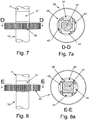
- the section of the second drill (11) that includes the drive section (21) is shown in more detail.
- the drive section (21) is located between the primary section (12) and the secondary section (13) of the second drill (11).
- Figure 5a is a cross section of the drive section (21) in the direction of arrows A-A in Figure 5
- Figure 5b is a cross sectional view of the primary section (12) of the second drill (11) in the direction of arrows B-B in Figure 5
- the cross section of the primary section (12) is circular and the same as the secondary section (13).
- the cross section, A-A, of the drive section (21) is a square with the distance between opposing faces equal to the diameter of the circular cross section, B-B, of the primary section (12).
- the sun gear (33) includes an engagement section (39).
- the engagement section (39) includes a pair of first contact means (40) and a pair of second contact means (41) is shown in plan view with the sun gear (33) lying on the x-y plane.
- Each contact means (40) is a cylindrical roller on a co-axial shaft.
- first contact means (40) are parallel and the second contact means (41) are parallel but the first contact means (40) lie perpendicular to the second contact means (41).
- the distance between the pair of first contact means (40) is equal to the diameter of the primary section (12) with each first contact means (40) equidistant from the centre of the sun gear (33).
- the distance between the pair of second contact means (40) is equal to the diameter of the primary section (12) with each second contact means (40) equidistant from the centre of the sun gear (33).
- cross-section A-A is not a square then the distance between respective pairs of contact means (40,41) will depend on the faces of the drive section (21) each pair of contact means (40,41) is intended to engage with.
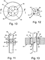
- Figure 6a is a cross sectional view in the direction of arrows C-C through the sun gear (33).
- Figure 6a is a cross sectional view of the sun gear (33) viewed in the x-z plane.
- the first contact means (40) are parallel to each other and the centreline of the sun gear (33).
- the second contact means (41) are approximately perpendicular to each other and the centreline of the sun gear (33).
- the contact means (40,41) incorporates a long rotatable member (cylindrical roller in this case) to reduce friction
- this rotatable member must be either parallel to, or angle with respect to, the centreline of the sun gear (33) to minimise scuffing.
- the optimum angle of the contact means (40,41) with respect to the centreline of the sun gear (33) will depend on the diameter of the contact means (40,41) and the diameter of the primary section (12).
- Figure 7, 7a, 8 and 8a are cross section views in the direction of arrows D-D and E-E respectively.
- the drill assembly (2) When forming a granular stone column the drill assembly (2) is rotated and inserted into the ground during insertion it may be desirable to keep the first and second drills (10,11) rotating the same way. When the drill assembly (2) reaches the required depth the aggregate forming the granular stone column needs to be fed to the base of the drill assembly as the drill assembly (2) is removed. In this case it may be desirable to rotate the first and second drills (10,11) in opposite directions. If the second drill (11) incorporates the drive section (21) and a sun gear (33) with the engagement section (39) is used this opposite rotation can be easily accomplished. Without the engagement section (39) and drive section (21) present two separate drive means, one for each drill (10,11), are likely to be required.
- the gearbox may not be an epicyclic gearbox but the engagement section (39) may still be present in one of the gears.
- the cross section A-A need not be square it can be any polygon where the distance between at least one pair of opposing parallel faces is equal to the diameter of the primary section (12).
- the cross section A-A could be a regular hexagon, a rectangle or any other suitable shape.
- contact means (40) may simply be the inner walls of a socket that is internally dimensioned to engage with the drive section (21).
- the contact means (40) could be bronze or a self lubricating, and/or low friction, solid material (metal, polymer or ceramic for example).
- each contact means (40) may simply be blocks or strips of suitable material, in this case they are likely to be a self-lubricating and/or low friction material, such as bronze, a polymer or a ceramic.
- each contact means (40) may simply include one or more rotating member that contacts the surface of the primary section (12) or drive section (21).
- the guide channel (22) could be formed into a ring of material attached to the retention structure (25) and the guidance means (26) attached to the second drill (11).
- the guidance means (26) would still move along the guide channel (22) but they would rotate with the second drill (11) whenever it was being driven rather than remain static with regards to the column assembly (2).
- FIG. 9 a second embodiment of the column assembly (1) is shown with the hopper (3) and the crane excavator (5) removed for clarity.
- a rotary head (50) of known type is shown, this rotary head (50) is configured to rotate the first drill (10).
- the first drill (10) includes an expanded section (51) located close to or at the primary end (15a).
- the expanded section (51) is essentially two truncated cones separated by a cylindrical section, where the bases of the cones are coterminous with the ends of the cylinder.
- Figure 9 shows optional alpha and beta first flights (52, 53), which are flights on the outside of the first drill (10).
- the alpha and beta first flights (52, 53) may have the same handedness or opposite handedness, and either may be the same handedness as the drill flight (18).
- FIG 9 the displacement unit (20) is shown within a displacement device (55) with two engagement tabs (56, 57) extending from an outer casing (6). Where the outer casing encloses (60), at least partially, the moving parts of the displacement device (55).
- the displacement device (55) includes the displacement unit (20) and the guidance means (26) housed within the outer casing (60).
- the movement device (16) is attached to the outer case (60) by an isolator (27).
- the isolator (27) rotationally isolates (co-axially) the movement device (16) and outer case (60) which means the electrical, hydraulic or pneumatic connections to the movement device (16) do not need to account for this.
- the isolator (27) is most likely to be a roller bearing, ball bearing, bush or similar, but anything that co-axially, rotationally, isolates the movement device (16) from the drills (10, 11), either directly or indirectly can be used.
- the first variation of the displacement device (55) is shown in Figure 9a and in this variation the displacement unit (20) is essentially the same as described for the first embodiment, with the guide channel (22) circumferentially cut into the outer surface of a cylinder attached to, or formed as part of, the second drill (11), but the guidance means (26) extend from an inner wall of the outer casing (60). It should be noted that the guidance means (26) may be attached to the outer casing (60) of the displacement device (20) directly or indirectly.
- FIG 9b a second variation of the displacement device (55) is shown in cross section, in this second variation the guidance means (26) are attached to the surface of the second drill (11) and the displacement unit (20) is attached to or formed as part of the outer casing (60).
- the displacement unit (20) is a ring with the guide channel (22) circumferentially cut into the inside wall (61).
- displacement space (62) which is a void, between the second terminal end (15) of the second drill (11) and the outer casing (60) to allow the second drill (11) to be displaced relative to the displacement (55) when the displacement device (55) is in use.
- the dimensions of the displacement space (62) are such that when in use the second drill (11) cannot contact the outer casing (60).
- the sun gear (33) with an engagement section (39) including a first aperture (65) is shown in plan view.
- the first aperture (65) passes through the entire thickness of the sun gear (33).
- the first aperture (65) is the combination of a cross with all arms equal in length and a circle, the centres of the cross, the circle and the sun gear (33) are coincident.
- the arms of the cross form four drive channels (66) through the sun gear (33).
- the diameter of the circle is d1.
- FIG. 11 and 12 a portion of the secondary section (13) and a cross sectional view of the drive section (21) respectively, are shown.
- the second drill (11) shaft in the drive section (21) is essentially square in cross-section with a maximum diagonal dimension of d2, where d2 is less than or at most equal to d1.
- the drive section (13) further includes 4 pairs of drive units (67), where one drive unit (67) of each pair is located on diametrically opposed faces of the second drill (11) shaft to the other.
- Each drive unit (67) is a wheel or roller configured to rotate on a drive rod (68) to which it is attached.
- Each drive rod (68) is a shaft that extends approximately perpendicularly from a face (69) of the drive section (21). In some cases the drive rod (68) will extend through the second drill (11) shaft joining pairs of drive units together.
- each drive rod (68) is perpendicular to, and passes through the centreline of the second drill (11).
- Figure 13 shows a cross sectional view of the sun gear (33) and drive section (21) of the second embodiment engaged in the drive position. In the drive position the sun gear (33) can rotationally drive the second drill (11).
- each drive unit (67) In the drive position the drive units (67) have been pushed into a complementary drive channel (66), as such each drive unit (67) is dimensioned to fit within the associated drive channel (66).
- Figure 14 the column assembly (1) is shown in a first or insertion position, where the displacement device (55) is disengaged and the second drill (11) is not being driven by the gearbox (17).
- the drill assembly (2) In this position the drill assembly (2) is inserted into the ground to start the formation of a granular stone column, the first drill (10) is rotated by the rotary head (50) and it is forced into the ground.
- the second drill (11) may be stationary or rotated during this step (for example with the first drill (10)).
- the lock device (70) is a thick walled tube that lies co-axial with the second drill (11) which includes engagement apertures (71).
- Each engagement aperture (71) is a slot that extends into the lock device (70) that is dimensioned and configured to accept an engagement tab (56, 57).
- the movement device (16) pushes the second drill (11) relative to the first drill (10).
- the movement device (16) then causes the first terminal end (14) to extend away from the primary end (15a).
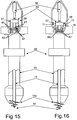
- the movement device (16) continues to push the second drill (11) through the first drill (10) until, as shown in Figure 15 , the drive units (67) are engaged with the drive channels (66), in this second position the gearbox (17) can drive the second drill (11) to feed any aggregate within the first drill (10) out of the primary end (15a) to form a stone column as the drill assembly (2) is withdrawn from the ground.
- the displacement device (55) can now displace the first and second drills (10, 11) relative to each other as the drill assembly is withdrawn from the ground.
- the differential lengthwise motion of the second drill (11) relative to the first drill (10) minimises the chance of the aggregate bridging helping to produce a uniform quality stone column.
- the displacement device (55) is also believed to assist with the compaction of the stone column.
- engagement tags (56, 57) on the displacement device (55) are optional and an alternative method of engaging the displacement device (55) can be used.
- the drive channels (66) may have a different cross section, for example the cross section may be semi-circular. In this case the drive units (67) will have a complementary shape.
- the drive units (67) are permanently attached to the associated drive rod (68) and this configured to rotate. In still other embodiments the drive units (67) are not configured to rotate, they act merely as drive keys.
- gearbox (17) is described as an epicyclic gearbox it can be any suitable form of gearbox (17) that allows the rotary head (50) to directly drive the first drill (10) and indirectly, via the gearbox (17), drive the second drill (11).
- the guidance means (26) operate cooperatively with the guide channel (22) to move the displacement unit (20) or guidance means (26) and the second drill (11) co-axially with respect to the first drill (10).
Priority Applications (2)
| Application Number | Priority Date | Filing Date | Title |
|---|---|---|---|
| RS20170508A RS55966B1 (sr) | 2012-12-10 | 2013-12-10 | Modifikovani bušaći uređaj za stubove od zrnastog kamena |
| HRP20170752TT HRP20170752T1 (hr) | 2012-12-10 | 2017-05-19 | Modificirana bušilica za bušenje stupova od zrnastog kamena |
Applications Claiming Priority (2)
| Application Number | Priority Date | Filing Date | Title |
|---|---|---|---|
| NZ60423412 | 2012-12-10 | ||
| PCT/IB2013/060759 WO2014091395A1 (en) | 2012-12-10 | 2013-12-10 | Modified stone column drill |
Publications (3)
| Publication Number | Publication Date |
|---|---|
| EP2929092A1 EP2929092A1 (en) | 2015-10-14 |
| EP2929092A4 EP2929092A4 (en) | 2016-08-24 |
| EP2929092B1 true EP2929092B1 (en) | 2017-05-03 |
Family
ID=50933819
Family Applications (1)
| Application Number | Title | Priority Date | Filing Date |
|---|---|---|---|
| EP13863194.0A Active EP2929092B1 (en) | 2012-12-10 | 2013-12-10 | Modified stone column drill |
Country Status (12)
| Country | Link |
|---|---|
| US (1) | US9365997B2 (es) |
| EP (1) | EP2929092B1 (es) |
| CN (1) | CN104838071B (es) |
| AU (1) | AU2013356921B2 (es) |
| BR (1) | BR112015013280B1 (es) |
| DK (1) | DK2929092T3 (es) |
| EA (1) | EA029087B1 (es) |
| ES (1) | ES2626455T3 (es) |
| HR (1) | HRP20170752T1 (es) |
| PT (1) | PT2929092T (es) |
| RS (1) | RS55966B1 (es) |
| WO (1) | WO2014091395A1 (es) |
Families Citing this family (9)
| Publication number | Priority date | Publication date | Assignee | Title |
|---|---|---|---|---|
| DE102015105908A1 (de) * | 2015-04-17 | 2016-10-20 | Bauer Maschinen Gmbh | Bohrgerät zum Erstellen einer verrohrten Bohrung und Verfahren zum Betreiben eines Bohrgerätes |
| CA2957950C (en) * | 2016-02-15 | 2020-05-12 | Edaphis Inc. | Porous medium extraction system, porous medium sensor assembly and porous medium infiltrometer |
| MX2018015384A (es) | 2016-07-08 | 2019-04-29 | Lyell Mcmillan Jaron | Dispositivo de desplazamiento y/o compactacion. |
| CN107461042B (zh) * | 2017-03-06 | 2019-06-04 | 扬州珠峰户外用品有限公司 | 一种遮阳棚支脚 |
| CN107461044B (zh) * | 2017-03-06 | 2019-05-31 | 广州市御品阳篷有限公司 | 一种遮阳棚支脚结构 |
| CN107461043B (zh) * | 2017-03-06 | 2019-05-14 | 永康市天地工具有限公司 | 一种户外遮阳棚支脚 |
| SI3830345T1 (sl) | 2019-04-03 | 2023-04-28 | Jaron Lyell Mcmillan | Sveder za tvorjenje kamnitih slopov v tleh |
| CN109972607B (zh) * | 2019-04-25 | 2024-04-26 | 中国水电基础局有限公司 | 钻削振冲器和振冲碎石桩机 |
| CA3230313A1 (en) * | 2021-08-31 | 2023-03-09 | Alan Conte Matthew | A system and method for installing an aggregate pier |
Family Cites Families (25)
| Publication number | Priority date | Publication date | Assignee | Title |
|---|---|---|---|---|
| US3303656A (en) * | 1962-12-21 | 1967-02-14 | Richard E Landau | Method and apparatus for constructing columns of material in soil |
| JPS4946968B1 (es) * | 1971-05-25 | 1974-12-13 | ||
| US3766741A (en) * | 1972-03-09 | 1973-10-23 | Raymond Int Inc | Pile driving |
| US3828864A (en) * | 1973-02-26 | 1974-08-13 | H & M Vibro Inc | Pile driver and extractor |
| US3962879A (en) * | 1973-05-03 | 1976-06-15 | Turzillo Lee A | Reinforced pile in earth situs and method of producing same |
| US4074778A (en) * | 1976-07-14 | 1978-02-21 | The United States Of America As Represented By The Secretary Of The Interior | Square hole drill |
| JPS586011B2 (ja) * | 1980-04-15 | 1983-02-02 | 栗本 中富 | 砂杭造成装置 |
| AU552443B2 (en) * | 1981-09-22 | 1986-05-29 | Fudo Construction Co. Ltd. | Compacting soils |
| FR2626025B1 (fr) * | 1988-01-14 | 1990-07-13 | Minaberry Michel | Dispositif pour le forage des sols |
| DE4220976C1 (es) * | 1992-06-26 | 1993-07-15 | Delmag Maschinenfabrik Reinhold Dornfeld Gmbh & Co, 7300 Esslingen, De | |
| JP3241235B2 (ja) | 1995-05-01 | 2001-12-25 | 株式会社ヒメノ | 孔掘削工法及び孔掘削装置 |
| BE1010638A3 (nl) * | 1996-09-20 | 1998-11-03 | Poorteman Frank | Boor voor het maken van een paal in de grond en werkwijze die deze boor toepast. |
| US6142711A (en) * | 1999-04-05 | 2000-11-07 | Goughnour; R. Robert | Vibrator having a rotating and oscillating housing |
| NL1012243C2 (nl) * | 1999-06-04 | 2000-12-12 | Voorbij Groep Bv | Werkwijze en inrichting voor het in de bodem vervaardigen van een paal. |
| US6957930B2 (en) * | 1999-09-01 | 2005-10-25 | Landau Richard E | Apparatus to form columns of granular material |
| FR2807455B1 (fr) * | 2000-04-11 | 2004-04-02 | Cie Du Sol | Machine pour la realisation de pieux fores |
| DE10132753A1 (de) * | 2000-07-12 | 2002-03-07 | Peter C Rozendaal | Richtbohrräumer mit Planetengetriebe |
| CN2541598Y (zh) * | 2002-03-28 | 2003-03-26 | 张昌平 | 一种星形运动的大直径桩基础工程成孔钻具 |
| ATE408731T1 (de) * | 2006-04-26 | 2008-10-15 | Bauer Maschinen Gmbh | Bohrgerät und verfahren zum erstellen einer bohrsäule im boden |
| PL1849918T3 (pl) * | 2006-04-26 | 2011-07-29 | Bauer Maschinen Gmbh | Urządzenie wiertnicze do wykonywania słupa wiertniczego w ziemi |
| US8926228B2 (en) * | 2006-09-08 | 2015-01-06 | Ben Stroyer | Auger grouted displacement pile |
| US9068409B2 (en) * | 2009-08-19 | 2015-06-30 | Leonardo Mohamed | Multifunctional screw drill and reaming device |
| BR112012005623A2 (pt) * | 2009-09-15 | 2016-06-21 | Managed Pressure Operations | método para perfurar um furo de poço substerrâneo. |
| CN201802310U (zh) * | 2010-02-03 | 2011-04-20 | 国家电网公司直流建设分公司 | 掏挖钻机 |
| US9115477B2 (en) * | 2011-04-04 | 2015-08-25 | Jaron Lyell Mcmillan | Machine and method for forming an in ground granular column |
-
2013
- 2013-12-10 PT PT138631940T patent/PT2929092T/pt unknown
- 2013-12-10 EP EP13863194.0A patent/EP2929092B1/en active Active
- 2013-12-10 CN CN201380064402.1A patent/CN104838071B/zh active Active
- 2013-12-10 RS RS20170508A patent/RS55966B1/sr unknown
- 2013-12-10 EA EA201591032A patent/EA029087B1/ru unknown
- 2013-12-10 DK DK13863194.0T patent/DK2929092T3/en active
- 2013-12-10 BR BR112015013280-4A patent/BR112015013280B1/pt active IP Right Grant
- 2013-12-10 WO PCT/IB2013/060759 patent/WO2014091395A1/en active Application Filing
- 2013-12-10 AU AU2013356921A patent/AU2013356921B2/en active Active
- 2013-12-10 ES ES13863194.0T patent/ES2626455T3/es active Active
- 2013-12-10 US US14/648,263 patent/US9365997B2/en active Active
-
2017
- 2017-05-19 HR HRP20170752TT patent/HRP20170752T1/hr unknown
Non-Patent Citations (1)
| Title |
|---|
| None * |
Also Published As
| Publication number | Publication date |
|---|---|
| BR112015013280A2 (pt) | 2017-07-11 |
| HRP20170752T1 (hr) | 2017-08-11 |
| EA201591032A1 (ru) | 2015-12-30 |
| BR112015013280B1 (pt) | 2021-03-16 |
| AU2013356921B2 (en) | 2016-02-11 |
| RS55966B1 (sr) | 2017-09-29 |
| US9365997B2 (en) | 2016-06-14 |
| AU2013356921A1 (en) | 2015-05-14 |
| PT2929092T (pt) | 2017-06-02 |
| CN104838071A (zh) | 2015-08-12 |
| WO2014091395A1 (en) | 2014-06-19 |
| EA029087B1 (ru) | 2018-02-28 |
| US20150322641A1 (en) | 2015-11-12 |
| DK2929092T3 (en) | 2017-06-06 |
| EP2929092A1 (en) | 2015-10-14 |
| EP2929092A4 (en) | 2016-08-24 |
| CN104838071B (zh) | 2017-04-05 |
| ES2626455T3 (es) | 2017-07-25 |
Similar Documents
| Publication | Publication Date | Title |
|---|---|---|
| EP2929092B1 (en) | Modified stone column drill | |
| EP2694744B1 (en) | Machine and method for forming an in ground granular column | |
| RU188154U1 (ru) | Инструмент для шнекового бурения горизонтальных и слабонаклонных скважин | |
| CN100485156C (zh) | 多轴钻机及其施工方法 | |
| CN108589710B (zh) | 一种市政工程用的弧形方桩成型设备 | |
| NZ618804B (en) | Modified stone column drill | |
| NZ618804A (en) | Modified stone column drill | |
| CN109056726B (zh) | 一种市政路桥工程使用的扩桩设备 | |
| CN110118061B (zh) | 双层反向环状钻头及其施工方法 | |
| JPS61142287A (ja) | 地中に円形ボ−リング穴を形成するための装置 | |
| CN115478785A (zh) | 一种具有自动调节功能的钻井装置及钻井方法 | |
| CN111608678B (zh) | 一种易施工的市政顶管装置 | |
| EP3482005B1 (en) | Displacement and/or compaction device | |
| CN108729852B (zh) | 一种市政工程用的弧形地桩螺旋钻 | |
| EP3830345B1 (en) | Drill for forming stone column in the ground | |
| CN215927280U (zh) | 一种套管施工装置 | |
| CN109681208B (zh) | 一种摆动式等直径多刀盘包络成形全断面钻具 | |
| RU2054506C1 (ru) | Устройство для образования скважин в грунте методом раскатки | |
| RU2319808C1 (ru) | Способ возведения буронабивной сваи | |
| SU945300A1 (ru) | Установка горизонтального бурени | |
| AU2018315044A1 (en) | Tunnel boring machine |
Legal Events
| Date | Code | Title | Description |
|---|---|---|---|
| PUAI | Public reference made under article 153(3) epc to a published international application that has entered the european phase |
Free format text: ORIGINAL CODE: 0009012 |
|
| 17P | Request for examination filed |
Effective date: 20150622 |
|
| AK | Designated contracting states |
Kind code of ref document: A1 Designated state(s): AL AT BE BG CH CY CZ DE DK EE ES FI FR GB GR HR HU IE IS IT LI LT LU LV MC MK MT NL NO PL PT RO RS SE SI SK SM TR |
|
| AX | Request for extension of the european patent |
Extension state: BA ME |
|
| DAX | Request for extension of the european patent (deleted) | ||
| RA4 | Supplementary search report drawn up and despatched (corrected) |
Effective date: 20160726 |
|
| RIC1 | Information provided on ipc code assigned before grant |
Ipc: E02D 3/10 20060101ALI20160720BHEP Ipc: E02D 3/12 20060101ALI20160720BHEP Ipc: E02D 3/08 20060101AFI20160720BHEP |
|
| GRAP | Despatch of communication of intention to grant a patent |
Free format text: ORIGINAL CODE: EPIDOSNIGR1 |
|
| STAA | Information on the status of an ep patent application or granted ep patent |
Free format text: STATUS: GRANT OF PATENT IS INTENDED |
|
| INTG | Intention to grant announced |
Effective date: 20161116 |
|
| GRAJ | Information related to disapproval of communication of intention to grant by the applicant or resumption of examination proceedings by the epo deleted |
Free format text: ORIGINAL CODE: EPIDOSDIGR1 |
|
| STAA | Information on the status of an ep patent application or granted ep patent |
Free format text: STATUS: REQUEST FOR EXAMINATION WAS MADE |
|
| GRAS | Grant fee paid |
Free format text: ORIGINAL CODE: EPIDOSNIGR3 |
|
| STAA | Information on the status of an ep patent application or granted ep patent |
Free format text: STATUS: GRANT OF PATENT IS INTENDED |
|
| GRAP | Despatch of communication of intention to grant a patent |
Free format text: ORIGINAL CODE: EPIDOSNIGR1 |
|
| INTC | Intention to grant announced (deleted) | ||
| GRAA | (expected) grant |
Free format text: ORIGINAL CODE: 0009210 |
|
| STAA | Information on the status of an ep patent application or granted ep patent |
Free format text: STATUS: THE PATENT HAS BEEN GRANTED |
|
| INTG | Intention to grant announced |
Effective date: 20170316 |
|
| AK | Designated contracting states |
Kind code of ref document: B1 Designated state(s): AL AT BE BG CH CY CZ DE DK EE ES FI FR GB GR HR HU IE IS IT LI LT LU LV MC MK MT NL NO PL PT RO RS SE SI SK SM TR |
|
| REG | Reference to a national code |
Ref country code: GB Ref legal event code: FG4D |
|
| REG | Reference to a national code |
Ref country code: AT Ref legal event code: REF Ref document number: 890142 Country of ref document: AT Kind code of ref document: T Effective date: 20170515 Ref country code: CH Ref legal event code: EP |
|
| REG | Reference to a national code |
Ref country code: HR Ref legal event code: TUEP Ref document number: P20170752 Country of ref document: HR |
|
| REG | Reference to a national code |
Ref country code: NL Ref legal event code: FP |
|
| REG | Reference to a national code |
Ref country code: IE Ref legal event code: FG4D |
|
| REG | Reference to a national code |
Ref country code: PT Ref legal event code: SC4A Ref document number: 2929092 Country of ref document: PT Date of ref document: 20170602 Kind code of ref document: T Free format text: AVAILABILITY OF NATIONAL TRANSLATION Effective date: 20170519 |
|
| REG | Reference to a national code |
Ref country code: DK Ref legal event code: T3 Effective date: 20170531 |
|
| REG | Reference to a national code |
Ref country code: SE Ref legal event code: TRGR |
|
| REG | Reference to a national code |
Ref country code: DE Ref legal event code: R096 Ref document number: 602013020819 Country of ref document: DE |
|
| REG | Reference to a national code |
Ref country code: ES Ref legal event code: FG2A Ref document number: 2626455 Country of ref document: ES Kind code of ref document: T3 Effective date: 20170725 |
|
| REG | Reference to a national code |
Ref country code: HR Ref legal event code: T1PR Ref document number: P20170752 Country of ref document: HR |
|
| REG | Reference to a national code |
Ref country code: AT Ref legal event code: MK05 Ref document number: 890142 Country of ref document: AT Kind code of ref document: T Effective date: 20170503 |
|
| REG | Reference to a national code |
Ref country code: LT Ref legal event code: MG4D |
|
| PG25 | Lapsed in a contracting state [announced via postgrant information from national office to epo] |
Ref country code: FI Free format text: LAPSE BECAUSE OF FAILURE TO SUBMIT A TRANSLATION OF THE DESCRIPTION OR TO PAY THE FEE WITHIN THE PRESCRIBED TIME-LIMIT Effective date: 20170503 Ref country code: LT Free format text: LAPSE BECAUSE OF FAILURE TO SUBMIT A TRANSLATION OF THE DESCRIPTION OR TO PAY THE FEE WITHIN THE PRESCRIBED TIME-LIMIT Effective date: 20170503 Ref country code: GR Free format text: LAPSE BECAUSE OF FAILURE TO SUBMIT A TRANSLATION OF THE DESCRIPTION OR TO PAY THE FEE WITHIN THE PRESCRIBED TIME-LIMIT Effective date: 20170804 Ref country code: AT Free format text: LAPSE BECAUSE OF FAILURE TO SUBMIT A TRANSLATION OF THE DESCRIPTION OR TO PAY THE FEE WITHIN THE PRESCRIBED TIME-LIMIT Effective date: 20170503 Ref country code: NO Free format text: LAPSE BECAUSE OF FAILURE TO SUBMIT A TRANSLATION OF THE DESCRIPTION OR TO PAY THE FEE WITHIN THE PRESCRIBED TIME-LIMIT Effective date: 20170803 |
|
| PG25 | Lapsed in a contracting state [announced via postgrant information from national office to epo] |
Ref country code: LV Free format text: LAPSE BECAUSE OF FAILURE TO SUBMIT A TRANSLATION OF THE DESCRIPTION OR TO PAY THE FEE WITHIN THE PRESCRIBED TIME-LIMIT Effective date: 20170503 Ref country code: PL Free format text: LAPSE BECAUSE OF FAILURE TO SUBMIT A TRANSLATION OF THE DESCRIPTION OR TO PAY THE FEE WITHIN THE PRESCRIBED TIME-LIMIT Effective date: 20170503 Ref country code: BG Free format text: LAPSE BECAUSE OF FAILURE TO SUBMIT A TRANSLATION OF THE DESCRIPTION OR TO PAY THE FEE WITHIN THE PRESCRIBED TIME-LIMIT Effective date: 20170803 Ref country code: IS Free format text: LAPSE BECAUSE OF FAILURE TO SUBMIT A TRANSLATION OF THE DESCRIPTION OR TO PAY THE FEE WITHIN THE PRESCRIBED TIME-LIMIT Effective date: 20170903 |
|
| REG | Reference to a national code |
Ref country code: FR Ref legal event code: PLFP Year of fee payment: 5 |
|
| PG25 | Lapsed in a contracting state [announced via postgrant information from national office to epo] |
Ref country code: SK Free format text: LAPSE BECAUSE OF FAILURE TO SUBMIT A TRANSLATION OF THE DESCRIPTION OR TO PAY THE FEE WITHIN THE PRESCRIBED TIME-LIMIT Effective date: 20170503 Ref country code: EE Free format text: LAPSE BECAUSE OF FAILURE TO SUBMIT A TRANSLATION OF THE DESCRIPTION OR TO PAY THE FEE WITHIN THE PRESCRIBED TIME-LIMIT Effective date: 20170503 Ref country code: CZ Free format text: LAPSE BECAUSE OF FAILURE TO SUBMIT A TRANSLATION OF THE DESCRIPTION OR TO PAY THE FEE WITHIN THE PRESCRIBED TIME-LIMIT Effective date: 20170503 Ref country code: RO Free format text: LAPSE BECAUSE OF FAILURE TO SUBMIT A TRANSLATION OF THE DESCRIPTION OR TO PAY THE FEE WITHIN THE PRESCRIBED TIME-LIMIT Effective date: 20170503 |
|
| REG | Reference to a national code |
Ref country code: DE Ref legal event code: R097 Ref document number: 602013020819 Country of ref document: DE |
|
| PG25 | Lapsed in a contracting state [announced via postgrant information from national office to epo] |
Ref country code: SM Free format text: LAPSE BECAUSE OF FAILURE TO SUBMIT A TRANSLATION OF THE DESCRIPTION OR TO PAY THE FEE WITHIN THE PRESCRIBED TIME-LIMIT Effective date: 20170503 |
|
| PLBE | No opposition filed within time limit |
Free format text: ORIGINAL CODE: 0009261 |
|
| STAA | Information on the status of an ep patent application or granted ep patent |
Free format text: STATUS: NO OPPOSITION FILED WITHIN TIME LIMIT |
|
| 26N | No opposition filed |
Effective date: 20180206 |
|
| PG25 | Lapsed in a contracting state [announced via postgrant information from national office to epo] |
Ref country code: SI Free format text: LAPSE BECAUSE OF FAILURE TO SUBMIT A TRANSLATION OF THE DESCRIPTION OR TO PAY THE FEE WITHIN THE PRESCRIBED TIME-LIMIT Effective date: 20170503 |
|
| REG | Reference to a national code |
Ref country code: CH Ref legal event code: PL |
|
| REG | Reference to a national code |
Ref country code: IE Ref legal event code: MM4A |
|
| PG25 | Lapsed in a contracting state [announced via postgrant information from national office to epo] |
Ref country code: LU Free format text: LAPSE BECAUSE OF NON-PAYMENT OF DUE FEES Effective date: 20171210 Ref country code: MT Free format text: LAPSE BECAUSE OF NON-PAYMENT OF DUE FEES Effective date: 20171210 |
|
| PG25 | Lapsed in a contracting state [announced via postgrant information from national office to epo] |
Ref country code: IE Free format text: LAPSE BECAUSE OF NON-PAYMENT OF DUE FEES Effective date: 20171210 |
|
| PG25 | Lapsed in a contracting state [announced via postgrant information from national office to epo] |
Ref country code: LI Free format text: LAPSE BECAUSE OF NON-PAYMENT OF DUE FEES Effective date: 20171231 Ref country code: CH Free format text: LAPSE BECAUSE OF NON-PAYMENT OF DUE FEES Effective date: 20171231 |
|
| REG | Reference to a national code |
Ref country code: HR Ref legal event code: ODRP Ref document number: P20170752 Country of ref document: HR Payment date: 20181128 Year of fee payment: 6 |
|
| PG25 | Lapsed in a contracting state [announced via postgrant information from national office to epo] |
Ref country code: HU Free format text: LAPSE BECAUSE OF FAILURE TO SUBMIT A TRANSLATION OF THE DESCRIPTION OR TO PAY THE FEE WITHIN THE PRESCRIBED TIME-LIMIT; INVALID AB INITIO Effective date: 20131210 Ref country code: MC Free format text: LAPSE BECAUSE OF FAILURE TO SUBMIT A TRANSLATION OF THE DESCRIPTION OR TO PAY THE FEE WITHIN THE PRESCRIBED TIME-LIMIT Effective date: 20170503 |
|
| PG25 | Lapsed in a contracting state [announced via postgrant information from national office to epo] |
Ref country code: CY Free format text: LAPSE BECAUSE OF FAILURE TO SUBMIT A TRANSLATION OF THE DESCRIPTION OR TO PAY THE FEE WITHIN THE PRESCRIBED TIME-LIMIT Effective date: 20170503 |
|
| PG25 | Lapsed in a contracting state [announced via postgrant information from national office to epo] |
Ref country code: MK Free format text: LAPSE BECAUSE OF FAILURE TO SUBMIT A TRANSLATION OF THE DESCRIPTION OR TO PAY THE FEE WITHIN THE PRESCRIBED TIME-LIMIT Effective date: 20170503 |
|
| REG | Reference to a national code |
Ref country code: HR Ref legal event code: ODRP Ref document number: P20170752 Country of ref document: HR Payment date: 20191128 Year of fee payment: 7 |
|
| PG25 | Lapsed in a contracting state [announced via postgrant information from national office to epo] |
Ref country code: AL Free format text: LAPSE BECAUSE OF FAILURE TO SUBMIT A TRANSLATION OF THE DESCRIPTION OR TO PAY THE FEE WITHIN THE PRESCRIBED TIME-LIMIT Effective date: 20170503 |
|
| REG | Reference to a national code |
Ref country code: HR Ref legal event code: ODRP Ref document number: P20170752 Country of ref document: HR Payment date: 20201130 Year of fee payment: 8 |
|
| REG | Reference to a national code |
Ref country code: HR Ref legal event code: ODRP Ref document number: P20170752 Country of ref document: HR Payment date: 20211208 Year of fee payment: 9 |
|
| REG | Reference to a national code |
Ref country code: HR Ref legal event code: ODRP Ref document number: P20170752 Country of ref document: HR Payment date: 20221206 Year of fee payment: 10 |
|
| PGFP | Annual fee paid to national office [announced via postgrant information from national office to epo] |
Ref country code: ES Payment date: 20230105 Year of fee payment: 10 |
|
| P01 | Opt-out of the competence of the unified patent court (upc) registered |
Effective date: 20230518 |
|
| REG | Reference to a national code |
Ref country code: HR Ref legal event code: ODRP Ref document number: P20170752 Country of ref document: HR Payment date: 20231123 Year of fee payment: 11 |
|
| PGFP | Annual fee paid to national office [announced via postgrant information from national office to epo] |
Ref country code: GB Payment date: 20231229 Year of fee payment: 11 |
|
| PGFP | Annual fee paid to national office [announced via postgrant information from national office to epo] |
Ref country code: TR Payment date: 20231211 Year of fee payment: 11 Ref country code: SE Payment date: 20231228 Year of fee payment: 11 Ref country code: RS Payment date: 20231127 Year of fee payment: 11 Ref country code: PT Payment date: 20231124 Year of fee payment: 11 Ref country code: NL Payment date: 20231222 Year of fee payment: 11 Ref country code: IT Payment date: 20231219 Year of fee payment: 11 Ref country code: HR Payment date: 20231123 Year of fee payment: 11 Ref country code: FR Payment date: 20231219 Year of fee payment: 11 Ref country code: DK Payment date: 20231229 Year of fee payment: 11 |
|
| PGFP | Annual fee paid to national office [announced via postgrant information from national office to epo] |
Ref country code: BE Payment date: 20231219 Year of fee payment: 11 |
|
| PGFP | Annual fee paid to national office [announced via postgrant information from national office to epo] |
Ref country code: ES Payment date: 20240110 Year of fee payment: 11 |
|
| PGFP | Annual fee paid to national office [announced via postgrant information from national office to epo] |
Ref country code: DE Payment date: 20231222 Year of fee payment: 11 |