EP2927624A2 - Anlaufspurkühlsystem für eine Skisprungschanze - Google Patents
Anlaufspurkühlsystem für eine Skisprungschanze Download PDFInfo
- Publication number
- EP2927624A2 EP2927624A2 EP15161076.3A EP15161076A EP2927624A2 EP 2927624 A2 EP2927624 A2 EP 2927624A2 EP 15161076 A EP15161076 A EP 15161076A EP 2927624 A2 EP2927624 A2 EP 2927624A2
- Authority
- EP
- European Patent Office
- Prior art keywords
- cooling
- track
- run
- cooling system
- edge
- Prior art date
- Legal status (The legal status is an assumption and is not a legal conclusion. Google has not performed a legal analysis and makes no representation as to the accuracy of the status listed.)
- Granted
Links
Images




Classifications
-
- F—MECHANICAL ENGINEERING; LIGHTING; HEATING; WEAPONS; BLASTING
- F25—REFRIGERATION OR COOLING; COMBINED HEATING AND REFRIGERATION SYSTEMS; HEAT PUMP SYSTEMS; MANUFACTURE OR STORAGE OF ICE; LIQUEFACTION SOLIDIFICATION OF GASES
- F25C—PRODUCING, WORKING OR HANDLING ICE
- F25C3/00—Processes or apparatus specially adapted for producing ice or snow for winter sports or similar recreational purposes, e.g. for sporting installations; Producing artificial snow
- F25C3/04—Processes or apparatus specially adapted for producing ice or snow for winter sports or similar recreational purposes, e.g. for sporting installations; Producing artificial snow for sledging or ski trails; Producing artificial snow
-
- A—HUMAN NECESSITIES
- A63—SPORTS; GAMES; AMUSEMENTS
- A63C—SKATES; SKIS; ROLLER SKATES; DESIGN OR LAYOUT OF COURTS, RINKS OR THE LIKE
- A63C19/00—Design or layout of playing courts, rinks, bowling greens or areas for water-skiing; Covers therefor
- A63C19/10—Ice-skating or roller-skating rinks; Slopes or trails for skiing, ski-jumping or tobogganing
-
- E—FIXED CONSTRUCTIONS
- E01—CONSTRUCTION OF ROADS, RAILWAYS, OR BRIDGES
- E01C—CONSTRUCTION OF, OR SURFACES FOR, ROADS, SPORTS GROUNDS, OR THE LIKE; MACHINES OR AUXILIARY TOOLS FOR CONSTRUCTION OR REPAIR
- E01C13/00—Pavings or foundations specially adapted for playgrounds or sports grounds; Drainage, irrigation or heating of sports grounds
- E01C13/10—Pavings or foundations specially adapted for playgrounds or sports grounds; Drainage, irrigation or heating of sports grounds for artificial surfaces for outdoor or indoor practice of snow or ice sports
- E01C13/12—Pavings or foundations specially adapted for playgrounds or sports grounds; Drainage, irrigation or heating of sports grounds for artificial surfaces for outdoor or indoor practice of snow or ice sports for snow sports, e.g. skiing or ski tow track
-
- A—HUMAN NECESSITIES
- A63—SPORTS; GAMES; AMUSEMENTS
- A63C—SKATES; SKIS; ROLLER SKATES; DESIGN OR LAYOUT OF COURTS, RINKS OR THE LIKE
- A63C2201/00—Use of skates, skis, roller-skates, snowboards and courts
- A63C2201/04—Ski jumping
Definitions
- the invention relates to an inrun track cooling system for a ski jump.
- start-track cooling systems for ski jumping sport.
- the different variants take account of the fact that the climatic conditions change, so that the temperatures are often too warm and fluctuating even in the winter months in order to allow the formation and / or maintenance of a stable inrun track.
- flying hills are often used only for competitions and are therefore sometimes only a few days in the year in use.
- a mobile run-track cooling system is desirable that will only be assembled for the required period of use.
- the inrun track of a ski jump has two single tracks with two track edges each.
- a run-track cooling system which is suitable for cooling the run-up track of a ski jumping hill which extends along a start-up direction has, for example, floor cooling ducts which are fixed on cross members.
- a plurality of juxtaposed floor cooling ducts for guiding a liquid cooling medium is arranged running along the start-up direction and, viewed transversely to the start-up direction, in a common bottom cooling duct plane. They are arranged freely accessible at the top, ie the floor cooling pipes are exposed and are not covered by other components.
- a plurality along the start-up direction of spaced-apart cross member each extending transversely to the start-up direction, wherein the cross member for mounting the run-track cooling system on the substructure of a ski jump are suitable.
- a run-track cooling system is known.
- the cold floor cooling ducts arranged on the cross members are sprayed with water which quickly freezes on the floor cooling ducts. In this way, an ice sheet can be successively formed. If the ice layer sufficient Thickness has reached, then the two single tracks can be milled. In this way, the ice run-up track is formed.
- the ice surface of this ice run-up track is spaced at different distances from the floor cooling ducts. Since ice is a comparatively poor conductor of heat, despite the high cooling capacity in the floor cooling pipes there is a risk that the ice surface melts at least in the sections further away from the floor cooling ducts, for example in strong sunlight, while other areas of the ice run-up track remain frozen.
- a disadvantage of the known inrun tracking system is therefore in particular that the track edges of the Eisanlaufspur can become structurally unstable in use. As a result, it is not possible to ensure consistent conditions for the competitors during a competition over the duration of the competition.
- the object of the present invention is therefore to provide a run-up track cooling system for a ski jumping hill which has structurally more stable track edges in the individual tracks during the use of the ice run-up track in a competition.
- the track edge cooling elements are formed of a material having a thermal conductivity coefficient of more than 10 W / m ° K.
- a structural design is realized, which has an approximately constant small distance between the ice surface and in particular the ice surface cooling components in the form of floor cooling ducts and having the track edge cooling elements. This achieves a more even cooling of the ice run-up track.
- Another advantage of this run-track cooling system is that it can be easily formed as a mobile system.
- the heat conduction coefficient can be determined analogously to DIN 22007 if necessary.
- DIN 22007-1 to -4 describe in each case methods for measuring the thermal conductivity of polymeric plastics depending on the field of application or the measuring method. If necessary, the methods can be applied analogously to other materials and thermal conductivity coefficients.
- the thermal conductivity is determined using a commercially available hot plate.
- the track edge cooling elements preferably protrude more than two more preferably more than four inches above the bottom cooling line level upwards.
- the ice layer of the inrun track is less than 3cm, more preferably about 2cm thick. That is, the distance of the run-track surface, which must be kept at ambient temperatures above freezing and in sunlight to less than zero degrees, to the cooling capacity in the Ice-layer-bearing components is uniformly minimized viewed in cross-section of the run-in track system.
- the track edge cooling elements are formed from a material having a thermal conductivity coefficient of more than 50 W / m ° K, and preferably more than 100 W / m ° K.
- a material having the above coefficients of thermal conductivity ensures sufficient transport of thermal energy between the track edge cooling elements and the surface of the run-up track.
- the cooling element will be constructed of metallic materials. The highest thermal conductivity at comparatively manageable material and manufacturing costs offers aluminum.
- the cooling element can be formed particularly economically as a one-piece aluminum L-profile. The use of steel, especially stainless steel, is economical.
- the metallic materials are used in the form of a sheet.
- a plastic provided with carbon or a ceramic having a corresponding coefficient of thermal conductivity may be suitable as the material.
- the track edge cooling elements preferably have, viewed transversely to the start-up direction, a mounting leg oriented parallel to the cross members and a track edge leg projecting upwards out of the floor cooling line plane.
- This can be realized in the simplest case by an L-profile.
- Other profile shapes such as T- or U-profiles are used, as far as a mounting leg and a protruding from the bottom cooling line level track edge-leg are always formed.
- the parallel to the cross members oriented mounting leg is preferably connectable to the cross members.
- cross member and oriented to the crossmember mounting legs are each secured by at least one screw to each other.
- the mounting legs are Preferably arranged such that they point away from the floor cooling ducts and run on the mounting legs no floor cooling ducts.
- track edge cooling lines are provided in addition to the floor cooling lines, which extend above the floor cooling line level at the track edge legs of the track edge cooling elements.
- at least one holding element is arranged on the upstanding from the floor cooling line level track edge legs, which is suitable to hold a track edge cooling line.
- the track edge legs are cooled by means of a cooling medium circulating through the track edge cooling lines.
- the floor cooling ducts and track edge cooling ducts may be connected to each other so that a cooling medium can be conveyed through them and only one pump is required for conveying the cooling medium.
- the track edge cooling lines are preferably connected by means of holding elements with the track edge legs.
- the holding elements are each fastened with the track edge legs by means of screw connections and structurally designed such that a track edge cooling line can be fastened by means of insertion.
- the track edge cooling lines and / or the floor cooling lines are preferably connected to one another in a meandering manner.
- the track edge cooling lines and / or the floor cooling lines form a cooling line system, through which a cooling medium can be conveyed.
- the track edge cooling lines may be arranged on the side of the track edge leg facing the associated individual track. Alternatively or additionally, they may be arranged on the side facing away from the associated single track side of the track edge leg.
- cooling projections in the sense of the invention comprises any structure that protrudes from the track edge leg at least in sections into the single track. This is also a cooling line to understand which is parallel to the track edge leg on which it is mounted, as it represents a projection relative to the track edge leg.
- the feature of cooling projections also includes a plurality of individual projections, which extend transversely to the start-up direction and in the direction of the associated individual track, and are suitable for cooling in sections the ice of the inrun track in the region of the track edge legs. For all embodiments of the cooling projections applies that thereby a particularly good structural mechanical anchoring of the inrun track edges forming ice layers is achieved at the inrun track system.
- the cooling projections are formed starting from the track edge leg U-shaped.
- the cooling projections may be arranged as a branch pipe sections branching from the track edge cooling lines. Alternatively, adjacent cooling projections merge into one another in meandering fashion.
- the cooling projections are formed as line sections for the cooling medium of the run-track cooling system. That the cooling projections are part of a cooling pipe system.
- the cooling projections, the track edge cooling pipes and the floor cooling pipes are connected to each other so that a cooling medium flows through them and they are all connected to a pump, which circulates the cooling medium in operation.
- the cooling projections are formed integrally with the associated track edge leg. This ensures a particularly good heat conduction between the track edge limbs and the cooling protrusions formed integrally therefrom. In addition, this variant makes it possible to reduce the assembly time during assembly and disassembly of the run-track cooling system.
- the cooling projections are metal portions of the track edge leg bent out of the plane of extent of the track edge leg.
- sliding elements are arranged at end portions of the cooling projections, which are maximally spaced from the track edge legs.
- a material for the sliding elements is in particular a ceramic or a plastic. Of the ceramic materials in particular porcelain has advantageous properties.
- the skids have skid characteristics similar to those of ice. This ensures that even with incomplete icing of the cooling projections at the end portions users of the ice run-up track excellent sliding properties are provided.
- the sliding elements are preferably dimensioned such that they can be fastened by simply plugging on the cooling projections.
- a track edge sliding element made of plastic or ceramic is arranged in the upper region above the track edge leg.
- the track edge sliding extend parallel to the direction of entry and form in the single track, the sliding edges on which slide off the edges of the skis of a jumper.
- the track edge sliding elements are arranged in the direction of the bottom cooling line plane with a slight undercut.
- the track-edge sliding elements have sliding properties for the edges of skis that are comparable to those of ice. Therefore, formation of ice on the track edge slide members is not required.
- the run-track cooling is designed to form ice on the bottom of the trained and cooled by the run-track cooling single track and not at the track edges.
- the track edge sliding element is preferably designed such that it can be plugged onto the respective track edge cooling element, preferably the respective track edge leg.
- the track edge sliding elements are preferably each dimensioned so that they extend in the single track when using the run-track cooling in the direction of the mounting leg so that they are at least partially below the ice, which is formed on the bottom of the single track.
- the U-shaped cooling projections are each formed from a tube into which a partition wall is introduced, so that on one side of the partition a cooling line leg and on the other side of the partition another cooling line legs are formed, which are connected to each other via a cooling line middle part.
- the cooling line center portions form the end portions of the cooling projections, which are maximally spaced from the track edge legs. In this way, the cooling projections are easy to manufacture and easy to install.
- the cooling projections are connected by manifold cooling tubes, which are parallel to the direction of entry.
- the cooling projections and / or the floor cooling ducts form a cooling line system, through which a cooling medium can be conveyed, so that only one pump is necessary for operating the inrun cooling system.
- FIG. 1 shows a schematic cross-sectional view of a run-in track with a first embodiment of the run-track cooling system.
- the inrun track has two individual tracks 2 and 4. These run perpendicular to the cutting plane along a starting direction not shown in this presentation A.
- the run-track cooling system is only partially shown in the single track 2, while the single track 4, the fully built-in run-track cooling system is shown. In reality, both individual tracks 2 and 4 are each equipped with the complete run-track cooling system.
- the run-up track cooling system has a rectilinear cross member 14 extending in the cross-sectional plane with bottom cooling ducts 16 fixed thereto.
- the floor cooling ducts 16 are freely accessible in a common bottom cooling duct level and upwards in the single lane 4.
- the floor cooling pipes 16 are attached to the cross member 14 by means of holding elements 12, for example by inserting.
- the cross members 14 are suitable for mounting the run-track cooling system on a substructure U of a ski jump.
- the run-track cooling system further comprises two track edge cooling elements 6. These track edge cooling elements 6 extend substantially perpendicularly from the cross members 14 upwards.
- the track edge cooling elements 6 each have a track edge leg 8, which also extends from the bottom cooling line level upwards away.
- At each track edge leg 8 of the single track 4 track edge cooling lines 10 are arranged, which in this embodiment at the Single track 4 facing side of the track edge leg 8 are arranged and through which flows during operation of the Anlaufspurkühlsystems a cooling medium.
- the cooling lines 10 are fastened by means of holding elements 12 to the track edge legs 8.
- the track edge legs 8 are attached to the cross member 14.
- the single track 2 is shown for the sake of clarity only with its two track edge legs 8, which are plugged onto the cross member 14, wherein the floor cooling ducts 16, the track edge cooling lines 10 and the retaining elements 12 are not shown.
- the track edge cooling elements 6 are arranged structurally separated from each other adjacent to the floor cooling pipes 16 and therefore form mutually independent assemblies which can be assembled and disassembled individually. They each protrude upwards from the floor cooling line level.
- start-track cooling system 2 and 4 water is applied to the run-track cooling system, for example in the form of a spray, which freezes during operation of the Anlaufspurkühlsystems ie when conveying a cooling medium through the track edge cooling lines 10 and the floor cooling ducts 16 on these lines.
- start-track cooling system 2 and 4 water is applied to the run-track cooling system, for example in the form of a spray, which freezes during operation of the Anlaufspurkühlsystems ie when conveying a cooling medium through the track edge cooling lines 10 and the floor cooling ducts 16 on these lines.
- the two individual tracks 2 and 4 can then be milled into these ice sheets, so that a natural ice track is formed in the form of ice-covered U-shaped individual tracks 2 and 4.
- the floor cooling ducts 16 are covered with ice and on the track edge cooling elements 6 track edges are formed of ice.
- FIG. 2 shows a partial perspective view of in Fig. 1 shown inrun track.
- the track edge cooling lines 10 and the bottom cooling ducts 16 extend along the approach direction A.
- the cross members 14 are arranged at a predetermined distance parallel to each other and extend transversely to the direction of entry A.
- Each of the cross member 14 is provided with four track edge legs 8, which are used to form the Individual tracks 2 and 4 in a predetermined Distance from each other are arranged.
- the track edge legs 8 have dimensions and plug-in devices, so that they can be plugged or otherwise fixed to the cross member 14. Between mutually parallel track edge legs 8, which are arranged on adjacent cross members 14, a predetermined distance is formed.
- the track edge legs 8 have perpendicular to the direction of entry a U-shaped profile, which allows easy attachment to the cross member 14.
- a holding element 12 is arranged, in each of which the track edge cooling lines 10 are inserted, as shown in relation to the single track 4.
- both the middle parts 18 and the cross members 14 each have at least one recess 20 which is suitable for receiving a plug-in element (not shown) of the respective retaining element 12.
- the cross member 14 are each also also U-shaped. Middle parts 22 of the cross member 14, each connecting the two ends of the U-shape, are aligned with the individual tracks 2 and 4 respectively. Due to their design, the cross member 14 can be easily mounted on a substructure (not shown) of a ski jumping system.
- FIG. 3 shows a schematic cross-sectional view of a run-in track with a second embodiment of the run-track cooling system.
- the inrun track has two individual tracks 32 and 34.
- the run-track cooling system is shown only partially, while the single track 34 is equipped with a complete run-track cooling system. In reality, both individual tracks 32 and 34 are each equipped with the complete run-track cooling system.
- the run-track cooling system has at each of the outer track edges an outer track edge leg 38 as the outer boundary of the individual tracks 32 and 34 and between the two individual tracks a common track track 37 for both individual tracks 32 and 34.
- the run-track cooling system arranged on the single track 34 has a track edge cooling element 36 on its outer track edge.
- the track edge cooling element 36 has the outer track edge leg 38, on which track edge cooling ducts 10 are arranged, which are oriented into the single track 34 and through which a cooling medium flows during operation of the run-track cooling system.
- the track edge cooling lines 10 are secured by means of retaining elements 12 on the outer track edge leg 38.
- the common track edge limb 37 delimiting both individual tracks 32 and 34 is part of a track edge cooling element 46, which furthermore has retaining elements 12 and track edge cooling lines 10.
- the track edge cooling element 46 separates the individual tracks 32 and 34 from each other.
- the run-track cooling system has a cross member 14 on which the track edge cooling elements 36 and 46 are arranged. On the cross member 14 floor cooling ducts 16 are arranged by means of retaining elements 12.
- the track edge legs 38 and 37 in turn extend upwardly as structurally independent components from the bottom cooling duct plane. They have in the direction of the individual tracks 32 and 34 each have a surface which is arranged at an angle to the cross member 14, which is greater than 90 °.
- a holding element 12 together with track edge cooling lines 10 of the track edge cooling element 46 is oriented in the direction of the single track 34.
- a holding element 12 together with track edge cooling lines 10 of the track edge cooling element 46 is arranged parallel to the cross member 14 and suitable to actively cool areas between the individual tracks 32 and 34.
- FIG. 4 shows a partial perspective view of in Fig. 3 shown inrun track.
- Fig. 4 corresponds to the structure of the start-up track cooling system shown in Fig. 2 shown structure with the difference that the track edge cooling elements 36 and 46 as in Fig. 3 shown and not like in Fig. 1 are shown formed.
- the outer track edge legs 38 and the common inner track edge leg 37 can be formed as a simple and inexpensive sheet metal elements having fixing means to fix them to the crossbars releasably can.
- FIG. 5 shows a schematic cross-sectional view of a run-in track with a third embodiment of the run-track cooling system.
- inrun track has two individual tracks 52 and 54 on.
- the inrun track cooling system corresponds to the in Fig. 1 shown run-track cooling system with the difference that the track edge cooling elements 56 and 66 are formed differently from those in Fig. 1
- the track edge cooling elements 56 have track edge legs 58, which are arranged perpendicular to the cross member 14.
- a holding element 12 is arranged in each case, are inserted into the track edge cooling lines 10.
- Each track edge leg 58 is integrally formed with a parallel to the cross member 14 extending mounting leg 57 which is fixed to the cross member 14 by means of a screw or plug connection (not shown).
- Mounting leg 57 and track edge-leg 58 form an L-shape, with the mounted on the cross member 14 mounting legs 57 each extending away from the bottom cooling ducts 16.
- the single track 52 is formed by means of track edge cooling elements 66 which correspond to the track edge cooling elements 56, except that each track edge cooling element 66 is additionally provided with a track edge slider 59 on the side of the track edge legs 58 which are separate from the track edge cooling elements 66 Holding elements 12 together with the cooling pipe 10 is turned away.
- the track edge slider 59 is disposed on the track edge leg 58 by a connector (not shown).
- the track edge leg 58 has a recess (not shown) in which a projection (not shown) of the track edge sliding member 59 is inserted.
- FIG. 6 shows a partial perspective view of in Fig. 5 shown inrun track.
- Fig. 6 corresponds to the structure of the start-up track cooling system shown in Fig. 2 shown structure with the difference that the track edge cooling elements 56 and 66 as in Fig. 5 shown and not like in Fig. 1 are shown formed.
- the track edge legs 58 are each disposed adjacent to each other so as to form a wall along the start-up direction A, each track edge leg 58 being disposed on a cross member 14.
- the arrangement of the track edge legs 58 in the form of a wall supports the formation of the ice during operation of the run-track cooling system in a defined area, because the individual tracks 52 and 54 are bounded by the wall-shaped track edge legs 58.
- FIG. 7 shows a schematic cross-sectional view of a run-in track with a fourth embodiment of the inventive run-track cooling system.
- inrun track has two individual tracks 72 and 74.
- the inrun track cooling system is the same as in Fig. 1 shown run-track cooling system with the difference that the track edge cooling elements 76 and 86 are formed differently from those in Fig. 1
- the track edge cooling element 76 has the track edge leg 58 with integrally formed mounting leg 57, as described with respect to Fig. 5 is described.
- recess of the track edge leg 58 is an opening (not shown).
- a track edge cooling line in the form of a U-shaped cooling projection 70 is arranged from a pipe section through which a cooling medium flows in operation of the run-track cooling system and which extends from the track edge cooling element 58 into the single track 74.
- a sliding element 79 is arranged at a maximum distance from the track edge leg 58, which is attached to an end section of the cooling projection 70.
- the track edge cooling element 86 corresponds to the track edge cooling element 76, with the difference that it does not have the track edge leg 58 with an integrally formed mounting leg 57 but has a track edge leg 78.
- the track edge leg 78 has an opening (not shown) through which the cooling projection 70 is made.
- the cooling projection 70 and the track edge legs 58 and / or 78 may also be integrally formed, wherein the cooling projection 70 is then not even flowed through by a cooling medium.
- the integrally formed cooling projection 70 is then cooled over the cooled track edge leg 58.
- the track edge leg 78 is attached to the cross member 14.
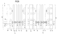
- FIG. 8 shows a partial plan view of the in Fig. 7 shown inrun track.
- the cross member 14 has holes 81, by means of which it is connected to a substructure U a ski jumping facility can be mounted.
- the cooling projections 70 are U-shaped, so that a cooling line middle part 83, which connects two cooling line legs 84, is laterally projecting into the individual tracks 72 and 74.
- the cooling line legs 84 are connected to a central manifold cooling tube (not shown) so that they are flowed through by a cooling medium during operation. These manifold cooling tubes extend along the approach direction A.
- the track edge legs 78 and 58 each extend along the input direction A and transverse to the cross members 14 upwards out of the bottom cooling line level.
- FIG. 9 shows a partial perspective view of in Fig. 7 shown inrun track.
- the track edge legs 78 are arranged in two rows so as to form two walls for defining the single track 72.
- the track edge legs 58 are arranged in two rows so that they form two walls for defining the single track 74.
- the track edge legs 58 and 78 are each arranged adjacent, so that in each case a track edge legs 58 and 78 of each row is arranged on a cross member 14.
- the track edge legs 58 and 78, each forming a wall for a track edge of the individual tracks 72 and 74 may also be integrally formed.
- the cooling projections 70 are connected to each other by means of parallel to the start-up direction A manifold manifold cooling tubes (not shown).
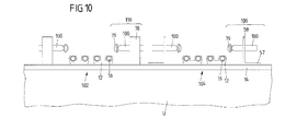
- FIG. 10 shows a schematic cross-sectional view of a run-in track with a fifth embodiment of the run-track cooling system.
- inrun track has two individual tracks 102 and 104.
- the inrun track cooling system is the same as in Fig. 7 shown run-track cooling system with the difference that the cooling projections 100 of the track edge cooling elements 106 and 116 are formed differently than those in Fig. 7 shown cooling projections.
- FIG. 11 shows a partial plan view of the in Fig. 10 shown inrun track.
- the individual tracks 102 and 104 correspond to those in FIG Fig. 8 shown individual tracks 72nd and 74 except that each cooling projection 100 is compared to that in FIG Fig. 8
- shown cooling projection 70 is also formed u-shaped, but the two cooling-line legs 84 adjacent to each other and thus the cooling line middle part 103 connecting the two cooling line legs 84 is formed in the direction of approach A much shorter.
- This design can also be realized in that in a closed to the run-in track pipe section a partition is introduced, which does not extend to the closed end of the pipe section. In this way, on the one side of the partition wall of the one cooling line legs 84 and on the other side of the partition wall of the other cooling pipe legs 84 is formed.
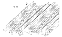
- FIG. 12 shows a partial perspective view of in Fig. 10 shown inrun track.
- the individual tracks 102 and 104 correspond to those in FIG Fig. 9 shown individual tracks 72 and 74 with the difference that each cooling projection 100 compared to the in Fig. 8 Cooling projection 70 shown two less spaced cooling line leg 84 has.
- the number of retaining elements 12, cooling pipe 10, floor cooling pipe 16 and cross members 16 is arbitrary.
Landscapes
- Engineering & Computer Science (AREA)
- Architecture (AREA)
- Civil Engineering (AREA)
- Structural Engineering (AREA)
- Physics & Mathematics (AREA)
- Mechanical Engineering (AREA)
- Thermal Sciences (AREA)
- General Engineering & Computer Science (AREA)
- Fittings On The Vehicle Exterior For Carrying Loads, And Devices For Holding Or Mounting Articles (AREA)
- Compositions Of Macromolecular Compounds (AREA)
Abstract
Description
- Die Erfindung betrifft ein Anlaufspurkühlsystem für eine Skisprungschanze.
- Es gibt unterschiedliche Varianten von Anlaufspurkühlsystemen für den Skisprungsport. In den unterschiedlichen Varianten wird unter anderem dem Umstand Rechnung getragen, dass sich die klimatischen Verhältnisse ändern, so dass die Temperaturen selbst in den Wintermonaten oftmals zu warm und zu schwankend sind, um die Ausbildung und/oder Aufrechterhaltung einer stabilen Anlaufspur zuzulassen. Insbesondere Flugschanzen werden oftmals nur für Wettkämpfe genutzt und sind daher mitunter nur wenige Tage im Jahr in Verwendung. Für solche Schanzen ist ein mobiles Anlaufspurkühlsystem wünschenswert, das nur für den benötigten Zeitraum der Nutzung montiert wird.
- Die Anlaufspur einer Skisprungschanze weist zwei Einzelspuren mit jeweils zwei Spurkanten auf. Ein Anlaufspurkühlsystem, das zur Kühlung der entlang einer Anlaufrichtung erstreckten Anlaufspur einer Skisprungschanze geeignet ist, weist beispielsweise Bodenkühlleitungen auf, die auf Querträgern fixiert sind. Eine Mehrzahl nebeneinander angeordneter Bodenkühlleitungen zur Führung eines flüssigen Kühlmediums ist entlang der Anlaufrichtung verlaufend und quer zur Anlaufrichtung betrachtet in einer gemeinsamen Bodenkühlleitungs-Ebene angeordnet. Sie sind nach oben hin frei zugänglich angeordnet, d.h. die Bodenkühlleitungen liegen frei und sind nicht durch weitere Bauelemente abgedeckt. Eine Mehrzahl entlang der Anlaufrichtung voneinander beabstandeter Querträger erstreckt sich jeweils quer zur Anlaufrichtung, wobei die Querträger zur Montage des Anlaufspurkühlsystems auf der Unterkonstruktion einer Skisprungschanze geeignet sind. Aus der
DE102008017126A1 ist ein solches Anlaufspurkühlsystem bekannt. Zur Erzeugung einer Eisschicht auf dem Anlaufspurkühlsystem werden die auf den Querträgern angeordneten kalten Bodenkühlleitungen mit Wasser besprüht, das auf den Bodenkühlleitungen schnell festfriert. Auf diese Weise kann sukzessiv eine Eisschicht ausgebildet werden. Wenn die Eisschicht eine ausreichende Dicke erreicht hat, dann können die beiden Einzelspuren eingefräst werden. Auf diese Weise wird, die Eisanlaufspur ausgebildet. Die Eisoberfläche dieser Eisanlaufspur ist von den Bodenkühlleitungen unterschiedlich weit beabstandet. Da Eis ein vergleichsweise schlechter Wärmeleiter ist, besteht trotz hoher Kühlleistung in den Bodenkühlleitungen die Gefahr, dass die Eisoberfläche zumindest in den weiter von den Bodenkühlleitungen entfernten Abschnitten z.B. bei starker Sonneneinstrahlung anschmilzt, während andere Bereiche der Eisanlaufspur gefroren bleiben. - Nachteilig an dem bekannten Anlaufspursystem ist daher insbesondere, dass die Spurkanten der Eisanlaufspur bei Benutzung strukturell instabil werden können. Dadurch ist es nicht möglich, während eines Wettkampfs über die Wettkampfzeitdauer gleich bleibende Bedingungen für die Wettkampfteilnehmer zu gewährleisten.
- Der vorliegenden Erfindung liegt somit die Aufgabe zu Grunde, ein Anlaufspurkühlsystem für eine Skisprungschanze bereit zu stellen, das während der Nutzung der Eisanlaufspur in einem Wettkampf strukturell stabilere Spurkanten in den Einzelspuren aufweist.
- Diese Aufgabe wird durch ein Anlaufspurkühlsystem mit den Merkmalen des Anspruchs 1 gelöst.
- Erfindungsgemäß ist vorgesehen, dass zur Bildung der Spurkanten der Anlaufspur zwischen den Bodenkühlleitungen und/oder benachbart zu den Bodenkühlleitungen strukturell voneinander getrennt ausgebildete Spurkanten-Kühlelemente angeordnet sind, die jeweils aus der Bodenkühlleitungs-Ebene nach oben herausragen und sich jeweils parallel zur Anlaufrichtung erstrecken und dass die Spurkanten-Kühlelemente aus einem Material mit einem Wärmeleitkoeffizienten von mehr als 10 W/m°K gebildet sind. Dadurch wird ein struktureller Aufbau realisiert, der einen in etwa gleich bleibenden geringen Abstand zwischen der Eisoberfläche und den insbesondere die Eisoberfläche kühlenden Bauelementen in Form der Bodenkühlleitungen und der Spurkanten-Kühlelemente aufweist. Dadurch wird eine gleichmäßigere Kühlung der Eisanlaufspur erreicht. Ein weiterer Vorteil dieses Anlaufspurkühlsystems besteht darin, dass es sich auf einfache Weise als mobiles System ausbilden lässt. Es kann daher mit vertretbarem Arbeitsaufwand bei Bedarf für eine Wettkampfveranstaltung auf- und danach wieder abgebaut werden. Zudem stellt ein Material mit einem derartigen Wärmeleitkoeffizienten für die Spurkanten-Kühlelemente zusammen mit den Bodenkühlleitungen eine ausreichende Kühlung der Anlaufspur entlang ihrer gesamten Oberfläche sicher.
- Der Wärmeleitkoeffizient kann nach DIN 22007 ggf. analog bestimmt werden. DIN 22007-1 bis -4 beschreiben jeweils Verfahren zur Messung der Wärmeleitfähigkeit von polymeren Kunststoffen in Abhängigkeit des Anwendungsbereiches bzw. des Messverfahrens. Die Verfahren können ggf. analog auf andere Materialien und Wärmeleitkoeffizienten angewendet werden. Die Wärmeleitfähigkeit ist mit einem im Handel erhältlichen Plattengerät (hot plate) zu bestimmen.
- Die Spurkanten-Kühlelemente ragen bevorzugt mehr als zwei besonders bevorzugt mehr als vier Zentimeter über die Bodenkühlleitungs-Ebene nach oben heraus.
- Mit Hilfe eines solchen Anlaufspursystems kann man schichtweise einen Eispanzer aufbauen, der keine ebene Fläche bildet sondern zwischen den mit einer Eisschicht versehenen Spurkanten-Kühlelementen Vertiefungen aufweist. In diesen Eispanzer lassen sich dann die beiden Einzelspuren einfräsen, so dass eine Natur-Eisspur in Form mit Eis bedeckter u-förmiger Einzelspuren gebildet wird. Dabei sind die Bodenkühlleitungen mit Eis bedeckt und auf den Spurkanten-Kühlelementen sind Spurkanten aus Eis gebildet. Bevorzugt ist die Eisschicht der Anlaufspur weniger als 3cm besonders bevorzugt zirka 2cm stark. Das heißt der Abstand der Anlaufspuroberfläche, die auch bei Umgebungstemperaturen über dem Gefrierpunkt und bei Sonneneinstrahlung auf weniger als null Grad gehalten werden muss, zu den die Kühlleistung in die Eisschicht eintragenden Bauelementen ist in Querschnitt des Anlaufspursystems betrachtet gleichmäßig minimiert.
- In einer bevorzugten Ausführungsform sind die Spurkanten-Kühlelemente aus einem Material mit einem Wärmeleitkoeffizienten von mehr als 50 W/m°K und bevorzugt mehr als 100 W/m°K gebildet. Ein Material mit den vorstehenden Wärmeleitkoeffizienten stellt einen ausreichenden Transport an thermischer Energie zwischen den Spurkanten-Kühlelementen und der Oberfläche der Anlaufspur sicher. Eine Wärmeleitfähigkeit von mehr als 10 W/m°K weisen beispielsweise sämtliche Metalle und Metalllegierungen auf. Von den klassischen Nicht-Metallen wäre Graphit ein geeigneter Werkstoff. Üblicherweise wird das Kühlelement jedoch aus metallischen Werkstoffen aufgebaut sein. Die höchste thermische Leitfähigkeit bei vergleichsweise überschaubaren Material- und Herstellungskosten bietet Aluminium. Das Kühlelement lässt sich besonders wirtschaftlich als einstückiges Aluminium-L-Profil ausbilden. Auch die Verwendung von Stahl, insbesondere Edelstahl, ist wirtschaftlich. Vorzugsweise werden die metallischen Materialien in Form eines Blechs eingesetzt. Alternativ kann vorzugsweise ein mit Kohlenstoff versehener Kunststoff oder eine Keramik mit einem entsprechenden Wärmeleitkoeffizienten als Material in Frage kommen.
- Vorzugsweise weisen die Spurkanten-Kühlelemente quer zur Anlaufrichtung betrachtet einen parallel zu den Querträgern orientierten Montageschenkel und einen nach oben aus der Bodenkühlleitungs-Ebene herausragenden Spurkanten-Schenkel auf. Dies lässt sich im einfachsten Fall durch ein L-Profil realisieren. Auch andere Profilformen wie T- oder U-Profile sind einsetzbar, soweit immer ein Montageschenkel und ein aus der Bodenkühlleitungs-Ebene herausragender Spurkanten-Schenkel ausgebildet sind.
- Der zu den Querträgern parallel orientierte Montageschenkel ist vorzugsweise mit den Querträgern verbindbar. Beispielsweise sind Querträger und zu den Querträgern orientierte Montageschenkel jeweils mittels mindestens einer Schraubverbindung aneinander befestigt. Die Montageschenkel sind vorzugsweise derart angeordnet, dass sie von den Bodenkühlleitungen weg weisen und auf den Montageschenkeln keine Bodenkühlleitungen verlaufen.
- In einer bevorzugten Ausführungsform sind neben den Bodenkühlleitungen Spurkanten-Kühlleitungen vorgesehen, die oberhalb der Bodenkühlleitungs-Ebene an den Spurkanten-Schenkeln der Spurkanten-Kühlelemente verlaufen. Dazu ist an dem nach oben aus der Bodenkühlleitungs-Ebene herausragenden Spurkanten-Schenkel vorzugsweise mindestens ein Halteelement angeordnet, das geeignet ist, eine Spurkanten-Kühlleitung zu halten. Dadurch kann ein thermischer Kontakt zwischen den Spurkanten-Schenkeln und den Spurkanten-Kühlleitungen realisiert werden. Bei Betrieb des Anlaufspurkühlsystems werden die Spurkanten-Schenkel mittels eines durch die Spurkanten-Kühlleitungen zirkulierendes Kühlmedium gekühlt. Die Bodenkühlleitungen und Spurkanten-Kühlleitungen können miteinander verbunden sein, so dass ein Kühlmedium durch sie förderbar ist und nur eine Pumpe zum Fördern des Kühlmediums benötigt wird. Die Spurkanten-Kühlleitungen sind vorzugsweise jeweils mittels Haltelementen mit den Spurkanten-Schenkeln verbunden. Die Halteelemente sind jeweils mit den Spurkanten-Schenkeln mittels Schraubverbindungen befestigt und strukturell so ausgebildet, dass eine Spurkanten-Kühlleitung mittels Einsteckens befestigbar ist. Vorzugsweise sind die Spurkanten-Kühlleitungen und/oder die Bodenkühlleitungen miteinander mäanderförmig verbunden. In einer bevorzugten Ausführungsform bilden die Spurkanten-Kühlleitungen und/oder die Bodenkühlleitungen ein Kühlleitungssystem, durch das ein Kühlmedium förderbar ist. Die Spurkanten-Kühlleitungen können an der der zugehörigen Einzelspur zugewandten Seite des Spurkanten-Schenkels angeordnet sein. Alternativ oder zusätzlich können sie an der der zugehörigen Einzelspur abgewandten Seite des Spurkanten-Schenkels angeordnet sein.
- Vorzugsweise weist mindestens einer der Spurkanten-Schenkel Kühlvorsprünge auf, die sich quer zur Anlaufrichtung in Richtung der zugehörigen Einzelspur erstrecken. Das Merkmal "Kühlvorsprünge" im Sinne der Erfindung umfasst jede Struktur, die ausgehend vom Spurkanten-Schenkel zumindest abschnittsweise in die Einzelspur hinein ragt. Darunter ist auch eine Kühlleitung zu verstehen, die parallel zu dem Spurkanten-Schenkel verläuft, an dem sie montiert ist, da sie einen Vorsprung relativ zu dem Spurkanten-Schenkel darstellt. Das Merkmal Kühlvorsprünge beinhaltet aber auch eine Mehrzahl an Einzelvorsprüngen, die sich quer zur Anlaufrichtung und in Richtung der zugehörigen Einzelspur erstrecken, und zur abschnittsweisen Kühlung der Eises der Anlaufspur im Bereich der Spurkanten-Schenkel geeignet sind. Für alle Ausführungsformen der Kühlvorsprünge gilt, dass dadurch eine besonders gute strukturell-mechanische Verankerung der die Anlaufspurkanten bildenden Eisschichten am Anlaufspursystem erzielt wird.
- Bevorzugt sind die Kühlvorsprünge ausgehend vom Spurkanten-Schenkel u-förmig ausgebildet. Bei dieser Ausgestaltung können die Kühlvorsprünge als Leitungsrohrabschnitte abzweigend von den Spurkanten-Kühlleitungen angeordnet sein. Alternativ gehen benachbarte Kühlvorsprünge mäanderförmig ineinander über.
- In einer bevorzugten Ausführungsform sind die Kühlvorsprünge als Leitungsabschnitte für das Kühlmedium des Anlaufspurkühlsystem ausgebildet. D.h. die Kühlvorsprünge sind Teil eines Kühlleitungssystems. Vorzugsweise sind die Kühlvorsprünge, die Spurkanten-Kühlleitungen und die Bodenkühlleitungen miteinander verbunden, so dass durch sie ein Kühlmedium fließt und sie alle mit einer Pumpe verbunden sind, die bei Betrieb das Kühlmedium umwälzt.
- In einer weiteren bevorzugten Ausführungsform sind die Kühlvorsprünge einstückig mit dem zugehörigen Spurkanten-Schenkel ausgebildet. Dadurch wird eine besonders gute Wärmeleitung zwischen den Spurkanten-Schenkeln und den sich einstückig aus diesen herausgebildeten Kühlvorsprüngen gewährleistet. Außerdem ermöglicht diese Variante, die Montagezeit beim Auf- und Abbau des Anlaufspurkühlsystems zu reduzieren. Wenn die Spurkanten-Schenkel aus Metall wie beispielsweise Aluminium oder Edelstahl gebildet sind, stellen die Kühlvorsprünge Metallabschnitte des Spurkanten-Schenkels dar, die aus der Erstreckungsebene des Spurkanten-Schenkels herausgebogen sind.
- Vorzugsweise sind an Endabschnitten der Kühlvorsprünge, die von den Spurkanten-Schenkeln maximal beabstandet sind, Gleitelemente angeordnet. Als Werkstoff für die Gleitelemente eignet sich insbesondere eine Keramik oder ein Kunststoff. Von den Keramik-Werkstoffen weist insbesondere Porzellan vorteilhafte Eigenschaften auf. Die Gleitelemente weisen Gleiteigenschaften für Skier auf, die denen von Eis entsprechen. Dadurch wird sichergestellt, dass auch bei unvollständiger Vereisung der Kühlvorsprünge an den Endabschnitten Benutzern der Eisanlaufspur hervorragende Gleiteigenschaften bereitgestellt werden. Die Gleitelemente sind vorzugsweise derart dimensioniert, dass sie durch einfaches Aufstecken an den Kühlvorsprüngen befestigbar sind.
- In einer bevorzugten Ausführungsform ist im oberen Bereich über dem Spurkanten-Schenkel ein Spurkantengleitelement aus Kunststoff oder aus Keramik angeordnet. Die Spurkantengleitelemente erstrecken sich parallel zur Anlaufrichtung und bilden in der Einzelspur die Gleitkanten, an denen Kanten der Skier eines Springers abgleiten. Um die Reibungsfläche zwischen Ski-Kante und Spurkantengleitelement zu minimieren, sind die Spurkantengleitelemente in Richtung auf die zur Bodenkühlleitungsebene betrachtet mit einem geringfügigen Hinterschnitt angeordnet. Die Spurkanten-Gleitelemente weisen Gleiteigenschaften für die Kanten von Skiern auf, die mit denen von Eis vergleichbar sind. Daher ist eine Ausbildung von Eis auf den Spurkanten-Gleitelementen nicht erforderlich. Vielmehr ist es in dieser Ausführungsform ausreichend, wenn die Anlaufspurkühlung ausgelegt ist, auf dem Boden der ausgebildeten und durch die Anlaufspurkühlung gekühlten Einzelspur und nicht an deren Spurkanten Eis zu bilden. Das Spurkanten-Gleitelement ist vorzugsweise derart ausgebildet, dass es auf das jeweilige Spurkanten-Kühlelement vorzugsweise den jeweiligen Spurkanten-Schenkel aufsteckbar ist. Die Spurkanten-Gleitelemente sind vorzugsweise jeweils so dimensioniert, dass sie sich in der Einzelspur bei Benutzung der Anlaufspurkühlung in Richtung zu dem Montageschenkel derart erstrecken, dass sie zumindest teilweise unterhalb des Eises liegen, das auf dem Boden der Einzelspur gebildet ist.
- In einer bevorzugten Ausführungsform sind die u-förmigen Kühlvorsprünge jeweils aus einem Rohr ausgebildet, in das eine Trennwand eingebracht ist, so dass auf der einen Seite der Trennwand ein Kühlleitungs-Schenkel und auf der anderen Seite der Trennwand ein anderer Kühlleitungs-Schenkel ausgebildet sind, die über ein Kühlleitungs-Mittelteil miteinander verbunden sind. Die Kühlleitungs-Mittelteile bilden die Endabschnitte der Kühlvorsprünge, die von den Spurkanten-Schenkeln maximal beabstandet sind. Auf dieser Weise sind die Kühlvorsprünge leicht herstellbar und leicht montierbar.
- Vorzugsweise sind die Kühlvorsprünge durch Sammelleitungs-Kühlrohre verbunden, die parallel zur Anlaufrichtung verlaufen. In einer bevorzugten Ausführungsform bilden die Kühlvorsprünge und/oder die Bodenkühlleitungen ein Kühlleitungssystem, durch das ein Kühlmedium förderbar ist, so dass nur eine Pumpe zum Betreiben des Anlaufspur-Kühlsystems notwendig ist. Nachfolgend werden beispielhaft mögliche Ausführungsformen des Anlaufspurkühlsystems anhand der Figuren beschrieben. Gleiche oder ähnliche Bauelemente sind mit den gleichen Bezugszeichen versehen.
- Es zeigen:
- Figur 1
- eine schematische Querschnittsansicht einer Anlaufspur mit einer ersten Ausführungsform des erfindungsgemäßen Anlaufspurkühlsystems;
- Figur 2
- eine perspektivische Teilansicht der in
Fig. 1 gezeigten Anlaufspur; - Figur 3
- eine schematische Querschnittsansicht einer Anlaufspur mit einer zweiten Ausführungsform des Anlaufspurkühlsystem;
- Figur 4
- eine perspektivische Teilansicht der in
Fig. 3 gezeigten Anlaufspur; - Figur 5
- eine schematische Querschnittsansicht einer Anlaufspur mit einer dritten Ausführungsform des Anlaufspurkühlsystems;
- Figur 6
- eine perspektivische Teilansicht der in
Fig. 5 gezeigten Anlaufspur; - Figur 7
- eine schematische Querschnittsansicht einer Anlaufspur mit einer vierten Ausführungsform des Anlaufspurkühlsystems;
- Figur 8
- eine Teildraufsicht auf die in
Fig. 7 gezeigte Anlaufspur; - Figur 9
- eine perspektivische Teilansicht der in
Fig. 7 gezeigten Anlaufspur; - Figur 10
- eine schematische Querschnittsansicht einer Anlaufspur mit einer fünften Ausführungsform des Anlaufspurkühlsystem;
- Figur 11
- eine Teildraufsicht auf die in
Fig. 10 gezeigte Anlaufspur; und - Figur 12
- eine perspektivische Teilansicht der in
Fig. 10 gezeigten Anlaufspur. -
Figur 1 zeigt eine schematische Querschnittsansicht einer Anlaufspur mit einer ersten Ausführungsform des Anlaufspurkühlsystems. Die Anlaufspur weist zwei Einzelspuren 2 und 4 auf. Diese verlaufen senkrecht zur Schnittebene entlang einer in dieser Darstellung nicht gezeigten Anlaufrichtung A. Der Übersichtlichkeit halber ist bei der Einzelspur 2 das Anlaufspurkühlsystem nur teilweise gezeigt, während bei der Einzelspur 4 das komplett aufgebaute Anlaufspurkühlsystem gezeigt ist. In der Realität sind beide Einzelspuren 2 und 4 mit jeweils dem kompletten Anlaufspurkühlsystem ausgestattet. Das Anlaufspurkühlsystem weist einen in der Querschnittsebene verlaufenden geradlinigen Querträger 14 mit daran fixierten Bodenkühlleitungen 16 auf. Die Bodenkühlleitungen 16 sind in einer gemeinsamen Bodenkühlleitungs-Ebene und nach oben hin in die Einzelspur 4 frei zugänglich angeordnet. Die Bodenkühlleitungen 16 sind an dem Querträger 14 mittels Halteelementen 12 beispielsweise durch Einstecken befestigt. Die Querträger 14 sind zur Montage des Anlaufspurkühlsystems auf einer Unterkonstruktion U einer Skisprungschanze geeignet. Das Anlaufspurkühlsystem weist weiterhin zwei Spurkanten-Kühlelemente 6 auf. Diese Spurkanten-Kühlelemente 6 erstrecken sich im Wesentlichen senkrecht von den Querträgern 14 nach oben. Die Spurkanten-Kühlelemente 6 weisen jeweils einen Spurkanten-Schenkel 8 auf, der sich ebenfalls aus der Bodenkühlleitungs-Ebene nach oben hin weg erstreckt. An jedem Spurkanten-Schenkel 8 der Einzelspur 4 sind Spurkanten-Kühlleitungen 10 angeordnet, die bei dieser Ausführungsform an der der Einzelspur 4 zugewandten Seite des Spurkanten-Schenkels 8 angeordnet sind und durch die bei Betrieb des Anlaufspurkühlsystems ein Kühlmedium fließt. Die Kühlleitungen 10 sind mittels Halteelementen 12 an den Spurkanten-Schenkeln 8 befestigt. Die Spurkanten-Schenkel 8 sind auf den Querträger 14 aufgesteckt. Die Einzelspur 2 ist der Anschaulichkeit halber nur mit ihren zwei Spurkanten-Schenkeln 8 gezeigt, die auf den Querträger 14 gesteckt sind, wobei die Bodenkühlleitungen 16, die Spurkanten-Kühlleitungen 10 und die Halteelemente 12 nicht gezeigt sind. Die Spurkanten-Kühlelemente 6 sind benachbart zu den Bodenkühlleitungen 16 strukturell voneinander getrennt angeordnet und bilden daher voneinander unabhängige Baugruppen, die sich einzeln montieren und demontieren lassen. Sie ragen jeweils aus der Bodenkühlleitungs-Ebene nach oben heraus. - Bei Inbetriebnahme des in
Fig. 1 gezeigten Anlaufspurkühlsystems wird bei kompletter Ausstattung der Einzelspuren 2 und 4 Wasser auf das Anlaufspurkühlsystem beispielsweise in Form eines Sprühnebels aufgebracht, das bei Betrieb des Anlaufspurkühlsystems d.h. beim Fördern eines Kühlmediums durch die Spurkanten-Kühlleitungen 10 und die Bodenkühlleitungen 16 an diesen Leitungen anfriert. Auf diese Weise kann man schichtweise einen Eispanzer aufbauen, der keine ebene Fläche bildet sondern zwischen den mit einer Eisschicht versehenen Spurkanten-Kühlelementen 6 Vertiefungen aufweist. In diesen Eispanzer lassen sich dann die beiden Einzelspuren 2 und 4 einfräsen, so dass eine Natur-Eisspur in Form mit Eis bedeckter u-förmiger Einzelspuren 2 und 4 gebildet wird. Dabei sind die Bodenkühlleitungen 16 mit Eis bedeckt und auf den Spurkanten-Kühlelementen 6 sind Spurkanten aus Eis gebildet. -
Figur 2 zeigt eine perspektivische Teilansicht der inFig. 1 gezeigten Anlaufspur. Die Spurkanten-Kühlleitungen 10 und die Bodenkühlleitungen 16 verlaufen entlang der Anlaufrichtung A. Die Querträger 14 sind in einem vorbestimmten Abstand parallel zueinander angeordnet und verlaufen quer zur Anlaufrichtung A. Jeder der Querträger 14 ist mit vier Spurkanten-Schenkeln 8 versehen, die zur Bildung der Einzelspuren 2 und 4 in einem vorbestimmten Abstand zueinander angeordnet sind. Die Spurkanten-Schenkel 8 weisen Abmessungen und Steckeinrichtungen auf, so dass sie auf die Querträger 14 steckbar oder anderweitig fixierbar sind. Zwischen parallel zueinander angeordneten Spurkanten-Schenkeln 8, die auf benachbarten Querträgern 14 angeordnet sind, ist ein vorbestimmter Abstand ausgebildet. Die Spurkanten-Schenkel 8 weisen senkrecht zur Anlaufrichtung ein u-förmiges Profil auf, das ein einfaches Aufstecken auf den Querträger 14 ermöglicht. Ein Mittelteil 18 der Spurkanten-Schenkel 8, der die beiden Enden 19 der u-Form miteinander verbindet, ist jeweils zu der Einzelspur 2 bzw. 4 ausgerichtet. An dem Mittelteil 18 ist jeweils ein Halteelement 12 angeordnet, in die jeweils die Spurkanten-Kühlleitungen 10 eingesteckt sind, wie es in Bezug auf die Einzelspur 4 gezeigt ist. Wie in Bezug auf die Einzelspur 4 gezeigt ist, weisen sowohl die Mittelteile 18 als auch die Querträger 14 jeweils mindestens eine Ausnehmung 20 auf, die geeignet ist, ein Steckelement (nicht gezeigt) des jeweiligen Halteelements 12 aufzunehmen. Die Querträger 14 sind jeweils ebenfalls u-förmig ausgebildet. Mittelteile 22 der Querträger 14, die jeweils die beiden Enden der u-Form verbinden, sind zu den Einzelspuren 2 bzw. 4 ausgerichtet. Durch ihre Ausgestaltung können die Querträger 14 leicht an eine Unterkonstruktion (nicht gezeigt) einer Skisprunganlage montiert werden. -
Figur 3 zeigt eine schematische Querschnittsansicht einer Anlaufspur mit einer zweiten Ausführungsform des Anlaufspurkühlsystems. Die Anlaufspur weist zwei Einzelspuren 32 und 34 auf. Der Übersichtlichkeit halber ist bei der Einzelspur 32 das Anlaufspurkühlsystem nur teilweise gezeigt, während die Einzelspur 34 mit einem kompletten Anlaufspurkühlsystem ausgestattet ist. In der Realität sind beide Einzelspuren 32 und 34 mit jeweils dem kompletten Anlaufspurkühlsystem ausgestattet. Das Anlaufspurkühlsystem weist jeweils an den äußeren Spurkanten einen äußeren Spurkanten-Schenkel 38 als äußere Begrenzung der Einzelspuren 32 und 34 sowie zwischen den beiden Einzelspuren einen für beide Einzelspuren 32 und 34 gemeinsamen Spurkanten-Schenkel 37 auf. Das an der Einzelspur 34 angeordnete Anlaufspurkühlsystem weist an seiner außen angeordneten Spurkante ein Spurkanten-Kühlelement 36 auf. Das Spurkanten-Kühlelement 36 weist den äußeren Spurkanten-Schenkel 38 auf, an dem Spurkanten-Kühlleitungen 10 angeordnet sind, die in die Einzelspur 34 hinein orientiert sind und durch die bei Betrieb des Anlaufspurkühlsystems ein Kühlmedium fließt. Die Spurkanten-Kühlleitungen 10 sind mittels Halteelementen 12 an dem äußeren Spurkanten-Schenkel 38 befestigt. Der beide Einzelspuren 32 und 34 begrenzende gemeinsamer Spurkanten-Schenkel 37 ist Teil eines Spurkanten-Kühlelementes 46, der weiterhin Halteelemente 12 und Spurkanten-Kühlleitungen 10 aufweist. Das Spurkanten-Kühlelement 46 trennt die Einzelspuren 32 und 34 voneinander. Weiterhin weist das Anlaufspurkühlsystem einen Querträger 14 auf, an dem die Spurkanten-Kühlelemente 36 und 46 angeordnet ist. An dem Querträger 14 sind Bodenkühlleitungen 16 mittels Halteelementen 12 angeordnet. Die Spurkanten-Schenkel 38 und 37 erstrecken sich wiederum als strukturell voneinander unabhängige Bauelemente aus der Bodenkühlleitungsebene nach oben hin weg. Sie weisen in Richtung zu den Einzelspuren 32 und 34 jeweils eine Oberfläche auf, die in einem Winkel zu dem Querträger 14 angeordnet ist, der größer ist als 90°. Ein Halteelement 12 samt Spurkanten-Kühlleitungen 10 des Spurkanten-Kühlelementes 46 ist in Richtung zu der Einzelspur 34 orientiert. Eine Halteelement 12 samt Spurkanten-Kühlleitungen 10 des Spurkanten-Kühlelementes 46 ist parallel zu dem Querträger 14 angeordnet und geeignet, Bereiche zwischen den Einzelspuren 32 und 34 aktiv zu kühlen. -
Figur 4 zeigt eine perspektivische Teilansicht der inFig. 3 gezeigten Anlaufspur. Wie inFig. 4 ersichtlich ist, entspricht der Aufbau des gezeigten Anlaufspurkühlsystems dem inFig. 2 gezeigten Aufbau mit dem Unterschied, dass die Spurkanten-Kühlelemente 36 und 46 wie inFig. 3 gezeigt und nicht wie inFig. 1 gezeigt ausgebildet sind. Die äußeren Spurkanten-Schenkel 38 und der gemeinsame innere Spurkanten-Schenkel 37 lassen sich als einfache und preisgünstige Blechelemente ausbilden, die Fixiermittel aufweisen, um diese an den Querträgern lösbar fixieren zu können. -
Figur 5 zeigt eine schematische Querschnittsansicht einer Anlaufspur mit einer dritten Ausführungsform des Anlaufspurkühlsystems. Die inFig. 5 gezeigte Anlaufspur weist zwei Einzelspuren 52 und 54 auf. Das Anlaufspurkühlsystem entspricht dem inFig. 1 gezeigten Anlaufspurkühlsystem mit dem Unterschied, dass die Spurkanten-Kühlelemente 56 und 66 anders ausgebildet sind als die inFig. 1 gezeigten Spurkanten-Kühlelemente 6. Die Spurkanten-Kühlelemente 56 weisen Spurkanten-Schenkel 58 auf, die senkrecht zu dem Querträger 14 angeordnet sind. An der von der Einzelspur 54 abgewandten Seite der Spurkanten-Schenkel 58 ist jeweils ein Halteelement 12 angeordnet, in die Spurkanten-Kühlleitungen 10 eingesteckt sind. Jeder Spurkanten-Schenkel 58 ist einstückig mit einem parallel zu dem Querträger 14 verlaufenden Montageschenkel 57 ausgebildet, der an dem Querträger 14 mittels einer Schraub- oder Steckverbindung (nicht gezeigt) befestigt ist. Montageschenkel 57 und Spurkanten-Schenkel 58 bilden eine L-Form, wobei die auf dem Querträger 14 angebrachten Montageschenkel 57 jeweils von den Bodenkühlleitungen 16 abgewandt verlaufen. Die Einzelspur 52 ist mittels Spurkanten-Kühlelementen 66 ausgebildet, die den Spurkanten-Kühlelementen 56 entsprechen mit der Ausnahme, dass an jedem Spurkanten-Kühlelement 66 jeweils zusätzlich ein Spurkanten-Gleitelement 59 an der Seite der Spurkanten-Schenkel 58 angeordnet ist, die von den Halteelementen 12 samt Kühlleitungsrohren 10 abgewandt ist. Das Spurkanten-Gleitelement 59 ist mittels einer Steckverbindung (nicht gezeigt) an dem Spurkanten-Schenkel 58 angeordnet. Beispielsweise weist der Spurkanten-Schenkel 58 eine Ausnehmung (nicht gezeigt) auf, in die ein Vorsprung (nicht gezeigt) des Spurkanten-Gleitelements 59 gesteckt ist. -
Figur 6 zeigt eine perspektivische Teilansicht der inFig. 5 gezeigten Anlaufspur. Wie inFig. 6 ersichtlich ist, entspricht der Aufbau des gezeigten Anlaufspurkühlsystems dem inFig. 2 gezeigten Aufbau mit dem Unterschied, dass die Spurkanten-Kühlelemente 56 und 66 wie inFig. 5 gezeigt und nicht wie inFig. 1 gezeigt ausgebildet sind. Die Spurkanten-Schenkel 58 sind jeweils angrenzend zueinander angeordnet, so dass sie eine Wand entlang der Anlaufrichtung A ausbilden, wobei jeder Spurkanten-Schenkel 58 an einem Querträger 14 angeordnet ist. Die Anordnung der Spurkanten-Schenkel 58 in Form einer Wand unterstützt die Bildung des Eises bei Betrieb des Anlaufspurkühlsystems in einem definierten Bereich, weil die Einzelspuren 52 und 54 durch die wandförmig ausgebildeten Spurkanten-Schenkel 58 begrenzt sind. -
Figur 7 zeigt eine schematische Querschnittsansicht einer Anlaufspur mit einer vierten Ausführungsform des erfindungsgemäßen Anlaufspurkühlsystems. Die inFig. 7 gezeigte Anlaufspur weist zwei Einzelspuren 72 und 74 auf. Das Anlaufspurkühlsystem entspricht dem inFig. 1 gezeigten Anlaufspurkühlsystem mit dem Unterschied, dass die Spurkanten-Kühlelemente 76 und 86 anders ausgebildet sind als die inFig. 1 gezeigten Spurkanten-Kühlelemente 6. Das Spurkanten-Kühlelement 76 weist den Spurkanten-Schenkel 58 mit integral ausgebildetem Montageschenkel 57 auf, wie er in Bezug aufFig. 5 beschrieben ist. Die in Bezug aufFig. 5 beschriebene Ausnehmung des Spurkanten-Schenkels 58 ist eine Öffnung (nicht gezeigt). In der Öffnung ist eine Spurkanten-Kühlleitung in Form eines u-förmigen Kühlvorsprungs 70 aus einem Rohrabschnitt angeordnet, durch den bei Betrieb des Anlaufspurkühlsystems ein Kühlmedium strömt und der sich ausgehend von dem Spurkanten-Kühlelement 58 in die Einzelspur 74 erstreckt. An jedem Kühlvorsprung 70 ist maximal beabstandet zu dem Spurkanten-Schenkel 58 ein Gleitelement 79 angeordnet, das auf einen Endabschnitt des Kühlvorsprungs 70 aufgesteckt ist. Das Spurkanten-Kühlelement 86 entspricht dem Spurkanten-Kühlelement 76 mit dem Unterschied, dass es nicht den Spurkanten-Schenkel 58 mit integral ausgebildeten Montageschenkel 57 aufweist sondern einen Spurkanten-Schenkel 78 aufweist. Der Spurkanten-Schenkel 78 weist eine Öffnung (nicht gezeigt) auf, durch die der Kühlvorsprung 70 durchgeführt ist. Alternativ können der Kühlvorsprung 70 und der Spurkanten-Schenkel 58 und/oder 78 auch integral ausgebildet sein, wobei der Kühlvorsprung 70 dann nicht selbst von einem Kühlmedium durchflossen wird. Der integral ausgebildete Kühlvorsprung 70 wird dann über den gekühlten Spurkanten-Schenkel 58 gekühlt. Bei der hier gezeigten Ausführungsform ist der Spurkanten-Schenkel 78 auf den Querträger 14 aufgesteckt. -
Figur 8 zeigt eine Teildraufsicht auf die inFig. 7 gezeigte Anlaufspur. Der Querträger 14 weist Löcher 81 auf, mittels der er an eine Unterkonstruktion U einer Skisprunganlage montiert werden kann. Die Kühlvorsprünge 70 sind u-förmig ausgebildet, so dass ein Kühlleitungs-Mittelteil 83, das zwei Kühlleitungs-Schenkel 84 verbindet, lateral hineinragend in die Einzelspuren 72 und 74 angeordnet ist. Die Kühlleitungs-Schenkel 84 sind mit einem mittig verlaufenden Sammelleitungs-Kühlrohr (nicht gezeigt), verbunden, so dass sie bei Betrieb von einem Kühlmedium durchströmt werden. Diese Sammelleitungs-Kühlrohre verlaufen entlang der Anlaufrichtung A. Die Spurkanten-Schenkel 78 und 58 erstrecken sich jeweils entlang der Anlaufrichtung A und quer zu den Querträgern 14 nach oben hin aus der Bodenkühlleitungs-Ebene heraus. -
Figur 9 zeigt eine perspektivische Teilansicht der inFig. 7 gezeigten Anlaufspur. Die Spurkanten-Schenkel 78 sind in zwei Reihen angeordnet, so dass sie zwei Wände zur Begrenzung der Einzelspur 72 ausbilden. Genauso sind die Spurkanten-Schenkel 58 in zwei Reihen angeordnet, so dass sie zwei Wände zur Begrenzung der Einzelspur 74 ausbilden. Entlang der Anlaufrichtung A sind die Spurkanten-Schenkel 58 und 78 jeweils benachbart angeordnet, so dass jeweils ein Spurkanten-Schenkel 58 bzw. 78 jeder Reihe an einem Querträger 14 angeordnet ist. Alternativ können die Spurkanten-Schenkel 58 bzw. 78, die jeweils eine Wand für eine Spurkante der Einzelspuren 72 und 74 bilden, auch einstückig ausgebildet sein. Die Kühlvorsprünge 70 sind mittels parallel zur Anlaufrichtung A verlaufender Sammelleitungs-Kühlrohre (nicht gezeigt) miteinander verbunden. -
Figur 10 zeigt eine schematische Querschnittsansicht einer Anlaufspur mit einer fünften Ausführungsform des Anlaufspurkühlsystems. Die inFig. 10 gezeigte Anlaufspur weist zwei Einzelspuren 102 und 104 auf. Das Anlaufspurkühlsystem entspricht dem inFig. 7 gezeigten Anlaufspurkühlsystem mit dem Unterschied, dass die Kühlvorsprünge 100 der Spurkanten-Kühlelemente 106 und 116 anders ausgebildet sind als die inFig. 7 gezeigten Kühlvorsprunge. -
Figur 11 zeigt eine Teildraufsicht auf die inFig. 10 gezeigte Anlaufspur. Die Einzelspuren 102 und 104 entsprechen den inFig. 8 gezeigten Einzelspuren 72 und 74 mit der Ausnahme, dass jeder Kühlvorsprung 100 im Vergleich zu dem inFig. 8 gezeigten Kühlvorsprung 70 zwar auch u-förmig ausgebildet ist, aber die zwei Kühlleitungs-Schenkel 84 aneinander anliegend verlaufen und somit der die beiden Kühlleitungs-Schenkel 84 verbindende Kühlleitungs-Mittelteil 103 in Anlaufrichtung A betrachtet wesentlich kürzer ausgebildet ist. Diese Bauform lässt sich auch dadurch realisieren, dass in einem zur Anlaufspur hin geschlossenen Rohrabschnitt eine Trennwand eingebracht ist, die sich nicht bis zum geschlossenen Ende des Rohrabschnitts erstreckt. Auf diese Weise ist auf der einen Seite der Trennwand der eine Kühlleitungs-Schenkel 84 und auf der anderen Seite der Trennwand der andere Kühlleitungs-Schenkel 84 ausgebildet. -
Figur 12 zeigt eine perspektivische Teilansicht der inFig. 10 gezeigten Anlaufspur. Die Einzelspuren 102 und 104 entsprechen den inFig. 9 gezeigten Einzelspuren 72 und 74 mit dem Unterschied, dass jeder Kühlvorsprung 100 im Vergleich zu dem inFig. 8 gezeigten Kühlvorsprung 70 zwei geringer beabstandete Kühlleitungs-Schenkel-84 aufweist. - Die Anzahl an Halteelementen 12, Kühlleitungsrohren 10, Bodenkühlleitungsrohren 16 und Querträgern 16 ist willkürlich gewählt.
-
- A
- Anlaufrichtung
- U
- Unterkonstruktion einer Skisprungschanze
- 2
- Einzelspur
- 4
- Einzelspur
- 6
- Spurkanten-Kühlelement
- 8
- Spurkanten-Schenkel
- 10
- Kühlleitung
- 12
- Halteelement
- 14
- Querträger
- 16
- Bodenkühlleitung
- 18
- Mittelteil
- 19
- Ende
- 20
- Loch
- 22
- Mittelteil
- 24
- Ende
- 32
- Einzelspur
- 34
- Einzelspur
- 36
- Spurkanten-Kühlelement
- 37
- gemeinsamer Spurkanten-Schenkel
- 38
- äußerer Spurkanten-Schenkel
- 46
- Spurkanten-Kühlelement
- 52
- Einzelspur
- 54
- Einzelspur
- 56
- Spurkanten-Kühlelement
- 57
- Montageschenkel
- 58
- Spurkanten-Schenkel
- 59
- Spurkanten-Gleitelement
- 66
- Spurkanten-Kühlelement
- 70
- Kühlvorsprung
- 79
- Gleitelement
- 72
- Einzelspur
- 74
- Einzelspur
- 76
- Spurkanten-Kühlelement
- 78
- Spurkanten-Kühlelement
- 79
- Gleitelement
- 83
- Kühlleitungs-Mittelteil
- 84
- Kühlleitungs-Schenkel
- 86
- Spurkanten-Kühlelement
- 100
- Kühlvorsprung
- 102
- Einzelspur
- 103
- Kühlleitungs-Mittelteil
- 104
- Einzelspur
- 106
- Spurkanten-Kühlelement
- 116
- Spurkanten-Kühlelement
Claims (13)
- Anlaufspurkühlsystem zur Kühlung einer entlang einer Anlaufrichtung (A) erstreckten Anlaufspur einer Skisprungschanze, die Anlaufspur aufweisend zwei Einzelspuren (2, 4, 32, 34, 52, 54, 72, 74, 102, 104) mit jeweils zwei Spurkanten, das Anlaufspurkühlsystem aufweisend:- eine Mehrzahl nebeneinander angeordneter Bodenkühlleitungen (16) zur Führung eines flüssigen Kühlmediums, die entlang der Anlaufrichtung (A) verlaufend und quer zur Anlaufrichtung (A) betrachtet in einer gemeinsamen Bodenkühlleitungs-Ebene angeordnet sind, wobei die Bodenkühlleitungen (16) nach oben hin frei zugänglich angeordnet sind,- eine Mehrzahl entlang der Anlaufrichtung (A) voneinander beabstandeter Querträger (14), die sich jeweils quer zur Anlaufrichtung (A) erstrecken und auf denen die Bodenkühlleitungen (16) fixiert sind, wobei die Querträger (14) zur Montage des Anlaufspurkühlsystems auf einer Unterkonstruktion einer Skisprungschanze geeignet sind,dadurch gekennzeichnet, dass
zur Bildung der Spurkanten der Anlaufspur zwischen den Bodenkühlleitungen (16) und/oder benachbart zu den Bodenkühlleitungen (16) strukturell voneinander getrennt ausgebildete Spurkanten-Kühlelemente (6, 36, 46, 56, 66, 76, 86, 106, 116) angeordnet sind,
die jeweils aus der Bodenkühlleitungs-Ebene nach oben herausragen und sich jeweils parallel zur Anlaufrichtung (A) erstrecken und dass die Spurkanten-Kühlelemente (6, 36, 46, 56, 66, 76, 86, 106, 116) aus einem Material mit einem Wärmeleitkoeffizienten von mehr als 10 W/m°K gebildet sind. - Anlaufspurkühlsystem gemäß Anspruch 1, dadurch gekennzeichnet, dass die Spurkanten-Kühlelemente (6, 36, 46, 56, 66, 76, 86, 106, 116) aus einem Material mit einem Wärmeleitkoeffizienten von mehr als 50 W/m ° K und bevorzugt mehr als 100 W/m°K gebildet sind.
- Anlaufspurkühlsystem gemäß Anspruch 1 oder 2, dadurch gekennzeichnet, dass die Spurkanten-Kühlelemente (56, 66, 76, 106) quer zur Anlaufrichtung (A) betrachtet einen parallel zu den Querträgern (14) orientierten Montageschenkel (57) und einen nach oben aus der Bodenkühlleitungs-Ebene herausragenden Spurkanten-Schenkel (8, 58, 78) aufweisen.
- Anlaufspurkühlsystem gemäß Anspruch 3, dadurch gekennzeichnet, dass neben den Bodenkühlleitungen (16) Spurkanten-Kühlleitungen (10, 70, 100) vorgesehen sind, die oberhalb der Bodenkühlleitungs-Ebene an den Spurkanten-Schenkeln (8, 37, 38, 58, 78) der Spurkanten-Kühlelemente (6, 36, 46, 56, 66, 76, 86, 106, 116) verlaufen.
- Anlaufspurkühlsystem gemäß Anspruch 3 oder 4, dadurch gekennzeichnet, dass mindestens einer der Spurkanten-Schenkel (8, 37, 38, 58, 78) Kühlvorsprünge (10, 70, 100) aufweist, die sich quer zur Anlaufrichtung (A) in Richtung der zugehörigen Einzelspur (2, 4, 32, 34, 72, 74, 102, 104) erstrecken.
- Anlaufspurkühlsystem gemäß Anspruch 5, dadurch gekennzeichnet, dass die Kühlvorsprünge (70, 100) ausgehend vom Spurkanten-Schenkel (58, 78) u-förmig ausgebildet sind.
- Anlaufspurkühlsystem gemäß Anspruch 6, dadurch gekennzeichnet, dass die Kühlvorsprünge (70, 100) als Leitungsabschnitte für das Kühlmedium des Anlaufspurkühlsystem ausgebildet sind.
- Anlaufspurkühlsystem gemäß einem der Ansprüche 5 bis 7, dadurch gekennzeichnet, dass die Kühlvorsprünge einstückig mit dem zugehörigen Spurkanten-Schenkel ausgebildet sind.
- Anlaufspurkühlsystem gemäß einem der vorangehenden Ansprüche 5 bis 8, dadurch gekennzeichnet, dass an Endabschnitten der Kühlvorsprünge (70, 100), die von den Spurkanten-Schenkeln (58, 78) maximal beabstandet sind, Gleitelemente (79) angeordnet sind.
- Anlaufspurkühlsystem gemäß einem der Ansprüche 3 bis 8, dadurch gekennzeichnet, dass im oberen Bereich über dem Spurkanten-Schenkel (58) ein Spurkanten-Gleitelement (59) aus Kunststoff oder aus Keramik angeordnet ist.
- Anlaufspurkühlsystem gemäß einem der Ansprüche 6 bis 10, dadurch gekennzeichnet, dass die u-förmigen Kühlvorsprünge (100) jeweils aus einem Rohr ausgebildet sind, in das eine Trennwand eingebracht ist, so dass auf der einen Seite der Trennwand ein Kühlleitungs-Schenkel und auf der anderen Seite der Trennwand ein anderer Kühlleitungs-Schenkel ausgebildet sind, die über ein Kühlleitungs-Mittelteil miteinander verbunden sind.
- Anlaufspurkühlsystem gemäß einem der Ansprüche 5 bis 11, dadurch gekennzeichnet, dass die Kühlvorsprünge (70, 100) durch Sammelleitungs-Kühlrohre verbunden sind, die parallel zur Anlaufrichtung (A) verlaufen.
- Anlaufspurkühlsystem gemäß einem der Ansprüche 1 bis 12, dadurch gekennzeichnet, dass die Spurkanten-Kühlleitungen (10, 70, 100) und/oder die Bodenkühlleitungen (16) mäanderförmig miteinander verbunden sind.
Applications Claiming Priority (1)
| Application Number | Priority Date | Filing Date | Title |
|---|---|---|---|
| DE102014104311 | 2014-03-27 |
Publications (3)
| Publication Number | Publication Date |
|---|---|
| EP2927624A2 true EP2927624A2 (de) | 2015-10-07 |
| EP2927624A3 EP2927624A3 (de) | 2015-10-28 |
| EP2927624B1 EP2927624B1 (de) | 2019-09-04 |
Family
ID=53051717
Family Applications (1)
| Application Number | Title | Priority Date | Filing Date |
|---|---|---|---|
| EP15161076.3A Active EP2927624B1 (de) | 2014-03-27 | 2015-03-26 | Anlaufspurkühlsystem für eine Skisprungschanze |
Country Status (1)
| Country | Link |
|---|---|
| EP (1) | EP2927624B1 (de) |
Cited By (1)
| Publication number | Priority date | Publication date | Assignee | Title |
|---|---|---|---|---|
| US10835807B2 (en) | 2017-06-09 | 2020-11-17 | Dreamsbig, Llc | Liquid cooling system for outdoor surfaces |
Citations (1)
| Publication number | Priority date | Publication date | Assignee | Title |
|---|---|---|---|---|
| DE102008017126A1 (de) | 2008-04-03 | 2009-10-08 | Anlagenbau Haas Gmbh | Skisprungschanze und Verfahren zur Erzeugung einer Anlaufspur |
Family Cites Families (2)
| Publication number | Priority date | Publication date | Assignee | Title |
|---|---|---|---|---|
| EP1283399A1 (de) * | 2001-08-09 | 2003-02-12 | Axima Refrigeration GmbH | Einrichtung und Verfahren für eine Skischanze zum Aufbringen einer Eisdecke |
| DE10323250B4 (de) * | 2003-05-22 | 2005-07-28 | Angelika Riedel | Anlaufspur für Skisprungschanzen |
-
2015
- 2015-03-26 EP EP15161076.3A patent/EP2927624B1/de active Active
Patent Citations (1)
| Publication number | Priority date | Publication date | Assignee | Title |
|---|---|---|---|---|
| DE102008017126A1 (de) | 2008-04-03 | 2009-10-08 | Anlagenbau Haas Gmbh | Skisprungschanze und Verfahren zur Erzeugung einer Anlaufspur |
Cited By (1)
| Publication number | Priority date | Publication date | Assignee | Title |
|---|---|---|---|---|
| US10835807B2 (en) | 2017-06-09 | 2020-11-17 | Dreamsbig, Llc | Liquid cooling system for outdoor surfaces |
Also Published As
| Publication number | Publication date |
|---|---|
| EP2927624A3 (de) | 2015-10-28 |
| EP2927624B1 (de) | 2019-09-04 |
Similar Documents
| Publication | Publication Date | Title |
|---|---|---|
| DE19815047B4 (de) | Anordnung zur schraubenlosen Verbindung von Gitterkabelbahnen | |
| DE1478168A1 (de) | Laenglicher Koerper,insbesondere Ski,und Verfahren zur AEnderung seiner Biegsamkeit | |
| EP1479986B1 (de) | Anlaufspur für Skisprungschanzen | |
| DE1908825C3 (de) | Elektrisches Gerät mit thermisch hochbelasteten elektrischen Bauelementen und mit Kühlleitungen für ein gasförmiges Kühlmedium | |
| DE102004023086B4 (de) | Gleitflächenelement für Schisprunganlagen | |
| EP2927624B1 (de) | Anlaufspurkühlsystem für eine Skisprungschanze | |
| DE1601018C3 (de) | Kühlanordnung | |
| DE102007060755A1 (de) | Gleitflächenelement für Schisprunganlagen | |
| DE3425019A1 (de) | Bodenplatte fuer einen aufgestaenderten boden und aus solchen bodenplatten gebildeter boden | |
| DE19513201C1 (de) | Tropfenabscheider für eine dezentrale Heizungs-, Lüftungs- und/oder Kühlvorrichtung | |
| DE102008017126A1 (de) | Skisprungschanze und Verfahren zur Erzeugung einer Anlaufspur | |
| DE7537646U (de) | Anordnung zum befestigen von wand- oder deckenverkleidungen | |
| DE202004007490U1 (de) | Gleitflächenelement für Schisprunganlagen | |
| DE202007017583U1 (de) | Gleitflächenelement für Schisprunganlagen | |
| DE102012017007A1 (de) | Umhausung | |
| DE19843901C2 (de) | Verfahren zur Haltbarmachung von Schnee und Kühlmatteneinrichtung zur Durchführung des Verfahrens | |
| DE102008019794B3 (de) | Stromsammelschienenvorrichtung | |
| DE102015015357A1 (de) | Plattenlager für schwimmend verlegte Steinplatten | |
| DE3919472A1 (de) | Fuehrungsvorrichtung fuer einen langlaufski und eine dieser vorrichtung zugeordnete schuhsohle | |
| EP2902081A1 (de) | Anlaufspursystem für eine Skisprungschanze | |
| EP2650436B1 (de) | Sprungschanzenaufbau | |
| DE19852590C2 (de) | Zellenhalter zur Montage von Zellen zur elektrochemischen Speicherung von Energie zu einem Zellenblock und seine Verwendung | |
| DE29817972U1 (de) | Gehäuse zur wärmedämmenden Umhüllung von Rohrabschnitten einer Wärme- oder Kälteversorgungsanlage | |
| DE579993C (de) | Kuenstliche Eisbahn | |
| EP1772591B1 (de) | Vorrichtung für Feuerschutzisolierung |
Legal Events
| Date | Code | Title | Description |
|---|---|---|---|
| PUAL | Search report despatched |
Free format text: ORIGINAL CODE: 0009013 |
|
| PUAI | Public reference made under article 153(3) epc to a published international application that has entered the european phase |
Free format text: ORIGINAL CODE: 0009012 |
|
| AK | Designated contracting states |
Kind code of ref document: A2 Designated state(s): AL AT BE BG CH CY CZ DE DK EE ES FI FR GB GR HR HU IE IS IT LI LT LU LV MC MK MT NL NO PL PT RO RS SE SI SK SM TR |
|
| AX | Request for extension of the european patent |
Extension state: BA ME |
|
| AK | Designated contracting states |
Kind code of ref document: A3 Designated state(s): AL AT BE BG CH CY CZ DE DK EE ES FI FR GB GR HR HU IE IS IT LI LT LU LV MC MK MT NL NO PL PT RO RS SE SI SK SM TR |
|
| AX | Request for extension of the european patent |
Extension state: BA ME |
|
| RIC1 | Information provided on ipc code assigned before grant |
Ipc: E01C 13/12 20060101ALI20150923BHEP Ipc: F25C 3/04 20060101AFI20150923BHEP Ipc: A63C 19/10 20060101ALI20150923BHEP |
|
| 17P | Request for examination filed |
Effective date: 20160428 |
|
| RBV | Designated contracting states (corrected) |
Designated state(s): AL AT BE BG CH CY CZ DE DK EE ES FI FR GB GR HR HU IE IS IT LI LT LU LV MC MK MT NL NO PL PT RO RS SE SI SK SM TR |
|
| STAA | Information on the status of an ep patent application or granted ep patent |
Free format text: STATUS: EXAMINATION IS IN PROGRESS |
|
| 17Q | First examination report despatched |
Effective date: 20170706 |
|
| GRAP | Despatch of communication of intention to grant a patent |
Free format text: ORIGINAL CODE: EPIDOSNIGR1 |
|
| STAA | Information on the status of an ep patent application or granted ep patent |
Free format text: STATUS: GRANT OF PATENT IS INTENDED |
|
| INTG | Intention to grant announced |
Effective date: 20190318 |
|
| GRAS | Grant fee paid |
Free format text: ORIGINAL CODE: EPIDOSNIGR3 |
|
| GRAA | (expected) grant |
Free format text: ORIGINAL CODE: 0009210 |
|
| STAA | Information on the status of an ep patent application or granted ep patent |
Free format text: STATUS: THE PATENT HAS BEEN GRANTED |
|
| AK | Designated contracting states |
Kind code of ref document: B1 Designated state(s): AL AT BE BG CH CY CZ DE DK EE ES FI FR GB GR HR HU IE IS IT LI LT LU LV MC MK MT NL NO PL PT RO RS SE SI SK SM TR |
|
| REG | Reference to a national code |
Ref country code: GB Ref legal event code: FG4D Free format text: NOT ENGLISH |
|
| REG | Reference to a national code |
Ref country code: CH Ref legal event code: EP |
|
| REG | Reference to a national code |
Ref country code: AT Ref legal event code: REF Ref document number: 1175940 Country of ref document: AT Kind code of ref document: T Effective date: 20190915 |
|
| REG | Reference to a national code |
Ref country code: DE Ref legal event code: R096 Ref document number: 502015010207 Country of ref document: DE |
|
| REG | Reference to a national code |
Ref country code: IE Ref legal event code: FG4D Free format text: LANGUAGE OF EP DOCUMENT: GERMAN |
|
| REG | Reference to a national code |
Ref country code: NL Ref legal event code: MP Effective date: 20190904 |
|
| REG | Reference to a national code |
Ref country code: LT Ref legal event code: MG4D |
|
| PG25 | Lapsed in a contracting state [announced via postgrant information from national office to epo] |
Ref country code: LT Free format text: LAPSE BECAUSE OF FAILURE TO SUBMIT A TRANSLATION OF THE DESCRIPTION OR TO PAY THE FEE WITHIN THE PRESCRIBED TIME-LIMIT Effective date: 20190904 Ref country code: FI Free format text: LAPSE BECAUSE OF FAILURE TO SUBMIT A TRANSLATION OF THE DESCRIPTION OR TO PAY THE FEE WITHIN THE PRESCRIBED TIME-LIMIT Effective date: 20190904 Ref country code: BG Free format text: LAPSE BECAUSE OF FAILURE TO SUBMIT A TRANSLATION OF THE DESCRIPTION OR TO PAY THE FEE WITHIN THE PRESCRIBED TIME-LIMIT Effective date: 20191204 Ref country code: NO Free format text: LAPSE BECAUSE OF FAILURE TO SUBMIT A TRANSLATION OF THE DESCRIPTION OR TO PAY THE FEE WITHIN THE PRESCRIBED TIME-LIMIT Effective date: 20191204 Ref country code: SE Free format text: LAPSE BECAUSE OF FAILURE TO SUBMIT A TRANSLATION OF THE DESCRIPTION OR TO PAY THE FEE WITHIN THE PRESCRIBED TIME-LIMIT Effective date: 20190904 Ref country code: HR Free format text: LAPSE BECAUSE OF FAILURE TO SUBMIT A TRANSLATION OF THE DESCRIPTION OR TO PAY THE FEE WITHIN THE PRESCRIBED TIME-LIMIT Effective date: 20190904 |
|
| PG25 | Lapsed in a contracting state [announced via postgrant information from national office to epo] |
Ref country code: GR Free format text: LAPSE BECAUSE OF FAILURE TO SUBMIT A TRANSLATION OF THE DESCRIPTION OR TO PAY THE FEE WITHIN THE PRESCRIBED TIME-LIMIT Effective date: 20191205 Ref country code: RS Free format text: LAPSE BECAUSE OF FAILURE TO SUBMIT A TRANSLATION OF THE DESCRIPTION OR TO PAY THE FEE WITHIN THE PRESCRIBED TIME-LIMIT Effective date: 20190904 Ref country code: AL Free format text: LAPSE BECAUSE OF FAILURE TO SUBMIT A TRANSLATION OF THE DESCRIPTION OR TO PAY THE FEE WITHIN THE PRESCRIBED TIME-LIMIT Effective date: 20190904 Ref country code: LV Free format text: LAPSE BECAUSE OF FAILURE TO SUBMIT A TRANSLATION OF THE DESCRIPTION OR TO PAY THE FEE WITHIN THE PRESCRIBED TIME-LIMIT Effective date: 20190904 Ref country code: ES Free format text: LAPSE BECAUSE OF FAILURE TO SUBMIT A TRANSLATION OF THE DESCRIPTION OR TO PAY THE FEE WITHIN THE PRESCRIBED TIME-LIMIT Effective date: 20190904 |
|
| PG25 | Lapsed in a contracting state [announced via postgrant information from national office to epo] |
Ref country code: EE Free format text: LAPSE BECAUSE OF FAILURE TO SUBMIT A TRANSLATION OF THE DESCRIPTION OR TO PAY THE FEE WITHIN THE PRESCRIBED TIME-LIMIT Effective date: 20190904 Ref country code: PL Free format text: LAPSE BECAUSE OF FAILURE TO SUBMIT A TRANSLATION OF THE DESCRIPTION OR TO PAY THE FEE WITHIN THE PRESCRIBED TIME-LIMIT Effective date: 20190904 Ref country code: PT Free format text: LAPSE BECAUSE OF FAILURE TO SUBMIT A TRANSLATION OF THE DESCRIPTION OR TO PAY THE FEE WITHIN THE PRESCRIBED TIME-LIMIT Effective date: 20200106 Ref country code: IT Free format text: LAPSE BECAUSE OF FAILURE TO SUBMIT A TRANSLATION OF THE DESCRIPTION OR TO PAY THE FEE WITHIN THE PRESCRIBED TIME-LIMIT Effective date: 20190904 Ref country code: NL Free format text: LAPSE BECAUSE OF FAILURE TO SUBMIT A TRANSLATION OF THE DESCRIPTION OR TO PAY THE FEE WITHIN THE PRESCRIBED TIME-LIMIT Effective date: 20190904 Ref country code: RO Free format text: LAPSE BECAUSE OF FAILURE TO SUBMIT A TRANSLATION OF THE DESCRIPTION OR TO PAY THE FEE WITHIN THE PRESCRIBED TIME-LIMIT Effective date: 20190904 |
|
| PG25 | Lapsed in a contracting state [announced via postgrant information from national office to epo] |
Ref country code: SM Free format text: LAPSE BECAUSE OF FAILURE TO SUBMIT A TRANSLATION OF THE DESCRIPTION OR TO PAY THE FEE WITHIN THE PRESCRIBED TIME-LIMIT Effective date: 20190904 Ref country code: SK Free format text: LAPSE BECAUSE OF FAILURE TO SUBMIT A TRANSLATION OF THE DESCRIPTION OR TO PAY THE FEE WITHIN THE PRESCRIBED TIME-LIMIT Effective date: 20190904 Ref country code: CZ Free format text: LAPSE BECAUSE OF FAILURE TO SUBMIT A TRANSLATION OF THE DESCRIPTION OR TO PAY THE FEE WITHIN THE PRESCRIBED TIME-LIMIT Effective date: 20190904 Ref country code: IS Free format text: LAPSE BECAUSE OF FAILURE TO SUBMIT A TRANSLATION OF THE DESCRIPTION OR TO PAY THE FEE WITHIN THE PRESCRIBED TIME-LIMIT Effective date: 20200224 |
|
| REG | Reference to a national code |
Ref country code: DE Ref legal event code: R097 Ref document number: 502015010207 Country of ref document: DE |
|
| PLBE | No opposition filed within time limit |
Free format text: ORIGINAL CODE: 0009261 |
|
| STAA | Information on the status of an ep patent application or granted ep patent |
Free format text: STATUS: NO OPPOSITION FILED WITHIN TIME LIMIT |
|
| PG2D | Information on lapse in contracting state deleted |
Ref country code: IS |
|
| PG25 | Lapsed in a contracting state [announced via postgrant information from national office to epo] |
Ref country code: DK Free format text: LAPSE BECAUSE OF FAILURE TO SUBMIT A TRANSLATION OF THE DESCRIPTION OR TO PAY THE FEE WITHIN THE PRESCRIBED TIME-LIMIT Effective date: 20190904 Ref country code: IS Free format text: LAPSE BECAUSE OF FAILURE TO SUBMIT A TRANSLATION OF THE DESCRIPTION OR TO PAY THE FEE WITHIN THE PRESCRIBED TIME-LIMIT Effective date: 20200105 |
|
| 26N | No opposition filed |
Effective date: 20200605 |
|
| PG25 | Lapsed in a contracting state [announced via postgrant information from national office to epo] |
Ref country code: SI Free format text: LAPSE BECAUSE OF FAILURE TO SUBMIT A TRANSLATION OF THE DESCRIPTION OR TO PAY THE FEE WITHIN THE PRESCRIBED TIME-LIMIT Effective date: 20190904 |
|
| PG25 | Lapsed in a contracting state [announced via postgrant information from national office to epo] |
Ref country code: MC Free format text: LAPSE BECAUSE OF FAILURE TO SUBMIT A TRANSLATION OF THE DESCRIPTION OR TO PAY THE FEE WITHIN THE PRESCRIBED TIME-LIMIT Effective date: 20190904 |
|
| REG | Reference to a national code |
Ref country code: CH Ref legal event code: PL |
|
| REG | Reference to a national code |
Ref country code: BE Ref legal event code: MM Effective date: 20200331 |
|
| PG25 | Lapsed in a contracting state [announced via postgrant information from national office to epo] |
Ref country code: LU Free format text: LAPSE BECAUSE OF NON-PAYMENT OF DUE FEES Effective date: 20200326 |
|
| PG25 | Lapsed in a contracting state [announced via postgrant information from national office to epo] |
Ref country code: LI Free format text: LAPSE BECAUSE OF NON-PAYMENT OF DUE FEES Effective date: 20200331 Ref country code: CH Free format text: LAPSE BECAUSE OF NON-PAYMENT OF DUE FEES Effective date: 20200331 Ref country code: IE Free format text: LAPSE BECAUSE OF NON-PAYMENT OF DUE FEES Effective date: 20200326 Ref country code: FR Free format text: LAPSE BECAUSE OF NON-PAYMENT OF DUE FEES Effective date: 20200331 |
|
| PG25 | Lapsed in a contracting state [announced via postgrant information from national office to epo] |
Ref country code: BE Free format text: LAPSE BECAUSE OF NON-PAYMENT OF DUE FEES Effective date: 20200331 |
|
| GBPC | Gb: european patent ceased through non-payment of renewal fee |
Effective date: 20200326 |
|
| PG25 | Lapsed in a contracting state [announced via postgrant information from national office to epo] |
Ref country code: GB Free format text: LAPSE BECAUSE OF NON-PAYMENT OF DUE FEES Effective date: 20200326 |
|
| REG | Reference to a national code |
Ref country code: AT Ref legal event code: MM01 Ref document number: 1175940 Country of ref document: AT Kind code of ref document: T Effective date: 20200326 |
|
| PG25 | Lapsed in a contracting state [announced via postgrant information from national office to epo] |
Ref country code: AT Free format text: LAPSE BECAUSE OF NON-PAYMENT OF DUE FEES Effective date: 20200326 |
|
| PG25 | Lapsed in a contracting state [announced via postgrant information from national office to epo] |
Ref country code: TR Free format text: LAPSE BECAUSE OF FAILURE TO SUBMIT A TRANSLATION OF THE DESCRIPTION OR TO PAY THE FEE WITHIN THE PRESCRIBED TIME-LIMIT Effective date: 20190904 Ref country code: MT Free format text: LAPSE BECAUSE OF FAILURE TO SUBMIT A TRANSLATION OF THE DESCRIPTION OR TO PAY THE FEE WITHIN THE PRESCRIBED TIME-LIMIT Effective date: 20190904 Ref country code: CY Free format text: LAPSE BECAUSE OF FAILURE TO SUBMIT A TRANSLATION OF THE DESCRIPTION OR TO PAY THE FEE WITHIN THE PRESCRIBED TIME-LIMIT Effective date: 20190904 |
|
| PG25 | Lapsed in a contracting state [announced via postgrant information from national office to epo] |
Ref country code: MK Free format text: LAPSE BECAUSE OF FAILURE TO SUBMIT A TRANSLATION OF THE DESCRIPTION OR TO PAY THE FEE WITHIN THE PRESCRIBED TIME-LIMIT Effective date: 20190904 |
|
| REG | Reference to a national code |
Ref country code: DE Ref legal event code: R081 Ref document number: 502015010207 Country of ref document: DE Owner name: PETER RIEDEL GMBH, DE Free format text: FORMER OWNER: PETER RIEDEL PATENT UG (HAFTUNGSBESCHRAENKT), 08340 SCHWARZENBERG, DE |
|
| PGFP | Annual fee paid to national office [announced via postgrant information from national office to epo] |
Ref country code: DE Payment date: 20260324 Year of fee payment: 12 |