EP2927397B1 - Mortise lock - Google Patents
Mortise lock Download PDFInfo
- Publication number
- EP2927397B1 EP2927397B1 EP15161596.0A EP15161596A EP2927397B1 EP 2927397 B1 EP2927397 B1 EP 2927397B1 EP 15161596 A EP15161596 A EP 15161596A EP 2927397 B1 EP2927397 B1 EP 2927397B1
- Authority
- EP
- European Patent Office
- Prior art keywords
- latch
- thrust rod
- projection
- lock
- locking bar
- Prior art date
- Legal status (The legal status is an assumption and is not a legal conclusion. Google has not performed a legal analysis and makes no representation as to the accuracy of the status listed.)
- Not-in-force
Links
- 230000000903 blocking effect Effects 0.000 claims description 3
- 238000009434 installation Methods 0.000 claims description 2
- 230000000717 retained effect Effects 0.000 claims 1
- 230000005540 biological transmission Effects 0.000 description 6
- 238000006073 displacement reaction Methods 0.000 description 1
- 230000005484 gravity Effects 0.000 description 1
- 238000012423 maintenance Methods 0.000 description 1
- 238000004519 manufacturing process Methods 0.000 description 1
Images



Classifications
-
- E—FIXED CONSTRUCTIONS
- E05—LOCKS; KEYS; WINDOW OR DOOR FITTINGS; SAFES
- E05B—LOCKS; ACCESSORIES THEREFOR; HANDCUFFS
- E05B63/00—Locks or fastenings with special structural characteristics
- E05B63/18—Locks or fastenings with special structural characteristics with arrangements independent of the locking mechanism for retaining the bolt or latch in the retracted position
-
- E—FIXED CONSTRUCTIONS
- E05—LOCKS; KEYS; WINDOW OR DOOR FITTINGS; SAFES
- E05B—LOCKS; ACCESSORIES THEREFOR; HANDCUFFS
- E05B59/00—Locks with latches separate from the lock-bolts or with a plurality of latches or lock-bolts
Definitions
- the invention relates to a mortise lock according to the preamble of claim 1.
- the latch in addition to the bolt, the latch can also be held in the retracted position without actuation of a handle which can be coupled to the lock nut.
- Such locks are used in cases where a frequent opening and closing of a door is expected.
- Such a lock was eg by the DE 20 2007 016 158 U1 known.
- an operable by the cam of the lock cylinder slide is provided which is provided with a latching projection, wherein the slide by means of a housing-fixed pin which engages in a slot of the slider, is pivotally held.
- This latching projection can be brought into engagement with a latching projection of a two-armed lever mounted in the lock housing.
- the slider further interacts with a return lever acting on the latch, which can also be actuated by the lock nut via a driver.
- the two-armed lever is pivotable about a driver by the return lever, wherein the retraction of the case, the second provided with the locking projection arm of the two-armed lever is pivoted in the direction of the slide.
- the aim of the invention is to avoid these disadvantages and to propose a lock of the type mentioned, which is characterized by a simple structure, and in which both the case and any additional locks can be controlled.
- the features of claim 2 may be provided.
- the lock cylinder in the extension direction of the bolt by a small angular amount and then pushing back the bolt when the door handle is actuated, an engagement of the change lever in the shuttle in the second receptacle, the same, whereby the case is blocked in its retracted position.
- the push rod in installation position in the vertical direction can be dispensed with a spring load on the push rod, as this is already burdened by gravity.
- Another feature of the invention is to provide the features of claim 4. This makes it possible to easily provide a backup for the push rod and thus for all associated with this additional locks.
- the bolt itself can be secured by a positional safety slide in its extended position.
- a housing 1 is provided, wherein the representation of a provided with openings for a case 2 and a bolt 3 forend was omitted.
- a lock cylinder 7 is inserted with a cam 8 in a recording.
- a lock nut 6 is provided with a receptacle 5 for a handle pin in the housing 1.
- a push rod 9 is held axially displaceable.
- the push rod is shown in its lower, the case 2 releasing position, the case 2 is pushed out due to their given by a spring bias.
- the latch 3 is shown in its extended position.
- the lock nut 6 is provided with a driving arm 10, which, as in the Fig. 2 dashed lines is indicated on the push rod 9 by pressing of the pusher, not shown, can be brought to bear and thereby the push rod 9 can be moved upwards.
- a change lever 16 is pivotally hinged above the bolt 3, which as shown in Fig. 6 and Fig. 7 can be seen, is provided with a laterally projecting projection 17.
- This projection 17 cooperates with a in the bolt 3 in the direction of movement of the push rod 9 slidably held change slide 18, which, as from Fig. 5 can be seen, held in a recess 21 of the bolt 3 and biased by a spring 22 against its lowermost position.
- the maximum pivotal movement of the change lever 16 is limited by a front and rear abutment surface on the push rod 9 below the pivot point.
- a pin 23 from the side, in a corresponding slot 25 of a transmission lever 24 (FIG. Fig. 8 ) engages, as dotted in the Fig. 2 can be seen.
- another pin 36 is laterally from the bolt 3, which cooperates with a slide 33 for securing the position of the bolt 3.
- the bolt 3 ( Fig. 5 ) has in addition to the displaceably mounted shuttle 18 and the pins 23, 36 a further projection 37 which is in the extended position of the bolt with a recess 38 of the push rod engaged and fixed in this position, whereby the push rod at the same time as a backup for Any additional locks are used.
- the transmission lever 24 has a circular segment-shaped portion 26, with which it surrounds the lock cylinder 7 partially, as from the Fig. 2 can be seen.
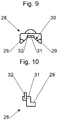
- a locking segment 28 which in the FIGS. 9 and 10 is shown.
- This has a substantially U-shaped shape, wherein the legs 29 against the center of the locking segment 28 extending inclined surfaces 30, where the cam 8 of the lock cylinder 7 engages.
- a projection 32 is formed, which is formed in a circular segment and engages in the recess 27 of the transmission lever 24.
- housing 1 further provided for securing the position of the bolt 3 slide 33 is provided which is biased by a spring 34 against its blocking position and by turning the lock cylinder by the cam 8 against the spring force can be raised, whereby the lock of the bolt 3, from the projecting with the slider 33 pin 36 projects, is repealed and this can be pushed out or withdrawn.
- the latch 3 To cancel the blockade of the case 2 (daytime function), the latch 3 must be pushed out, whereby the projection 17 of the change lever 16 is disengaged from the shuttle 18 and the push rod 9 can slide down. If the latch 3 is withdrawn again, the projection 17 comes into engagement with the first lower receptacle 20 of the shuttle 18 and can therefore be moved freely, whereby the blockage of the case 2 is released.
Landscapes
- Engineering & Computer Science (AREA)
- Structural Engineering (AREA)
- Lock And Its Accessories (AREA)
- Clamps And Clips (AREA)
Description
Die Erfindung bezieht sich auf ein Einsteckschloss gemäß dem Oberbegriff des Anspruches 1.The invention relates to a mortise lock according to the preamble of
Bei solchen Schlössern ist vorgesehen, dass neben dem Riegel auch die Falle in der zurückgezogenen Stellung ohne Betätigung einer mit der Schlossnuss koppelbaren Handhabe gehalten werden kann. Solche Schlösser werden in Fällen eingesetzt, in denen mit einem häufigen Öffnen und Schließen einer Tür zu rechnen ist.In such locks it is provided that, in addition to the bolt, the latch can also be held in the retracted position without actuation of a handle which can be coupled to the lock nut. Such locks are used in cases where a frequent opening and closing of a door is expected.
Ein solches Schloss wurde z.B. durch die
Bei diesem Schloss ist es möglich, durch Verdrehen des Schließzylinders um einen kleinen Winkelbetrag und gleichzeitiges Betätigen des Türdrückers die Rastvorsprünge des Schiebers und des zweiarmigen Hebels miteinander zu verhaken, wodurch der Schieber in einer Lage gehalten wird, in dem er den Rückzugshebel in der der zurückgezogenen Stellung der Falle entsprechenden Lage blockiert. Durch Ausschieben des Riegels mittels des Schließzylinders wird der Schieber verschwenkt und gerät außer Eingriff mit dem Rastvorsprung des zweiarmigen Hebels. Dadurch wird die Falle freigegeben und ausgeschoben.In this lock, it is possible by twisting the lock cylinder by a small angular amount and simultaneously pressing the door handle the locking projections of the slider and the two-armed lever to lock together, whereby the slider is held in a position in which he retracted the lever in the retracted Position of the trap corresponding location blocked. By pushing out the bolt by means of the lock cylinder, the slider is pivoted and disengaged from the locking projection of the two-armed lever. As a result, the trap is released and ejected.
Bei dieser Lösung ergibt sich der Nachteil einer Vielzahl von Bauteilen, die aneinander anliegen und aneinander reiben, wodurch sich eine entsprechend hohe Wartungsanfälligkeit ergibt. Außerdem eignet sich ein solches Schloss nicht für eine Mehrfachverriegelung, bei welcher auch zusätzliche Schlösser entlang der Tür in einer entsprechenden Offenstellung blockiert werden können.In this solution, there is the disadvantage of a variety of components that abut each other and rub against each other, resulting in a correspondingly high maintenance susceptibility. In addition, such a lock is not suitable for a multi-point lock, in which also additional locks along the door can be blocked in a corresponding open position.
Ziel der Erfindung ist es, diese Nachteile zu vermeiden und ein Schloss der eingangs erwähnten Art vorzuschlagen, das sich durch einen einfachen Aufbau auszeichnet, und bei dem sowohl die Falle als auch eventuelle Zusatzschlösser angesteuert werden können.The aim of the invention is to avoid these disadvantages and to propose a lock of the type mentioned, which is characterized by a simple structure, and in which both the case and any additional locks can be controlled.
Erfindungsgemäß wird dies bei einem Schloss der eingangs erwähnten Art durch die kennzeichnenden Merkmale des Anspruches 1 erreicht.According to the invention this is achieved in a lock of the type mentioned by the characterizing features of
Durch die vorgeschlagenen Maßnahmen gelingt es, das Halten der Falle in der zurückgezogenen Stellung, was häufig als Tagfunktion bezeichnet wird, mit sehr wenigen Teilen zu erreichen. Dabei kann ein solches Schloss auch für Mehrfachverriegelungen verwendet werden, da eben die Schubstange in einer der zurückgezogenen Stellung der Falle entsprechenden Position gehalten wird und damit auch die übrigen Sperrelemente einer Mehrfachverriegelung in dieser Stellung blockiert werden. Gegenüber einem im Stand der Technik bekannten Schloss müssen lediglich der Riegel mit dem Wechselschieber sowie der Wechselhebel an der Schubstange vorgesehen werden, wobei die gesamte verbleibende Schlossmechanik sowie alle Arten von über die Schubstange betätigbaren Zusatzschlössern gleich bleiben können. Dies senkt die Herstellungskosten und erhöht die Flexibilität, was die Einsatzmöglichkeiten betrifft.By the proposed measures, it is possible to achieve holding the trap in the retracted position, which is often referred to as a daytime function, with very few parts. In this case, such a lock can also be used for multiple locks, since just the push rod is held in a position corresponding to the retracted position of the case and thus the other locking elements of a multiple locking are blocked in this position. Compared to a lock known in the prior art, only the bolt with the shuttle and the change lever must be provided on the push rod, the entire remaining lock mechanism and all types of actuated via the push rod auxiliary locks can remain the same. This lowers the manufacturing costs and increases the flexibility in terms of applications.
Nach einem weiteren Merkmal der Erfindung können die Merkmale des Anspruches 2 vorgesehen sein. So kann durch ein Verdrehen des Schließzylinders in Ausschubrichtung des Riegels um einen kleinen Winkelbetrag und anschließendem Zurückschieben des Riegels bei betätigtem Türdrücker, ein Eingriff des Wechselhebels in den Wechselschieber in der zweiten Aufnahme desselben, erreicht werden, wodurch die Falle in ihrer zurückgezogenen Stellung blockiert wird. Da üblicherweise die Schubstange in Einbaulage in vertikaler Richtung verläuft kann auf eine Federbelastung der Schubstange verzichtet werden, da diese ohnehin von der Schwerkraft belastet ist.According to a further feature of the invention, the features of
Die Merkmale des Anspruches 3 ermöglichen es, bestehende Schubstangen in einfacher Weise für die zusätzliche Tagfunktion zu modifizieren.The features of
Ein weiteres Merkmal der Erfindung ist es, die Merkmale des Anspruchs 4 vorzusehen. Dadurch ist es möglich, auf einfache Art und Weise eine Rückdrücksicherung für die Schubstange und damit für alle mit dieser verbundenen Zusatzschlössern vorzusehen. Der Riegel selbst kann dabei durch einen Lagesicherungsschieber in seiner ausgeschobenen Position gesichert werden.Another feature of the invention is to provide the features of claim 4. This makes it possible to easily provide a backup for the push rod and thus for all associated with this additional locks. The bolt itself can be secured by a positional safety slide in its extended position.
Die Erfindung wird nun anhand der Zeichnung näher erläutert. Dabei zeigen:
- Die
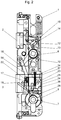
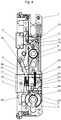
Fig. 1 bis 4 ein erfindungsgemäßes Schloss in verschiedenen Betriebszuständen, -
Fig. 5 bis 9 Detailansichten von verschiedenen Einzelteilen des Schlosses nach denFig. 1 bis 4 .
- The
Fig. 1 to 4 a lock according to the invention in various operating states, -
Fig. 5 to 9 Detail views of different items of the castle after theFig. 1 to 4 ,
Bei dem erfindungsgemäßen Schloss ist ein Gehäuse 1 vorgesehen, wobei auf die Darstellung eines mit Durchbrüchen für eine Falle 2 und einen Riegel 3 versehenen Stulps verzichtet wurde. In das Gehäuse 1 ist in einer Aufnahme ein Schließzylinder 7 mit einem Schließbart 8 eingesetzt. Weiters ist im Gehäuse 1 eine Schlossnuss 6 mit einer Aufnahme 5 für einen Drückerstift vorgesehen.In the lock according to the invention, a
Im Gehäuse 1 ist eine Schubstange 9 axial verschiebbar gehalten. In der
Die Schlossnuss 6 ist mit einem Mitnehmerarm 10 versehen, der, wie in der
Durch diese Verschiebung der Schubstange 9 kommt eine Anschlagfläche 11 derselben zur Anlage an einem Rückzugshebel 12, der um eine Achse 13 schwenkbar gehalten ist. Im Rückzugshebel 12 ist ein Bolzen 15 gelagert, der in ein Langloch 14 der Falle eingreift und diese somit zurückzieht.As a result of this displacement of the
An der Schubstange 9 ist oberhalb des Riegels 3 ein Wechselhebel 16 schwenkbar angelenkt, der wie aus der
Weiters steht von dem Riegel 3 ein Zapfen 23 seitlich ab, der in einen entsprechenden Schlitz 25 eines Übersetzungshebels 24 (
Der Riegel 3 (
Der Übersetzungshebel 24 weist einen kreissegmentförmigen Abschnitt 26 auf, mit welchem er den Schließzylinder 7 teilweise umgreift, wie aus der
In eine Ausnehmung 27 des Übersetzungshebels 24 greift ein Sperrsegment 28 ein, das in den
Wird der Schließzylinder 7 verdreht, so kommt der Schließbart 8 an dem Sperrsegment 28 zur Anlage und verschiebt dieses, wodurch auch der Übersetzungshebel 24 verdreht wird und den Riegel 3 bewegt.If the
In dem Gehäuse 1 ist weiters ein zur Lagesicherung des Riegels 3 vorgesehener Schieber 33 vorgesehen, der durch eine Feder 34 gegen seine Sperrstellung vorgespannt ist und durch Verdrehen des Schließzylinders durch den Schließbart 8 entgegen der Federkraft anhebbar ist, wodurch die Sperre des Riegels 3, von dem der mit dem Schieber 33 zusammenwirkende Zapfen 36 absteht, aufgehoben wird und dieser ausgeschoben oder zurückgezogen werden kann.In the
Wird, ausgehend von der in der
In der vollständig zurückgezogenen Stellung des Riegels 3 greift der Vorsprung 17 des Wechselhebels 16 in die erste Aufnahme 20 des Wechselschiebers 18 ein.In the fully retracted position of the
Wird nun die Schlossnuss 6 verdreht, so kommt der Mitnehmerarm 10 derselben zur Anlage an der Schubstange 9 und hebt diese an (
Wird die Falle 2 mittels des Drückers in dieser Stellung gehalten und dabei der Riegel 3 etwas ausgeschoben, so wird dabei der Schieber 33 angehoben und der Schließbart 8 verschiebt das Sperrsegment 28 und damit den Riegel 3 nach außen (
Um die Blockade der Falle 2 (Tagfunktion) aufzuheben, muss der Riegel 3 ausgeschoben werden, wodurch der Vorsprung 17 des Wechselhebels 16 außer Eingriff mit dem Wechselschieber 18 kommt und die Schubstange 9 nach unten gleiten kann. Wird der Riegel 3 wieder zurückgezogen, so kommt der Vorsprung 17 in Eingriff mit der ersten unteren Aufnahme 20 des Wechselschiebers 18 und kann daher frei bewegt werden, wodurch die Blockade der Falle 2 aufgehoben ist.To cancel the blockade of the case 2 (daytime function), the
Claims (4)
- Mortice lock having a lock cylinder (7) that comprises a lock bit (8) and actuates a locking bar (3) and can be coupled by way of a thrust rod (9) that is loaded against an end position to a spring-loaded latch (2) that can be actuated by means of a lock nut (6) and a handle, wherein a retaining mechanism is provided that in its activated position retains the latch (2) in the withdrawn position in the case of a withdrawn locking bar, characterized in that the retaining mechanism comprises a latch slider (18) that is retained in the locking bar (3) and can be displaced in the movement direction of the thrust rod (9) against the force of a resilient element, said latch slider (18) comprising two receiving arrangements (19, 20) that are spaced from one another in the movement direction of said latch slider (18) and are used to selectively support a projection (17) of a latch lever (16) that is connected in an articulated manner to the thrust rod (9), and that the projection (17) is arranged in the deactivated position of the retaining mechanism in a first receiving arrangement (20), wherein in this position the thrust rod can be displaced together with the latch lever and the latch slider, and that the projection (17) of the latch lever is supported in the activated position of the retaining mechanism in a second receiving arrangement (19) in which the thrust rod is blocked in the upper position with a withdrawn latch.
- Mortice lock according to claim 1, characterized in that in at least the half blocking position of the locking bar the projection (17) of the latch lever (16) is not in engagement with the latch slider (18), and that by means of actuating the handle and thereby the lock nut it is possible to relocate the thrust rod (9) and thereby also the latch lever (16), as a result of which it is possible to shift between the deactivated and activated position of the retaining mechanism.
- Mortice lock according to claim 1 or 2, characterized in that in the case of a thrust rod (9) that can move vertically in the installation position the latch lever (16) is connected in an articulated manner to said thrust rod (9) above the locking bar (3).
- Mortice lock according to any one of the claims 1 to 3, characterized in that the locking bar (3) comprises a projection (37) that engages in a recess (38) in the thrust rod (9) in the fully extended, blocked position of the locking bar (3) and thus blocks said thrust rod in the blocked position.
Applications Claiming Priority (1)
| Application Number | Priority Date | Filing Date | Title |
|---|---|---|---|
| ATA50240/2014A AT515800B1 (en) | 2014-04-01 | 2014-04-01 | mortise lock |
Publications (2)
| Publication Number | Publication Date |
|---|---|
| EP2927397A1 EP2927397A1 (en) | 2015-10-07 |
| EP2927397B1 true EP2927397B1 (en) | 2017-08-02 |
Family
ID=52780926
Family Applications (1)
| Application Number | Title | Priority Date | Filing Date |
|---|---|---|---|
| EP15161596.0A Not-in-force EP2927397B1 (en) | 2014-04-01 | 2015-03-30 | Mortise lock |
Country Status (2)
| Country | Link |
|---|---|
| EP (1) | EP2927397B1 (en) |
| AT (1) | AT515800B1 (en) |
Family Cites Families (5)
| Publication number | Priority date | Publication date | Assignee | Title |
|---|---|---|---|---|
| US5265920A (en) * | 1988-09-16 | 1993-11-30 | Aug. Winkaus GmbH & Co. KG | Drive rod lock |
| DE202007016158U1 (en) * | 2007-11-16 | 2008-03-20 | Bks Gmbh | lock |
| WO2010107468A1 (en) * | 2009-03-20 | 2010-09-23 | Adams Rite Manufacturing Co. | Multiple point door locking system, with handle turning direction control |
| DE202010006285U1 (en) * | 2010-04-27 | 2010-08-05 | Bks Gmbh | mortise lock |
| DE202012104831U1 (en) * | 2012-12-12 | 2014-03-13 | Maco Technologie Gmbh | Lock for a door or a window |
-
2014
- 2014-04-01 AT ATA50240/2014A patent/AT515800B1/en not_active IP Right Cessation
-
2015
- 2015-03-30 EP EP15161596.0A patent/EP2927397B1/en not_active Not-in-force
Also Published As
| Publication number | Publication date |
|---|---|
| EP2927397A1 (en) | 2015-10-07 |
| AT515800B1 (en) | 2015-12-15 |
| AT515800A4 (en) | 2015-12-15 |
Similar Documents
| Publication | Publication Date | Title |
|---|---|---|
| EP2860332B1 (en) | Self-locking lock actuated by a lever handle | |
| EP2862991B1 (en) | Locking device | |
| DE102009044657A1 (en) | Lock with panic function | |
| EP1908900A1 (en) | Lock with swivel trigger | |
| EP2862996A2 (en) | Locking device | |
| WO2016113044A1 (en) | Lock | |
| EP1031686B1 (en) | Lock with handle actuated and lockable main latch bolt | |
| DE102004013646A1 (en) | Emergency exit lock for building has spring moving bolt withdrawal lever connected to sliding bolt and includes force transmission lever | |
| DE102015000606A1 (en) | Locking device for a pivotally mounted wing | |
| DE102013001815A1 (en) | Counter box or mortise lock | |
| EP3805493A2 (en) | Modular lock with panic function | |
| DE19848865A1 (en) | Lock, especially espagnolette lock | |
| EP3215696B1 (en) | Lock | |
| EP2963213B1 (en) | Lock | |
| AT515800B1 (en) | mortise lock | |
| EP3018273B1 (en) | Additional lock | |
| EP2716844A2 (en) | Door lock | |
| DE202010006285U1 (en) | mortise lock | |
| DE102014113503A1 (en) | Lock for a locking device, in particular additional lock | |
| DE202008000676U1 (en) | lock | |
| AT516516B1 (en) | lock | |
| WO1990004694A1 (en) | Automatic lock | |
| EP3192950B1 (en) | Lock | |
| AT515775B1 (en) | lock | |
| EP0834630A2 (en) | Lock, in particular a mortise lock |
Legal Events
| Date | Code | Title | Description |
|---|---|---|---|
| PUAI | Public reference made under article 153(3) epc to a published international application that has entered the european phase |
Free format text: ORIGINAL CODE: 0009012 |
|
| AK | Designated contracting states |
Kind code of ref document: A1 Designated state(s): AL AT BE BG CH CY CZ DE DK EE ES FI FR GB GR HR HU IE IS IT LI LT LU LV MC MK MT NL NO PL PT RO RS SE SI SK SM TR |
|
| AX | Request for extension of the european patent |
Extension state: BA ME |
|
| 17P | Request for examination filed |
Effective date: 20151223 |
|
| RBV | Designated contracting states (corrected) |
Designated state(s): AL AT BE BG CH CY CZ DE DK EE ES FI FR GB GR HR HU IE IS IT LI LT LU LV MC MK MT NL NO PL PT RO RS SE SI SK SM TR |
|
| GRAP | Despatch of communication of intention to grant a patent |
Free format text: ORIGINAL CODE: EPIDOSNIGR1 |
|
| RIC1 | Information provided on ipc code assigned before grant |
Ipc: E05B 63/18 20060101ALI20160627BHEP Ipc: E05B 59/00 20060101AFI20160627BHEP |
|
| INTG | Intention to grant announced |
Effective date: 20160718 |
|
| GRAJ | Information related to disapproval of communication of intention to grant by the applicant or resumption of examination proceedings by the epo deleted |
Free format text: ORIGINAL CODE: EPIDOSDIGR1 |
|
| GRAP | Despatch of communication of intention to grant a patent |
Free format text: ORIGINAL CODE: EPIDOSNIGR1 |
|
| INTG | Intention to grant announced |
Effective date: 20170220 |
|
| GRAS | Grant fee paid |
Free format text: ORIGINAL CODE: EPIDOSNIGR3 |
|
| GRAA | (expected) grant |
Free format text: ORIGINAL CODE: 0009210 |
|
| AK | Designated contracting states |
Kind code of ref document: B1 Designated state(s): AL AT BE BG CH CY CZ DE DK EE ES FI FR GB GR HR HU IE IS IT LI LT LU LV MC MK MT NL NO PL PT RO RS SE SI SK SM TR |
|
| REG | Reference to a national code |
Ref country code: CH Ref legal event code: EP Ref country code: AT Ref legal event code: REF Ref document number: 914657 Country of ref document: AT Kind code of ref document: T Effective date: 20170815 |
|
| REG | Reference to a national code |
Ref country code: IE Ref legal event code: FG4D Free format text: LANGUAGE OF EP DOCUMENT: GERMAN |
|
| REG | Reference to a national code |
Ref country code: DE Ref legal event code: R096 Ref document number: 502015001533 Country of ref document: DE |
|
| REG | Reference to a national code |
Ref country code: DE Ref legal event code: R082 Ref document number: 502015001533 Country of ref document: DE Representative=s name: PATENTANWAELTE JECK, FLECK & PARTNER MBB, DE Ref country code: DE Ref legal event code: R082 Ref document number: 502015001533 Country of ref document: DE Representative=s name: JECK - FLECK PATENTANWAELTE, DE |
|
| REG | Reference to a national code |
Ref country code: CH Ref legal event code: NV Representative=s name: AMMANN PATENTANWAELTE AG BERN, CH |
|
| REG | Reference to a national code |
Ref country code: NL Ref legal event code: MP Effective date: 20170802 |
|
| REG | Reference to a national code |
Ref country code: LT Ref legal event code: MG4D |
|
| PG25 | Lapsed in a contracting state [announced via postgrant information from national office to epo] |
Ref country code: FI Free format text: LAPSE BECAUSE OF FAILURE TO SUBMIT A TRANSLATION OF THE DESCRIPTION OR TO PAY THE FEE WITHIN THE PRESCRIBED TIME-LIMIT Effective date: 20170802 Ref country code: NO Free format text: LAPSE BECAUSE OF FAILURE TO SUBMIT A TRANSLATION OF THE DESCRIPTION OR TO PAY THE FEE WITHIN THE PRESCRIBED TIME-LIMIT Effective date: 20171102 Ref country code: HR Free format text: LAPSE BECAUSE OF FAILURE TO SUBMIT A TRANSLATION OF THE DESCRIPTION OR TO PAY THE FEE WITHIN THE PRESCRIBED TIME-LIMIT Effective date: 20170802 Ref country code: SE Free format text: LAPSE BECAUSE OF FAILURE TO SUBMIT A TRANSLATION OF THE DESCRIPTION OR TO PAY THE FEE WITHIN THE PRESCRIBED TIME-LIMIT Effective date: 20170802 Ref country code: LT Free format text: LAPSE BECAUSE OF FAILURE TO SUBMIT A TRANSLATION OF THE DESCRIPTION OR TO PAY THE FEE WITHIN THE PRESCRIBED TIME-LIMIT Effective date: 20170802 Ref country code: NL Free format text: LAPSE BECAUSE OF FAILURE TO SUBMIT A TRANSLATION OF THE DESCRIPTION OR TO PAY THE FEE WITHIN THE PRESCRIBED TIME-LIMIT Effective date: 20170802 |
|
| PG25 | Lapsed in a contracting state [announced via postgrant information from national office to epo] |
Ref country code: IS Free format text: LAPSE BECAUSE OF FAILURE TO SUBMIT A TRANSLATION OF THE DESCRIPTION OR TO PAY THE FEE WITHIN THE PRESCRIBED TIME-LIMIT Effective date: 20171202 Ref country code: PL Free format text: LAPSE BECAUSE OF FAILURE TO SUBMIT A TRANSLATION OF THE DESCRIPTION OR TO PAY THE FEE WITHIN THE PRESCRIBED TIME-LIMIT Effective date: 20170802 Ref country code: RS Free format text: LAPSE BECAUSE OF FAILURE TO SUBMIT A TRANSLATION OF THE DESCRIPTION OR TO PAY THE FEE WITHIN THE PRESCRIBED TIME-LIMIT Effective date: 20170802 Ref country code: LV Free format text: LAPSE BECAUSE OF FAILURE TO SUBMIT A TRANSLATION OF THE DESCRIPTION OR TO PAY THE FEE WITHIN THE PRESCRIBED TIME-LIMIT Effective date: 20170802 Ref country code: GR Free format text: LAPSE BECAUSE OF FAILURE TO SUBMIT A TRANSLATION OF THE DESCRIPTION OR TO PAY THE FEE WITHIN THE PRESCRIBED TIME-LIMIT Effective date: 20171103 Ref country code: ES Free format text: LAPSE BECAUSE OF FAILURE TO SUBMIT A TRANSLATION OF THE DESCRIPTION OR TO PAY THE FEE WITHIN THE PRESCRIBED TIME-LIMIT Effective date: 20170802 Ref country code: BG Free format text: LAPSE BECAUSE OF FAILURE TO SUBMIT A TRANSLATION OF THE DESCRIPTION OR TO PAY THE FEE WITHIN THE PRESCRIBED TIME-LIMIT Effective date: 20171102 |
|
| PG25 | Lapsed in a contracting state [announced via postgrant information from national office to epo] |
Ref country code: DK Free format text: LAPSE BECAUSE OF FAILURE TO SUBMIT A TRANSLATION OF THE DESCRIPTION OR TO PAY THE FEE WITHIN THE PRESCRIBED TIME-LIMIT Effective date: 20170802 Ref country code: RO Free format text: LAPSE BECAUSE OF FAILURE TO SUBMIT A TRANSLATION OF THE DESCRIPTION OR TO PAY THE FEE WITHIN THE PRESCRIBED TIME-LIMIT Effective date: 20170802 Ref country code: CZ Free format text: LAPSE BECAUSE OF FAILURE TO SUBMIT A TRANSLATION OF THE DESCRIPTION OR TO PAY THE FEE WITHIN THE PRESCRIBED TIME-LIMIT Effective date: 20170802 |
|
| REG | Reference to a national code |
Ref country code: DE Ref legal event code: R097 Ref document number: 502015001533 Country of ref document: DE |
|
| PG25 | Lapsed in a contracting state [announced via postgrant information from national office to epo] |
Ref country code: SM Free format text: LAPSE BECAUSE OF FAILURE TO SUBMIT A TRANSLATION OF THE DESCRIPTION OR TO PAY THE FEE WITHIN THE PRESCRIBED TIME-LIMIT Effective date: 20170802 Ref country code: EE Free format text: LAPSE BECAUSE OF FAILURE TO SUBMIT A TRANSLATION OF THE DESCRIPTION OR TO PAY THE FEE WITHIN THE PRESCRIBED TIME-LIMIT Effective date: 20170802 Ref country code: IT Free format text: LAPSE BECAUSE OF FAILURE TO SUBMIT A TRANSLATION OF THE DESCRIPTION OR TO PAY THE FEE WITHIN THE PRESCRIBED TIME-LIMIT Effective date: 20170802 Ref country code: SK Free format text: LAPSE BECAUSE OF FAILURE TO SUBMIT A TRANSLATION OF THE DESCRIPTION OR TO PAY THE FEE WITHIN THE PRESCRIBED TIME-LIMIT Effective date: 20170802 |
|
| PLBE | No opposition filed within time limit |
Free format text: ORIGINAL CODE: 0009261 |
|
| STAA | Information on the status of an ep patent application or granted ep patent |
Free format text: STATUS: NO OPPOSITION FILED WITHIN TIME LIMIT |
|
| 26N | No opposition filed |
Effective date: 20180503 |
|
| PG25 | Lapsed in a contracting state [announced via postgrant information from national office to epo] |
Ref country code: SI Free format text: LAPSE BECAUSE OF FAILURE TO SUBMIT A TRANSLATION OF THE DESCRIPTION OR TO PAY THE FEE WITHIN THE PRESCRIBED TIME-LIMIT Effective date: 20170802 |
|
| PG25 | Lapsed in a contracting state [announced via postgrant information from national office to epo] |
Ref country code: MT Free format text: LAPSE BECAUSE OF FAILURE TO SUBMIT A TRANSLATION OF THE DESCRIPTION OR TO PAY THE FEE WITHIN THE PRESCRIBED TIME-LIMIT Effective date: 20170802 |
|
| PG25 | Lapsed in a contracting state [announced via postgrant information from national office to epo] |
Ref country code: MC Free format text: LAPSE BECAUSE OF FAILURE TO SUBMIT A TRANSLATION OF THE DESCRIPTION OR TO PAY THE FEE WITHIN THE PRESCRIBED TIME-LIMIT Effective date: 20170802 |
|
| REG | Reference to a national code |
Ref country code: BE Ref legal event code: MM Effective date: 20180331 |
|
| REG | Reference to a national code |
Ref country code: IE Ref legal event code: MM4A |
|
| PG25 | Lapsed in a contracting state [announced via postgrant information from national office to epo] |
Ref country code: LU Free format text: LAPSE BECAUSE OF NON-PAYMENT OF DUE FEES Effective date: 20180330 |
|
| PG25 | Lapsed in a contracting state [announced via postgrant information from national office to epo] |
Ref country code: IE Free format text: LAPSE BECAUSE OF NON-PAYMENT OF DUE FEES Effective date: 20180330 |
|
| PG25 | Lapsed in a contracting state [announced via postgrant information from national office to epo] |
Ref country code: BE Free format text: LAPSE BECAUSE OF NON-PAYMENT OF DUE FEES Effective date: 20180331 |
|
| PG25 | Lapsed in a contracting state [announced via postgrant information from national office to epo] |
Ref country code: FR Free format text: LAPSE BECAUSE OF NON-PAYMENT OF DUE FEES Effective date: 20180331 |
|
| GBPC | Gb: european patent ceased through non-payment of renewal fee |
Effective date: 20190330 |
|
| PG25 | Lapsed in a contracting state [announced via postgrant information from national office to epo] |
Ref country code: GB Free format text: LAPSE BECAUSE OF NON-PAYMENT OF DUE FEES Effective date: 20190330 |
|
| PG25 | Lapsed in a contracting state [announced via postgrant information from national office to epo] |
Ref country code: TR Free format text: LAPSE BECAUSE OF FAILURE TO SUBMIT A TRANSLATION OF THE DESCRIPTION OR TO PAY THE FEE WITHIN THE PRESCRIBED TIME-LIMIT Effective date: 20170802 |
|
| PG25 | Lapsed in a contracting state [announced via postgrant information from national office to epo] |
Ref country code: PT Free format text: LAPSE BECAUSE OF FAILURE TO SUBMIT A TRANSLATION OF THE DESCRIPTION OR TO PAY THE FEE WITHIN THE PRESCRIBED TIME-LIMIT Effective date: 20170802 |
|
| PGFP | Annual fee paid to national office [announced via postgrant information from national office to epo] |
Ref country code: CH Payment date: 20200227 Year of fee payment: 6 |
|
| PG25 | Lapsed in a contracting state [announced via postgrant information from national office to epo] |
Ref country code: MK Free format text: LAPSE BECAUSE OF NON-PAYMENT OF DUE FEES Effective date: 20170802 Ref country code: HU Free format text: LAPSE BECAUSE OF FAILURE TO SUBMIT A TRANSLATION OF THE DESCRIPTION OR TO PAY THE FEE WITHIN THE PRESCRIBED TIME-LIMIT; INVALID AB INITIO Effective date: 20150330 Ref country code: CY Free format text: LAPSE BECAUSE OF FAILURE TO SUBMIT A TRANSLATION OF THE DESCRIPTION OR TO PAY THE FEE WITHIN THE PRESCRIBED TIME-LIMIT Effective date: 20170802 |
|
| PG25 | Lapsed in a contracting state [announced via postgrant information from national office to epo] |
Ref country code: AL Free format text: LAPSE BECAUSE OF FAILURE TO SUBMIT A TRANSLATION OF THE DESCRIPTION OR TO PAY THE FEE WITHIN THE PRESCRIBED TIME-LIMIT Effective date: 20170802 |
|
| PGFP | Annual fee paid to national office [announced via postgrant information from national office to epo] |
Ref country code: DE Payment date: 20210323 Year of fee payment: 7 Ref country code: AT Payment date: 20210318 Year of fee payment: 7 |
|
| REG | Reference to a national code |
Ref country code: CH Ref legal event code: PL |
|
| PG25 | Lapsed in a contracting state [announced via postgrant information from national office to epo] |
Ref country code: CH Free format text: LAPSE BECAUSE OF NON-PAYMENT OF DUE FEES Effective date: 20210331 Ref country code: LI Free format text: LAPSE BECAUSE OF NON-PAYMENT OF DUE FEES Effective date: 20210331 |
|
| REG | Reference to a national code |
Ref country code: DE Ref legal event code: R119 Ref document number: 502015001533 Country of ref document: DE |
|
| REG | Reference to a national code |
Ref country code: AT Ref legal event code: MM01 Ref document number: 914657 Country of ref document: AT Kind code of ref document: T Effective date: 20220330 |
|
| PG25 | Lapsed in a contracting state [announced via postgrant information from national office to epo] |
Ref country code: DE Free format text: LAPSE BECAUSE OF NON-PAYMENT OF DUE FEES Effective date: 20221001 Ref country code: AT Free format text: LAPSE BECAUSE OF NON-PAYMENT OF DUE FEES Effective date: 20220330 |