EP2862991B1 - Locking device - Google Patents
Locking device Download PDFInfo
- Publication number
- EP2862991B1 EP2862991B1 EP14184694.9A EP14184694A EP2862991B1 EP 2862991 B1 EP2862991 B1 EP 2862991B1 EP 14184694 A EP14184694 A EP 14184694A EP 2862991 B1 EP2862991 B1 EP 2862991B1
- Authority
- EP
- European Patent Office
- Prior art keywords
- latch
- latch bolt
- locking device
- blocking
- locking
- Prior art date
- Legal status (The legal status is an assumption and is not a legal conclusion. Google has not performed a legal analysis and makes no representation as to the accuracy of the status listed.)
- Not-in-force
Links
Images


Classifications
-
- E—FIXED CONSTRUCTIONS
- E05—LOCKS; KEYS; WINDOW OR DOOR FITTINGS; SAFES
- E05B—LOCKS; ACCESSORIES THEREFOR; HANDCUFFS
- E05B63/00—Locks or fastenings with special structural characteristics
- E05B63/18—Locks or fastenings with special structural characteristics with arrangements independent of the locking mechanism for retaining the bolt or latch in the retracted position
- E05B63/20—Locks or fastenings with special structural characteristics with arrangements independent of the locking mechanism for retaining the bolt or latch in the retracted position released automatically when the wing is closed
- E05B63/202—Locks or fastenings with special structural characteristics with arrangements independent of the locking mechanism for retaining the bolt or latch in the retracted position released automatically when the wing is closed a latch bolt being initially retained in an intermediate position and subsequently projected to its full extent when the wing is closed
-
- E—FIXED CONSTRUCTIONS
- E05—LOCKS; KEYS; WINDOW OR DOOR FITTINGS; SAFES
- E05B—LOCKS; ACCESSORIES THEREFOR; HANDCUFFS
- E05B15/00—Other details of locks; Parts for engagement by bolts of fastening devices
- E05B15/10—Bolts of locks or night latches
- E05B15/102—Bolts having movable elements
Definitions
- the invention relates to a locking device according to the preamble of claim 1.
- a locking device has become known in which a main lock box is connected via a lock cuff with additional lock boxes.
- the additional lock boxes are each provided with a latch bolt, which automatically excludes after closing the door in a latch position from the housing of the additional lock box.
- a drive rod which is connected to a coupled with the additional lock box pull rod.
- the pre-closed latch bolt can be pulled into the housing.
- Such a locking device is intended to provide a high protection against burglary, since the door is automatically locked with the closing at several remote locations.
- each additional lock box a self-releasing latch bolt must be assigned and thereby increases the production cost.
- Locking devices which have a latch bolt with a release tongue, which cooperate with a frame-side strike plate and thereby increase a first by the tripping lines limited VorQueryterrorism the latch bolt so far that this with a is located on the trailing edge of the latch bolt subsequent rectangular shaft engaged with the strike plate.
- the release tongue is designed as a pivotable in the case of stored sensing fingers, which has a remote from the case slope locking edge for engaging behind a cuff edge.
- the pivot bearing is effected by end-mounted bearing pin of the latch bolt, the bearing recesses of the case head are assigned, which are open in the direction of the latch bolt.
- the determination of the release tongue should be achieved by a coil spring, which is assigned to the release tongue on the one hand and the case head on the other.
- the disadvantage is that the assembly of the release tongue requires a simultaneously directed in the direction of the latch bolt movement component and a transverse thereto directed in the direction of the spring movement. Thus, the assembly is expensive.
- the object of the invention is therefore to provide a locking device, on the one hand allows a secure locking on a latch bolt, but on the other hand, simpler and more cost-effective.
- the invention provides the features of claim 1.
- the trap can be defined as a pre-assembled component group and produced in a simple manner. Locking element and release are combined in one component and are safe and functionally mounted on the latch bolt.
- the trigger has substantially a flat rectangular cross section, from which protrude the bearing pin and axially directed Vorgargung, it can be achieved that the blocking element is very securely attached to the case.
- the secondary or additional lock case has a freelytechnischschatterbaren in unlocking latch, and at least one latch bolt by a latch spring on the Fallenwolf is pushed out into a locking position, it can be provided that the latch bolt a locking device for the Driving rod forms the spring or gravity loaded in a locking position is urged.
- an automatically locking locking device is achieved, which can be created with a minimum of components.
- the type of locking in the additional lock boxes is not important. The lying away from the main lock box locks the additional lock boxes are only triggered when the latch bolt of the main lock box vorschitz to the case insert, the main lock case is pressed by the proximity of the control handle securely to the frame.
- a further embodiment provides that the locking device is associated with the latch tail and cooperates with a drive rod slider.
- the required space is moved to an area of the skin lock box, which otherwise remains free of moving components.
- the locking device consists of a pivotally mounted in the main lock box two-armed lever which engages with a first arm on the tail tail and is associated with the second arm of the espagnolette.
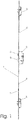
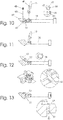
- Fig. 1 shows a locking device 1 with a main lock box 2 and two secondary lock boxes 3, which are identical.
- a drive rod 4 connects the main lock case 2 and the secondary lock boxes 3.
- a latch 5 and a latch bolt 6 are provided at the main lock box 2. Latch 5 and latch bolt 6 occur in the illustrated locking position of the locking device 1 in front of a forend 7, which forms an end face of the main lock box 2 and the secondary lock boxes 3 and which the drive rod 4 provides a cover and guide.
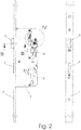
- the locking device 1 is an automatic lock, which consists of the in Fig. 2 standby position shown automatically enters a locked position.
- the drive rod 4 is spring-loaded in its locking direction and will, as will be shown below, held in the ready position fixing.
- a pusher 8 is provided for coupling with a pusher, not shown here.
- the lock can be operated via the handle.
- a cylinder bore 9 also allows the attachment of a lock cylinder for further operation.
- the Fig. 3 illustrates the structure of the latch bolt 6. This occurs in its ready position Fig. 2 and 3 by a measure 10 in front of the forend 7 before.
- the case slope 11 hits the frame or a frame part attached thereto and is pushed back in the direction of the arrow 12 in the lock case 2.
- a blocking element 13 and a spring 14 acting thereon initially prevents a penetration beyond the measure 10 of the latch bolt 6.
- the locking element 13 engages behind a locking edge 15 the edge of the latch window 16 in the faceplate 7.
- the locking element 13 is pivotable in the latch bolt. 6 stored, as already from the EP 0431369 A2 is known.
- a latch spring 19 is supported and causes a predisposition of the latch bolt 6.
- a collar 21 is formed.
- the locking device 22 is pivotally mounted about an axis 27 and protrudes with a second arm 28 approximately diametrically to the axis 27 in the displacement region of a drive rod slider 29.
- a leg spring 30 causes based on the Fig. 4 one Torque counterclockwise, so that the edge 26 is pressed against the collar 21.
- the free end 31 of the second arm 28 forms a locking edge 32, which the driving rod slider 29 at a projection 33 (FIG. Fig. 7 ) assigned.
- the standing under spring pressure in its locking direction 34 espagnolette 29 is thereby held in its open position.
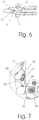
- the latch bolt 6 now clearly ahead of the forend 7 with the case slope 11. Also, the latch 5 is preconnected. This is due to the in Fig. 6 If the wing when closing to the frame or a frame part assigned to this, the latch bolt is initially pushed closed lockbox inward and occurs at almost complete surface-parallel position of the wing to the frame due to the latch spring in a latch bolt opening of a frame-side provided strike plate. In this case, the blocking element 13 comes to rest on the edge of the latch bolt opening and pivots in the direction of the trailing edge 11. The locking edge 15 is displaced into the region of the trap window 16 and the latch bolt is above the dimension 10 (FIG. Fig. 3 ) pushed out of the lock case 2.
- the blocking element 13 forms a button-like trigger 36, which protrudes beyond a trailing edge 37.
- the case edge 37 extends inclined to the shaft 38.
- the case slope 11 opposite recess 39 the locking element 13 is projecting with the trigger 36 in the latch bolt 6 pivotally mounted.
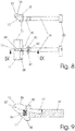
- the FIGS. 8 and 9 protrudes the locking element 13 forming blocking edge 15 in front of the shaft 38.
- the blocking element 13 forms two lateral bearing journals 40, 41 for mounting in the latch bolt 6. Through this, the otherwise flat rectangular locking element 13 receives a T-shaped contour. From the Fig. 8 It can be seen that the bearing journals 40, 41 are received in a bearing recess 42.
- the bearing recess 42 is assigned to the trap shoulder 35.
- the cropping magnification of the Figure 10 makes it clear that the bearing journals 40, 41 have a cylindrical cross-section with two surface-parallel flattened portions 43, 44.
- the bearing recess 42 arranged in the latch shoulder 35 of the latch bolt 6 is aligned transversely to the direction of movement of the latch bolt and has an open-edged omega-shaped form. This has a narrow opening 46 located near the opening edge 46.
- the constriction 46 is dimensioned such that the spacing of the plane-parallel flattenings 43, 44 is dimensioned somewhat smaller than the clear dimension at the constriction 46.
- a recess 47 is attached, which is assigned a correspondingly sized coil spring 48. This is assigned to the blocking element 13 on a pin 49.
- the coil spring 48 and the blocking element 13 are brought to the case head 17 and the trap shoulder 35, respectively. Both can be moved parallel to each other.
- the flats 43, 44 running parallel to the direction 50 permit insertion into the bearing recess 42 without tools (FIG. Fig. 11 ).
- a pivoting movement causes the bearing journals 40, 41 now with their greater longitudinal extension (along the flattenings 43, 44) engage behind the constriction and thus engage behind the constriction 46.
- the Fig. 13 is in the trailing shoulder 35 facing away from the constriction 46 recess 51 is provided.
- lateral knockouts 52 are mounted, whose distance from the bearing recess 42 is dimensioned according to the distance of the bearing recess 42 to the recess 51, so that the knockouts 52 pass in a further pivoting movement in the recess 51 which extend on both sides of the recess 39 , In a further pivoting movement, the knockouts 52 lock behind webs 53, so that the blocking element 13 is fixed against the restoring force of the spiral spring 48.
Description
Die Erfindung betrifft eine Verriegelungseinrichtung nach dem Oberbegriff des Anspruchs 1.The invention relates to a locking device according to the preamble of claim 1.
Mit der
Mit der
Aus der
Aufgabe der Erfindung ist es daher, eine Verriegelungseinrichtung bereitzustellen, die einerseits eine sichere Verriegelung über einen Fallenriegel erlaubt, andererseits aber einfacher aufbaut und kostengünstiger ist.The object of the invention is therefore to provide a locking device, on the one hand allows a secure locking on a latch bolt, but on the other hand, simpler and more cost-effective.
Zur Lösung dieser Aufgabe sieht die Erfindung die Merkmale des Anspruchs 1 vor.To solve this problem, the invention provides the features of claim 1.
Bedingt durch die Ausgestaltung lässt sich die Falle als vormontierbare Bauteilgruppe definieren und auf einfache Art und Weise herstellen. Sperrelement und Auslöser sind in einem Bauteil vereinigt und sind sicher und funktionsgerecht an dem Fallenriegel gelagert.Due to the design, the trap can be defined as a pre-assembled component group and produced in a simple manner. Locking element and release are combined in one component and are safe and functionally mounted on the latch bolt.
Bei einer Ausgestaltung, die vorsieht, dass der Auslöser im Wesentlichen einen flachrechteckigen Querschnitt besitzt, von dem die Lagerzapfen und axial dazu gerichtete Vorprägung vorstehen, kann erreicht werden, dass das Sperrelement sehr sicher an der Falle befestigt ist.In an embodiment which provides that the trigger has substantially a flat rectangular cross section, from which protrude the bearing pin and axially directed Vorprägung, it can be achieved that the blocking element is very securely attached to the case.
Wenn dem Fallenkopf eine dazu verjüngt ausgeführte Fallenschulter zugeordnet ist, in der die Lagerung der Lagerzapfen erfolgt, dann führt dies zu einer Anordnung der Lagerung, die zum einen gesichert und schwer manipulierbar ist.If the case head is associated with a tapered running trap shoulder, in which the bearing of the bearing pin is done, then this leads to an arrangement of storage, which is on the one hand secured and difficult to manipulate.
Bei einer Verriegelungseinrichtung mit einem Hauptschlosskasten, wenigstens einem Neben- oder Zusatzschlosskasten und wenigstens einer den Neben- oder Zusatzschlosskasten mit dem Hauptschließkasten verbindenden Treibstange, wobei der Neben- oder Zusatzschlosskasten einen in Entriegelungsstellung frei zurückschließbaren Riegel aufweist, und zumindest ein Fallenriegel durch eine Fallenfeder über die Fallenstellung hinaus in eine Verriegelungsstellung schiebbar ist, kann vorgesehen werden, dass der Fallenriegel eine Sperrvorrichtung für die Treibstange bildet, die Feder- oder Schwerkraft belastet in eine Verriegelungsstellung gedrängt wird.In a locking device with a main lock box, at least one secondary or additional lock case and at least one auxiliary or additional lock box with the main lock box connecting drive rod, the secondary or additional lock case has a freely zurückschließbaren in unlocking latch, and at least one latch bolt by a latch spring on the Fallenstellung is pushed out into a locking position, it can be provided that the latch bolt a locking device for the Driving rod forms the spring or gravity loaded in a locking position is urged.
Bedingt dadurch wird eine automatisch verriegelnde Verriegelungseinrichtung erreicht, die mit einem Minimum an Bauteilen geschaffen werden kann. Dabei ist die Art der Verriegelung in den Zusatzschließkästen nicht von Bedeutung. Die entfernt vom Hauptschlosskasten liegenden Verriegelungen der Zusatzschließkästen werden erst ausgelöst, wenn der Fallenriegel des Hauptschlosskastens bis zur Fallenentlage vorschließt, wobei der Hauptschlosskasten durch die Nähe des Bediengriffs sicher an den Rahmen gepresst wird.As a result, an automatically locking locking device is achieved, which can be created with a minimum of components. The type of locking in the additional lock boxes is not important. The lying away from the main lock box locks the additional lock boxes are only triggered when the latch bolt of the main lock box vorschließ to the case insert, the main lock case is pressed by the proximity of the control handle securely to the frame.
Eine Weiterbildung sieht vor, dass die Sperrvorrichtung dem Fallenschwanz zugeordnet ist und mit einem Treibstangenschieber zusammenwirkt. Damit wird der erforderliche Bauraum in einen Bereich des Hautschlosskastens verlagert, der ansonsten frei von beweglichen Bauteilen bleibt.A further embodiment provides that the locking device is associated with the latch tail and cooperates with a drive rod slider. Thus, the required space is moved to an area of the skin lock box, which otherwise remains free of moving components.
Eine einfache Ausgestaltung, die sich mit wenigen Bauteilen realisieren lässt, wird erreicht, indem die Sperrvorrichtung aus einem schwenkbar im Hauptschließkasten gelagerten zweiarmigen Hebel besteht, der mit einem ersten Arm am Fallenschwanz angreift und mit seinem zweiten Arm dem Treibstangenschieber zugeordnet ist.A simple design, which can be realized with few components, is achieved by the locking device consists of a pivotally mounted in the main lock box two-armed lever which engages with a first arm on the tail tail and is associated with the second arm of the espagnolette.
Eine Mehrfachnutzung der Bauteilgeometrien kann erreicht werden, wenn der Hebel am Fallenschwanz dem Fallenumsteller zugeordnet ist.Multiple use of the component geometries can be achieved if the lever on the tail tail is assigned to the trap diverter.
Weitere vorteilhafte Ausgestaltungen ergeben sich aus den Zeichnungen. Es zeigt:
- Fig. 1
- eine Verriegelungseinrichtung in einer Übersichtsdarstellung,
- Fig. 2
- eine vergrößerte Darstellung eines Hauptschosskastens in einer Seit- und einer Frontansicht in Bereitschaftsstellung,
- Fig. 3
- einen Schnitt entlang der Linie III -III in
Fig. 2 , - Fig. 4
- eine Detailvergrößerung des Ausschnitts IV in
Fig. 2 - Fig. 5
- eine vergrößerte Darstellung eines Hauptschosskastens in einer Seit- und einer Frontansicht in Verriegelungsstellung,
- Fig. 6
- einen Schnitt entlang der Linie VI - VI in
Fig. 5 , - Fig. 7
- eine Detailvergrößerung des Ausschnitts VII in
Fig. 5 , - Fig. 8
- eine Falle der Verriegelungsvorrichtung als Einzelbauteil in Drauf- und Seitenansicht,
- Fig. 9
- einen Schnitt entlang der Linie IX-IX in
Fig. 8 , - Fig. 10
- einen ersten Montageschritt der Fallenriegelbaugruppe,
- Fig. 11
- eine alternative Fallenausgestaltung in Montagestellung,
- Fig. 12
- den Fallenriegel nach
Fig. 11 mit einem teilweise verschwenkten Sperrelement und Ausschnittsvergrößerungen und eine räumlichen Darstellung, und - Fig. 13
- Draufsicht und Detailausschnitt eines Fallenriegels nach
Fig. 10 .
- Fig. 1
- a locking device in an overview,
- Fig. 2
- an enlarged view of a main floor box in a side and a front view in the ready position,
- Fig. 3
- a section along the line III -III in
Fig. 2 . - Fig. 4
- a detail enlargement of the section IV in
Fig. 2 - Fig. 5
- an enlarged view of a main box in a side and a front view in the locked position,
- Fig. 6
- a section along the line VI - VI in
Fig. 5 . - Fig. 7
- an enlarged detail of section VII in
Fig. 5 . - Fig. 8
- a case of the locking device as a single component in plan and side view,
- Fig. 9
- a section along the line IX-IX in
Fig. 8 . - Fig. 10
- a first assembly step of the latch bolt assembly,
- Fig. 11
- an alternative trap design in assembly position,
- Fig. 12
- the latch bolt after
Fig. 11 with a partially pivoted blocking element and detail enlargements and a spatial representation, and - Fig. 13
- Top view and detail of a latch bolt behind
Fig. 10 ,
Bei der Verriegelungsvorrichtung 1 handelt es sich um ein Automatik-Schloss, welches aus der in
Die
Ein sich an den Fallenkopf 17 anschließender Fallenschwanz 18 reicht ausweislich der
In der
Infolge dieser Verlagerung des Fallenriegels 6 drängt auch der Fallenumsteller 20 vor. Dies führt zu einem Verschwenken der Sperrvorrichtung 22 um die Achse 27 in der
In der Baugruppendarstellung des Fallenriegels 6 nach
Das Sperrelement 13 bildet einen tasterähnlichen Auslöser 36 aus, der über eine Fallenkante 37 vorsteht. Die Fallenkante 37 verläuft dabei geneigt zum Schaft 38. In einer seitlichen, der Fallenschräge 11 gegenüberliegenden Ausnehmung 39 liegt das Sperrelement 13 mit dem Auslöser 36 vorragend im Fallenriegel 6 schwenkbeweglich gelagert. Ausweislich der
Die Ausschnitts-Vergrößerung der
In der Ausnehmung 39 ist eine Ausnehmung 47 angebracht, der eine entsprechend dimensionierte Spiralfeder 48 zugeordnet wird. Diese ist dem Sperrelement 13 an einem Zapfen 49 zugeordnet.In the
Zur Montage der Fallenriegel-Baugruppe ermöglicht sich dadurch die in den
- 11
- Verriegelungseinrichtunglocking device
- 22
- HauptschlosskastenMain lock case
- 33
- NebenschlosskastenIn addition to the lock case
- 44
- Treibstangedriving rod
- 55
- Riegelbars
- 66
- Fallenriegellatchbolts
- 77
- Stulpstulp
- 88th
- Druckernussprinter nut
- 99
- Zylinderbohrungbore
- 1010
- Maßmeasure
- 1111
- Fallenschrägecatch slope
- 1212
- Pfeilarrow
- 1313
- Sperrelementblocking element
- 1414
- Federfeather
- 1515
- Sperrkanteblocking edge
- 1616
- Fallenfenstercase window
- 1717
- Fallenkopfdrophead
- 1818
- Fallenschwanzcatch tail
- 1919
- Fallenfedercase spring
- 2020
- FallenumstellerFallenumsteller
- 2121
- BundFederation
- 2222
- Sperrvorrichtunglocking device
- 2424
- erster Armfirst arm
- 2525
- Kraftrichtungdirection of force
- 2626
- Kanteedge
- 2727
- Achseaxis
- 2828
- zweiter Armsecond arm
- 2929
- TreibstangenschieberDriving rod slide
- 3030
- SchenkelfederLeg spring
- 3131
- EndeThe End
- 3232
- Sperrkanteblocking edge
- 3333
- Vorsprunghead Start
- 3434
- Verriegelungsrichtunglocking direction
- 3535
- Fallenschultercase shoulder
- 3636
- Auslösertrigger
- 3737
- Fallenkanteweir
- 3838
- Schaftshaft
- 3939
- Ausnehmungrecess
- 4040
- Lagerzapfenpivot
- 4141
- Lagerzapfenpivot
- 4242
- Lagerausnehmungbearing recess
- 4343
- Abflachungflattening
- 4444
- Abflachungflattening
- 4545
- Öffnungsrandopening edge
- 4646
- Engstellebottleneck
- 4747
- Ausnehmungrecess
- 4848
- Spiralfederspiral spring
- 4949
- Zapfenspigot
- 5050
- Richtungdirection
- 5151
- Ausnehmungrecess
- 5252
- Vorprägungprestamping
- 5353
- Stegweb
Claims (7)
- Locking device (1) with a latch bolt (6), which is under the effect of a latch spring (19) and which, with the door leaf open, is to be locked by a blocking element (13) in an only partially extended intermediate position, with its latch bevels (11) arranged on the face side projecting over a face late (7), wherein the blocking element (13) is to be moved out of position by the impingement on the strike plate side of an actuator (36), arranged projecting on the face plate side in the region of the blocking surface of the latch bolt (6), and thereby allows the latch bolt (6) to pass into its fully extended position, wherein the actuator (36) is mounted such as to pivot in the latch bolt (6), and is provided with a blocking edge (15), forming at the same time the blocking element (13), and wherein the blocking element (13) forms two lateral bearing journals (40, 41) for the bearing in the latch bolt (6), characterized in that the bearing journals (40, 41) have a cylindrical cross-section with two surface-parallel flat regions (43, 44), and the latch bolt (6) has an omega-shaped bearing cut-out (42), open transverse to its movement direction, with a narrow point (46) located close to the opening edge (45).
- Locking device (1) according to claim 1, characterized in that the actuator (36) has an essentially flat rectangular cross-section, from which the bearing journals (40, 41) project, as well as a projection (52) oriented axially thereto.
- Locking device (1) according to claim 1 or 2, characterized in that a latch shoulder (35) is allocated to the latch head (17), configured such as to taper towards it, in which the bearing journals (40, 41) are mounted.
- Locking device (1) according to claim 1, with a main lock case (2), at least one ancillary or additional lock case (3), and at least one drive rod (4) connecting the ancillary or additional lock case (3) to the main lock case (2), wherein the ancillary or additional lock case (3) comprises a latch (5) which can be reset into an unlocking position, and at least one latch bolt (6) can be displaced by a latch spring (19) over the latch position out into a locking position, characterized in that the latch bolt (6) forms a blocking device (22) for the drive rod (4), which, subject to spring force or the force of gravity, is forced into a locking position.
- Locking device (1) according to claim 4, characterized in that the blocking device (22) is allocated to the latch tail (18) and interacts with a drive rod sliding element (29).
- Locking device (1) according to claim 4 or 5, characterized in that the blocking device (22) consists of a two-armed lever (24, 28) mounted such as to pivot in the main lock case (2), which engages with a first arm (24) at the latch tail (18) and is allocated with its second arm (28) to the drive rod sliding element (29).
- Locking device (1) according to any one of claims 4 to 6, characterized in that the two-armed lever (24, 28) at the latch tail (18) is allocated to the latch reversing element (20).
Applications Claiming Priority (1)
| Application Number | Priority Date | Filing Date | Title |
|---|---|---|---|
| DE202013009210U DE202013009210U1 (en) | 2013-10-18 | 2013-10-18 | locking device |
Publications (3)
| Publication Number | Publication Date |
|---|---|
| EP2862991A2 EP2862991A2 (en) | 2015-04-22 |
| EP2862991A3 EP2862991A3 (en) | 2016-03-23 |
| EP2862991B1 true EP2862991B1 (en) | 2017-03-29 |
Family
ID=49713991
Family Applications (1)
| Application Number | Title | Priority Date | Filing Date |
|---|---|---|---|
| EP14184694.9A Not-in-force EP2862991B1 (en) | 2013-10-18 | 2014-09-15 | Locking device |
Country Status (3)
| Country | Link |
|---|---|
| EP (1) | EP2862991B1 (en) |
| DE (1) | DE202013009210U1 (en) |
| PL (1) | PL2862991T3 (en) |
Families Citing this family (8)
| Publication number | Priority date | Publication date | Assignee | Title |
|---|---|---|---|---|
| DE102014102041A1 (en) * | 2014-02-18 | 2015-08-20 | Assa Abloy Sicherheitstechnik Gmbh | Closing edge flap |
| AT515799B1 (en) * | 2014-03-31 | 2015-12-15 | Roto Frank Ag | lock |
| CN103993788A (en) * | 2014-06-07 | 2014-08-20 | 李健 | Safety door lock body |
| DE202015000108U1 (en) | 2015-01-14 | 2015-02-05 | Kfv Karl Fliether Gmbh & Co. Kg | Locking device with a latch bolt |
| DE202015000107U1 (en) | 2015-01-14 | 2015-02-05 | Kfv Karl Fliether Gmbh & Co. Kg | lock |
| DE202016001542U1 (en) | 2016-03-10 | 2016-05-09 | Kfv Karl Fliether Gmbh & Co. Kg | locking device |
| GB201707144D0 (en) | 2017-05-04 | 2017-06-21 | Era Home Security Ltd | Locking assembly |
| ES2847586T3 (en) * | 2018-06-07 | 2021-08-03 | Dormakaba Deutschland Gmbh | Mortise lock bolt |
Family Cites Families (6)
| Publication number | Priority date | Publication date | Assignee | Title |
|---|---|---|---|---|
| DE8914367U1 (en) | 1989-12-06 | 1991-04-04 | Bks Gmbh, 5620 Velbert, De | |
| DE29605517U1 (en) | 1996-03-26 | 1997-07-24 | Gretsch Unitas Gmbh | Locking device |
| US6109666A (en) * | 1998-09-23 | 2000-08-29 | Ferco International, Ferrures Et Serrures De Batiment Sa | Espagnolette or espagnolette-lock for a door, French window or the like |
| DE102004025034B4 (en) * | 2004-05-18 | 2012-01-05 | Volkswagen Ag | hinge assembly |
| DE202006010747U1 (en) * | 2006-07-12 | 2007-11-22 | Kfv Karl Fliether Gmbh & Co. Kg | Lock with trap |
| DE202011001842U1 (en) | 2011-01-14 | 2011-04-21 | Bks Gmbh | locking device |
-
2013
- 2013-10-18 DE DE202013009210U patent/DE202013009210U1/en not_active Expired - Lifetime
-
2014
- 2014-09-15 PL PL14184694T patent/PL2862991T3/en unknown
- 2014-09-15 EP EP14184694.9A patent/EP2862991B1/en not_active Not-in-force
Also Published As
| Publication number | Publication date |
|---|---|
| EP2862991A3 (en) | 2016-03-23 |
| PL2862991T3 (en) | 2017-09-29 |
| DE202013009210U1 (en) | 2013-11-06 |
| EP2862991A2 (en) | 2015-04-22 |
Similar Documents
| Publication | Publication Date | Title |
|---|---|---|
| EP2862991B1 (en) | Locking device | |
| EP1908900B1 (en) | Lock with swivel trigger | |
| EP1932989A2 (en) | Locking device for doors, windows or similar, in particular an espagnolette lock with panic function and multi-point locking | |
| EP2327850B1 (en) | Lock with panic function | |
| EP2862996A2 (en) | Locking device | |
| DE102005015248B4 (en) | Grand piano lock with an electric door opener | |
| EP0833997B1 (en) | Closing device with door leaf stopping means | |
| EP3426867B1 (en) | Lock | |
| EP1172506B1 (en) | Safety device against wrong operation of espagnolettes | |
| EP2339096A2 (en) | Connecting rod lock with panic function and multiple locking | |
| EP3208407B1 (en) | Lock with a safety device | |
| EP1031686A2 (en) | Lock with handle actuated and lockable main latch bolt | |
| EP3628801B1 (en) | Lock device for a door and a method for opening a door | |
| EP2963213B1 (en) | Lock | |
| EP3216952B1 (en) | Locking device | |
| EP3112564A1 (en) | Self-locking latch lock | |
| AT513470B1 (en) | Locks | |
| DE102017000346B4 (en) | Lock with trap lock | |
| EP2085543B1 (en) | Lock | |
| EP2947240B1 (en) | Lock | |
| EP1699023A2 (en) | Coin lock | |
| DE3002976C2 (en) | Lock with two locking mechanisms | |
| AT515800B1 (en) | mortise lock | |
| DE2822985A1 (en) | Remote operated automatically locking rotating bolt lock - has eccentric arm and toggle lever system for automatic locking | |
| DE102014116326A1 (en) | Lock for a door or a flap |
Legal Events
| Date | Code | Title | Description |
|---|---|---|---|
| PUAI | Public reference made under article 153(3) epc to a published international application that has entered the european phase |
Free format text: ORIGINAL CODE: 0009012 |
|
| 17P | Request for examination filed |
Effective date: 20140915 |
|
| AK | Designated contracting states |
Kind code of ref document: A2 Designated state(s): AL AT BE BG CH CY CZ DE DK EE ES FI FR GB GR HR HU IE IS IT LI LT LU LV MC MK MT NL NO PL PT RO RS SE SI SK SM TR |
|
| AX | Request for extension of the european patent |
Extension state: BA ME |
|
| PUAL | Search report despatched |
Free format text: ORIGINAL CODE: 0009013 |
|
| AK | Designated contracting states |
Kind code of ref document: A3 Designated state(s): AL AT BE BG CH CY CZ DE DK EE ES FI FR GB GR HR HU IE IS IT LI LT LU LV MC MK MT NL NO PL PT RO RS SE SI SK SM TR |
|
| AX | Request for extension of the european patent |
Extension state: BA ME |
|
| RIC1 | Information provided on ipc code assigned before grant |
Ipc: E05B 55/00 20060101AFI20160216BHEP Ipc: E05B 63/20 20060101ALI20160216BHEP Ipc: E05C 9/00 20060101ALI20160216BHEP Ipc: E05B 15/10 20060101ALI20160216BHEP |
|
| R17P | Request for examination filed (corrected) |
Effective date: 20160408 |
|
| GRAP | Despatch of communication of intention to grant a patent |
Free format text: ORIGINAL CODE: EPIDOSNIGR1 |
|
| INTG | Intention to grant announced |
Effective date: 20161208 |
|
| GRAS | Grant fee paid |
Free format text: ORIGINAL CODE: EPIDOSNIGR3 |
|
| GRAA | (expected) grant |
Free format text: ORIGINAL CODE: 0009210 |
|
| AK | Designated contracting states |
Kind code of ref document: B1 Designated state(s): AL AT BE BG CH CY CZ DE DK EE ES FI FR GB GR HR HU IE IS IT LI LT LU LV MC MK MT NL NO PL PT RO RS SE SI SK SM TR |
|
| REG | Reference to a national code |
Ref country code: GB Ref legal event code: FG4D Free format text: NOT ENGLISH |
|
| REG | Reference to a national code |
Ref country code: CH Ref legal event code: EP |
|
| REG | Reference to a national code |
Ref country code: AT Ref legal event code: REF Ref document number: 879924 Country of ref document: AT Kind code of ref document: T Effective date: 20170415 |
|
| REG | Reference to a national code |
Ref country code: IE Ref legal event code: FG4D Free format text: LANGUAGE OF EP DOCUMENT: GERMAN |
|
| REG | Reference to a national code |
Ref country code: DE Ref legal event code: R096 Ref document number: 502014003189 Country of ref document: DE |
|
| REG | Reference to a national code |
Ref country code: NL Ref legal event code: FP |
|
| PG25 | Lapsed in a contracting state [announced via postgrant information from national office to epo] |
Ref country code: NO Free format text: LAPSE BECAUSE OF FAILURE TO SUBMIT A TRANSLATION OF THE DESCRIPTION OR TO PAY THE FEE WITHIN THE PRESCRIBED TIME-LIMIT Effective date: 20170629 Ref country code: GR Free format text: LAPSE BECAUSE OF FAILURE TO SUBMIT A TRANSLATION OF THE DESCRIPTION OR TO PAY THE FEE WITHIN THE PRESCRIBED TIME-LIMIT Effective date: 20170630 Ref country code: LT Free format text: LAPSE BECAUSE OF FAILURE TO SUBMIT A TRANSLATION OF THE DESCRIPTION OR TO PAY THE FEE WITHIN THE PRESCRIBED TIME-LIMIT Effective date: 20170329 Ref country code: HR Free format text: LAPSE BECAUSE OF FAILURE TO SUBMIT A TRANSLATION OF THE DESCRIPTION OR TO PAY THE FEE WITHIN THE PRESCRIBED TIME-LIMIT Effective date: 20170329 Ref country code: FI Free format text: LAPSE BECAUSE OF FAILURE TO SUBMIT A TRANSLATION OF THE DESCRIPTION OR TO PAY THE FEE WITHIN THE PRESCRIBED TIME-LIMIT Effective date: 20170329 |
|
| PG25 | Lapsed in a contracting state [announced via postgrant information from national office to epo] |
Ref country code: RS Free format text: LAPSE BECAUSE OF FAILURE TO SUBMIT A TRANSLATION OF THE DESCRIPTION OR TO PAY THE FEE WITHIN THE PRESCRIBED TIME-LIMIT Effective date: 20170329 Ref country code: LV Free format text: LAPSE BECAUSE OF FAILURE TO SUBMIT A TRANSLATION OF THE DESCRIPTION OR TO PAY THE FEE WITHIN THE PRESCRIBED TIME-LIMIT Effective date: 20170329 Ref country code: BG Free format text: LAPSE BECAUSE OF FAILURE TO SUBMIT A TRANSLATION OF THE DESCRIPTION OR TO PAY THE FEE WITHIN THE PRESCRIBED TIME-LIMIT Effective date: 20170629 Ref country code: SE Free format text: LAPSE BECAUSE OF FAILURE TO SUBMIT A TRANSLATION OF THE DESCRIPTION OR TO PAY THE FEE WITHIN THE PRESCRIBED TIME-LIMIT Effective date: 20170329 |
|
| REG | Reference to a national code |
Ref country code: FR Ref legal event code: PLFP Year of fee payment: 4 |
|
| PG25 | Lapsed in a contracting state [announced via postgrant information from national office to epo] |
Ref country code: RO Free format text: LAPSE BECAUSE OF FAILURE TO SUBMIT A TRANSLATION OF THE DESCRIPTION OR TO PAY THE FEE WITHIN THE PRESCRIBED TIME-LIMIT Effective date: 20170329 Ref country code: CZ Free format text: LAPSE BECAUSE OF FAILURE TO SUBMIT A TRANSLATION OF THE DESCRIPTION OR TO PAY THE FEE WITHIN THE PRESCRIBED TIME-LIMIT Effective date: 20170329 Ref country code: ES Free format text: LAPSE BECAUSE OF FAILURE TO SUBMIT A TRANSLATION OF THE DESCRIPTION OR TO PAY THE FEE WITHIN THE PRESCRIBED TIME-LIMIT Effective date: 20170329 Ref country code: SK Free format text: LAPSE BECAUSE OF FAILURE TO SUBMIT A TRANSLATION OF THE DESCRIPTION OR TO PAY THE FEE WITHIN THE PRESCRIBED TIME-LIMIT Effective date: 20170329 Ref country code: EE Free format text: LAPSE BECAUSE OF FAILURE TO SUBMIT A TRANSLATION OF THE DESCRIPTION OR TO PAY THE FEE WITHIN THE PRESCRIBED TIME-LIMIT Effective date: 20170329 |
|
| PG25 | Lapsed in a contracting state [announced via postgrant information from national office to epo] |
Ref country code: PT Free format text: LAPSE BECAUSE OF FAILURE TO SUBMIT A TRANSLATION OF THE DESCRIPTION OR TO PAY THE FEE WITHIN THE PRESCRIBED TIME-LIMIT Effective date: 20170731 Ref country code: IS Free format text: LAPSE BECAUSE OF FAILURE TO SUBMIT A TRANSLATION OF THE DESCRIPTION OR TO PAY THE FEE WITHIN THE PRESCRIBED TIME-LIMIT Effective date: 20170729 Ref country code: SM Free format text: LAPSE BECAUSE OF FAILURE TO SUBMIT A TRANSLATION OF THE DESCRIPTION OR TO PAY THE FEE WITHIN THE PRESCRIBED TIME-LIMIT Effective date: 20170329 |
|
| REG | Reference to a national code |
Ref country code: DE Ref legal event code: R097 Ref document number: 502014003189 Country of ref document: DE |
|
| PG25 | Lapsed in a contracting state [announced via postgrant information from national office to epo] |
Ref country code: DK Free format text: LAPSE BECAUSE OF FAILURE TO SUBMIT A TRANSLATION OF THE DESCRIPTION OR TO PAY THE FEE WITHIN THE PRESCRIBED TIME-LIMIT Effective date: 20170329 |
|
| PLBE | No opposition filed within time limit |
Free format text: ORIGINAL CODE: 0009261 |
|
| STAA | Information on the status of an ep patent application or granted ep patent |
Free format text: STATUS: NO OPPOSITION FILED WITHIN TIME LIMIT |
|
| 26N | No opposition filed |
Effective date: 20180103 |
|
| PG25 | Lapsed in a contracting state [announced via postgrant information from national office to epo] |
Ref country code: MC Free format text: LAPSE BECAUSE OF FAILURE TO SUBMIT A TRANSLATION OF THE DESCRIPTION OR TO PAY THE FEE WITHIN THE PRESCRIBED TIME-LIMIT Effective date: 20170329 Ref country code: SI Free format text: LAPSE BECAUSE OF FAILURE TO SUBMIT A TRANSLATION OF THE DESCRIPTION OR TO PAY THE FEE WITHIN THE PRESCRIBED TIME-LIMIT Effective date: 20170329 |
|
| REG | Reference to a national code |
Ref country code: IE Ref legal event code: MM4A |
|
| PG25 | Lapsed in a contracting state [announced via postgrant information from national office to epo] |
Ref country code: LU Free format text: LAPSE BECAUSE OF NON-PAYMENT OF DUE FEES Effective date: 20170915 |
|
| PG25 | Lapsed in a contracting state [announced via postgrant information from national office to epo] |
Ref country code: IE Free format text: LAPSE BECAUSE OF NON-PAYMENT OF DUE FEES Effective date: 20170915 |
|
| REG | Reference to a national code |
Ref country code: FR Ref legal event code: PLFP Year of fee payment: 5 |
|
| PG25 | Lapsed in a contracting state [announced via postgrant information from national office to epo] |
Ref country code: MT Free format text: LAPSE BECAUSE OF FAILURE TO SUBMIT A TRANSLATION OF THE DESCRIPTION OR TO PAY THE FEE WITHIN THE PRESCRIBED TIME-LIMIT Effective date: 20170329 |
|
| PG25 | Lapsed in a contracting state [announced via postgrant information from national office to epo] |
Ref country code: HU Free format text: LAPSE BECAUSE OF FAILURE TO SUBMIT A TRANSLATION OF THE DESCRIPTION OR TO PAY THE FEE WITHIN THE PRESCRIBED TIME-LIMIT; INVALID AB INITIO Effective date: 20140915 |
|
| PG25 | Lapsed in a contracting state [announced via postgrant information from national office to epo] |
Ref country code: CY Free format text: LAPSE BECAUSE OF FAILURE TO SUBMIT A TRANSLATION OF THE DESCRIPTION OR TO PAY THE FEE WITHIN THE PRESCRIBED TIME-LIMIT Effective date: 20170329 |
|
| PG25 | Lapsed in a contracting state [announced via postgrant information from national office to epo] |
Ref country code: MK Free format text: LAPSE BECAUSE OF FAILURE TO SUBMIT A TRANSLATION OF THE DESCRIPTION OR TO PAY THE FEE WITHIN THE PRESCRIBED TIME-LIMIT Effective date: 20170329 |
|
| PG25 | Lapsed in a contracting state [announced via postgrant information from national office to epo] |
Ref country code: TR Free format text: LAPSE BECAUSE OF FAILURE TO SUBMIT A TRANSLATION OF THE DESCRIPTION OR TO PAY THE FEE WITHIN THE PRESCRIBED TIME-LIMIT Effective date: 20170329 |
|
| PG25 | Lapsed in a contracting state [announced via postgrant information from national office to epo] |
Ref country code: AL Free format text: LAPSE BECAUSE OF FAILURE TO SUBMIT A TRANSLATION OF THE DESCRIPTION OR TO PAY THE FEE WITHIN THE PRESCRIBED TIME-LIMIT Effective date: 20170329 |
|
| PGFP | Annual fee paid to national office [announced via postgrant information from national office to epo] |
Ref country code: GB Payment date: 20200924 Year of fee payment: 7 Ref country code: NL Payment date: 20200924 Year of fee payment: 7 Ref country code: FR Payment date: 20200925 Year of fee payment: 7 |
|
| PGFP | Annual fee paid to national office [announced via postgrant information from national office to epo] |
Ref country code: BE Payment date: 20200924 Year of fee payment: 7 Ref country code: AT Payment date: 20200922 Year of fee payment: 7 Ref country code: CH Payment date: 20200925 Year of fee payment: 7 Ref country code: PL Payment date: 20200826 Year of fee payment: 7 |
|
| PGFP | Annual fee paid to national office [announced via postgrant information from national office to epo] |
Ref country code: IT Payment date: 20200930 Year of fee payment: 7 |
|
| PGFP | Annual fee paid to national office [announced via postgrant information from national office to epo] |
Ref country code: DE Payment date: 20210923 Year of fee payment: 8 |
|
| REG | Reference to a national code |
Ref country code: CH Ref legal event code: PL |
|
| REG | Reference to a national code |
Ref country code: NL Ref legal event code: MM Effective date: 20211001 |
|
| REG | Reference to a national code |
Ref country code: AT Ref legal event code: MM01 Ref document number: 879924 Country of ref document: AT Kind code of ref document: T Effective date: 20210915 |
|
| REG | Reference to a national code |
Ref country code: BE Ref legal event code: MM Effective date: 20210930 |
|
| GBPC | Gb: european patent ceased through non-payment of renewal fee |
Effective date: 20210915 |
|
| PG25 | Lapsed in a contracting state [announced via postgrant information from national office to epo] |
Ref country code: NL Free format text: LAPSE BECAUSE OF NON-PAYMENT OF DUE FEES Effective date: 20211001 |
|
| PG25 | Lapsed in a contracting state [announced via postgrant information from national office to epo] |
Ref country code: GB Free format text: LAPSE BECAUSE OF NON-PAYMENT OF DUE FEES Effective date: 20210915 Ref country code: FR Free format text: LAPSE BECAUSE OF NON-PAYMENT OF DUE FEES Effective date: 20210930 Ref country code: BE Free format text: LAPSE BECAUSE OF NON-PAYMENT OF DUE FEES Effective date: 20210930 |
|
| PG25 | Lapsed in a contracting state [announced via postgrant information from national office to epo] |
Ref country code: LI Free format text: LAPSE BECAUSE OF NON-PAYMENT OF DUE FEES Effective date: 20210930 Ref country code: CH Free format text: LAPSE BECAUSE OF NON-PAYMENT OF DUE FEES Effective date: 20210930 Ref country code: AT Free format text: LAPSE BECAUSE OF NON-PAYMENT OF DUE FEES Effective date: 20210915 |
|
| PG25 | Lapsed in a contracting state [announced via postgrant information from national office to epo] |
Ref country code: IT Free format text: LAPSE BECAUSE OF NON-PAYMENT OF DUE FEES Effective date: 20210915 |
|
| REG | Reference to a national code |
Ref country code: DE Ref legal event code: R119 Ref document number: 502014003189 Country of ref document: DE |
|
| PG25 | Lapsed in a contracting state [announced via postgrant information from national office to epo] |
Ref country code: PL Free format text: LAPSE BECAUSE OF NON-PAYMENT OF DUE FEES Effective date: 20210915 |
|
| PG25 | Lapsed in a contracting state [announced via postgrant information from national office to epo] |
Ref country code: DE Free format text: LAPSE BECAUSE OF NON-PAYMENT OF DUE FEES Effective date: 20230401 |