EP2925932B1 - Bridging device for expansion joints - Google Patents
Bridging device for expansion joints Download PDFInfo
- Publication number
- EP2925932B1 EP2925932B1 EP13799208.7A EP13799208A EP2925932B1 EP 2925932 B1 EP2925932 B1 EP 2925932B1 EP 13799208 A EP13799208 A EP 13799208A EP 2925932 B1 EP2925932 B1 EP 2925932B1
- Authority
- EP
- European Patent Office
- Prior art keywords
- expansion
- support profiles
- cross
- bridging device
- members
- Prior art date
- Legal status (The legal status is an assumption and is not a legal conclusion. Google has not performed a legal analysis and makes no representation as to the accuracy of the status listed.)
- Active
Links
- 241000446313 Lamella Species 0.000 claims description 8
- 238000007789 sealing Methods 0.000 claims description 8
- 238000006073 displacement reaction Methods 0.000 claims description 7
- 125000006850 spacer group Chemical group 0.000 claims description 6
- 239000000945 filler Substances 0.000 claims 13
- 230000006378 damage Effects 0.000 description 6
- 230000007704 transition Effects 0.000 description 6
- 238000010276 construction Methods 0.000 description 5
- 230000008901 benefit Effects 0.000 description 4
- 230000008859 change Effects 0.000 description 4
- 239000000463 material Substances 0.000 description 4
- 238000003860 storage Methods 0.000 description 4
- 230000008439 repair process Effects 0.000 description 3
- 230000008602 contraction Effects 0.000 description 2
- 238000009826 distribution Methods 0.000 description 2
- 238000004321 preservation Methods 0.000 description 2
- 230000000284 resting effect Effects 0.000 description 2
- 238000000926 separation method Methods 0.000 description 2
- 230000001960 triggered effect Effects 0.000 description 2
- 230000006978 adaptation Effects 0.000 description 1
- 150000001875 compounds Chemical class 0.000 description 1
- 230000003750 conditioning effect Effects 0.000 description 1
- 230000007423 decrease Effects 0.000 description 1
- 230000000694 effects Effects 0.000 description 1
- 238000012432 intermediate storage Methods 0.000 description 1
- 230000002045 lasting effect Effects 0.000 description 1
- 239000007788 liquid Substances 0.000 description 1
- 238000004519 manufacturing process Methods 0.000 description 1
- 230000035515 penetration Effects 0.000 description 1
- 230000009467 reduction Effects 0.000 description 1
- 238000005096 rolling process Methods 0.000 description 1
- 230000035939 shock Effects 0.000 description 1
- 230000003068 static effect Effects 0.000 description 1
- 239000003351 stiffener Substances 0.000 description 1
Images


Classifications
-
- E—FIXED CONSTRUCTIONS
- E01—CONSTRUCTION OF ROADS, RAILWAYS, OR BRIDGES
- E01D—CONSTRUCTION OF BRIDGES, ELEVATED ROADWAYS OR VIADUCTS; ASSEMBLY OF BRIDGES
- E01D19/00—Structural or constructional details of bridges
- E01D19/06—Arrangement, construction or bridging of expansion joints
- E01D19/062—Joints having intermediate beams
-
- E—FIXED CONSTRUCTIONS
- E01—CONSTRUCTION OF ROADS, RAILWAYS, OR BRIDGES
- E01C—CONSTRUCTION OF, OR SURFACES FOR, ROADS, SPORTS GROUNDS, OR THE LIKE; MACHINES OR AUXILIARY TOOLS FOR CONSTRUCTION OR REPAIR
- E01C11/00—Details of pavings
-
- E—FIXED CONSTRUCTIONS
- E01—CONSTRUCTION OF ROADS, RAILWAYS, OR BRIDGES
- E01C—CONSTRUCTION OF, OR SURFACES FOR, ROADS, SPORTS GROUNDS, OR THE LIKE; MACHINES OR AUXILIARY TOOLS FOR CONSTRUCTION OR REPAIR
- E01C11/00—Details of pavings
- E01C11/02—Arrangement or construction of joints; Methods of making joints; Packing for joints
-
- E—FIXED CONSTRUCTIONS
- E01—CONSTRUCTION OF ROADS, RAILWAYS, OR BRIDGES
- E01C—CONSTRUCTION OF, OR SURFACES FOR, ROADS, SPORTS GROUNDS, OR THE LIKE; MACHINES OR AUXILIARY TOOLS FOR CONSTRUCTION OR REPAIR
- E01C11/00—Details of pavings
- E01C11/16—Reinforcements
Definitions
- the invention relates to an expansion joint bridging device in the form of a lamellar roadway transition, which bridges an existing between two structural parts of a navigable structure expansion joint, which is spanned by at least two trusses.
- the latter are based on both structural parts load-bearing, at least one of the load-bearing supports a sliding movement of the respective traverse relative to the relevant part of the building permits.
- At least one lamella arranged above the trusses is displaceably supported on the trusses relative to the trusses, with a plurality of lamellae being oriented at least substantially parallel to one another and also being displaceable relative to one another.
- expansion joints are provided between the abutment and superstructure and / or between sections of the superstructure to allow a damage-free thermal expansion or contraction of the superstructure.
- expansion joints in the range of up to several meters are required.
- expansion joint bridging devices are provided.
- lamellae-lane transitions in which two bridge parts (in this sense also the abutment as a "bridge part") are interconnected by at least two mutually spaced trusses, that the facing ends of respective bridge parts a relative movement in Longitudinal direction of the trusses to each other and away from each other.
- On the trusses are spaced from each other, relatively movable and substantially transverse to the longitudinal direction of the trusses extending lamellae whose respective upper side substantially lie at the height of the roadway of the bridge or may form this, although also embodiments are known in which separate on the lamellae at the top, the drivable surface forming elements are arranged.
- the expansion joint system comprises a plurality of mutually spaced and displaceable lamellae, which are supported on a plurality of ends mounted in boxes trusses.
- the trusses are each movable on one side in the transverse direction to the roadway of the bridge within storage boxes, so that occurring in this direction forces or displacements, eg by an earthquake, lead to corresponding transverse displacements of the trusses.
- the disadvantage is that exceptionally large changes occurring in earthquakes of the gap width of the expansion joint can not be compensated if the lamellae are already together, which can lead to destruction of the expansion joint system or to a detachment of the building parts, causing the bridge after Initially, an earthquake will no longer be passable.
- EP 1355009 B1 a bridging device for joint gaps between bridge parts of the type mentioned above, which if possible even after an earthquake of vehicles - albeit limited and with much more difficult effort - be drivable.
- the expansion joint construction allows proper positional changes of the adjacent to the expansion joint bridge parts to each other within the first limits without further notice.
- An additional safety device arranged on one of the bridge parts and on the expansion joint construction is intended to enable further changes in position of the bridge parts to each other without destroying the function of the bridging device or separating the expansion joint construction from the bridge parts.
- the safety device comprises at least two firmly interconnected elements, which are separated when a defined limit load is exceeded and then mutually movable in a defined manner, wherein one of the two elements can be arranged firmly on one of the two bridge parts.
- additional position changes in the direction of the trusses and / or transverse movements of the bridge parts to each other should be compensated.
- the safety device represents a predetermined breaking point, which requires extensive repair measures after exceeding the defined limit load in the transverse direction to the slats of the expansion joint construction. First, the roadway transition must be restored to its original position. Subsequently, certain elements of the expansion joint construction including the broken safety device must be replaced and repaired to these adjacent connections.
- the object of the invention is therefore to provide an improved, functionally optimized expansion joint bridging device of the type mentioned above, which also optimally withstands earthquake position changes of two bridged bridge parts and best conditions for passability after the earthquake or a much easier repair with the lowest possible Effort offers.
- expansion joint bridging device according to claim 1.
- This relates to the implementation of the invention in an intended for a low work area (a small gap width) designed expansion joint bridging device, which in addition to the designated overload safety device has only a single lamella, so that the expansion joint through the one blade and the - with no Structural part firmly connected - overload safety device is bridged.
- Such expansion joint bridging devices can be advantageously used, for example, where thermal expansions or contractions of lower and the risk of abruptly occurring changes in position of the structural parts to each other are of high relevance.
- the expansion joint bridging device according to the invention in functional combination with the other design features is characterized in particular by the fact that between two of the relative to the two structural parts, the trusses and mutually displaceable slats an overload safety device is provided, which two spaced apart, includes support profiles supported on the trusses and a filling profile bridging the gap between the support profiles. Between the two support profiles acts while a relative position to each other securement fixing, which releases the position assurance when a threshold value for acting on the two support profiles in the sense of their approach force such that the two support profiles under displacement of the filling profile up out of the gap out to each other are movable.
- the overload safety device can be arranged at arbitrary positions of the lockup device, ie between any two of the slats, namely, in particular if "only" an overload safety device is provided, also more or less centrally on the lockup device.
- This extremely flexible arrangeability of the overload safety device within the expansion joint bridging device achieves the known arrangement at the edge of a bridge or structural part a contribution to increasing safety against earthquake-related impact forces. The latter are transmitted directly to these arranged on the edge of a bridge part overload safety devices and can lead to their destruction or damage.
- An "internal" arrangement of overload protection devices between two of the slats has the advantage that seismic impact forces are first transmitted to the slats and push the disk packs together.
- the lamellae thus fulfill a buffer function against occurring impact forces by acting in the longitudinal direction first on the lamellae and the overload safety device only at an exceptionally large force, caused for example by an earthquake, is triggered.
- the embedding of the overload safety device within the slats of the lock-up device also favors - due to the thus enabled more or less pronounced symmetry of the load situation - the triggering of the overload safety device actually only in the design case provided for this, which for the passability of the lock-up device below the design case lying tectonic vibrations is of great advantage.
- overload protection device itself is their "inner" arrangement between two of the slats of great use; because the filling profile can be lifted evenly and laterally unverkantet from the gap between the support profiles, because the arrangement in the middle of the expansion joint bridging device allows a particularly symmetrical force application to the support profiles.
- the overload safety device comprises two outer support profiles, which are mounted on the trusses, and a filling profile arranged between the support profiles which closes the gap between the support profiles on the roadway side.
- the top of the filling profile (possibly with associated conditions) in the untripped condition of the overload safety device should be at the same level as the upper side of the lamellae and the upper sides of the support profiles (possibly together with associated supports) in order to provide as even a level rolling surface as possible To ensure the expansion joint bridging device moving vehicles.
- the - when triggering the overload safety device takes place - emergence of the filling profile upwards from the gap existing between the support profiles can constructively take place in various ways.
- the filling profile as a whole is displaced upwards out of the gap without changing its geometry.
- the filling profile when displaced upwardly out of the gap between the support profiles, changes its geometry, for example by folding a filling profile consisting of a plurality of hingedly interconnected segments.
- a fixing device ensures (in the "normal" operating state) for a position securing the support profiles to each other (in the longitudinal direction of the trusses).
- the strength of this position assurance defines a threshold for forces acting on the support profiles, above which the position assurance effected by the fixing device is canceled and the support profiles can move towards one another in the longitudinal direction.
- the filling profile is displaced upwards out of the gap between the two support profiles (see above), whereby the support profiles, which in turn have a lamellar function, can continue to move towards each other and thus the entire extent of the on the trusses Lying further subjacent substructure of the expansion joint bridging device in the longitudinal direction without these due is destroyed to high residual stresses.
- said threshold value can be dimensioned smaller or more precisely in the inventive arrangement of the overload safety device due to the buffer function of the lamellae and the possible symmetry of the loading situation than in the case of an arrangement at the edge of a bridge part, whereby material, weight and costs can be saved and the function of the overload safety device can be improved.
- the expansion joint bridging device can be prepared with minimal effort alone by installing a customized to the new situation filling profile so that the bridging device is not only provisional, but rather permanently reliable ,
- the present invention allows multiple (functionally equivalent) overload safety devices - in particular more or less evenly distributed over the extension of the expansion joint bridging device - to be integrated into the latter.
- This opens up further possibilities of adapting the safety device (s) to the seismic events to be expected by evaluating the tectonic situation.
- the two support profiles are typically slidably supported on the trusses, but the like is not necessarily mandatory. It is also conceivable that one of the support profiles with one or more (possibly all) trusses is firmly connected. It is even considered that both support profiles are alternately connected in such a way with trusses that are not fixed to a cross member both support profiles.
- the filling profile is part of the fixing device.
- material for a separate the position assurance serving component can be saved.
- the support profiles are firmly connected on both sides in this case with the filling profile.
- the filling profile serves as a spacer between the support profiles.
- An effective position assurance can be achieved with a force distribution on both sides of the fixing device and a contribution can be made to the fact that the filling profile can move uniformly out of the gap between the support profiles.
- the filling profile with the support profiles by means of a predetermined breaking force having predetermined breaking connection elements, e.g. in the form of a screw or rivet connection or a weld, is connected.
- Such compounds are particularly inexpensive and reliable to calculate.
- parts of the support profiles are used for the storage of the filling profile by the filling profile rests with edge regions on support areas of the support profiles.
- a sealing support of the edge regions of the filling profile can advantageously be provided on the support regions of the support profiles.
- Such a sealing pad can For example, consist of a rubber seal, can be prevented by the particularly effective penetration of liquid and dirt into the space between the support profiles, which is especially the protection of the trusses and the preservation of the slidability of the slats on this benefit.
- slip slopes are provided on the filling profile and / or the support profiles, which promote the lifting of the filling profile in mutually moving support profiles.
- These sliding slopes represent a particularly simple and effective means for effecting a guided movement of the filling profile upwards by the longitudinal movement of the support profiles.
- the arrangement of corresponding sliding bevels in the region of the support of the filling profile on the support profiles and the filling profile is particularly advantageous, because thus a guided movement of the filling profile can be achieved immediately after release of the position assurance.
- the filling profile (in the "normal" operating state of the bridging device) is supported on the trusses.
- the filling profile typically has a significantly greater extent than the lamellae in the longitudinal direction of the traverses, such intermediate storage is useful in order to reduce deflection of the elongated upper part of the filling profile situated in the region of the roadway.
- the filling profile is connected in the manner explained above by predetermined breaking connecting elements with the support profiles, wherein the predetermined breaking connecting means produce a tension of the filling profile relative to the trusses.
- This can ensure a constant contact between the filling profile and the trusses without major structural overhead and thus increase the security against tilting.
- the filling profile rests with a sliding bearing on the crossbar. Due to the above-explained bracing can be permanently ensured even with wear of the sliding bearing, that this always rests on the trusses.
- the filling profile is associated with the frames encompassing the trusses, which frame comprises a sliding spring which clamps the filling profile with respect to the trusses and at least one predetermined breaking point, e.g. in the form of a screw connection.
- the sliding spring is connected on one side with a respective bottom part of a frame, while the other side of the sliding spring is slidably in contact with the underside of the traverse.
- the filling profile is preferably on a slide bearing on the traverse.
- an overload safety device it is advantageous if it is arranged in the middle of the louvered roadway transition. On both sides of the support profiles are then ideally with a straight total number of slats equal to many slats. With an odd total number of lamellae is accordingly on one side of the support profiles one lamella more than on the other side.
- the overload safety device acts as a symmetrical separation for the disk packs.
- the on the trusses with the support profiles and preferably also with the filling profile resting overload safety device is, as stated above, typically movable in the longitudinal direction of the traverses, but reacts due to their compared to a slat higher dead weight with correspondingly higher frictional force carrier the individual slats. As a result, a contribution is made that the lamellae are stressed more uniformly on both sides of the support profiles.
- one of the bridge parts is displaceable in the longitudinal direction of the traverses and the other is mounted stationary in the longitudinal direction of the traverses.
- the overload safety device can remain in position relative to the traverse, said the trusses can move into truss boxes and out of them.
- all slats are equally activated and moved by the relative movement on both sides of the overload safety device almost equally distributed to all slats.
- the provision of a lift-out between the support profiles and the trusses can make a further contribution to the reliability of the overload safety device by the seat safety of the support profiles is improved on the trusses.
- An undesirable separation of the support profiles upwards can be prevented.
- the risk of a detachment of the support profiles from the trusses can effectively be prevented from tilting the support profiles.
- a perfect fit of the support profiles on the trusses facilitates the intended movement of the filling profile in an emergency and thus increases the reliability of the overload safety device.
- a frame (at a small distance around the respective traverse around) is provided, which can be connected at its top to the support section by a screw which serves as a predetermined breaking point, wherein between the frame and the respective Traverse preferred (above) sliding blocks and / or (below) Gleitfederblöcke are arranged.
- the protection against tilting of the support profiles can be further increased in this embodiment, characterized in that between the frame of the two support profiles below the trusses arranged spacer elements are provided, which are connected to the frame by means of predetermined breaking connection elements.
- both support profiles are coupled together, their seat further stiffened on the trusses and their distance from each other again secured.
- the provision of at least one sliding spring within the frame is advantageous, which clamp the support profiles relative to the trusses.
- Said sliding springs can be connected in a particularly simple manner on one side with each of the lower side of a frame, while the other side of the sliding spring is slidably in contact with the underside of the traverse.
- an identical number of plain bearings should be arranged between the upper inner side of the frame and the upper side of the crossbar.
- the spring forces of the sliding springs in the same direction as the mass forces of the support profiles.
- the support profiles and / or the filling profile have a drivable surface on its roadside upper side.
- the top of the support profile can serve directly as a road surface for the bridge, without even a further layer or support must be applied, whereby material, weight and cost can be saved.
- the support profiles are sealed against adjacent slats by means of deformable sealing sheets, which effectively prevents moisture and dirt from entering at this point and can reach the trusses, which is especially the protection of the trusses and the preservation of Slidability of the slats on these benefits.
- the double-sided sliding load-bearing support of the trusses to the building parts.
- the trusses protrude into traverse boxes on both sides.
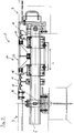
- FIG. 1 shows the embodiment of an expansion joint bridging device 1 according to the invention with a lamellar roadway transition 2, which is arranged between two bridge parts 3 for bridging an expansion joint 4.
- trusses 5 of which in Fig. 1 one is shown span the expansion joint 4 and are each in two truss bearings 6, which on two supports 8 of the bridge parts. 3 are mounted, slidably mounted in the longitudinal direction L. The two truss ends 9 protrude into truss boxes 10 of the bridge parts 3.
- a plurality of fins 11 are based on the trusses 5, a plurality of fins 11 are based.
- the fins 11 are slidably mounted on the trusses 5 in the longitudinal direction L and arranged parallel to each other. Between two slats 11 is in each case connected to these elastic sealing sheet 12 for the protection of the expansion joint bridging device 1 below the road surface 13 on which preferably a suitable for driving through vehicles road surface in the sense of a drivable surface, especially from moisture and dirt ,
- the slat tops 14 extend at the same height as the road surface 13.
- the slidable slide bearings 15 surround the trusses frame-shaped, each arranged between the frame of the slat bearing 15 and the cross member 5 slide blocks and each below between the frame of the slat bearing 15 and the cross member 5 Gleitfederblöcke are.
- the lamellae 11 may be connected to each other (in the sense of a distance control) via mechanical distance controllers, not shown, by means of which the shifting behavior of the lamellae 11 relative to one another can be controlled with a force acting on them in the longitudinal direction L.
- the movement of the left and right outermost fins 11 is limited in the longitudinal direction L on one side by the edge profiles (projections 16) of the bridge parts 3 and the (7 as stops with the lower portions of the frame of the finned bearings 15) spacer.
- the expansion joint bridging device draws on the well-known prior art, so that it neither in terms of the design, nor in terms of the intended function (compensation of thermal expansion or shrinkage of the bridge parts 3 by changing the distances between the on slats 11) displaceably mounted on the traverses require further explanation in the design or work area.
- an overload safety device 17 is arranged, wherein the gaps between the overload fuse device 17 and the adjacent thereto lamellae 11 are closed by geomembranes 12.
- the - displaceable in the longitudinal direction L - overload safety device 17 has two mutually spaced longitudinally L support profiles 18 and arranged between them, the gap S between the two support sections 18 bridging filling profile 32, wherein in normal operation, a the Location of these parts securing each other securing acts.
- the two support profiles 18 include, in a certain static reference to the slats 11, each a profile head 19, a profile base 20 and a welded to both profile web 21, wherein additional, welded to said three parts of the support profiles stiffening elements 22 each having a sloping stiffening side surface 23 are provided.
- each support profile 18 (described in more detail below) supporting profile bearings, which are connected via a pair of first screw 26 with the profile feet 20 and in particular two each in the longitudinal direction L on the cross member 5 slidable sliding blocks 25 include.
- the profile heads 19 have in the direction of the adjacent slats 11 extending hook 27.
- Guide elements 28 extending in the same direction are firmly connected to the profile head tops 29 of the (substantially cuboid) profile heads 19. Between the hooks 27 and the Guide elements 28 are in respective cavities, the geomembranes 12 firmly clamped edge. All slats 11 have the upper guide elements 28 similar Verklemm drivingen 30 and hooks 27, whereby the geomembrane webs 12 can be clamped both between two slats 11, and between slats 11 and support sections 18.
- the filling profile 32 has a plate 33 and a base 34 connected thereto.
- the outer left and right edge portions 59 of the plate 33 of the filling profile 32 are on the support portions forming profile top 29 of the profile heads 19, wherein the support profiles 18 relative to the plate 33 of the filling profile 32 are sealed by means of sealing pads 58.
- the profile heads 19 of the support profiles 18 are fastened to the filling profile 32 by a pair of second screw connections 31, which form part of the upper of two parts of the fixing device and are designed as breakaway screw connections.
- the plate top 35 of the plate 33 extends at the same height as the road surface 13.
- the obliquely extending plate side surfaces 36 of the plate 33 abut corresponding oblique guides 37 of the guide elements 28.
- the base 34 of the filling profile 32 comprises a web, a Golfprofilfuß 40 and with these parts and the plate 33 welded stiffeners, the latter having inclined, downwardly converging base sides 38.
- a Golfprofilfuß 40 At the Artprofilfuß 40 is a Golfprofillager 41, which slidably rests in the longitudinal direction L on the crossbar 5 and is identical to the sliding blocks 25.
- the second screw 31 are tightened so tight that the filling profile 32 is clamped by means of Golfprofillager 41 relative to the trusses 5.
- the Greprofilfuß 40 By a pair of third screw 42, the Grezier 41 is firmly connected to the Grefuß 40 of the base 34 respectively.
- FIG. 3 shows in a sectional view according to section AA FIG. 1 in particular the supporting profile bearing, which is similar in its basic structure to the partially visible lamella bearings 15.
- the profile foot 20 of the support section 18 is fixedly connected to the cross member 5 encompassing frame 43, which prevents the support section 18 in the sense of a lift-out of an unwanted movement in the height direction H upwards.
- the frame 43 has two elongate side parts 44 and fixedly connected to these flanges 45, which are fixedly connected to the profile base 20 via the first screw 26. At the top, the frame 43 is closed by the bearing plate 46 arranged between the flanges 45 and the profile foot 20.
- the two associated slide blocks 25 are arranged, which rest on the upper Traversesflansch 52 slidably.
- the side parts 44 are fixedly connected to the bottom part 47.
- a cross-sectionally T-shaped spacer element 48 which extends below the traverse 5 and forms the lower of the two parts of the fixing device, is connected to the two support profiles 18 associated frame 43 by each of the bottom part 47 of the frame 43 via a pair of fourth screw 49 is attached.
- the fourth screw connections represent predetermined-breaking screw connections.
- expansion joint bridging device 1 has a single blade 11.
- the support profiles 18 and the filling profile 32 of the overload safety device 17 are based on the trusses 5 from.
- the gap between the right-hand projection 16 of the right-hand bridge part 3 and the overload-securing device 17 is closed by a geomembrane 12 which, however, is not adapted to receive forces, in particular in the longitudinal direction L of the crossmember 5.
- the gap between the left projection 16 of the left bridge part 3 and the overload safety device 17 is closed by the single lamella 11 and two sealing lanes 12 having the aforementioned properties.
- FIGS. 6 and 7 show an embodiment of the above-described overload safety devices 17 with serving as a predetermined breaking fasteners screw 60 on the filling profile 32 screwed frame 57, which completely surround the trusses 5.
- the frames 57 of the filling profile 32 have the same elements as the frame 43 of the support profiles 18.
- the sliding spring 58 exerts a spring force on the lower truss flanges 61 and the bottom parts 62 of the frame 57, whereby the filling profiles 32 braced by means of the Greprofillager 41 against the trusses 5 become.
Landscapes
- Engineering & Computer Science (AREA)
- Architecture (AREA)
- Civil Engineering (AREA)
- Structural Engineering (AREA)
- Bridges Or Land Bridges (AREA)
- Road Paving Structures (AREA)
- Building Environments (AREA)
- Buildings Adapted To Withstand Abnormal External Influences (AREA)
Description
Die Erfindung betrifft eine Dehnfugen-Überbrückungsvorrichtung in Form eines Lamellen-Fahrbahnübergangs, welcher eine zwischen zwei Bauwerksteilen eines befahrbaren Bauwerks bestehende Dehnfuge überbrückt, welche von mindestens zwei Traversen überspannt wird. Letztere stützen sich an beiden Bauwerksteilen lasttragend ab, wobei mindestens eine der lasttragenden Abstützungen eine Verschiebebewegung der jeweiligen Traverse relativ zu dem betreffenden Bauwerksteil gestattet. An den Traversen stützt sich mindestens eine oberhalb der Traversen angeordnete Lamelle relativ zu den Traversen verschiebbar ab, wobei mehrere Lamellen zumindest im Wesentlichen parallel zueinander orientiert und auch relativ zueinander verschiebbar sind. An Brücken und vergleichbaren befahrbaren Bauwerken sind zwischen Widerlager und Überbau und/oder zwischen Teilabschnitten des Überbaus Dehnfugen vorgesehen, um eine beschädigungsfreie thermische Ausdehnung bzw. Kontraktion des Überbaus zu ermöglichen. Je nach Größe entsprechender Brücken sind Dehnfugen im Bereich bis zu einigen Metern erforderlich. Um das Überfahren der betreffenden Dehnfugen durch Fahrzeuge zu ermöglichen, sind Dehnfugen-Überbrückungsvorrichtungen vorgesehen.The invention relates to an expansion joint bridging device in the form of a lamellar roadway transition, which bridges an existing between two structural parts of a navigable structure expansion joint, which is spanned by at least two trusses. The latter are based on both structural parts load-bearing, at least one of the load-bearing supports a sliding movement of the respective traverse relative to the relevant part of the building permits. At least one lamella arranged above the trusses is displaceably supported on the trusses relative to the trusses, with a plurality of lamellae being oriented at least substantially parallel to one another and also being displaceable relative to one another. At bridges and comparable navigable structures expansion joints are provided between the abutment and superstructure and / or between sections of the superstructure to allow a damage-free thermal expansion or contraction of the superstructure. Depending on the size of the bridges, expansion joints in the range of up to several meters are required. In order to allow the crossing of the respective expansion joints by vehicles, expansion joint bridging devices are provided.
Bekannt ist insoweit insbesondere der Einsatz von Lamellen-Fahrbahnübergängen, bei denen zwei Brückenteile (in diesem Sinne gilt auch das Widerlager als ein "Brückenteil") durch wenigstens zwei zueinander beabstandete Traversen derart miteinander verbunden sind, dass die einander zugewandten Enden betreffender Brückenteile eine Relativbewegung in Längsrichtung der Traversen aufeinander zu und voneinander weg durchführen können. Auf den Traversen stützen sich einander beabstandete, relativ zueinander bewegliche und im Wesentlichen quer zur Längsrichtung der Traversen verlaufende Lamellen ab, deren jeweilige Oberseite im Wesentlichen auf der Höhe der Fahrbahn der Brücke liegen bzw. diese bilden kann, wobei allerdings auch Ausführungen bekannt sind, bei denen an den Lamellen an deren Oberseite gesonderte, die befahrbare Oberfläche bildende Elemente angeordnet sind. Bewegen sich die Enden der Brückenteile aufgrund einer thermischen Ausdehnung in Längsrichtung der Traversen aufeinander zu, so verringert sich der Abstand der Lamellen zueinander. Bewegen sich die Enden der Brückenteile aufgrund einer thermischen Schrumpfung in Längsrichtung voneinander weg, so erhöht sich der Abstand der Lamellen zueinander. Einschlägigen Stand der Technik bilden insoweit beispielsweise die
In durch Erdbeben gefährdeten Regionen besteht die Gefahr abrupt auftretender Positionsänderungen der Brückenteile zueinander (insbesondere in Längsrichtung der Traversen bzw. mit einer solchen Bewegungskomponente), welche, indem sie den bestimmungsgemäßen Arbeitsbereich überschreiten, unter Umständen nicht mehr durch Lamellen-Fahrbahnübergange kompensiert werden können. Es ist dann möglich, dass sich die Brückenteile über die normalen thermischen Längenausdehnungen hinaus derart in Längsrichtung aufeinander zu bewegen, dass die Lamellen bei bestimmten Positionen der Brückenteile zunächst aneinander anliegen und eine weitere Bewegung der Brückenteile aufeinander zu Eigenspannungen und möglicherweise Schäden in den Lamellen bzw. Brückenteilen zur Folge hat. In solchen Fällen muss nicht nur damit gerechnet werden, dass nach dem Erdbeben eine Befahrbarkeit der Brücke durch Fahrzeuge nicht mehr gewährleistet ist; vielmehr können die Schäden an den Brückenteilen und/oder der Dehnfugen-Überbrückungsvorrichtung solchermaßen ausgeprägt sein, dass eine gänzliche Neuherstellung der Brücke erforderlich ist.In regions endangered by earthquakes, there is the danger of abruptly occurring position changes of the bridge parts to one another (in particular in the longitudinal direction of the trusses or with such a movement component) which, by exceeding the intended working range, may no longer be compensated by lamellar roadway transitions. It is then possible for the bridge parts to move toward one another in the longitudinal direction beyond the normal thermal length expansions such that the lamellae initially abut each other at certain positions of the bridge parts and further movement of the bridge parts toward each other results in residual stresses and possibly damage in the lamellae or Bridge parts result. In such cases, it must not only be expected that the bridge will no longer be navigable by vehicles after the earthquake; rather, the damage to the bridge members and / or the expansion joint bridging device may be so pronounced that a complete remake of the bridge is required.
Nach
Letzteres trifft auf für die Dehnfugen-Überbrückungsvorrichtung nach der
Die
Die weiter oben im Zusammenhang mit der
Aufgabe der Erfindung ist es daher eine verbesserte, funktionsoptimerte Dehnfugen-Überbrückungsvorrichtung der eingangs genannten Art derart zu schaffen, die auch durch Erdbeben verursachten Positionsänderungen zweier überbrückter Brückenteile optimal standhält und beste Voraussetzungen für eine Befahrbarkeit nach dem Erdbeben bzw. eine deutlich vereinfachte Instandsetzung mit geringst möglichem Aufwand bietet.The object of the invention is therefore to provide an improved, functionally optimized expansion joint bridging device of the type mentioned above, which also optimally withstands earthquake position changes of two bridged bridge parts and best conditions for passability after the earthquake or a much easier repair with the lowest possible Effort offers.
Die Aufgabe wird durch die Dehnfugen-Überbrückungsvorrichtung nach Anspruch 1 gelöst. Dieser betrifft die Umsetzung der Erfindung bei einer bestimmungsgemäß für einen geringen Arbeitsbereich (eine geringe Spaltweite) ausgelegten Dehnfugen-Überbrückungsvorrichtung, die zusätzlich zu der bezeichneten Überlast-Sicherungseinrichtung nur eine einzige Lamelle aufweist, so dass die Dehnfuge durch die eine Lamelle und die - mit keinem Bauwerksteil fest verbundene - Überlast-Sicherungseinrichtung überbrückt wird. Solche Dehnfugen-Überbrückungsvorrichtungen lassen sich beispielsweise vorteilhaft dort einsetzen, wo thermische Ausdehnungen bzw. Kontraktionen von niedriger und die Gefahr abrupt auftretender Positionsänderungen der Bauwerksteile zueinander von hoher Relevanz sind. Bei Umsetzung der Erfindung für einen größeren Arbeitsbereich stützen sich, wie in Anspruch 2 angegeben, an den Traversen mehrere zumindest im Wesentlichen parallel zueinander orientierte, oberhalb der Traversen angeordnete Lamellen relativ zu den Traversen sowie relativ zueinander verschiebbar ab, wobei in diesem Fall die Überlast-Sicherungseinrichtung zwischen zwei der relativ zu den Traversen sowie relativ zueinander verschiebbaren Lamellen vorgesehen ist. Die nachfolgende Erläuterung der Erfindung reflektiert auf deren Umsetzung bei solchen, mehrere Lamellen aufweisenden Dehnfugen-Überbrückungsvorrichtungen; die dargelegten Gesichtspunkte gelten aber auch für bestimmungsgemäß für einen geringen Arbeitsbereich (eine geringe Spaltweite) ausgelegte Dehnfugen-Überbrückungsvorrichtungen, die zusätzlich zu der bezeichneten Überlast-Sicherungseinrichtung nur eine einzige Lamelle aufweisen.The object is achieved by the expansion joint bridging device according to
Gemäß den Ansprüchen zeichnet sich die erfindungsgemäße Dehnfugen-Überbrückungsvorrichtung in funktioneller Kombination mit den übrigen Konstruktionsmerkmalen insbesondere dadurch aus, dass zwischen zwei der relativ zu den beiden Bauwerksteilen, zu den Traversen sowie zueinander verschiebbaren Lamellen eine Überlast-Sicherungseinrichtung vorgesehen ist, welche zwei zueinander beabstandete, sich auf den Traversen abstützende Stützprofile und ein den Spalt zwischen den Stützprofilen überbrückendes Füllprofil umfasst. Zwischen den beiden Stützprofilen wirkt dabei eine deren relative Lage zueinander sichernde Fixiereinrichtung, welche bei Überschreiten eines Schwellenwerts für die auf die beiden Stützprofile im Sinne von deren Annäherung wirkende Kraft die Lagesicherung dergestalt freigibt, dass die beiden Stützprofile unter Verdrängung des Füllprofils nach oben aus dem Spalt heraus aufeinander zu bewegbar sind.According to the claims, the expansion joint bridging device according to the invention in functional combination with the other design features is characterized in particular by the fact that between two of the relative to the two structural parts, the trusses and mutually displaceable slats an overload safety device is provided, which two spaced apart, includes support profiles supported on the trusses and a filling profile bridging the gap between the support profiles. Between the two support profiles acts while a relative position to each other securement fixing, which releases the position assurance when a threshold value for acting on the two support profiles in the sense of their approach force such that the two support profiles under displacement of the filling profile up out of the gap out to each other are movable.
Die Überlast-Sicherungseinrichtung kann an beliebigen Positionen der Überbrückungsvorrichtung, d.h. zwischen zwei beliebigen der Lamellen angeordnet sein, namentlich, insbesondere wenn "nur" eine Überlast-Sicherungseinrichtung vorgesehen ist, auch mehr oder weniger mittig an der Überbrückungsvorrichtung. Diese äußerst flexible Anordbarkeit der Überlast-Sicherungseinrichtung innerhalb der Dehnfugen-Überbrückungsvorrichtung leistet gegenüber der bekannten Anordnung am Rand eines Brücken- bzw. Bauwerksteils einen Beitrag dazu, die Sicherheit gegenüber bei Erdbeben auftretenden Stoßkräften zu erhöhen. Letztere werden bei am Rand eines Brückenteils angeordneten Überlast-Sicherungseinrichtungen direkt auf diese übertragen und können zu deren Zerstörung bzw. Beschädigung führen. Eine "innere" Anordnung der Überlast-Sicherungseinrichtungen zwischen zwei der Lamellen hat demgegenüber den Vorteil, dass seismische Stoßkräfte zuerst auf die Lamellen übertragen werden und die Lamellenpakete zusammenschieben. Erst wenn alle (in Stoßrichtung) vor der Überlast-Sicherungseinrichtung angeordneten Lamellen aneinander anliegen, werden Kräfte auf die Stützprofile der Überlast-Sicherungseinrichtung übertragen. Die Lamellen erfüllen damit eine Pufferfunktion gegenüber auftretenden Stoßkräften, indem diese in Längsrichtung zuerst auf die Lamellen wirken und die Überlast-Sicherungseinrichtung nur bei einer außergewöhnlich großen Kraft, verursacht z.B. durch ein Erdbeben, ausgelöst wird. Die Einbettung der Überlast-Sicherungseinrichtung innerhalb der Lamellen der Überbrückungsvorrichtung begünstigt außerdem - wegen der hierdurch ermöglichten mehr oder weniger ausgeprägten Symmetrie der Belastungssituation - das Auslösen der Überlast-Sicherungseinrichtung tatsächlich ausschließlich in dem hierfür vorgesehenen Auslegungsfall, was für die Befahrbarkeit der Überbrückungsvorrichtung nach unterhalb des Auslegungsfalls liegenden tektonischen Erschütterungen von größtem Vorteil ist. Auch für die Funktion der Überlast-Sicherungseinrichtung selbst ist deren "innere" Anordnung zwischen zwei der Lamellen von großem Nutzen; denn das Füllprofil kann gleichmäßig und seitlich unverkantet aus dem Spalt zwischen den Stützprofilen herausgehoben werden, weil die Anordnung in der Mitte der Dehnfugen-Überbrückungsvorrichtung einen besonders symmetrischen Kraftangriff an der den Stützprofilen ermöglicht.The overload safety device can be arranged at arbitrary positions of the lockup device, ie between any two of the slats, namely, in particular if "only" an overload safety device is provided, also more or less centrally on the lockup device. This extremely flexible arrangeability of the overload safety device within the expansion joint bridging device achieves the known arrangement at the edge of a bridge or structural part a contribution to increasing safety against earthquake-related impact forces. The latter are transmitted directly to these arranged on the edge of a bridge part overload safety devices and can lead to their destruction or damage. An "internal" arrangement of overload protection devices between two of the slats has the advantage that seismic impact forces are first transmitted to the slats and push the disk packs together. Only when all (in shock direction) arranged in front of the overload safety device lamellae abut each other, forces are transmitted to the support profiles of the overload safety device. The lamellae thus fulfill a buffer function against occurring impact forces by acting in the longitudinal direction first on the lamellae and the overload safety device only at an exceptionally large force, caused for example by an earthquake, is triggered. The embedding of the overload safety device within the slats of the lock-up device also favors - due to the thus enabled more or less pronounced symmetry of the load situation - the triggering of the overload safety device actually only in the design case provided for this, which for the passability of the lock-up device below the design case lying tectonic vibrations is of great advantage. Also for the function of the overload protection device itself is their "inner" arrangement between two of the slats of great use; because the filling profile can be lifted evenly and laterally unverkantet from the gap between the support profiles, because the arrangement in the middle of the expansion joint bridging device allows a particularly symmetrical force application to the support profiles.
Die Überlast-Sicherungseinrichtung umfasst zwei äußere Stützprofile, welche auf den Traversen gelagert sind, und ein zwischen den Stützprofilen angeordnetes Füllprofil, das fahrbahnseitig die Lücke zwischen den Stützprofilen schließt. Die Oberseite des Füllprofils (ggf. samt zugeordneter Auflagen) sollte im nicht ausgelösten Zustand der Überlast-Sicherungseinrichtung auf gleicher Höhe mit der Oberseite der Lamellen und den Oberseiten der Stützprofile (ggf. jeweils samt zugeordneter Auflagen) liegen, um eine möglichst ebene Abrollfläche für über die Dehnfugen-Überbrückungsvorrichtung fahrende Fahrzeuge zu gewährleisten. Das - beim Auslösen der Überlast-Sicherungseinrichtung erfolgende - Heraustreten des Füllprofils nach oben aus dem zwischen den Stützprofilen bestehenden Spalt kann sich konstruktiv in verschiedener Weise vollziehen. In Betracht kommt insbesondere, dass das Füllprofil als Ganzes ohne Änderung seiner Geometrie nach oben aus dem Spalt verdrängt wird. Indessen kommt auch in Betracht, dass das Füllprofil, wenn es nach oben aus dem zwischen den Stützprofilen bestehenden Spalt verdrängt wird, seine Geometrie ändert, beispielsweise indem ein aus mehreren gelenkig miteinander verbundenen Segmenten bestehendes Füllprofil nach oben gefaltet wird.The overload safety device comprises two outer support profiles, which are mounted on the trusses, and a filling profile arranged between the support profiles which closes the gap between the support profiles on the roadway side. The top of the filling profile (possibly with associated conditions) in the untripped condition of the overload safety device should be at the same level as the upper side of the lamellae and the upper sides of the support profiles (possibly together with associated supports) in order to provide as even a level rolling surface as possible To ensure the expansion joint bridging device moving vehicles. The - when triggering the overload safety device takes place - emergence of the filling profile upwards from the gap existing between the support profiles can constructively take place in various ways. In particular, it comes into consideration that the filling profile as a whole is displaced upwards out of the gap without changing its geometry. However, it is also contemplated that the filling profile, when displaced upwardly out of the gap between the support profiles, changes its geometry, for example by folding a filling profile consisting of a plurality of hingedly interconnected segments.
Eine Fixiereinrichtung sorgt (im "normalen" Betriebszustand) für eine Lagesicherung der Stützprofile zueinander (in Längsrichtung der Traversen). Die Festigkeit dieser Lagesicherung definiert einen Schwellenwert für Kräfte, welche auf die Stützprofile wirken, oberhalb dessen die durch die Fixiereinrichtung bewirkte Lagesicherung aufgehoben wird und die Stützprofile sich in Längsrichtung aufeinander zu bewegen können. Bei einer solchen Bewegung wird das Füllprofil nach oben aus dem Spalt zwischen den beiden Stützprofilen heraus verdrängt (s.o.), wodurch sich die Stützprofile, die ihrerseits eine lamellenartige Funktion haben, entsprechend weiter aufeinander zu bewegen können und somit sich die gesamte Erstreckung der auf den Traversen aufliegenden Teilstruktur der Dehnfugen-Überbrückungsvorrichtung in Längsrichtung weiter verkleinern lässt, ohne dass diese aufgrund zu hoher Eigenspannungen zerstört wird. Der genannte Schwellenwert kann, wie weiter oben bereits angedeutet, bei der erfindungsgemäßen Anordnung der Überlast-Sicherheitseinrichtung aufgrund der Pufferfunktion der Lamellen und der möglichen Symmetrie der Belastungssituation geringer dimensioniert bzw. präziser ausgelegt werden als bei einer Anordnung am Rand eines Brückenteils, wodurch Material, Gewicht und Kosten eingespart werden können und die Funktion der Überlast-Sicherheitseinrichtung verbessert werden kann.A fixing device ensures (in the "normal" operating state) for a position securing the support profiles to each other (in the longitudinal direction of the trusses). The strength of this position assurance defines a threshold for forces acting on the support profiles, above which the position assurance effected by the fixing device is canceled and the support profiles can move towards one another in the longitudinal direction. In such a movement, the filling profile is displaced upwards out of the gap between the two support profiles (see above), whereby the support profiles, which in turn have a lamellar function, can continue to move towards each other and thus the entire extent of the on the trusses Lying further subjacent substructure of the expansion joint bridging device in the longitudinal direction without these due is destroyed to high residual stresses. As already indicated above, said threshold value can be dimensioned smaller or more precisely in the inventive arrangement of the overload safety device due to the buffer function of the lamellae and the possible symmetry of the loading situation than in the case of an arrangement at the edge of a bridge part, whereby material, weight and costs can be saved and the function of the overload safety device can be improved.
Sofern nach einem seismischen Ereignis dauerhaft eine Änderung der Position der Bauwerksteile verbleibt, kann ggf. die Dehnfugen-Überbrückungseinrichtung mit minimalem Aufwand allein durch Einbau eines an die neue Situation angepassten Füllprofils so hergerichtet werden, dass die Überbrückungseinrichtung nicht nur provisorisch, sondern vielmehr dauerhaft funktionssicher ist.If, after a seismic event, a permanent change in the position of the structural parts remains, the expansion joint bridging device can be prepared with minimal effort alone by installing a customized to the new situation filling profile so that the bridging device is not only provisional, but rather permanently reliable ,
Die vorliegende Erfindung gestattet im Übrigen, mehrere (funktional gleichwirkende) Überlast-Sicherheitseinrichtungen - insbesondere mehr oder weniger gleichmäßig über die Erstreckung der Dehnfugen-Überbrückungsvorrichtung verteilt - in letztere zu integrieren. Dies eröffnet weitergehende Möglichkeiten der Anpassung der Sicherheitseinrichtung(en) an die - durch Auswertung der tektonischen Situation - zu erwartenden seismischen Ereignisse. Es ist ferner möglich, zwei oder mehrere Überlast-Sicherungseinrichtung direkt nebeneinander zwischen zwei einander benachbarten Lamellen anzuordnen, wobei in diesem Fall ggf. ein beiden Überlast-Sicherungseinrichtungen gemeinsames mittleres Stützprofil vorgesehen sein kann. Dabei können bei freigegebener Lagesicherung auch Quer- und Höhenversätze zwischen den Brückenteilen besser zumindest teilweise kompensiert werden, indem die Versätze auf mehrere Überlast-Sicherungseinrichtung aufgeteilt werden.Incidentally, the present invention allows multiple (functionally equivalent) overload safety devices - in particular more or less evenly distributed over the extension of the expansion joint bridging device - to be integrated into the latter. This opens up further possibilities of adapting the safety device (s) to the seismic events to be expected by evaluating the tectonic situation. It is also possible to arrange two or more overload safety device directly adjacent to each other between two adjacent lamellae, in which case, if appropriate, a two overload protection devices common middle support profile can be provided. It can also be better compensated at least partially in transverse position and height offsets between the bridge parts with released position assurance by the offsets are divided into several overload safety device.
Die beiden Stützprofile sind typischerweise gleitend verschiebbar auf den Traversen abgestützt, wobei dergleichen indessen nicht unbedingt zwingend ist. Denkbar ist nämlich auch, dass eines der Stützprofile mit einer oder mehreren (ggf. sämtlichen) Traversen fest verbunden ist. In Betracht kommt sogar auch, dass beide Stützprofile dergestalt wechselweise mit Traversen fest verbunden sind, dass nicht an einer Traverse beide Stützprofile fixiert sind.The two support profiles are typically slidably supported on the trusses, but the like is not necessarily mandatory. It is also conceivable that one of the support profiles with one or more (possibly all) trusses is firmly connected. It is even considered that both support profiles are alternately connected in such a way with trusses that are not fixed to a cross member both support profiles.
In einer ersten Weiterbildung der Erfindung ist vorgesehen, dass das Füllprofil ein Teil der Fixiereinrichtung ist. Hierdurch kann Material für ein gesondertes der Lagesicherung dienendes Bauteil eingespart werden. Die Stützprofile sind in diesem Falle mit dem Füllprofil beidseitig fest verbunden. Das Füllprofil dient als Abstandshalter zwischen den Stützprofilen. Es kann eine effektive Lagesicherung mit einer Kraftverteilung auf beide Seiten der Fixiereinrichtung erzielt und ein Beitrag dazu geleistet werden, dass sich das Füllprofil gleichmäßig aus dem Spalt zwischen den Stützprofilen heraus bewegen kann. Dabei ist es vorteilhaft, wenn das Füllprofil mit den Stützprofilen mittels eine definierte Bruchkraft aufweisenden Sollbruch-Verbindungselementen, z.B. in Form einer Schraub- oder Nietverbindung oder einer Schweißnaht, verbunden ist. Solche Verbindungen sind besonders kostengünstig und zuverlässig zu berechnen.In a first development of the invention, it is provided that the filling profile is part of the fixing device. As a result, material for a separate the position assurance serving component can be saved. The support profiles are firmly connected on both sides in this case with the filling profile. The filling profile serves as a spacer between the support profiles. An effective position assurance can be achieved with a force distribution on both sides of the fixing device and a contribution can be made to the fact that the filling profile can move uniformly out of the gap between the support profiles. It is advantageous if the filling profile with the support profiles by means of a predetermined breaking force having predetermined breaking connection elements, e.g. in the form of a screw or rivet connection or a weld, is connected. Such compounds are particularly inexpensive and reliable to calculate.
In einer weiteren Ausführungsform ist vorgesehen, dass Teile der Stützprofile zur Lagerung des Füllprofils genutzt werden, indem das Füllprofil mit Randbereichen auf Stützbereichen der Stützprofile aufliegt. Durch diese Anordnung kann bei freigegebener Lagesicherung, d.h. beim Auslösen der Überlast-Sicherheitseinrichtung das Verdrängen des Füllprofils erleichtert und Material für eine zusätzliche Lagerung eingespart werden. Für letztgenannte Ausführungsform kann des Weiteren vorteilhaft eine dichtende Auflage der Randbereiche des Füllprofils auf den Stützbereichen der Stützprofile vorgesehen sein. Eine solche dichtende Auflage kann z.B. aus einer Gummidichtung bestehen, durch die besonders wirksam ein Eindringen von Flüssigkeit und Schmutz in den Zwischenraum zwischen den Stützprofilen verhindert werden kann, was namentlich dem Schutz der Traversen und dem Erhalt der Gleitfähigkeit der Lamellen auf diesen zugute kommt.In a further embodiment it is provided that parts of the support profiles are used for the storage of the filling profile by the filling profile rests with edge regions on support areas of the support profiles. By this arrangement can be facilitated in released position assurance, ie when triggering the overload safety device, the displacement of the filling profile and material for additional storage can be saved. Furthermore, for the last-mentioned embodiment, a sealing support of the edge regions of the filling profile can advantageously be provided on the support regions of the support profiles. Such a sealing pad can For example, consist of a rubber seal, can be prevented by the particularly effective penetration of liquid and dirt into the space between the support profiles, which is especially the protection of the trusses and the preservation of the slidability of the slats on this benefit.
In einer weiteren Ausführungsform ist vorgesehen, dass an dem Füllprofil und/oder den Stützprofilen Gleitschrägen vorgesehen sind, welche das Anheben des Füllprofils bei aufeinander zu bewegten Stützprofilen begünstigen. Diese Gleitschrägen stellen ein besonders einfaches und effektives Mittel dar, um durch die Längsbewegung der Stützprofile eine geführte Bewegung des Füllprofils nach oben zu bewirken. Dabei ist die Anordnung korrespondierender Gleitschrägen im Bereich der Auflage des Füllprofils an den Stützprofilen und dem Füllprofil besonders vorteilhaft, weil somit unmittelbar nach Freigabe der Lagesicherung eine geführte Bewegung des Füllprofils erreicht werden kann. Zusätzlich ist es sinnvoll, den Freiraum innerhalb des Spalts zwischen den Stützprofilen für ein weiteres Gleitprofil zu nutzen, welches an einem Teil des Füllprofils angeordnet sein und sich über eine Länge erstrecken kann, die im Bereich der Höhe der Stützprofile liegt. Bei korrespondierend ausgestalteten Gegenstücken an den Stützprofilen kann dadurch eine geführte Gleitbewegung des Füllprofils über nahezu den gesamten Bewegungsbereich des Füllprofils erreicht werden.In a further embodiment it is provided that slip slopes are provided on the filling profile and / or the support profiles, which promote the lifting of the filling profile in mutually moving support profiles. These sliding slopes represent a particularly simple and effective means for effecting a guided movement of the filling profile upwards by the longitudinal movement of the support profiles. In this case, the arrangement of corresponding sliding bevels in the region of the support of the filling profile on the support profiles and the filling profile is particularly advantageous, because thus a guided movement of the filling profile can be achieved immediately after release of the position assurance. In addition, it makes sense to use the space within the gap between the support profiles for another sliding profile, which can be arranged on a part of the filling profile and extend over a length which lies in the region of the height of the support profiles. With correspondingly configured counterparts on the support profiles, a guided sliding movement of the filling profile can thus be achieved over almost the entire range of movement of the filling profile.
In einer weiteren vorteilhaften Ausführungsform der Erfindung stützt sich das Füllprofil (im "normalen" Betriebszustand der Überbrückungsvorrichtung) auf den Traversen ab. Insbesondere weil das Füllprofil typischerweise eine in Längsrichtung der Traversen wesentlich größere Ausdehnung als die Lamellen aufweist, ist eine solche Zwischenlagerung sinnvoll, um eine Durchbiegung des sich im Bereich der Fahrbahn befindlichen länglichen oberen Teils des Füllprofils zu verringern.In a further advantageous embodiment of the invention, the filling profile (in the "normal" operating state of the bridging device) is supported on the trusses. In particular, because the filling profile typically has a significantly greater extent than the lamellae in the longitudinal direction of the traverses, such intermediate storage is useful in order to reduce deflection of the elongated upper part of the filling profile situated in the region of the roadway.
In einer konstruktiven Ausgestaltung dieser Ausführungsform ist das Füllprofil in vorstehend erläuterter Weise durch Sollbruch-Verbindungselemente mit den Stützprofilen verbunden, wobei die Sollbruch-Verbindungsmittel eine Verspannung des Füllprofils gegenüber den Traversen herstellen. Damit kann ohne größeren baulichen Mehraufwand ein stetiger Kontakt zwischen dem Füllprofil und den Traversen gewährleistet und somit die Sicherheit gegen Verkanten erhöht werden. Dabei ist vorzugsweise vorgesehen, dass das Füllprofil mit einem Gleitlager auf der Traverse aufliegt. Durch vorstehend erläuterte Verspannung kann auch bei Abnutzung des Gleitlagers dauerhaft gewährleistet werden, dass dieses stets auf den Traversen aufliegt. In einer weiteren konstruktiven Ausgestaltung dieser Ausführungsform sind dem Füllprofil die Traversen umgreifende Rahmen zugeordnet, welche eine Gleitfeder, die das Füllprofil gegenüber den Traversen verspannt, und wenigstens eine Sollbruchstelle, z.B. in Form einer Schraubverbindung, aufweisen. Vorzugsweise ist die Gleitfeder einseitig mit jeweils einem Bodenteil eines Rahmens verbunden, während die andere Seite der Gleitfeder gleitfähig in Berührung mit der Unterseite der Traverse steht. Außerdem liegt das Füllprofil vorzugsweise mit einem Gleitlager auf der Traverse auf. Hierdurch kann ein stetiger Kontakt zwischen dem Füllprofil und den Traversen erreicht werden, ohne dass höhere Eigenspannungen innerhalb des Füllprofils erzeugt werden.In a constructive embodiment of this embodiment, the filling profile is connected in the manner explained above by predetermined breaking connecting elements with the support profiles, wherein the predetermined breaking connecting means produce a tension of the filling profile relative to the trusses. This can ensure a constant contact between the filling profile and the trusses without major structural overhead and thus increase the security against tilting. It is preferably provided that the filling profile rests with a sliding bearing on the crossbar. Due to the above-explained bracing can be permanently ensured even with wear of the sliding bearing, that this always rests on the trusses. In a further constructional embodiment of this embodiment, the filling profile is associated with the frames encompassing the trusses, which frame comprises a sliding spring which clamps the filling profile with respect to the trusses and at least one predetermined breaking point, e.g. in the form of a screw connection. Preferably, the sliding spring is connected on one side with a respective bottom part of a frame, while the other side of the sliding spring is slidably in contact with the underside of the traverse. In addition, the filling profile is preferably on a slide bearing on the traverse. As a result, a continuous contact between the filling profile and the trusses can be achieved without higher internal stresses being generated within the filling profile.
Weiterhin ist es, sofern eine Überlast-Sicherungseinrichtung vorgesehen ist, vorteilhaft, wenn diese in der Mitte des Lamellen-Fahrbahnübergangs angeordnet ist. Auf beiden Seiten der Stützprofile befinden sich dann bei einer geraden Gesamtanzahl an Lamellen idealerweise gleich viele Lamellen. Bei einer ungeraden Gesamtanzahl an Lamellen befindet sich dementsprechend auf einer Seite der Stützprofile eine Lamelle mehr als auf der anderen Seite. In dieser Ausführungsform wirkt die Überlast-Sicherheitseinrichtung wie eine symmetrische Trennung für die Lamellenpakete. Somit kann eine quasi durch die Überlast-Sicherheitseinrichtung zweigeteilte Dehnfugen-Überbrückungsvorrichtung mit einer zumindest annähernd gleichen Anzahl an Lamellen auf beiden Seiten erzeugt werden, wodurch die Verteilung der Bewegungen auf die einzelnen Lamellen und die Langlebigkeit der Dehnfugen-Überbrückungsvorrichtung als ganzes verbessert werden kann.Furthermore, if an overload safety device is provided, it is advantageous if it is arranged in the middle of the louvered roadway transition. On both sides of the support profiles are then ideally with a straight total number of slats equal to many slats. With an odd total number of lamellae is accordingly on one side of the support profiles one lamella more than on the other side. In this embodiment, the overload safety device acts as a symmetrical separation for the disk packs. Thus, a quasi By the overload safety device, a two-part expansion joint bridging device having at least an approximately equal number of fins on both sides can be produced, whereby the distribution of the movements on the individual fins and the longevity of the expansion joint bridging device as a whole can be improved.
Die auf den Traversen mit den Stützprofilen und bevorzugt ebenfalls mit dem Füllprofil aufliegende Überlast-Sicherheitseinrichtung ist zwar, wie weiter oben dargelegt, typischerweise in Längsrichtung der Traversen beweglich, reagiert jedoch aufgrund ihres im Vergleich zu einer Lamelle höheren Eigengewichts mit dazu entsprechend höherer Reibkraft träger als die einzelnen Lamellen. Dadurch wird ein Beitrag geleistet, dass die Lamellen auf beiden Seiten der Stützprofile gleichmäßiger beansprucht werden. In der Regel ist eines der Brückenteile in Längsrichtung der Traversen verschiebbar und das andere in Längsrichtung der Traversen ortsfest gelagert. Im Falle einer Relativbewegung der Brückenteile zueinander, beispielsweise in Form einer thermisch bedingten Längensaudehnung wenigstens eines Brückenteils oder einer Positionsänderung eines Brückenteils, welche nicht zu einer Auslösung der Überlast-Sicherungseinrichtung führen, kann die Überlast-Sicherheitseinrichtung auf ihrer Position relativ zu der Traverse verbleiben, wobei sich die Traversen in Traversenkästen hinein und aus ihnen heraus bewegen können. Im Idealfall werden alle Lamellen gleichermaßen aktiviert und bewegt, indem sich die Relativbewegung auf beiden Seiten der Überlast-Sicherungseinrichtung nahezu gleich auf alle Lamellen verteilt.The on the trusses with the support profiles and preferably also with the filling profile resting overload safety device is, as stated above, typically movable in the longitudinal direction of the traverses, but reacts due to their compared to a slat higher dead weight with correspondingly higher frictional force carrier the individual slats. As a result, a contribution is made that the lamellae are stressed more uniformly on both sides of the support profiles. As a rule, one of the bridge parts is displaceable in the longitudinal direction of the traverses and the other is mounted stationary in the longitudinal direction of the traverses. In the case of a relative movement of the bridge parts to one another, for example in the form of a thermally induced Längensaugehnung least one bridge portion or a change in position of a bridge portion, which do not lead to a triggering of the overload safety device, the overload safety device can remain in position relative to the traverse, said the trusses can move into truss boxes and out of them. Ideally, all slats are equally activated and moved by the relative movement on both sides of the overload safety device almost equally distributed to all slats.
Das Vorsehen einer Aushebesicherung zwischen den Stützprofilen und den Traversen kann einen weiteren Beitrag zur Funktionssicherheit der Überlast-Sicherheitseinrichtung leisten, indem die Sitzsicherheit der Stützprofile auf den Traversen verbessert wird. Eine unerwünschte Ablösung der Stützprofile nach oben kann dadurch verhindert werden. Neben der Verringerung des Risikos einer Ablösung der Stützprofile von den Traversen kann des Weiteren einem Verkanten der Stützprofile wirksam vorgebeugt wird. Ein einwandfreier Sitz der Stützprofile auf den Traversen erleichtert die vorgesehene Bewegung des Füllprofils im Notfall und steigert damit die Funktionssicherheit der Überlast-Sicherheitseinrichtung. In konstruktiver Ausgestaltung einer solchen Aushebesicherung ist vorteilhafterweise jeweils ein Rahmen (mit geringem Abstand um die betreffende Traverse herum) vorgesehen, der an seiner Oberseite mit dem Stützprofil durch eine Schraubverbindung, welche als Sollbruchstelle dient, verbunden sein kann, wobei zwischen dem Rahmen und der jeweiligen Traverse bevorzugt (oben) Gleitblöcke und/oder (unten) Gleitfederblöcke angeordnet sind.The provision of a lift-out between the support profiles and the trusses can make a further contribution to the reliability of the overload safety device by the seat safety of the support profiles is improved on the trusses. An undesirable separation of the support profiles upwards can be prevented. In addition to the reduction Furthermore, the risk of a detachment of the support profiles from the trusses can effectively be prevented from tilting the support profiles. A perfect fit of the support profiles on the trusses facilitates the intended movement of the filling profile in an emergency and thus increases the reliability of the overload safety device. In a constructive embodiment of such a lifting protection is advantageously a frame (at a small distance around the respective traverse around) is provided, which can be connected at its top to the support section by a screw which serves as a predetermined breaking point, wherein between the frame and the respective Traverse preferred (above) sliding blocks and / or (below) Gleitfederblöcke are arranged.
Der Schutz vor Verkanten der Stützprofile kann bei dieser Ausführungsform dadurch noch weiter erhöht werden, dass zwischen den Rahmen der beiden Stützprofile unterhalb der Traversen angeordnete Distanzelemente vorgesehen sind, welche mit den Rahmen mittels Sollbruch-Verbindungselementen verbunden sind. Somit werden beide Stützprofile miteinander gekoppelt, ihr Sitz auf den Traversen weiter versteift und ihr Abstand zueinander nochmals gesichert.The protection against tilting of the support profiles can be further increased in this embodiment, characterized in that between the frame of the two support profiles below the trusses arranged spacer elements are provided, which are connected to the frame by means of predetermined breaking connection elements. Thus, both support profiles are coupled together, their seat further stiffened on the trusses and their distance from each other again secured.
Weiterhin ist das Vorsehen jeweils wenigstens einer Gleitfeder innerhalb der Rahmen vorteilhaft, welche die Stützprofile gegenüber den Traversen verspannen. Genannte Gleitfedern können in besonders einfacher Weise einseitig mit jeweils der unteren Seite eines Rahmens verbunden sein, während die andere Seite der Gleitfeder gleitfähig in Berührung mit der Unterseite der Traverse steht. Gegenüber der wenigstens einen Gleitfeder sollte eine identische Anzahl von Gleitlagern zwischen der oberen inneren Seite des Rahmens und der Oberseite der Traverse angeordnet sein. Vorteilhaft wirken in dieser Anordnung die Federkräfte der Gleitfedern in die gleiche Richtung wie die Massenkräfte der Stützprofile.Furthermore, the provision of at least one sliding spring within the frame is advantageous, which clamp the support profiles relative to the trusses. Said sliding springs can be connected in a particularly simple manner on one side with each of the lower side of a frame, while the other side of the sliding spring is slidably in contact with the underside of the traverse. Compared to the at least one sliding spring, an identical number of plain bearings should be arranged between the upper inner side of the frame and the upper side of the crossbar. Advantageously act in this arrangement, the spring forces of the sliding springs in the same direction as the mass forces of the support profiles.
Dadurch kann die Vorspannung der Gleitfedern und die Trägheit der Überlast-Sicherungseinrichtung in Bezug auf Bewegungen entlang der Traversen und die Sicherheit gegen Verkanten der Stützprofile auf den Traversen weiter erhöht werden. Diese Effekte können durch den Einsatz mehrerer Gleitfedern pro Rahmen und Stützprofil bzw. größere Gleitfedern weiter verstärkt werden, wobei in diesem Fall der Rahmen vorteilhaft eine zur vollständigen Aufnahme der Gleitfedern ausreichende Erstreckung in Längsrichtung L der Traverse aufweisen sollte.Thereby, the bias of the sliding springs and the inertia of the overload safety device with respect to movements along the trusses and the security against tilting of the support profiles on the trusses can be further increased. These effects can be further enhanced by the use of a plurality of sliding springs per frame and support profile or larger sliding springs, in which case the frame should advantageously have sufficient extension in the longitudinal direction L of the traverse for complete reception of the sliding springs.
Des Weiteren ist es vorteilhaft, wenn die Stützprofile und/oder das Füllprofil eine befahrbare Oberfläche auf ihrer fahrbahnseitigen Oberseite aufweisen. Durch diese Ausgestaltung kann die Oberseite des Stützprofils direkt als Fahrbahnbelag für die Brücke dienen, ohne dass noch eine weitere Schicht oder Auflage aufgebracht werden muss, wodurch Material, Gewicht und Kosten eingespart werden können.Furthermore, it is advantageous if the support profiles and / or the filling profile have a drivable surface on its roadside upper side. With this configuration, the top of the support profile can serve directly as a road surface for the bridge, without even a further layer or support must be applied, whereby material, weight and cost can be saved.
In einer Weiterbildung des Erfindungsgegenstands ist vorgesehen, dass die Stützprofile gegenüber benachbarten Lamellen mittels verformbarer Dichtungsbahnen abgedichtet sind, wodurch wirksam verhindert wird, dass an dieser Stelle Feuchtigkeit und Schmutz eindringen und zu den Traversen gelangen kann, was namentlich dem Schutz der Traversen und dem Erhalt der Gleitfähigkeit der Lamellen auf diesen zugute kommt.In a further development of the subject invention, it is provided that the support profiles are sealed against adjacent slats by means of deformable sealing sheets, which effectively prevents moisture and dirt from entering at this point and can reach the trusses, which is especially the protection of the trusses and the preservation of Slidability of the slats on these benefits.
Weiterhin vorteilhaft (insbesondere im Sinne der weiter oben bereits erörterten Symmetrie der Belastungszustände) ist die beidseitige verschiebbare lasttragende Abstützung der Traversen an den Bauwerksteilen. Bevorzugt ragen dabei die Traversen beidseits endseitig in Traversenkästen hinein.Furthermore advantageous (in particular in the sense of the already discussed above symmetry of the loading conditions) is the double-sided sliding load-bearing support of the trusses to the building parts. Preferably, the trusses protrude into traverse boxes on both sides.
Nachfolgend wird ein Ausführungsbeispiel der Erfindung anhand der Zeichnung näher erläutert. Dabei zeigt:
- Fig. 1
- einen parallel zur Richtung der Traversen geführten Schnitt durch eine erfindungsgemäß ausgeführte Dehnfugen-Überbrückungsvorrichtung,
- Fig. 2
- eine vergrößerte Darstellung der Überlast-Sicherheitseinrichtung und der an diese angrenzenden Lamellen gemäß dem Ausschnitt B aus
Fig. 1 , - Fig. 3
- eine Querschnittsansicht der Traverse und der Stützprofillagerung gemäß Schnittführung A-A durch die Überlast-Sicherheitseinrichtung aus
Fig. 1 , - Fig. 4
- einen der Perspektive der
Fig. 1 entsprechenden Schnitt durch die der Dehnfugen-Überbrückungsvorrichtung ausFig. 1 mit ausgelöster Überlast-Sicherungsvorrichtung bei vorgesehenem nahezu minimalem Abstand der Stützprofile zueinander, - Fig. 5
- einen parallel zur Richtung der Traversen geführten Schnitt durch eine erfindungsgemäß ausgeführte Dehnfugen-Überbrückungsvorrichtung mit einer einzigen Lamelle,
- Fig. 6
- einen parallel zur Richtung der Traversen geführten Schnitt durch eine Ausführungsform einer erfindungsgemäß ausgeführten Dehnfugen-Überbrückungsvorrichtung mit einem dem Füllprofil zugeordneten Rahmen,
- Fig. 7
- eine Querschnittsansicht der Traverse und der Füllprofillagerung gemäß Schnittführung durch die Überlast-Sicherungseinrichtung aus
Fig. 6 .
- Fig. 1
- a guided parallel to the direction of the trusses section through an inventively executed expansion joint bridging device,
- Fig. 2
- an enlarged view of the overload safety device and the adjacent thereto lamellae according to the neck B from
Fig. 1 . - Fig. 3
- a cross-sectional view of the traverse and the support profile storage according to section AA through the overload safety device
Fig. 1 . - Fig. 4
- one of the perspective of
Fig. 1 corresponding section through the expansion joint bridging deviceFig. 1 with triggered overload safety device with provided almost minimal distance between the support profiles, - Fig. 5
- a cross-section taken parallel to the direction of the trusses by an inventively executed expansion joint bridging device with a single blade,
- Fig. 6
- a guided parallel to the direction of the trusses section through an embodiment of an inventively executed expansion joint bridging device with a filling profile associated frame,
- Fig. 7
- a cross-sectional view of the traverse and Füllprofillagerung according to cut through the overload safety device
Fig. 6 ,
Mehrere Traversen 5, von denen in
Auf den Traversen 5 stützen sich mehrere Lamellen 11 ab. Die Lamellen 11 sind auf den Traversen 5 in Längsrichtung L gleitfähig gelagert und zueinander parallel angeordnet. Zwischen zwei Lamellen 11 befindet sich jeweils eine mit diesen verbundene elastische Dichtungsbahn 12 zum Schutz der Dehnfugen-Überbrückungsvorrichtung 1 unterhalb der Fahrbahnebene 13, auf der sich vorzugsweise ein für das Befahren durch Fahrzeuge geeigneter Fahrbahnbelag im Sinne einer befahrbaren Oberfläche befindet, insbesondere vor Feuchtigkeit und Schmutz. Die Lamellenoberseiten 14 verlaufen auf gleicher Höhe wie die Fahrbahnebene 13. Die gleitfähigen Lamellenagerungen 15 umgeben die Traversen rahmenförmig, wobei jeweils oben zwischen dem Rahmen der Lamellenlagerung 15 und der Traverse 5 Gleitblöcke und jeweils unten zwischen dem Rahmen der Lamellenlagerung 15 und der Traverse 5 Gleitfederblöcke angeordnet sind. Die Lamellen 11 können (im Sinne einer Abstandsteuerung) untereinander über nicht dargestellte mechanische Distanzregler verbunden sein, durch welche das Verschiebeverhalten der Lamellen 11 zueinander bei einer auf sie in Längsrichtung L wirkenden Kraft steuerbar ist. Die Bewegung der jeweils links und rechts äußersten Lamellen 11 wird in Längsrichtung L einseitig durch die Randprofile (Vorsprünge 16) der Brückenteile 3 sowie die (als Anschläge mit den unteren Abschnitten der Rahmen der Lamellenlagerungen 15 zusammenwirkenden) Abstandhalter 7 begrenzt.On the
In diesem Umfang greift die Dehnfugen-Überbrückungsvorrichtung auf den hinlänglich bekannten Stand der Technik zurück, so dass es weder im Hinblick auf die Konstruktion, noch im Hinblick auf die bestimmungsgemäße Funktion (Ausgleich thermischer Ausdehnungen bzw. Schrumpfungen der Brückenteile 3 durch Veränderung der Abstände zwischen den auf den Traversen verschiebbar gelagerten Lamellen 11) im Auslegungs- bzw. Arbeitsbereich weiterer Erläuterungen bedarf.To this extent, the expansion joint bridging device draws on the well-known prior art, so that it neither in terms of the design, nor in terms of the intended function (compensation of thermal expansion or shrinkage of the
Zwischen den insgesamt 16 Lamellen 11 der linken Seite und 17 Lamellen 11 der rechten Seite ist eine Überlast-Sicherungseinrichtung 17 angeordnet, wobei die Lücken zwischen der Überlast Sicherungs-Einrichtung 17 und den an ihr angrenzenden Lamellen 11 durch Dichtungsbahnen 12 geschlossen werden.Between the total of 16
Aus dem in
Die Profilköpfe 19 weisen sich in Richtung der benachbarten Lamellen 11 erstreckende Haken 27 auf. Sich in gleicher Richtung erstreckende Führungselemente 28 sind fest mit den Profilkopfoberseiten 29 der (im Wesentlichen quaderförmigen) Profilköpfe 19 verbunden. Zwischen den Haken 27 und den Führungselementen 28 sind in entsprechenden Hohlräumen die Dichtungsbahnen 12 randseitig fest verklemmt. Alle Lamellen 11 weisen den oberen Führungselementen 28 ähnliche Verklemmeinrichtungen 30 und Haken 27 auf, wodurch die Dichtungsbahnen 12 sowohl zwischen zwei Lamellen 11, als auch zwischen Lamellen 11 und Stützprofilen 18 verklemmt werden können.The profile heads 19 have in the direction of the
Das Füllprofil 32 weist eine Platte 33 sowie eine mit dieser verbundene Basis 34 auf. Die äußeren linken und rechten Randbereiche 59 der Platte 33 des Füllprofils 32 liegen auf den Stützbereiche bildenden Profilkopfoberseiten 29 der Profilköpfe 19 auf, wobei die Stützprofile 18 gegenüber der Platte 33 des Füllprofils 32 mittels dichtender Auflagen 58 abgedichtet sind. Die Profilköpfe 19 der Stützprofile 18 sind durch ein Paar von zweiten Schraubverbindungen 31, welche einen Bestandteil des oberen von zwei Teilen der Fixiereinrichtung bilden und als Sollbruch-Schraubverbindungen ausgeführt sind, an dem Füllprofil 32 befestigt. Die Plattenoberseite 35 der Platte 33 verläuft auf gleicher Höhe wie die Fahrbahnebene 13. Die schräg verlaufenden Plattenseitenflächen 36 der Platte 33 liegen an korrespondierenden schrägen Führungen 37 der Führungselemente 28 an. Die Basis 34 des Füllprofils 32 umfasst einen Steg, einen Füllprofilfuß 40 und mit diesen Teilen sowie der Platte 33 verschweißte Aussteifungen, wobei letztere schräg verlaufende, nach unten hin konvergierende Basisseiten 38 aufweisen. An dem Füllprofilfuß 40 liegt ein Füllprofillager 41 an, welches in Längsrichtung L gleitfähig auf der Traverse 5 spielfrei aufliegt und mit den Gleitblöcken 25 identisch ist. Die zweiten Schraubverbindungen 31 sind derart fest angezogen, dass das Füllprofil 32 mittels der Füllprofillager 41 gegenüber den Traversen 5 verspannt ist. Durch ein Paar an dritten Schraubverbindungen 42 ist das Füllprofillager 41 jeweils mit dem Füllprofilfuß 40 der Basis 34 fest verbunden.The filling
Die Funktion der Dehnfugen-Überbrückungsvorrichtung 1 im Falle einer den normalen Auslegungsbetrieb bzw. Arbeitsbereich überschreitenden Bewegung der beiden Brückenteile 3 aufeinander zu stellt sich wie folgt dar:
- Sollten sich
die beiden Brückenteile 3, z.B. durch ein Erdbeben oder ein sonstiges seismisches Ereignis, in Längsrichtung der Traversen um eine größeres Maß aufeinander zu bewegen als es dem - durch Anlage der Lamellen 11 aneinander bzw. anden Stützprofilen 19 der Überlast-Sicherungseinrichtung 17 definierten - Auslegungs-Minimalabstand entspricht, so kommt für eine weitergehende Kompensation der Positionsänderung die Überlast-Sicherungseinrichtung 17 zum Tragen, und zwar bis zu einer weitestgehenden Annäherung der Stützprofile 18, welche inFigur 4 dargestellt ist.
- Should the two
bridge parts 3, for example, by an earthquake or other seismic event, in the longitudinal direction of the trusses by a larger degree to each other move as it corresponds to the - defined by conditioning of theslats 11 to each other or to the support profiles 19 of the overload protection device 17 - Minimum design distance, then comes for a more extensive compensation of the change in position, theoverload protection device 17 to bear, up to a as far as possible approximation of the support profiles 18, which inFIG. 4 is shown.
Über die als Block aneinander anliegenden Lamellen 11 werden gegeneinander gerichtete Verschiebekräfte von den Brückenteilen 3 über die den Stützprofilen 18 der Überlast-Sicherungseinrichtung 17 benachbarten Lamellen 11 auf die Stützprofile 18 selbst übertragen. Die Verschiebekräfte werden in den oberen und den unteren Teil der Fixiereinrichtung, welche zunächst den Abstand der Stützprofile 18 zueinander festlegt, eingeleitet. Bei Überschreiten eines vorgegebenen Schwellenwerts scheren die (der Platte 33 des Füllprofils zugeordneten) zweiten Schraubverbindungen 31 und die (dem Distanzelement 48 zugeordneten) vierten Schraubverbindungen 49, welche Sollbruch-Verbindungselemente der Fixiereinrichtung darstellen, ab. Hierdurch wird die Lagesicherung der Stützprofile 18 freigegeben und diese können sich aufeinander zu bewegen. Bewegen sich die Stützprofile 18 aufeinander zu, so gleitet die Platte 33 mit ihren schräg verlaufenden Plattenseitenflächen 36 auf den schrägen Führungen 37 der Führungselemente 28 und das Füllprofil 32 bewegt sich in Höhenrichtung H nach oben.By way of the
Wenn sich die Stützprofile 18 soweit aufeinander zu bewegt haben, dass die schräg verlaufenden Basisseiten 38 an den oberen, einander zugewandten Kopfkanten 55 der Profilköpfe 19 anliegen, so können die schräg verlaufenden Basisseiten 38 entlang der Kopfkanten 55 gleiten und das Füllprofil 32 sich weiter in Höhenrichtung H nach oben bewegen. Diese Gleitbewegung ist so lange möglich, bis die endseitig an den Basisseiten 38 angeordneten Basiskanten 56 die Höhe der Kopfkanten 55 erreicht haben. Eine geringfügige weitere Annäherung der beiden Stützprofile 18 unter gleichzeitiger Aufwärtsbewegung des Füllprofils 32 ist dann noch möglich, indem das Füllprofillager 41 auf den Versteifungsseitenflächen 23 gleitet. Diese Bewegung ist so lange möglich, bis die einander zugewandten Seiten der Profilfüße 20 und Gleitblöcke 25 aneinander anliegen, wobei bei dieser Stellung der Füllprofilfuß 40 Platz findet zwischen den Profilköpfen 19 der beiden Stützprofile 18. In dieser Position der Stützprofile 18 ist die minimale Ausdehnung der Dehnfugenüberbrückungs-Vorrichtung 1 erreicht.If the support profiles 18 have moved towards each other so far that the inclined base sides 38 abut the upper, mutually facing head edges 55 of the profile heads 19, the inclined base sides 38 along the
Die in
Claims (20)
- An expansion-joint bridging device (1) formed as a lamellar carriageway crossover (2), which bridges an existing expansion joint (4) between two building structure parts (3) of a building structure which can be driven over, with the following characteristics:- the expansion joint (4) is spanned by at least two cross-members (5) which are supported in a load-bearing manner on both building structure parts (3), wherein at least one of the load-bearing supports (6) allows a displacement movement of the respective cross-beam (5) relative to the relevant building structure part (3);- at least one lamella (11) arranged above the cross-members (5) is supported displaceably in relation to the cross-members;characterised by the following features:- an overload protection device (17), which is not rigidly fixed to either of the building structure parts (3), is arranged at least substantially parallel to the at least one lamella (11);- the overload protection device (17) comprises two support profiles (18) facing one another with a space in between and supported on the cross-members (5), and a filler profile (32) which bridges the gap (S) between the support profiles (18) ;- between the two support profiles (18), at least one fixing device (31, 49) acts to secure their positions relative to one another;- if a threshold value for the force acting on the two support profiles (18) which would cause them to converge is exceeded, the fixing device (31, 49) releases the positional securing to the extent that both support profiles (18), by displacing the filler profile (32) upwards out of the gap (S), can move towards each other.
- The expansion-joint bridging device (1) according to claim 1, with the following characteristics:- a number of lamellae (11) which are oriented at least substantially parallel to one another and arranged above the cross-members (5), are supported on the cross-members (5) in a displaceable manner relative to the cross-members (5) as well as to each other;- the overload protection device (17) is arranged between two of the lamellae (11) which are displaceable relative to the cross-members (5) as well as to each other.
- The expansion-joint bridging device (1) according to claim 1 or claim 2, characterised in that the filler profile (32) is part of the fixing device (31).
- The expansion-joint bridging device (1) according to claim 1 or claim 2, characterised in that the filler profile (32) is connected to the support profiles (18) by means of connecting elements (31) with a predetermined breaking point.
- The expansion-joint bridging device (1) according to claim 1 or claim 2, characterised in that the filler profile (32) is supported by its edge regions (59) on the support regions (29) of the support profiles (18).
- The expansion-joint bridging device (1) according to claim 5, characterised in that a sealing layer (58) of the edge regions (59) of the filler profile (32) is provided on the support regions (29) of the support profiles (18).
- The expansion-joint bridging device (1) according to claim 1 or claim 2, characterised in that sliding chamfers (23, 36, 37, 38) are provided on the filler profile (32) and/or the support profiles (18), which favour the lifting of the filler profile (32) when the support profiles (18) converge.
- The expansion-joint bridging device (1) according to claim 1 or claim 2, characterised in that the filler profile (32) is supported on the cross-members (5).
- The expansion-joint bridging device (1) according to claim 4 and 8, characterised in that the filler profile (32) is braced against the cross-members (5) by means of the connecting elements (31) with a predetermined breaking point.
- The expansion-joint bridging device (1) according to claim 8, characterised in that the filler profile (32) is assigned to frames (57) surrounding the cross-members (5) with a sliding spring (58) for bracing the filler profile (32) against the cross-members (5) and at least one connecting element (60) with a predetermined breaking point.
- The expansion-joint bridging device (1) according to claim 1 or claim 2, characterised in that the overload protection device (17) is arranged between essentially equal numbers of lamellae (11).
- The expansion-joint bridging device (1) according to claim 1 or claim 2, characterised in that an anti-lift protection (43) is active between the support profiles (18) and the cross-members (5).
- The expansion-joint bridging device (1) according to claim 12, characterised in that frames (43) surrounding the cross-members (5) are assigned to the support profiles (18).
- The expansion-joint bridging device (1) according to claim 12 or 13, characterised in that between the frames (43) of the two support profiles (18) spacer elements (48) arranged beneath the cross-members (5) are provided, which are connected to the frames (43) by connecting elements (49) with a predetermined breaking point.
- The expansion-joint bridging device (1) according to one of claims 12 to 14, characterised in that at least one slide spring (51) respectively is arranged inside the frames (43) for bracing the support profiles against the cross members.
- The expansion-joint bridging device (1) according to claim 1 or claim 2, characterised in that the support profiles (18) and/or the filler profile (32) have an upper surface (13) which can be driven over.
- The expansion-joint bridging device (1) according to claim 2, characterised in that the support profiles (18) are sealed against the adjacent lamellae (11) by means of deformable sealing webs (12).
- The expansion-joint bridging device (1) according to claim 1 or claim 2, characterised in that the cross-members (5) are displaceably supported in a load-bearing manner on both sides on the building structure parts (3).
- The expansion-joint bridging device (1) according to claim 1 or claim 2, characterised in that the ends of the cross-members (5) on both sides extend into crossmember boxes (10).
- The expansion-joint bridging device (1) according to claim 1 or claim 2, characterised in that a plurality of functionally identical overload protection devices (17) are provided.
Applications Claiming Priority (2)
| Application Number | Priority Date | Filing Date | Title |
|---|---|---|---|
| DE102012023129A DE102012023129B3 (en) | 2012-11-27 | 2012-11-27 | Expansion joint bridging device |
| PCT/EP2013/003565 WO2014082734A1 (en) | 2012-11-27 | 2013-11-26 | Expansion joint bridging device |
Publications (3)
| Publication Number | Publication Date |
|---|---|
| EP2925932A1 EP2925932A1 (en) | 2015-10-07 |
| EP2925932B1 true EP2925932B1 (en) | 2017-09-27 |
| EP2925932B2 EP2925932B2 (en) | 2024-02-21 |
Family
ID=49626082
Family Applications (1)
| Application Number | Title | Priority Date | Filing Date |
|---|---|---|---|
| EP13799208.7A Active EP2925932B2 (en) | 2012-11-27 | 2013-11-26 | Bridging device for expansion joints |
Country Status (8)
| Country | Link |
|---|---|
| US (1) | US9540774B2 (en) |
| EP (1) | EP2925932B2 (en) |
| JP (1) | JP6188814B2 (en) |
| KR (1) | KR102207645B1 (en) |
| CN (1) | CN104822883B (en) |
| DE (1) | DE102012023129B3 (en) |
| RU (1) | RU2642737C2 (en) |
| WO (1) | WO2014082734A1 (en) |
Families Citing this family (7)
| Publication number | Priority date | Publication date | Assignee | Title |
|---|---|---|---|---|
| DE102015200419A1 (en) * | 2015-01-14 | 2016-07-14 | Maurer Söhne Engineering GmbH & Co. KG | Bridging device for a movable bridge and movable bridge with such a bridging device |
| CN105839525B (en) * | 2016-04-15 | 2017-10-27 | 马迪 | One kind uses flexible bridge expanssion joint cladding system |
| DE102017220915A1 (en) * | 2017-11-23 | 2019-05-23 | Maurer Engineering Gmbh | Joint sealing profile, building joint bridging device and method for producing a joint sealing profile |
| CN108711797B (en) * | 2018-08-16 | 2019-11-29 | 福州万山电力咨询有限公司 | A kind of modular cable gap bridge expansion compensation device |
| CN111119039B (en) * | 2019-12-31 | 2021-11-23 | 山西省交通新技术发展有限公司 | Displacement device for plate type expansion joint of highway bridge |
| DE102021204003A1 (en) | 2021-04-21 | 2022-10-27 | Maurer Engineering Gmbh | Method for replacing a transition structure, transition structure for bridging a structural joint in a structure and structure with a transition structure |
| CN115787454A (en) * | 2022-11-23 | 2023-03-14 | 江苏久兴建设工程有限公司 | Fully-assembled modular bridge expansion device and installation method thereof |
Citations (5)
| Publication number | Priority date | Publication date | Assignee | Title |
|---|---|---|---|---|
| WO2001098599A1 (en) | 2000-06-19 | 2001-12-27 | Seamus Michael Devlin | Movement joint |
| JP2003064778A (en) | 2001-08-28 | 2003-03-05 | Meidensha Corp | Insert device |
| JP2005350854A (en) | 2004-06-08 | 2005-12-22 | Kawaguchi Metal Industries Co Ltd | Bridge joint |
| WO2008071386A1 (en) | 2006-12-13 | 2008-06-19 | Construction Research & Technology Gmbh | Expansion joint system |
| EP2718501B1 (en) | 2011-06-09 | 2015-10-14 | Maurer Söhne Engineering GmbH & Co. KG | Bridging device in center beam construction method for a construction joint |
Family Cites Families (11)
| Publication number | Priority date | Publication date | Assignee | Title |
|---|---|---|---|---|
| DE3212717C1 (en) * | 1982-04-05 | 1983-11-17 | Kober AG, 8750 Glarus | Joint bridging device for expansion joints in carriageways of bridges or the like. |
| DE3514776C1 (en) * | 1985-04-24 | 1986-07-31 | Kober Ag, Glarus | Device for bridging expansion joints in pavements and roadways |
| DE19630328C2 (en) * | 1996-07-26 | 1999-11-18 | Maurer Friedrich Soehne | Bridging device for joint gaps |
| DE19705531C2 (en) * | 1997-02-13 | 2001-07-05 | Maurer Friedrich Soehne | Device for bridging expansion joints |
| US5887308A (en) * | 1997-07-28 | 1999-03-30 | Watson Bowman Acme Corp. | Expansion joint system with seismic accommodation |
| JP2000064440A (en) * | 1998-08-25 | 2000-02-29 | Doei Gaiso Kk | Joint device for floor |
| JP2000170121A (en) * | 1998-12-07 | 2000-06-20 | Nkk Corp | Bridge |
| JP4323080B2 (en) * | 2000-10-19 | 2009-09-02 | ニッタ株式会社 | Expansion joints for seismic isolation bridges |
| EP1355009B1 (en) * | 2002-04-17 | 2011-12-21 | Maurer Söhne GmbH & Co. KG | Bridging device for joints |
| EP1614808A1 (en) * | 2004-07-07 | 2006-01-11 | Mageba S.A. | Bridging device |
| EP1710351A1 (en) * | 2005-01-12 | 2006-10-11 | Mageba S.A. | Bridging device for an expansion joint in a drivable construction |
-
2012
- 2012-11-27 DE DE102012023129A patent/DE102012023129B3/en active Active
-
2013
- 2013-11-26 EP EP13799208.7A patent/EP2925932B2/en active Active
- 2013-11-26 KR KR1020157013845A patent/KR102207645B1/en active IP Right Grant
- 2013-11-26 WO PCT/EP2013/003565 patent/WO2014082734A1/en active Application Filing
- 2013-11-26 CN CN201380061844.0A patent/CN104822883B/en active Active
- 2013-11-26 JP JP2015543345A patent/JP6188814B2/en not_active Expired - Fee Related
- 2013-11-26 RU RU2015117888A patent/RU2642737C2/en not_active IP Right Cessation
-
2015
- 2015-05-26 US US14/721,286 patent/US9540774B2/en active Active
Patent Citations (5)
| Publication number | Priority date | Publication date | Assignee | Title |
|---|---|---|---|---|
| WO2001098599A1 (en) | 2000-06-19 | 2001-12-27 | Seamus Michael Devlin | Movement joint |
| JP2003064778A (en) | 2001-08-28 | 2003-03-05 | Meidensha Corp | Insert device |
| JP2005350854A (en) | 2004-06-08 | 2005-12-22 | Kawaguchi Metal Industries Co Ltd | Bridge joint |
| WO2008071386A1 (en) | 2006-12-13 | 2008-06-19 | Construction Research & Technology Gmbh | Expansion joint system |
| EP2718501B1 (en) | 2011-06-09 | 2015-10-14 | Maurer Söhne Engineering GmbH & Co. KG | Bridging device in center beam construction method for a construction joint |
Also Published As
| Publication number | Publication date |
|---|---|
| EP2925932A1 (en) | 2015-10-07 |
| JP6188814B2 (en) | 2017-08-30 |
| EP2925932B2 (en) | 2024-02-21 |
| KR102207645B1 (en) | 2021-01-26 |
| JP2015535559A (en) | 2015-12-14 |
| RU2642737C2 (en) | 2018-01-25 |
| US9540774B2 (en) | 2017-01-10 |
| RU2015117888A (en) | 2017-01-11 |
| CN104822883B (en) | 2017-05-03 |
| WO2014082734A1 (en) | 2014-06-05 |
| US20150259861A1 (en) | 2015-09-17 |
| CN104822883A (en) | 2015-08-05 |
| DE102012023129B3 (en) | 2013-12-12 |
| KR20150089016A (en) | 2015-08-04 |
Similar Documents
| Publication | Publication Date | Title |
|---|---|---|
| EP2925932B1 (en) | Bridging device for expansion joints | |
| DE102007003351A1 (en) | Solid roadway with a concrete band | |
| EP2978897B1 (en) | Junction structure and railway bridge with such a junction structure | |
| EP1355009B1 (en) | Bridging device for joints | |
| DE2123225A1 (en) | Compound expansion joint | |
| EP0400198A1 (en) | Device for resiliently clamping supporting beams in a roadway bridging construction | |
| DE4425037C1 (en) | Road joint for expansion joints in bridges etc. | |
| AT518349B1 (en) | CUTTING ELEMENTS FOR DEVELOPING EXPANSION OR PRESSING JOINTS IN CONCRETE COMPONENTS | |
| EP0338124B1 (en) | Bridge deck joint bridging | |
| EP2392732B1 (en) | Roadway joint system | |
| DE19939838A1 (en) | Damping profile for rails, in particular, grooved rails only partially fills the rail chambers, and comprises an elastically compliant top section which is pressed against the underside of the rail head | |
| EP1836353B1 (en) | Bridging device for an expansion joint in a structure fit for traffic | |
| EP1270833A2 (en) | Heat-insulating construction element | |
| EP0215980A1 (en) | A grating bar-type bridging device for expansion joints in bridges | |
| EP3555367B1 (en) | Gutter system and method for mounting same | |
| DE8713460U1 (en) | Concrete element | |
| DE102008013210A1 (en) | Expansion joint bridging structure for concrete plates utilized in e.g. building, has cover plate bridging expansion joint and lying on supporting bars, where horizontal mobility of plate is limited by stops | |
| EP0693600B1 (en) | Vibration reduced composite girder | |
| EP0964959B1 (en) | Device for spanning an expansion joint of a bridge | |
| EP0331785A1 (en) | Joint covering for expansion joints in roadways, in particular in bridge decks | |
| EP1630308A2 (en) | Prefabricated concrete manhole element | |
| DE3017048A1 (en) | Expansion joint cover for bridges - has intermediate cross member supported on rubber blocks mounted on cantilevers | |
| EP4288615A1 (en) | Building structure | |
| DE102022214259A1 (en) | Bridging device for a structural gap | |
| DE2646235B1 (en) | Support structure for tunnel construction, especially for road and subway tunnels |
Legal Events
| Date | Code | Title | Description |
|---|---|---|---|
| PUAI | Public reference made under article 153(3) epc to a published international application that has entered the european phase |
Free format text: ORIGINAL CODE: 0009012 |
|
| 17P | Request for examination filed |
Effective date: 20150423 |
|
| AK | Designated contracting states |
Kind code of ref document: A1 Designated state(s): AL AT BE BG CH CY CZ DE DK EE ES FI FR GB GR HR HU IE IS IT LI LT LU LV MC MK MT NL NO PL PT RO RS SE SI SK SM TR |
|
| AX | Request for extension of the european patent |
Extension state: BA ME |
|
| RIN1 | Information on inventor provided before grant (corrected) |
Inventor name: SPULER, THOMAS Inventor name: HOFFMANN, SIMON Inventor name: MENG, NICULIN |
|
| DAX | Request for extension of the european patent (deleted) | ||
| GRAP | Despatch of communication of intention to grant a patent |
Free format text: ORIGINAL CODE: EPIDOSNIGR1 |
|
| STAA | Information on the status of an ep patent application or granted ep patent |
Free format text: STATUS: GRANT OF PATENT IS INTENDED |
|
| INTG | Intention to grant announced |
Effective date: 20170411 |
|
| GRAS | Grant fee paid |
Free format text: ORIGINAL CODE: EPIDOSNIGR3 |
|
| GRAA | (expected) grant |
Free format text: ORIGINAL CODE: 0009210 |
|
| STAA | Information on the status of an ep patent application or granted ep patent |
Free format text: STATUS: THE PATENT HAS BEEN GRANTED |
|
| AK | Designated contracting states |
Kind code of ref document: B1 Designated state(s): AL AT BE BG CH CY CZ DE DK EE ES FI FR GB GR HR HU IE IS IT LI LT LU LV MC MK MT NL NO PL PT RO RS SE SI SK SM TR |
|
| REG | Reference to a national code |
Ref country code: GB Ref legal event code: FG4D Free format text: NOT ENGLISH |
|
| REG | Reference to a national code |
Ref country code: CH Ref legal event code: EP |
|
| REG | Reference to a national code |
Ref country code: AT Ref legal event code: REF Ref document number: 932089 Country of ref document: AT Kind code of ref document: T Effective date: 20171015 |
|
| REG | Reference to a national code |
Ref country code: IE Ref legal event code: FG4D Free format text: LANGUAGE OF EP DOCUMENT: GERMAN |
|
| REG | Reference to a national code |
Ref country code: DE Ref legal event code: R096 Ref document number: 502013008458 Country of ref document: DE |
|
| PG25 | Lapsed in a contracting state [announced via postgrant information from national office to epo] |
Ref country code: NO Free format text: LAPSE BECAUSE OF FAILURE TO SUBMIT A TRANSLATION OF THE DESCRIPTION OR TO PAY THE FEE WITHIN THE PRESCRIBED TIME-LIMIT Effective date: 20171227 Ref country code: HR Free format text: LAPSE BECAUSE OF FAILURE TO SUBMIT A TRANSLATION OF THE DESCRIPTION OR TO PAY THE FEE WITHIN THE PRESCRIBED TIME-LIMIT Effective date: 20170927 Ref country code: LT Free format text: LAPSE BECAUSE OF FAILURE TO SUBMIT A TRANSLATION OF THE DESCRIPTION OR TO PAY THE FEE WITHIN THE PRESCRIBED TIME-LIMIT Effective date: 20170927 Ref country code: SE Free format text: LAPSE BECAUSE OF FAILURE TO SUBMIT A TRANSLATION OF THE DESCRIPTION OR TO PAY THE FEE WITHIN THE PRESCRIBED TIME-LIMIT Effective date: 20170927 Ref country code: FI Free format text: LAPSE BECAUSE OF FAILURE TO SUBMIT A TRANSLATION OF THE DESCRIPTION OR TO PAY THE FEE WITHIN THE PRESCRIBED TIME-LIMIT Effective date: 20170927 |
|
| REG | Reference to a national code |
Ref country code: NL Ref legal event code: MP Effective date: 20170927 |
|
| REG | Reference to a national code |
Ref country code: LT Ref legal event code: MG4D |
|
| PG25 | Lapsed in a contracting state [announced via postgrant information from national office to epo] |
Ref country code: BG Free format text: LAPSE BECAUSE OF FAILURE TO SUBMIT A TRANSLATION OF THE DESCRIPTION OR TO PAY THE FEE WITHIN THE PRESCRIBED TIME-LIMIT Effective date: 20171227 Ref country code: LV Free format text: LAPSE BECAUSE OF FAILURE TO SUBMIT A TRANSLATION OF THE DESCRIPTION OR TO PAY THE FEE WITHIN THE PRESCRIBED TIME-LIMIT Effective date: 20170927 Ref country code: RS Free format text: LAPSE BECAUSE OF FAILURE TO SUBMIT A TRANSLATION OF THE DESCRIPTION OR TO PAY THE FEE WITHIN THE PRESCRIBED TIME-LIMIT Effective date: 20170927 |
|
| PG25 | Lapsed in a contracting state [announced via postgrant information from national office to epo] |
Ref country code: NL Free format text: LAPSE BECAUSE OF FAILURE TO SUBMIT A TRANSLATION OF THE DESCRIPTION OR TO PAY THE FEE WITHIN THE PRESCRIBED TIME-LIMIT Effective date: 20170927 |
|
| REG | Reference to a national code |
Ref country code: GR Ref legal event code: EP Ref document number: 20170402783 Country of ref document: GR Effective date: 20180330 |
|
| PG25 | Lapsed in a contracting state [announced via postgrant information from national office to epo] |
Ref country code: ES Free format text: LAPSE BECAUSE OF FAILURE TO SUBMIT A TRANSLATION OF THE DESCRIPTION OR TO PAY THE FEE WITHIN THE PRESCRIBED TIME-LIMIT Effective date: 20170927 Ref country code: CZ Free format text: LAPSE BECAUSE OF FAILURE TO SUBMIT A TRANSLATION OF THE DESCRIPTION OR TO PAY THE FEE WITHIN THE PRESCRIBED TIME-LIMIT Effective date: 20170927 Ref country code: RO Free format text: LAPSE BECAUSE OF FAILURE TO SUBMIT A TRANSLATION OF THE DESCRIPTION OR TO PAY THE FEE WITHIN THE PRESCRIBED TIME-LIMIT Effective date: 20170927 |
|
| REG | Reference to a national code |
Ref country code: FR Ref legal event code: PLFP Year of fee payment: 5 |
|
| PG25 | Lapsed in a contracting state [announced via postgrant information from national office to epo] |
Ref country code: SK Free format text: LAPSE BECAUSE OF FAILURE TO SUBMIT A TRANSLATION OF THE DESCRIPTION OR TO PAY THE FEE WITHIN THE PRESCRIBED TIME-LIMIT Effective date: 20170927 Ref country code: SM Free format text: LAPSE BECAUSE OF FAILURE TO SUBMIT A TRANSLATION OF THE DESCRIPTION OR TO PAY THE FEE WITHIN THE PRESCRIBED TIME-LIMIT Effective date: 20170927 Ref country code: EE Free format text: LAPSE BECAUSE OF FAILURE TO SUBMIT A TRANSLATION OF THE DESCRIPTION OR TO PAY THE FEE WITHIN THE PRESCRIBED TIME-LIMIT Effective date: 20170927 Ref country code: IS Free format text: LAPSE BECAUSE OF FAILURE TO SUBMIT A TRANSLATION OF THE DESCRIPTION OR TO PAY THE FEE WITHIN THE PRESCRIBED TIME-LIMIT Effective date: 20180127 |
|
| REG | Reference to a national code |
Ref country code: DE Ref legal event code: R026 Ref document number: 502013008458 Country of ref document: DE |
|
| PG25 | Lapsed in a contracting state [announced via postgrant information from national office to epo] |
Ref country code: MC Free format text: LAPSE BECAUSE OF FAILURE TO SUBMIT A TRANSLATION OF THE DESCRIPTION OR TO PAY THE FEE WITHIN THE PRESCRIBED TIME-LIMIT Effective date: 20170927 |
|
| PLBI | Opposition filed |
Free format text: ORIGINAL CODE: 0009260 |
|
| PLAX | Notice of opposition and request to file observation + time limit sent |
Free format text: ORIGINAL CODE: EPIDOSNOBS2 |
|
| PG25 | Lapsed in a contracting state [announced via postgrant information from national office to epo] |
Ref country code: LI Free format text: LAPSE BECAUSE OF NON-PAYMENT OF DUE FEES Effective date: 20171130 Ref country code: CH Free format text: LAPSE BECAUSE OF NON-PAYMENT OF DUE FEES Effective date: 20171130 Ref country code: DK Free format text: LAPSE BECAUSE OF FAILURE TO SUBMIT A TRANSLATION OF THE DESCRIPTION OR TO PAY THE FEE WITHIN THE PRESCRIBED TIME-LIMIT Effective date: 20170927 |
|
| 26 | Opposition filed |
Opponent name: MAURER SE Effective date: 20180627 |
|
| GBPC | Gb: european patent ceased through non-payment of renewal fee |
Effective date: 20171227 |
|
| PG25 | Lapsed in a contracting state [announced via postgrant information from national office to epo] |
Ref country code: LU Free format text: LAPSE BECAUSE OF NON-PAYMENT OF DUE FEES Effective date: 20171126 Ref country code: PL Free format text: LAPSE BECAUSE OF FAILURE TO SUBMIT A TRANSLATION OF THE DESCRIPTION OR TO PAY THE FEE WITHIN THE PRESCRIBED TIME-LIMIT Effective date: 20170927 |
|
| REG | Reference to a national code |
Ref country code: BE Ref legal event code: MM Effective date: 20171130 |
|
| REG | Reference to a national code |
Ref country code: IE Ref legal event code: MM4A |
|
| PG25 | Lapsed in a contracting state [announced via postgrant information from national office to epo] |
Ref country code: MT Free format text: LAPSE BECAUSE OF FAILURE TO SUBMIT A TRANSLATION OF THE DESCRIPTION OR TO PAY THE FEE WITHIN THE PRESCRIBED TIME-LIMIT Effective date: 20170927 |
|
| PG25 | Lapsed in a contracting state [announced via postgrant information from national office to epo] |
Ref country code: IE Free format text: LAPSE BECAUSE OF NON-PAYMENT OF DUE FEES Effective date: 20171126 |
|
| PLBB | Reply of patent proprietor to notice(s) of opposition received |
Free format text: ORIGINAL CODE: EPIDOSNOBS3 |
|
| PG25 | Lapsed in a contracting state [announced via postgrant information from national office to epo] |
Ref country code: SI Free format text: LAPSE BECAUSE OF FAILURE TO SUBMIT A TRANSLATION OF THE DESCRIPTION OR TO PAY THE FEE WITHIN THE PRESCRIBED TIME-LIMIT Effective date: 20170927 Ref country code: BE Free format text: LAPSE BECAUSE OF NON-PAYMENT OF DUE FEES Effective date: 20171130 Ref country code: GB Free format text: LAPSE BECAUSE OF NON-PAYMENT OF DUE FEES Effective date: 20171227 |
|
| PG25 | Lapsed in a contracting state [announced via postgrant information from national office to epo] |
Ref country code: HU Free format text: LAPSE BECAUSE OF FAILURE TO SUBMIT A TRANSLATION OF THE DESCRIPTION OR TO PAY THE FEE WITHIN THE PRESCRIBED TIME-LIMIT; INVALID AB INITIO Effective date: 20131126 |
|
| PGFP | Annual fee paid to national office [announced via postgrant information from national office to epo] |
Ref country code: SE Payment date: 20190531 Year of fee payment: 7 |
|
| PG25 | Lapsed in a contracting state [announced via postgrant information from national office to epo] |
Ref country code: CY Free format text: LAPSE BECAUSE OF FAILURE TO SUBMIT A TRANSLATION OF THE DESCRIPTION OR TO PAY THE FEE WITHIN THE PRESCRIBED TIME-LIMIT Effective date: 20170927 |
|
| PG25 | Lapsed in a contracting state [announced via postgrant information from national office to epo] |
Ref country code: MK Free format text: LAPSE BECAUSE OF FAILURE TO SUBMIT A TRANSLATION OF THE DESCRIPTION OR TO PAY THE FEE WITHIN THE PRESCRIBED TIME-LIMIT Effective date: 20170927 |
|
| REG | Reference to a national code |
Ref country code: AT Ref legal event code: MM01 Ref document number: 932089 Country of ref document: AT Kind code of ref document: T Effective date: 20181126 |
|
| PG25 | Lapsed in a contracting state [announced via postgrant information from national office to epo] |
Ref country code: AT Free format text: LAPSE BECAUSE OF NON-PAYMENT OF DUE FEES Effective date: 20181126 |
|
| PG25 | Lapsed in a contracting state [announced via postgrant information from national office to epo] |
Ref country code: PT Free format text: LAPSE BECAUSE OF FAILURE TO SUBMIT A TRANSLATION OF THE DESCRIPTION OR TO PAY THE FEE WITHIN THE PRESCRIBED TIME-LIMIT Effective date: 20170927 |
|
| APAH | Appeal reference modified |
Free format text: ORIGINAL CODE: EPIDOSCREFNO |
|
| APBM | Appeal reference recorded |
Free format text: ORIGINAL CODE: EPIDOSNREFNO |
|
| APBP | Date of receipt of notice of appeal recorded |
Free format text: ORIGINAL CODE: EPIDOSNNOA2O |
|
| PG25 | Lapsed in a contracting state [announced via postgrant information from national office to epo] |
Ref country code: AL Free format text: LAPSE BECAUSE OF FAILURE TO SUBMIT A TRANSLATION OF THE DESCRIPTION OR TO PAY THE FEE WITHIN THE PRESCRIBED TIME-LIMIT Effective date: 20170927 Ref country code: GR Free format text: LAPSE BECAUSE OF NON-PAYMENT OF DUE FEES Effective date: 20200609 |
|
| APBQ | Date of receipt of statement of grounds of appeal recorded |
Free format text: ORIGINAL CODE: EPIDOSNNOA3O |
|
| REG | Reference to a national code |
Ref country code: DE Ref legal event code: R081 Ref document number: 502013008458 Country of ref document: DE Owner name: MAGEBA SERVICES & TECHNOLOGY AG, CH Free format text: FORMER OWNER: MAGEBA S.A., BUELACH, CH |
|
| APBU | Appeal procedure closed |
Free format text: ORIGINAL CODE: EPIDOSNNOA9O |
|
| PUAH | Patent maintained in amended form |
Free format text: ORIGINAL CODE: 0009272 |
|
| STAA | Information on the status of an ep patent application or granted ep patent |
Free format text: STATUS: PATENT MAINTAINED AS AMENDED |
|
| PGFP | Annual fee paid to national office [announced via postgrant information from national office to epo] |
Ref country code: IT Payment date: 20231130 Year of fee payment: 11 Ref country code: FR Payment date: 20231129 Year of fee payment: 11 |
|
| 27A | Patent maintained in amended form |
Effective date: 20240221 |
|
| AK | Designated contracting states |
Kind code of ref document: B2 Designated state(s): AL AT BE BG CH CY CZ DE DK EE ES FI FR GB GR HR HU IE IS IT LI LT LU LV MC MK MT NL NO PL PT RO RS SE SI SK SM TR |
|
| REG | Reference to a national code |
Ref country code: DE Ref legal event code: R102 Ref document number: 502013008458 Country of ref document: DE |
|
| PGFP | Annual fee paid to national office [announced via postgrant information from national office to epo] |
Ref country code: DE Payment date: 20240129 Year of fee payment: 11 |
|
| PGFP | Annual fee paid to national office [announced via postgrant information from national office to epo] |
Ref country code: TR Payment date: 20231214 Year of fee payment: 11 |
|
| PG25 | Lapsed in a contracting state [announced via postgrant information from national office to epo] |
Ref country code: GR Free format text: LAPSE BECAUSE OF FAILURE TO SUBMIT A TRANSLATION OF THE DESCRIPTION OR TO PAY THE FEE WITHIN THE PRESCRIBED TIME-LIMIT Effective date: 20240522 |
|
| PG25 | Lapsed in a contracting state [announced via postgrant information from national office to epo] |
Ref country code: GR Free format text: LAPSE BECAUSE OF FAILURE TO SUBMIT A TRANSLATION OF THE DESCRIPTION OR TO PAY THE FEE WITHIN THE PRESCRIBED TIME-LIMIT Effective date: 20240522 |