EP1270833A2 - Heat-insulating construction element - Google Patents
Heat-insulating construction element Download PDFInfo
- Publication number
- EP1270833A2 EP1270833A2 EP02008611A EP02008611A EP1270833A2 EP 1270833 A2 EP1270833 A2 EP 1270833A2 EP 02008611 A EP02008611 A EP 02008611A EP 02008611 A EP02008611 A EP 02008611A EP 1270833 A2 EP1270833 A2 EP 1270833A2
- Authority
- EP
- European Patent Office
- Prior art keywords
- fastening devices
- plate
- component
- component according
- building
- Prior art date
- Legal status (The legal status is an assumption and is not a legal conclusion. Google has not performed a legal analysis and makes no representation as to the accuracy of the status listed.)
- Granted
Links
Images

Classifications
-
- E—FIXED CONSTRUCTIONS
- E04—BUILDING
- E04B—GENERAL BUILDING CONSTRUCTIONS; WALLS, e.g. PARTITIONS; ROOFS; FLOORS; CEILINGS; INSULATION OR OTHER PROTECTION OF BUILDINGS
- E04B1/00—Constructions in general; Structures which are not restricted either to walls, e.g. partitions, or floors or ceilings or roofs
- E04B1/003—Balconies; Decks
- E04B1/0038—Anchoring devices specially adapted therefor with means for preventing cold bridging
-
- E—FIXED CONSTRUCTIONS
- E04—BUILDING
- E04B—GENERAL BUILDING CONSTRUCTIONS; WALLS, e.g. PARTITIONS; ROOFS; FLOORS; CEILINGS; INSULATION OR OTHER PROTECTION OF BUILDINGS
- E04B1/00—Constructions in general; Structures which are not restricted either to walls, e.g. partitions, or floors or ceilings or roofs
- E04B1/18—Structures comprising elongated load-supporting parts, e.g. columns, girders, skeletons
- E04B1/24—Structures comprising elongated load-supporting parts, e.g. columns, girders, skeletons the supporting parts consisting of metal
- E04B1/2403—Connection details of the elongated load-supporting parts
- E04B2001/2448—Connections between open section profiles
Definitions
- the invention relates to a device for thermal insulation between a building and a projecting outer part, in particular in steel construction, consisting from an insulator to be laid between them with integrated tension, pressure and optionally also transverse force elements, wherein at least some of these elements on the side facing away from the building of the insulating body and on the Building facing side of the insulating plate-like fastening devices to connect the outdoor unit with the building.
- the plate-like fastening devices arranged in the form of plates, extending throughout the whole height extend the insulating body.
- the plate-like design of the fastening device There are several advantages: First, a large area Connection base created at the connection parts particularly safe and good can be anchored. Second, the insulator is in the area between the Panels protected against damage. Third, the plates provide defined connection points, where the steel profiles with their precisely worked and easily attach inflexible connection flanges. The plates are through intersecting, transverse in a vertical plane transverse force rods with each other connected, so that a unit of insulating body and fasteners arises. In the upper area, this unit has one or more through holes for tension rods, in the lower area corresponding holes for pressure rods.
- the invention is based on the realization that in steel - unlike in Concrete construction - connecting parts with very different geometrical dimensions must be connected to the heat-insulating component. Therefore the components of the invention in a large variety of types for Available, according to the different standard dimensions of the to be connected Components that are usually 1-carrier.
- the insulator are in the range between two equal fixing devices designed in several parts, so that they the integrated reinforcing elements as possible enclose without gap.
- the separation of the insulating body is preferably carried out in a horizontal plane.
- transverse force bars form a stiffening in the vertical direction. It is in contrast to the tension and compression bars not necessary that the transverse force bars after passing through the insulating body on the other Side of the plate-shaped fastening devices emerge again. expedient this stiffening takes place in the vertical direction by two inclined, intersecting, mirror-image arranged rods or by a between the plate-shaped fastening devices inserted one-piece sheet metal.
- a stiffener is installed in the horizontal direction.
- This stiffening in the horizontal direction for example, also by two obliquely intersecting, mirror-image arranged rods done. It is, however conceivable that they are formed by two parallel bars or a plate becomes.
- the horizontal bracing is preferably in the upper region of the lower part arranged.
- stiffener between facing fasteners both in the horizontal direction as well as in the vertical direction it is recommended itself to use a one-piece profiled intermediate element, such as a T-profile or a U-profile. As a result, with one element both stiffening directions be covered.
- the plate-like fasteners in side by side and / or superimposed elements too divide.
- the fastening device of the upper part consist of two adjacent elements, so that, for example, each tie rod each associated with a plate-like fastening device at its end can be, which then reduces to the size of a screw washer can be.
- the upper part of the fastening device is normally used to hold Tensile forces, the lower part for absorbing compressive forces.
- the upper part optionally also for the transmission of compressive forces
- the lower part optionally also be used for the transmission of tensile forces.
- the vertical and / or horizontal stiffeners are depending on the load case arranged in the lower part and / or upper part of the component.
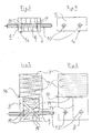
- Figure 1 can be seen a component 1 for thermal insulation between a building-side vertical steel girder 2 and a horizontally projecting outer part 3 in the form of an I-profile beam.
- the device can also be two horizontal or vertical Connecting beams together.
- the component 1 consists of an upper part 1a (see also FIGS. 3 and 4) and a lower part 1b (see also FIGS. 5 and 6).
- the upper part 1a consists of an insulating body 4, which at its the building side facing a plate-like fastening device 5 and at its the Building facing away from a similar plate-like fastening device 6 carries.
- These fastening devices consist in the present case rectangular steel plates that cover the insulating body 4 over the entire surface and flush.
- the lower part 1b consists of an insulating body 4 aligned insulating 7, which on its side facing the building one with the plate 5 in alignment Steel plate 8 and on its side facing away from the building one with the plate. 6 aligned steel plate 9 carries.
- the plates 8 and 9 are in height shorter than the insulating body, so that it protrudes upward and on Insulating body 4 abuts, while the plates 5 and 8 on the one hand and 6 and 9 on the other vertically distanced from each other.
- the upper part 1a is traversed by tension rods 10 in the horizontal direction.
- the Tension rods 10 are fixed with welds 11 to the plates 5 and 6. Instead of the welds could also be done through lock nuts or one waives an attachment and the plates 5 and 6 have only Through holes for subsequent insertion of the tension rods 10 in the Assembly of the outer part 3.
- the lower part 1 b is crossed horizontally by pressure bars 12.
- the printing bars 12 are connected by welded joints 11 with the plates 8 and 9. additionally to the pressure bars 12 are in the lower part 1b stiffeners 13 in the vertical direction and stiffeners 14 integrated in the horizontal direction. Both stiffeners are formed by two intersecting, mirror-image arranged rods. They serve to absorb shear forces.
- one of the insulating body in the embodiment the insulating body 7 of the lower part, in its the plates 8 and 9 projecting area several horizontal parting lines or predetermined separation points (see also Figures 5 and 6).
- the insulating body 7 in its height be trimmed so that upper part 1a and lower part 1b to be connected to the one Components 2 and 3 obtained appropriate height.
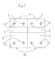
- Figure 2 can be seen the two adjacent tension rods 10; Furthermore the horizontal brace 14 in the lower fastening device in Form of two oblique, intersecting, mirror images in a horizontal plane arranged bars.
- the horizontal stiffener to accommodate horizontal Transverse forces can also be caused by two parallel bars or one Plate are formed.
- the upper part 1a and the lower part 1b each have horizontal through holes for the tension rods 10 and the pressure rods 12. These rods show after Traversing the plates a supernatant for attachment of the invention Component on the one hand on the building, ie on the vertical steel beam 2, on the other for mounting the projecting outer part, so the profile carrier 3.
- This Overhang preferably has a thread, so that the individual parts releasably fastened over nuts.
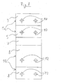
- FIGS. 3 and 4 only the upper part 1a of the component is shown, while FIG Figures 5 and 6 show the lower part 1b of the device.
- FIGS. 5 and 6 again recognizes the predetermined horizontal separation areas 15 in Area between the upper and lower attachment devices. Of course These separation areas could also be added to the upper insulating body 4 be.
- FIG. 8 shows a component in which a plurality of upper parts 1a and a plurality of lower parts 1b are combined. Depending on the static load can be through this modular Construction matching connections also made for special applications become.
- the Isolier Economicsmaschine can with each other and with their both sides plate-like fasteners to be firmly connected, such as by gluing. Usually, however, it is sufficient if they simply between the fastening devices are stuck. Also a subsequent foaming of the gap between the fastening devices may be appropriate, if necessary only after installation on site.
- the device according to the invention for thermal insulation in steel construction characterized by steel beams of different heights and Width can be connected to one and the same standardized component.
Abstract
Description
Die Erfindung betrifft ein Bauelement zur Wärmedämmung zwischen einem Gebäude und einem vorkragenden Außenteil, insbesondere im Stahlbau, bestehend aus einem dazwischen zu verlegenden Isolierkörper mit integrierten Zug-, Druckund gegebenenfalls auch Querkraftelementen, wobei zumindest einige dieser Elemente an der dem Gebäude abgewandten Seite des Isolierkörpers und an der dem Gebäude zugewandten Seite des Isolierkörpers plattenartige Befestigungsvorrichtungen zur Verbindung des Außenteiles mit dem Gebäude tragen.The invention relates to a device for thermal insulation between a building and a projecting outer part, in particular in steel construction, consisting from an insulator to be laid between them with integrated tension, pressure and optionally also transverse force elements, wherein at least some of these elements on the side facing away from the building of the insulating body and on the Building facing side of the insulating plate-like fastening devices to connect the outdoor unit with the building.
Ein solches Bauelement ist aus der DE 199 08 388 bekannt. In Figur 10 dieser Schrift ist dieses Bauelement zum Anschluss eines vorkragenden Stahlbauteils an ein Gebäude, das seinerseits im Stahlbau ausgeführt ist, dargestellt.Such a device is known from DE 199 08 388. In Figure 10 this Scripture is this component for connecting a projecting steel component a building, which in turn is executed in steel construction represented.
Dabei sind beidseits des Isolierkörpers die plattenartigen Befestigungsvorrichtungen in Form von Platten angeordnet, die sich durchgehend über die ganze Höhe des Isolierkörpers erstrecken. Durch die plattenartige Ausbildung der Befestigungsvorrichtung ergeben sich mehrere Vorteile: Erstens wird eine großflächige Anschlussbasis geschaffen, an der die Anschlussteile besonders sicher und gut verankert werden können. Zweitens wird der Isolierkörper im Bereich zwischen den Platten gegen Beschädigung geschützt. Drittens bieten die Platten definierte Anschlusspunkte, an denen sich die Stahlprofile mit ihren genau gearbeiteten und unflexiblen Anschlussflanschen mühelos befestigen lassen. Die Platten sind durch sich kreuzende, in einer Vertikalebene verlaufende Querkraftstäbe miteinander verbunden, so dass eine Einheit aus Isolierkörper und Befestigungsvorrichtungen entsteht. Im oberen Bereich hat diese Einheit eine oder mehrere Durchgangsbohrungen für Zugstäbe, im unteren Bereich entsprechende Bohrungen für Druckstäbe. Both sides of the insulating body, the plate-like fastening devices arranged in the form of plates, extending throughout the whole height extend the insulating body. By the plate-like design of the fastening device There are several advantages: First, a large area Connection base created at the connection parts particularly safe and good can be anchored. Second, the insulator is in the area between the Panels protected against damage. Third, the plates provide defined connection points, where the steel profiles with their precisely worked and easily attach inflexible connection flanges. The plates are through intersecting, transverse in a vertical plane transverse force rods with each other connected, so that a unit of insulating body and fasteners arises. In the upper area, this unit has one or more through holes for tension rods, in the lower area corresponding holes for pressure rods.
Diese Bauelemente haben sich inzwischen in der Praxis gut bewährt. Sie sollen durch die vorliegenden Erfindung hinsichtlich ihrer Einbaumöglichkeiten optimiert werden, insbesondere für den Einsatz im Stahlbau.These components have now proven themselves in practice well. You should optimized by the present invention in terms of their installation options especially for use in steel construction.
Die Erfindung geht dabei von der Erkenntnis aus, dass im Stahlbau - anders als im Betonbau - Anschlussteile mit stark unterschiedlichen geometrischen Abmessungen mit dem wärmedämmenden Bauelement verbunden werden müssen. Daher müssen die erfindungsgemäßen Bauelemente in einer großen Typenvielfalt zur Verfügung stehen, entsprechend den unterschiedlichen Normmaßen der anzuschließenden Bauteile, bei denen es sich meist um 1-Träger handelt.The invention is based on the realization that in steel - unlike in Concrete construction - connecting parts with very different geometrical dimensions must be connected to the heat-insulating component. Therefore the components of the invention in a large variety of types for Available, according to the different standard dimensions of the to be connected Components that are usually 1-carrier.
Dies führt zu einem großen Typen-Aufwand bei der Produktion und Lagerhaltung dieser Bauelemente.This leads to a large type overhead in production and storage of these components.
Diese Problematik wird erfindungsgemäß dadurch gelöst, dass der Isolierkörper mitsamt seinen plattenartigen Befestigungsvorrichtungen in zumindest ein Oberteil und ein Unterteil geteilt ist, dass die plattenartigen Befestigungsvorrichtungen des Oberteils den Zugstäben zugeordnet, die des Unterteils mit den Druckelementen verbunden sind und dass die plattenartigen Befestigungsvorrichtungen von Oberteil und Unterteil vertikal voneinander distanziert sind, wogegen die Isolierkörperteile ohne derartige Distanzierung aufeinander folgen.This problem is inventively achieved in that the insulating body together with its plate-like fastening devices in at least one upper part and a lower part is divided, that the plate-like fastening devices of Upper parts associated with the tension rods, the lower part with the pressure elements are connected and that the plate-like fastening devices of upper part and lower part are vertically spaced apart, whereas the Isolierkörperteile follow each other without such distancing.
Mit diesem Bauelement können aufgrund der höhenmäßig getrennten und dadurch beliebig anpassbaren Befestigungsvorrichtungen beliebig hohe Stahlträger unter thermischer Trennung verbunden werden, ohne dass das Bauelement für jeden Stahlträger speziell angefertigt werden muss. Dadurch vereinfachen sich Produktion und Lagerhaltung ganz erheblich. Außerdem verringern sich die Materialkosten, weil sich die plattenartigen Befestigungsvorrichtungen nicht mehr über die ganze Bauteilhöhe erstrecken. Zusätzlich besteht die Möglichkeit, die unteren und oberen Befestigungsvorrichtungen in unterschiedlicher Wandstärke und horizontaler Abmessung (Breite) auszuführen und sie somit individuell zu optimieren bezüglich ihrer statischen Belastung und ihres Materialaufwands. Schließlich wird die Montage der beidseits anzuschließenden Träger erleichtert, weil Zug- und Druckstäbe getrennt angeschlossen werden. With this device can due to the height separated and thereby arbitrarily adjustable fastening devices arbitrarily high steel beam under Thermal separation can be connected without the device for each Steel beam must be specially made. This simplifies production and storage quite considerably. In addition, the material costs, because the plate-like fasteners no longer over the whole Component height extend. In addition, there is the possibility of the lower and upper Fasteners in different wall thickness and horizontal dimension (Width) and thus to optimize them individually their static load and their material costs. Finally, the assembly facilitated to be connected on both sides carrier because pull and push rods be connected separately.
Bei der Ausgestaltung der Isolierkörper empfiehlt es sich, dass Leerraumvolumina und freie Zwischenräume vermieden werden, da diese aufgrund von Konvektion zu einer schlechteren Wärmedämmung führen. Daher sind die Isolierkörper im Bereich zwischen zwei auf gleicher Höhe liegenden Befestigungsvorrichtungen mehrteilig ausgebildet, so dass sie die integrierten Bewehrungselemente möglichst ohne Zwischenraum umschließen. Die Trennung der Isolierkörper erfolgt vorzugsweise in horizontaler Ebene.In the embodiment of the insulating, it is recommended that void volumes and free spaces are avoided as these due to convection too lead to a poorer thermal insulation. Therefore, the insulator are in the range between two equal fixing devices designed in several parts, so that they the integrated reinforcing elements as possible enclose without gap. The separation of the insulating body is preferably carried out in a horizontal plane.
Zur Höhenanpassung des Isolierkörpers ist es günstig, im Bereich zwischen der oberen und unteren Befestigungsvorrichtung horizontale Trennbereiche in abgestufter Höhe vorzusehen. Dadurch kann der Isolierkörper durch Abschneiden entlang der horizontalen Trennbereiche verkürzt werden, ohne lose Isolierkörperteile zwischen den Platten anzuordnen.To adjust the height of the insulating body, it is favorable in the area between the upper and lower fastening device horizontal separation areas in graduated Provide height. This allows the insulator by cutting along the horizontal separation areas are shortened without loose Isolierkörperteile between the plates.
Damit auch im Zwischenraum zwischen den oberen und unteren plattenartigen Befestigungsvorrichtungen kein Hohlraum entsteht ist es günstig, dass der Isolierkörper in diesen Bereich in Horizontalrichtung vorspringt und mit den Außenseiten der Befestigungsvorrichtung bündig abschließt.Thus also in the space between the upper and lower plate-like Fastening devices no cavity is formed, it is favorable that the insulating body projecting in this area in the horizontal direction and with the outsides the fastening device is flush.
Es ist weiterhin sinnvoll, zumindest in das Unterteil des Bauelements Querkraftstäbe einzubauen. Diese Querkraftstäbe bilden eine Aussteifung in Vertikalrichtung. Dabei ist es im Gegensatz zu den Zug- und Druckstäben nicht notwendig, dass die Querkraftstäbe nach Durchqueren des Isolierkörpers auf den anderen Seiten der plattenförmigen Befestigungsvorrichtungen wieder austreten. Zweckmäßig erfolgt diese Aussteifung in Vertikalrichtung durch zwei schräg verlaufende, sich kreuzende, spiegelbildlich angeordnete Stäbe oder durch ein zwischen den plattenförmigen Befestigungsvorrichtungen eingesetztes einstückiges Blech.It also makes sense, at least in the lower part of the component transverse force rods install. These transverse force bars form a stiffening in the vertical direction. It is in contrast to the tension and compression bars not necessary that the transverse force bars after passing through the insulating body on the other Side of the plate-shaped fastening devices emerge again. expedient this stiffening takes place in the vertical direction by two inclined, intersecting, mirror-image arranged rods or by a between the plate-shaped fastening devices inserted one-piece sheet metal.
Weiterhin ist es zweckmäßig, dass zumindest in der Befestigungsvorrichtung des Unterteils eine Aussteifung in Horizontalrichtung eingebaut ist. Diese Aussteifung in Horizontalrichtung kann beispielsweise ebenfalls durch zwei schräg verlaufende sich kreuzende, spiegelbildlich angeordnete Stäbe erfolgen. Es ist jedoch auch denkbar, dass sie von zwei parallel verlaufenden Stäben oder einer Platte gebildet wird. Die horizontale Aussteifung wird vorzugsweise im oberen Bereich des Unterteils angeordnet.Furthermore, it is expedient that at least in the fastening device of Bottom parts a stiffener is installed in the horizontal direction. This stiffening in the horizontal direction, for example, also by two obliquely intersecting, mirror-image arranged rods done. It is, however conceivable that they are formed by two parallel bars or a plate becomes. The horizontal bracing is preferably in the upper region of the lower part arranged.
Wenn die Aussteifung zwischen gegenüberstehenden Befestigungsvorrichtungen sowohl in Horizontalrichtung wie auch in Vertikalrichtung wirken soll, empfiehlt es sich, ein einstückiges profiliertes Zwischenelement einzusetzen, etwa ein T-Profil oder ein U-Profil. Dadurch können mit einem Element beide Aussteifungsrichtungen abgedeckt werden.If the stiffener between facing fasteners both in the horizontal direction as well as in the vertical direction, it is recommended itself to use a one-piece profiled intermediate element, such as a T-profile or a U-profile. As a result, with one element both stiffening directions be covered.
Eine andere zweckmäßige Alternative besteht darin, die plattenartigen Befestigungselemente in nebeneinander und/oder übereinander angeordnete Elemente zu unterteilen. So kann beispielsweise die Befestigungsvorrichtung des Oberteiles aus zwei benachbarten Elementen bestehen, so dass beispielsweise jedem Zugstab an seinem Ende jeweils eine plattenartige Befestigungsvorrichtung zugeordnet sein kann, die dann bis zur Größe einer Schrauben-Unterlagsscheibe reduziert werden kann.Another expedient alternative is the plate-like fasteners in side by side and / or superimposed elements too divide. For example, the fastening device of the upper part consist of two adjacent elements, so that, for example, each tie rod each associated with a plate-like fastening device at its end can be, which then reduces to the size of a screw washer can be.
Das Oberteil der Befestigungsvorrichtung dient normalerweise zur Aufnahme von Zugkräften, das Unterteil zur Aufnahme von Druckkräften. Je nach statischer Belastung kann jedoch das Oberteil wahlweise auch zur Übertragung von Druckkräften, das Unterteil wahlweise auch zur Übertragung von Zugkräften eingesetzt werden. Die vertikalen und/oder horizontalen Aussteifungen sind je nach Belastungsfall im Unterteil und/oder Oberteil des Bauelementes angeordnet.The upper part of the fastening device is normally used to hold Tensile forces, the lower part for absorbing compressive forces. Depending on the static load However, the upper part optionally also for the transmission of compressive forces, the lower part optionally also be used for the transmission of tensile forces. The vertical and / or horizontal stiffeners are depending on the load case arranged in the lower part and / or upper part of the component.
Weitere erfindungswesentliche Merkmale und Einzelheiten ergeben sich aus der Beschreibung der Zeichnungen; dabei zeigt:
Figur 1- einen Vertikalschnitt durch ein bereits montiertes Bauelement zum Anschluss eines vorkragenden Stahl-Profilträgers an ein Gebäude;
Figur 2- eine Ansicht des eingebauten Bauelementes nach
Figur 1 von oben; Figur 3- eine Seitenansicht eines Oberteils der Befestigungsvorrichtung (quer zu einer gedachten Verbindungsachse vom Gebäude zum Außenteil);
Figur 4- eine Ansicht der Befestigungsvorrichtung nach
Figur 3 in Richtung der gedachten Verbindungsachse vom vorkragenden Außenteil und Gebäude; Figur 5- eine Seitenansicht des Unterteils der Befestigungsvorrichtung zu
Figur 3; Figur 6- eine Ansicht der Befestigungsvorrichtung nach
Figur 5 in Richtung der gedachten Verbindungsachse von vorkragendem Außenteil und Gebäude; Figur 7- eine Ansicht von 2 seitlich nebeneinander angeordneten Bauelementen in Richtung der gedachten Verbindungsachse von vorkragendem Außenteil und Gebäude;
Figur 8- eine Ansicht von mehreren übereinander angeordneten Befestigungsvorrichtungen im Oberteil und mehreren übereinander angeordneten Befestigungsvorrichtungen im Unterteil in Richtung der gedachten Verbindungsachse von auskragendem Außenteil und Gebäude.
- FIG. 1
- a vertical section through an already mounted device for connecting a projecting steel profile carrier to a building;
- FIG. 2
- a view of the built-in component of Figure 1 from above;
- FIG. 3
- a side view of an upper part of the fastening device (transverse to an imaginary connection axis from the building to the outer part);
- FIG. 4
- a view of the fastening device of Figure 3 in the direction of the imaginary connecting axis of the projecting outer part and building;
- FIG. 5
- a side view of the lower part of the fastening device to Figure 3;
- FIG. 6
- a view of the fastening device according to Figure 5 in the direction of the imaginary connection axis of projecting outer part and building;
- FIG. 7
- a view of two side by side arranged components in the direction of the imaginary connection axis of projecting outer part and building;
- FIG. 8
- a view of a plurality of superimposed fastening devices in the upper part and a plurality of superimposed fastening devices in the lower part in the direction of the imaginary connection axis of cantilevered outer part and building.
In Figur 1 erkennt man ein Bauelement 1 zur Wärmedämmung zwischen einem
gebäudeseitigen vertikalen Stahlträger 2 und einem horizontal vorkragenden Außenteil
3 in Form eines I-Profilträger. Anstelle einer Verbindung des Gebäudes mit
einem horizontalen Träger, kann das Bauelement auch zwei horizontale oder vertikale
Träger miteinander verbinden. Das Bauelement 1 besteht aus einem Oberteil
1a (siehe auch Figur 3 und 4) und einem Unterteil 1b (siehe auch Figur 5 und 6).In Figure 1 can be seen a
Das Oberteil 1a besteht aus einem Isolierkörper 4, der an seiner dem Gebäude
zugewandten Seite eine plattenartige Befestigungsvorrichtung 5 und an seiner dem
Gebäude abgewandten Seite eine gleichartige plattenartige Befestigungsvorrichtung
6 trägt. Diese Befestigungsvorrichtungen bestehen im vorliegenden Fall aus
rechteckigen Stahlplatten, die den Isolierkörper 4 vollflächig und bündig abdecken.The
Das Unterteil 1b besteht aus einem zum Isolierkörper 4 fluchtenden Isolierkörper
7, der an seiner dem Gebäude zugewandten Seite eine mit der Platte 5 fluchtende
Stahlplatte 8 und an seiner dem Gebäude abgewandten Seite eine mit der Platte 6
fluchtende Stahlplatte 9 trägt. Dabei sind die Platten 8 und 9 in ihrer Höhe jedoch
kürzer bemessen als der Isolierkörper, so dass dieser nach oben vorsteht und am
Isolierkörper 4 anstößt, während die Platten 5 und 8 einerseits und 6 und 9 andererseits
vertikal voneinander distanziert sind.The lower part 1b consists of an insulating
Im Bereich des vertikalen Zwischenraums zwischen den Platten springt der Isolierkörper
7 in Horizontalrichtung vor und schließt mit den Außenseiten der Befestigungsvorrichtungen
bündig ab.In the area of the vertical space between the plates jumps the insulating
Das Oberteil 1a wird von Zugstäben 10 in horizontaler Richtung durchquert. Die
Zugstäbe 10 sind mit Schweißnähten 11 an den Platten 5 und 6 festgelegt. Anstelle
der Schweißnähte könnte die Festlegung auch durch Kontermuttern erfolgen
oder man verzichtet auf eine Befestigung und die Platten 5 und 6 haben nur
Durchgangsbohrungen zum nachträglichen Durchstecken der Zugstäbe 10 bei der
Montage des Außenteils 3.The
Das Unterteil 1b wird von Druckstäben 12 horizontal durchquert. Die Druckstäbe
12 sind durch Schweißverbindungen 11 mit den Platten 8 und 9 verbunden. Zusätzlich
zu den Druckstäben 12 sind im Unterteil 1b Aussteifungen 13 in Vertikalrichtung
und Aussteifungen 14 in Horizontalrichtung integriert. Beide Aussteifungen
werden von zwei sich kreuzenden, spiegelbildlich angeordneten Stäben gebildet.
Sie dienen zur Aufnahme von Querkräften.The lower part 1 b is crossed horizontally by pressure bars 12. The printing bars
12 are connected by welded
Außerdem erkennt man in der Zeichnung, dass einer der Isolierkörper, im Ausführungsbeispiel
der Isolierkörper 7 des unteren Teils, in seinem die Platten 8 und 9
überragenden Bereich mehrere horizontale Trennebenen bzw. Solltrennstellen
(vgl. auch Figur 5 und 6) aufweist. Dadurch kann der Isolierkörper 7 in seiner Höhe
so gestutzt werden, dass Oberteil 1a und Unterteil 1b eine zu den anzuschließenden
Bauteilen 2 und 3 passende Höhe erhalten. Es liegt statt dessen auch im
Rahmen der Erfindung, die vertikale Distanzierung der Platten 5, 6 gegenüber den
Platten 8, 9 dadurch einzustellen, dass man zwischen die Isolierkörper 4 und 7
zusätzliche Zwischenlagen aus Isoliermaterial einschiebt.In addition, it can be seen in the drawing that one of the insulating body, in the embodiment
the insulating
In Figur 2 erkennt man die beiden nebeneinander angeordneten Zugstäbe 10; außerdem
die horizontale Aussteifung 14 in der unteren Befestigungsvorrichtung in
Form von zwei schräg verlaufenden, sich kreuzenden, spiegelbildlich in einer Horizontalebene
angeordneten Stäbe. Die horizontale Aussteifung zur Aufnahme horizontaler
Querkräfte kann auch durch zwei parallel verlaufende Stäbe oder eine
Platte gebildet werden.In Figure 2 can be seen the two
Das Oberteil 1a und das Unterteil 1b haben jeweils horizontale Durchgangsbohrungen
für die Zugstäbe 10 und die Druckstäbe 12. Diese Stäbe weisen nach
Durchquerung der Platten einen Überstand zur Befestigung des erfindungsgemäßen
Bauteils einerseits am Gebäude, also am vertikalen Stahlträger 2, andererseits
zur Montage des vorkragenden Außenteils, also des Profilträgers 3 auf. Dieser
Überstand hat vorzugsweise ein Gewinde, so dass sich die einzelnen Teile
lösbar über Muttern befestigen lassen.The
In den Figuren 3 und 4 ist nur das Oberteil 1a des Bauelements dargestellt, während
die Figuren 5 und 6 das Unterteil 1b des Bauelements zeigen. In den Figuren
5 und 6 erkennt man wieder die vorgegebenen horizontalen Trennbereiche 15 im
Bereich zwischen den oberen und unteren Befestigungsvorrichtungen. Selbstverständlich
könnten diese Trennbereiche auch dem oberen Isolierkörper 4 zugeschlagen
sein.In FIGS. 3 and 4, only the
In Figur 7 sind zwei Bauteile seitlich nebeneinander angeordnet. Dadurch wird ermöglicht, dass mit einem Standardbauelement Stahlbauverbindungen auch für in der Breite variierende Stahlträger hergestellt werden können.In Figure 7, two components are arranged side by side. This will allow that with a standard structural steel connections also for in the width varying steel beams can be made.
Figur 8 zeigt ein Bauelement, bei dem mehrere Oberteile 1a und mehrere Unterteile
1b kombiniert sind. Je nach statischer Belastung können durch diese modulare
Bauweise passende Verbindungen auch für Spezialanwendungen hergestellt
werden.FIG. 8 shows a component in which a plurality of
Die Isolierkörperteile können untereinander und mit ihren beidseits anliegenden plattenartigen Befestigungsvorrichtungen fest verbunden sein, etwa durch Kleben. Meist genügt es aber, wenn sie einfach zwischen den Befestigungsvorrichtungen verklemmt sind. Auch ein nachträgliches Ausschäumen des Zwischenraumes zwischen den Befestigungsvorrichtungen kann zweckmäßig sein, gegebenenfalls erst nach der Montage vor Ort. The Isolierkörperteile can with each other and with their both sides plate-like fasteners to be firmly connected, such as by gluing. Usually, however, it is sufficient if they simply between the fastening devices are stuck. Also a subsequent foaming of the gap between the fastening devices may be appropriate, if necessary only after installation on site.
Zusammenfassend zeichnet sich das erfindungsgemäße Bauelement zur Wärmedämmung im Stahlbau dadurch aus, dass Stahlträger unterschiedlicher Höhe und Breite mit ein und demselben standardisierten Bauelement verbunden werden können.In summary, the device according to the invention for thermal insulation in steel construction characterized by steel beams of different heights and Width can be connected to one and the same standardized component.
Claims (14)
dadurch gekennzeichnet, dass der Isolierkörper mitsamt seinen plattenartigen Befestigungsvorrichtungen in zumindest ein Oberteil (1a) und ein Unterteil (1b) geteilt ist, dass die plattenartigen Befestigungsvorrichtungen (5, 6) des Oberteils (1a) den Zugelementen (10) zugeordnet, die Befestigungsvorrichtungen (8, 9) des Unterteils (1b) mit den Druckelementen (12) verbunden sind und dass die plattenartigen Befestigungsvorrichtungen (5, 6; 8, 9) von Oberteil und Unterteil vertikal voneinander distanziert sind, wogegen die Isolierkörperteile (4, 7) ohne derartige Distanzierung aufeinander folgen.Component for thermal insulation (1) between a building (2) and a cantilevered outer part (3), in particular in steel construction, consisting of an insulator to be laid therebetween with tensile, compressive and optionally transverse force elements guided therein, at least some of these elements being attached to the the side facing away from the building of the insulating body and on the side facing the building of the insulating wear plate-like fastening devices for connecting the outer part with the building,
characterized in that the insulating body together with its plate-like fastening devices is divided into at least one upper part (1a) and one lower part (1b), that the plate-like fastening devices (5, 6) of the upper part (1a) associated with the tension elements (10), the fastening devices ( 8, 9) of the lower part (1b) are connected to the pressure elements (12) and that the plate-like fastening devices (5, 6; 8, 9) are vertically spaced from the upper part and the lower part, whereas the Isolierkörperteile (4, 7) without such Distancing follow each other.
dadurch gekennzeichnet, dass die Isolierkörperteile (4, 7) im Bereich zwischen zwei auf gleicher Höhe liegenden Befestigungsvorrichtungen (5, 6; 8, 9) mehrteilig ausgebildet sind.Component according to Claim 1,
characterized in that the Isolierkörperteile (4, 7) in the region between two at the same level fastening devices (5, 6, 8, 9) are formed in several parts.
dadurch gekennzeichnet, dass der Isolierkörperteil (7) im Bereich zwischen den oberen und unteren Befestigungsvorrichtungen mehrere vorgegebene horizontale Trennbereiche (15) in abgestufter Höhe aufweist. Component according to Claim 1,
characterized in that the Isolierkörperteil (7) in the region between the upper and lower fastening devices a plurality of predetermined horizontal separation areas (15) in a stepped height.
dadurch gekennzeichnet, dass der Isolierkörperteil (7) im Zwischenraum zwischen den oberen und unteren plattenartigen Befestigungsvorrichtungen und gegebenenfalls seitlich neben den Befestigungsvorrichtungen in Horizontalrichtung vorspringt und mit den Außenseiten der Befestigungsvorrichtungen bündig abschließt.Component according to Claim 1,
characterized in that the Isolierkörperteil (7) in the space between the upper and lower plate-like fastening devices and optionally laterally next to the fastening devices in the horizontal direction protrudes and flush with the outer sides of the fastening devices.
dadurch gekennzeichnet, dass zwischen den Befestigungsvorrichtungen des Oberteils (5, 6) und/oder des Unterteils (8, 9) eine Aussteifung in Vertikalrichtung (13) eingebaut ist.Component according to Claim 1,
characterized in that a stiffening in the vertical direction (13) is installed between the fastening devices of the upper part (5, 6) and / or the lower part (8, 9).
dadurch gekennzeichnet, dass die Aussteifung in Vertikalrichtung (13) durch zwei schräg verlaufende, sich kreuzende, spiegelbildlich angeordnete Stäbe oder durch eine Platte erfolgt.Component at least according to claim 5,
characterized in that the stiffening in the vertical direction (13) by two oblique, intersecting, mirror image arranged rods or by a plate.
dadurch gekennzeichnet, dass zwischen den Befestigungsvorrichtungen des Oberteils (1a) und/oder des Unterteils (1b) eine Aussteifung in Horizontalrichtung (14) eingebaut ist.Component according to Claim 1,
characterized in that a stiffening in the horizontal direction (14) is installed between the fastening devices of the upper part (1a) and / or the lower part (1b).
dadurch gekennzeichnet, dass die Aussteifung in Horizontalrichtung (14) durch zwei schräg verlaufende sich kreuzende, spiegelbildlich angeordnete Stäbe oder durch zumindest zwei parallel verlaufende Stäbe oder eine Platte erfolgt.Component according to at least claim 7,
characterized in that the stiffening in the horizontal direction (14) by two obliquely intersecting, mirror image arranged rods or by at least two parallel rods or a plate takes place.
dadurch gekennzeichnet, dass die vertikale und/oder horizontale Aussteifung im Unterteil (1b) des Bauelementes angeordnet ist. Component at least according to claims 5 and 7,
characterized in that the vertical and / or horizontal stiffening in the lower part (1b) of the component is arranged.
dadurch gekennzeichnet, dass die horizontale Aussteifung (14) im oberen Bereich des Unterteils (1b) angeordnet ist.Component at least according to claim 9,
characterized in that the horizontal stiffener (14) in the upper region of the lower part (1b) is arranged.
dadurch gekennzeichnet, dass die vertikale und horizontale Aussteifung durch ein einstückiges Profil, insbesondere ein T-Profil gebildet wird.Component according to Claims 5 and 7,
characterized in that the vertical and horizontal stiffening is formed by a one-piece profile, in particular a T-profile.
dadurch gekennzeichnet, dass die plattenartigen Befestigungselemente (5, 6, 8, 9) von Oberteil und Unterteil unterschiedlich dimensioniert sind.Component according to Claim 1,
characterized in that the plate-like fastening elements (5, 6, 8, 9) of upper part and lower part are dimensioned differently.
dadurch gekennzeichnet, dass die plattenartigen Befestigungselemente in nebeneinander und/oder übereinander angeordnete Elemente unterteilt sind.Component according to claim 1
characterized in that the plate-like fastening elements are divided into side by side and / or superimposed elements.
dadurch gekennzeichnet, dass das Oberteil (1a) wahlweise auch zur Übertragung von Druckkräften, das Unterteil (1b) wahlweise auch zur Übertragung von Zugkräften einsetzbar ist.Component according to at least one of the preceding claims,
characterized in that the upper part (1a) optionally also for the transmission of compressive forces, the lower part (1b) optionally also for the transmission of tensile forces can be used.
Applications Claiming Priority (2)
| Application Number | Priority Date | Filing Date | Title |
|---|---|---|---|
| DE10130866A DE10130866A1 (en) | 2001-06-22 | 2001-06-22 | Component for thermal insulation |
| DE10130866 | 2001-06-22 |
Publications (3)
| Publication Number | Publication Date |
|---|---|
| EP1270833A2 true EP1270833A2 (en) | 2003-01-02 |
| EP1270833A3 EP1270833A3 (en) | 2003-12-03 |
| EP1270833B1 EP1270833B1 (en) | 2005-12-28 |
Family
ID=7689554
Family Applications (1)
| Application Number | Title | Priority Date | Filing Date |
|---|---|---|---|
| EP02008611A Expired - Lifetime EP1270833B1 (en) | 2001-06-22 | 2002-04-17 | Heat-insulating construction element |
Country Status (4)
| Country | Link |
|---|---|
| EP (1) | EP1270833B1 (en) |
| AT (1) | ATE314535T1 (en) |
| DE (2) | DE10130866A1 (en) |
| PL (1) | PL206390B1 (en) |
Cited By (3)
| Publication number | Priority date | Publication date | Assignee | Title |
|---|---|---|---|---|
| EP2072700A2 (en) * | 2007-12-18 | 2009-06-24 | fischerwerke GmbH & Co. KG | Fastening element |
| AT513322A1 (en) * | 2012-09-06 | 2014-03-15 | Hans Hoellwart Forschungszentrum Fuer Integrales Bauwesen Ag | Thermally insulating support element |
| GB2583314B (en) * | 2020-07-23 | 2022-11-02 | Laing Orourke Plc | Façade construction using through wall thermal stud |
Families Citing this family (5)
| Publication number | Priority date | Publication date | Assignee | Title |
|---|---|---|---|---|
| DE102006011335A1 (en) * | 2006-03-09 | 2007-09-13 | Schöck Bauteile GmbH | Thermal insulation component for use between e.g. ceiling and balcony, has insulating body with foot and reinforcement parts, where reinforcement part is arranged vertically over foot part, and has horizontal length smaller than foot part |
| DE102011056967A1 (en) * | 2011-12-23 | 2013-06-27 | Max Frank Gmbh & Co. Kg | Plate connecting element |
| DE102014113662A1 (en) | 2014-09-22 | 2016-03-24 | Max Frank Gmbh & Co. Kg | connecting element |
| DE102019118363B4 (en) | 2019-07-08 | 2021-07-15 | Max Frank Gmbh & Co. Kg | Arrangement for connecting a structural part with an external steel part in front of the structural part |
| DE102019133997A1 (en) | 2019-12-11 | 2021-06-17 | Max Frank Gmbh & Co. Kg | Arrangement for connecting a structural part to an outer part located in front of the structural part |
Citations (1)
| Publication number | Priority date | Publication date | Assignee | Title |
|---|---|---|---|---|
| DE19908388A1 (en) | 1999-02-26 | 2000-08-31 | Schoeck Bauteile Gmbh | Building insulating element between building and clad steel uses connecting element adjustably fixed and angled relative insulating element to sides or in height. |
Family Cites Families (2)
| Publication number | Priority date | Publication date | Assignee | Title |
|---|---|---|---|---|
| DE3403537A1 (en) * | 1984-02-02 | 1985-08-08 | Veit Dennert KG Baustoffbetriebe, 8602 Schlüsselfeld | Prefabricated balcony-construction element for buildings |
| CH690966A5 (en) * | 1996-03-12 | 2001-03-15 | Clement Gutzwiller | Connecting component for collar plates on buildings comprises thermic insulating body and at least one metal reinforcement component arranged crossways to insulating body |
-
2001
- 2001-06-22 DE DE10130866A patent/DE10130866A1/en not_active Withdrawn
-
2002
- 2002-04-17 DE DE50205404T patent/DE50205404D1/en not_active Expired - Lifetime
- 2002-04-17 EP EP02008611A patent/EP1270833B1/en not_active Expired - Lifetime
- 2002-04-17 AT AT02008611T patent/ATE314535T1/en active
- 2002-06-11 PL PL354429A patent/PL206390B1/en unknown
Patent Citations (1)
| Publication number | Priority date | Publication date | Assignee | Title |
|---|---|---|---|---|
| DE19908388A1 (en) | 1999-02-26 | 2000-08-31 | Schoeck Bauteile Gmbh | Building insulating element between building and clad steel uses connecting element adjustably fixed and angled relative insulating element to sides or in height. |
Cited By (5)
| Publication number | Priority date | Publication date | Assignee | Title |
|---|---|---|---|---|
| EP2072700A2 (en) * | 2007-12-18 | 2009-06-24 | fischerwerke GmbH & Co. KG | Fastening element |
| EP2072700A3 (en) * | 2007-12-18 | 2014-04-16 | fischerwerke GmbH & Co. KG | Fastening element |
| AT513322A1 (en) * | 2012-09-06 | 2014-03-15 | Hans Hoellwart Forschungszentrum Fuer Integrales Bauwesen Ag | Thermally insulating support element |
| AT513322B1 (en) * | 2012-09-06 | 2014-10-15 | Hans Höllwart Forschungszentrum Für Integrales Bauwesen Ag | Thermally insulating support element |
| GB2583314B (en) * | 2020-07-23 | 2022-11-02 | Laing Orourke Plc | Façade construction using through wall thermal stud |
Also Published As
| Publication number | Publication date |
|---|---|
| PL206390B1 (en) | 2010-08-31 |
| ATE314535T1 (en) | 2006-01-15 |
| DE10130866A1 (en) | 2003-01-02 |
| DE50205404D1 (en) | 2006-02-02 |
| PL354429A1 (en) | 2002-12-30 |
| EP1270833A3 (en) | 2003-12-03 |
| EP1270833B1 (en) | 2005-12-28 |
Similar Documents
| Publication | Publication Date | Title |
|---|---|---|
| DE1903129B2 (en) | Device for connecting a beam to a concrete column | |
| DE1684795B2 (en) | Box with concrete walls, which are bordered by metal profile beams | |
| DE1810434C3 (en) | Building structure | |
| DE3128165A1 (en) | SOUND-INSULATING WALL CONSTRUCTION SYSTEM FOR INDUSTRIAL BUILDINGS AND CASSETTE PROFILE HERE | |
| EP1270833B1 (en) | Heat-insulating construction element | |
| DE102019125318A1 (en) | Playing field delimitation for a small playing field | |
| EP2281959B1 (en) | Connector element for cantilever slab | |
| EP1630315A1 (en) | Construction element for shear and punching reinforcement | |
| CH711841B1 (en) | Insulating connection element for concrete components. | |
| EP1031668B1 (en) | Building element for heat insulation | |
| DE102019133999A1 (en) | Arrangement for connecting a structural part to an outer part located in front of the structural part | |
| DE2537244A1 (en) | FENCE | |
| EP0133875B1 (en) | Insulated construction element for buildings | |
| CH651095A5 (en) | REINFORCEMENT ELEMENT FOR TRANSMITTING LATERAL FORCES IN PANEL-LIKE SUPPORT LINKS, e.g. FLAT CEILINGS. | |
| EP1860246B1 (en) | Building element for heat insulation | |
| EP2337903B1 (en) | Connection elements for building connections | |
| DE8336223U1 (en) | SOUND INSULATING WALL | |
| EP2607560B1 (en) | Slab connection element | |
| DE2336482A1 (en) | Prefabricated steel-skeleton room cell units - with frames of hollow sections covered by inner and outer insulating panels | |
| DE102008002899A1 (en) | Component for connecting external building part e.g. wall, and building, has stainless steel support for force-fit connection of external building part, where support is designed as double-T-stainless steel support | |
| DE202016105596U1 (en) | Structure and buildings | |
| DE102016118014A1 (en) | Trusses, in particular roof trusses for a hall | |
| DE1784253A1 (en) | Wall element, especially for log houses | |
| DE2750931C2 (en) | ||
| DE2902231C2 (en) | Roof or surface component that consists of at least one trapezoidal profile sheet and forms a shear field |
Legal Events
| Date | Code | Title | Description |
|---|---|---|---|
| PUAI | Public reference made under article 153(3) epc to a published international application that has entered the european phase |
Free format text: ORIGINAL CODE: 0009012 |
|
| AK | Designated contracting states |
Kind code of ref document: A2 Designated state(s): AT BE CH CY DE DK ES FI FR GB GR IE IT LI LU MC NL PT SE TR |
|
| AX | Request for extension of the european patent |
Free format text: AL;LT;LV;MK;RO;SI |
|
| PUAL | Search report despatched |
Free format text: ORIGINAL CODE: 0009013 |
|
| AK | Designated contracting states |
Kind code of ref document: A3 Designated state(s): AT BE CH CY DE DK ES FI FR GB GR IE IT LI LU MC NL PT SE TR |
|
| AX | Request for extension of the european patent |
Extension state: AL LT LV MK RO SI |
|
| 17P | Request for examination filed |
Effective date: 20040206 |
|
| AKX | Designation fees paid |
Designated state(s): AT BE CH CY DE DK ES FI FR GB GR IE IT LI LU MC NL PT SE TR |
|
| RAP1 | Party data changed (applicant data changed or rights of an application transferred) |
Owner name: SCHOECK BAUTEILE GMBH |
|
| GRAP | Despatch of communication of intention to grant a patent |
Free format text: ORIGINAL CODE: EPIDOSNIGR1 |
|
| GRAP | Despatch of communication of intention to grant a patent |
Free format text: ORIGINAL CODE: EPIDOSNIGR1 |
|
| GRAS | Grant fee paid |
Free format text: ORIGINAL CODE: EPIDOSNIGR3 |
|
| GRAA | (expected) grant |
Free format text: ORIGINAL CODE: 0009210 |
|
| AK | Designated contracting states |
Kind code of ref document: B1 Designated state(s): AT BE CH CY DE DK ES FI FR GB GR IE IT LI LU MC NL PT SE TR |
|
| PG25 | Lapsed in a contracting state [announced via postgrant information from national office to epo] |
Ref country code: FI Free format text: LAPSE BECAUSE OF FAILURE TO SUBMIT A TRANSLATION OF THE DESCRIPTION OR TO PAY THE FEE WITHIN THE PRESCRIBED TIME-LIMIT Effective date: 20051228 Ref country code: IT Free format text: LAPSE BECAUSE OF FAILURE TO SUBMIT A TRANSLATION OF THE DESCRIPTION OR TO PAY THE FEE WITHIN THE PRESCRIBED TIME-LIMIT;WARNING: LAPSES OF ITALIAN PATENTS WITH EFFECTIVE DATE BEFORE 2007 MAY HAVE OCCURRED AT ANY TIME BEFORE 2007. THE CORRECT EFFECTIVE DATE MAY BE DIFFERENT FROM THE ONE RECORDED. Effective date: 20051228 |
|
| REG | Reference to a national code |
Ref country code: GB Ref legal event code: FG4D Free format text: NOT ENGLISH |
|
| REG | Reference to a national code |
Ref country code: CH Ref legal event code: EP |
|
| REG | Reference to a national code |
Ref country code: IE Ref legal event code: FG4D Free format text: LANGUAGE OF EP DOCUMENT: GERMAN |
|
| REF | Corresponds to: |
Ref document number: 50205404 Country of ref document: DE Date of ref document: 20060202 Kind code of ref document: P |
|
| REG | Reference to a national code |
Ref country code: CH Ref legal event code: NV Representative=s name: R. A. EGLI & CO. PATENTANWAELTE |
|
| PG25 | Lapsed in a contracting state [announced via postgrant information from national office to epo] |
Ref country code: SE Free format text: LAPSE BECAUSE OF FAILURE TO SUBMIT A TRANSLATION OF THE DESCRIPTION OR TO PAY THE FEE WITHIN THE PRESCRIBED TIME-LIMIT Effective date: 20060328 Ref country code: GR Free format text: LAPSE BECAUSE OF FAILURE TO SUBMIT A TRANSLATION OF THE DESCRIPTION OR TO PAY THE FEE WITHIN THE PRESCRIBED TIME-LIMIT Effective date: 20060328 Ref country code: DK Free format text: LAPSE BECAUSE OF FAILURE TO SUBMIT A TRANSLATION OF THE DESCRIPTION OR TO PAY THE FEE WITHIN THE PRESCRIBED TIME-LIMIT Effective date: 20060328 |
|
| PG25 | Lapsed in a contracting state [announced via postgrant information from national office to epo] |
Ref country code: ES Free format text: LAPSE BECAUSE OF FAILURE TO SUBMIT A TRANSLATION OF THE DESCRIPTION OR TO PAY THE FEE WITHIN THE PRESCRIBED TIME-LIMIT Effective date: 20060408 |
|
| GBT | Gb: translation of ep patent filed (gb section 77(6)(a)/1977) |
Effective date: 20060329 |
|
| PG25 | Lapsed in a contracting state [announced via postgrant information from national office to epo] |
Ref country code: MC Free format text: LAPSE BECAUSE OF NON-PAYMENT OF DUE FEES Effective date: 20060430 Ref country code: BE Free format text: LAPSE BECAUSE OF NON-PAYMENT OF DUE FEES Effective date: 20060430 |
|
| PG25 | Lapsed in a contracting state [announced via postgrant information from national office to epo] |
Ref country code: PT Free format text: LAPSE BECAUSE OF FAILURE TO SUBMIT A TRANSLATION OF THE DESCRIPTION OR TO PAY THE FEE WITHIN THE PRESCRIBED TIME-LIMIT Effective date: 20060529 |
|
| ET | Fr: translation filed | ||
| PLBE | No opposition filed within time limit |
Free format text: ORIGINAL CODE: 0009261 |
|
| STAA | Information on the status of an ep patent application or granted ep patent |
Free format text: STATUS: NO OPPOSITION FILED WITHIN TIME LIMIT |
|
| 26N | No opposition filed |
Effective date: 20060929 |
|
| BERE | Be: lapsed |
Owner name: SCHOCK BAUTEILE G.M.B.H. Effective date: 20060430 |
|
| PG25 | Lapsed in a contracting state [announced via postgrant information from national office to epo] |
Ref country code: LU Free format text: LAPSE BECAUSE OF NON-PAYMENT OF DUE FEES Effective date: 20060417 Ref country code: TR Free format text: LAPSE BECAUSE OF FAILURE TO SUBMIT A TRANSLATION OF THE DESCRIPTION OR TO PAY THE FEE WITHIN THE PRESCRIBED TIME-LIMIT Effective date: 20051228 |
|
| PG25 | Lapsed in a contracting state [announced via postgrant information from national office to epo] |
Ref country code: CY Free format text: LAPSE BECAUSE OF FAILURE TO SUBMIT A TRANSLATION OF THE DESCRIPTION OR TO PAY THE FEE WITHIN THE PRESCRIBED TIME-LIMIT Effective date: 20051228 |
|
| REG | Reference to a national code |
Ref country code: FR Ref legal event code: PLFP Year of fee payment: 15 |
|
| REG | Reference to a national code |
Ref country code: FR Ref legal event code: PLFP Year of fee payment: 16 |
|
| REG | Reference to a national code |
Ref country code: FR Ref legal event code: PLFP Year of fee payment: 17 |
|
| PGFP | Annual fee paid to national office [announced via postgrant information from national office to epo] |
Ref country code: IE Payment date: 20180418 Year of fee payment: 17 |
|
| PGFP | Annual fee paid to national office [announced via postgrant information from national office to epo] |
Ref country code: FR Payment date: 20190423 Year of fee payment: 18 |
|
| PG25 | Lapsed in a contracting state [announced via postgrant information from national office to epo] |
Ref country code: IE Free format text: LAPSE BECAUSE OF NON-PAYMENT OF DUE FEES Effective date: 20190417 |
|
| PG25 | Lapsed in a contracting state [announced via postgrant information from national office to epo] |
Ref country code: FR Free format text: LAPSE BECAUSE OF NON-PAYMENT OF DUE FEES Effective date: 20200430 |
|
| PGFP | Annual fee paid to national office [announced via postgrant information from national office to epo] |
Ref country code: DE Payment date: 20210423 Year of fee payment: 20 |
|
| PGFP | Annual fee paid to national office [announced via postgrant information from national office to epo] |
Ref country code: AT Payment date: 20210420 Year of fee payment: 20 Ref country code: GB Payment date: 20210422 Year of fee payment: 20 Ref country code: CH Payment date: 20210422 Year of fee payment: 20 |
|
| PGFP | Annual fee paid to national office [announced via postgrant information from national office to epo] |
Ref country code: NL Payment date: 20210421 Year of fee payment: 20 |
|
| REG | Reference to a national code |
Ref country code: DE Ref legal event code: R071 Ref document number: 50205404 Country of ref document: DE |
|
| REG | Reference to a national code |
Ref country code: NL Ref legal event code: MK Effective date: 20220416 |
|
| REG | Reference to a national code |
Ref country code: CH Ref legal event code: PL |
|
| REG | Reference to a national code |
Ref country code: GB Ref legal event code: PE20 Expiry date: 20220416 |
|
| REG | Reference to a national code |
Ref country code: AT Ref legal event code: MK07 Ref document number: 314535 Country of ref document: AT Kind code of ref document: T Effective date: 20220417 |
|
| PG25 | Lapsed in a contracting state [announced via postgrant information from national office to epo] |
Ref country code: GB Free format text: LAPSE BECAUSE OF EXPIRATION OF PROTECTION Effective date: 20220416 |